WO2013187038A1 - 廃水処理装置、廃水処理システム、排気再循環ユニット、エンジンシステム、及び船舶 - Google Patents
廃水処理装置、廃水処理システム、排気再循環ユニット、エンジンシステム、及び船舶 Download PDFInfo
- Publication number
- WO2013187038A1 WO2013187038A1 PCT/JP2013/003628 JP2013003628W WO2013187038A1 WO 2013187038 A1 WO2013187038 A1 WO 2013187038A1 JP 2013003628 W JP2013003628 W JP 2013003628W WO 2013187038 A1 WO2013187038 A1 WO 2013187038A1
- Authority
- WO
- WIPO (PCT)
- Prior art keywords
- scrubber
- wastewater
- dust
- exhaust gas
- waste water
- Prior art date
Links
Images


Classifications
-
- B—PERFORMING OPERATIONS; TRANSPORTING
- B01—PHYSICAL OR CHEMICAL PROCESSES OR APPARATUS IN GENERAL
- B01D—SEPARATION
- B01D21/00—Separation of suspended solid particles from liquids by sedimentation
- B01D21/0039—Settling tanks provided with contact surfaces, e.g. baffles, particles
- B01D21/0048—Plurality of plates inclined in alternating directions
-
- B—PERFORMING OPERATIONS; TRANSPORTING
- B01—PHYSICAL OR CHEMICAL PROCESSES OR APPARATUS IN GENERAL
- B01D—SEPARATION
- B01D21/00—Separation of suspended solid particles from liquids by sedimentation
- B01D21/0039—Settling tanks provided with contact surfaces, e.g. baffles, particles
- B01D21/0045—Plurality of essentially parallel plates
-
- B—PERFORMING OPERATIONS; TRANSPORTING
- B01—PHYSICAL OR CHEMICAL PROCESSES OR APPARATUS IN GENERAL
- B01D—SEPARATION
- B01D21/00—Separation of suspended solid particles from liquids by sedimentation
- B01D21/0039—Settling tanks provided with contact surfaces, e.g. baffles, particles
- B01D21/0051—Plurality of tube like channels
-
- B—PERFORMING OPERATIONS; TRANSPORTING
- B01—PHYSICAL OR CHEMICAL PROCESSES OR APPARATUS IN GENERAL
- B01D—SEPARATION
- B01D21/00—Separation of suspended solid particles from liquids by sedimentation
- B01D21/26—Separation of sediment aided by centrifugal force or centripetal force
- B01D21/262—Separation of sediment aided by centrifugal force or centripetal force by using a centrifuge
-
- B—PERFORMING OPERATIONS; TRANSPORTING
- B01—PHYSICAL OR CHEMICAL PROCESSES OR APPARATUS IN GENERAL
- B01D—SEPARATION
- B01D21/00—Separation of suspended solid particles from liquids by sedimentation
- B01D21/28—Mechanical auxiliary equipment for acceleration of sedimentation, e.g. by vibrators or the like
- B01D21/283—Settling tanks provided with vibrators
-
- B—PERFORMING OPERATIONS; TRANSPORTING
- B01—PHYSICAL OR CHEMICAL PROCESSES OR APPARATUS IN GENERAL
- B01D—SEPARATION
- B01D47/00—Separating dispersed particles from gases, air or vapours by liquid as separating agent
- B01D47/02—Separating dispersed particles from gases, air or vapours by liquid as separating agent by passing the gas or air or vapour over or through a liquid bath
-
- B—PERFORMING OPERATIONS; TRANSPORTING
- B01—PHYSICAL OR CHEMICAL PROCESSES OR APPARATUS IN GENERAL
- B01D—SEPARATION
- B01D47/00—Separating dispersed particles from gases, air or vapours by liquid as separating agent
- B01D47/06—Spray cleaning
-
- B—PERFORMING OPERATIONS; TRANSPORTING
- B63—SHIPS OR OTHER WATERBORNE VESSELS; RELATED EQUIPMENT
- B63B—SHIPS OR OTHER WATERBORNE VESSELS; EQUIPMENT FOR SHIPPING
- B63B25/00—Load-accommodating arrangements, e.g. stowing, trimming; Vessels characterised thereby
- B63B25/02—Load-accommodating arrangements, e.g. stowing, trimming; Vessels characterised thereby for bulk goods
- B63B25/08—Load-accommodating arrangements, e.g. stowing, trimming; Vessels characterised thereby for bulk goods fluid
-
- B—PERFORMING OPERATIONS; TRANSPORTING
- B63—SHIPS OR OTHER WATERBORNE VESSELS; RELATED EQUIPMENT
- B63H—MARINE PROPULSION OR STEERING
- B63H21/00—Use of propulsion power plant or units on vessels
- B63H21/32—Arrangements of propulsion power-unit exhaust uptakes; Funnels peculiar to vessels
-
- B—PERFORMING OPERATIONS; TRANSPORTING
- B63—SHIPS OR OTHER WATERBORNE VESSELS; RELATED EQUIPMENT
- B63J—AUXILIARIES ON VESSELS
- B63J2/00—Arrangements of ventilation, heating, cooling, or air-conditioning
- B63J2/02—Ventilation; Air-conditioning
- B63J2/08—Ventilation; Air-conditioning of holds
-
- B—PERFORMING OPERATIONS; TRANSPORTING
- B63—SHIPS OR OTHER WATERBORNE VESSELS; RELATED EQUIPMENT
- B63J—AUXILIARIES ON VESSELS
- B63J4/00—Arrangements of installations for treating ballast water, waste water, sewage, sludge, or refuse, or for preventing environmental pollution not otherwise provided for
- B63J4/004—Arrangements of installations for treating ballast water, waste water, sewage, sludge, or refuse, or for preventing environmental pollution not otherwise provided for for treating sludge, e.g. tank washing sludge
-
- F—MECHANICAL ENGINEERING; LIGHTING; HEATING; WEAPONS; BLASTING
- F01—MACHINES OR ENGINES IN GENERAL; ENGINE PLANTS IN GENERAL; STEAM ENGINES
- F01N—GAS-FLOW SILENCERS OR EXHAUST APPARATUS FOR MACHINES OR ENGINES IN GENERAL; GAS-FLOW SILENCERS OR EXHAUST APPARATUS FOR INTERNAL COMBUSTION ENGINES
- F01N3/00—Exhaust or silencing apparatus having means for purifying, rendering innocuous, or otherwise treating exhaust
- F01N3/02—Exhaust or silencing apparatus having means for purifying, rendering innocuous, or otherwise treating exhaust for cooling, or for removing solid constituents of, exhaust
- F01N3/037—Exhaust or silencing apparatus having means for purifying, rendering innocuous, or otherwise treating exhaust for cooling, or for removing solid constituents of, exhaust by means of inertial or centrifugal separators, e.g. of cyclone type, optionally combined or associated with agglomerators
-
- F—MECHANICAL ENGINEERING; LIGHTING; HEATING; WEAPONS; BLASTING
- F01—MACHINES OR ENGINES IN GENERAL; ENGINE PLANTS IN GENERAL; STEAM ENGINES
- F01N—GAS-FLOW SILENCERS OR EXHAUST APPARATUS FOR MACHINES OR ENGINES IN GENERAL; GAS-FLOW SILENCERS OR EXHAUST APPARATUS FOR INTERNAL COMBUSTION ENGINES
- F01N3/00—Exhaust or silencing apparatus having means for purifying, rendering innocuous, or otherwise treating exhaust
- F01N3/02—Exhaust or silencing apparatus having means for purifying, rendering innocuous, or otherwise treating exhaust for cooling, or for removing solid constituents of, exhaust
- F01N3/04—Exhaust or silencing apparatus having means for purifying, rendering innocuous, or otherwise treating exhaust for cooling, or for removing solid constituents of, exhaust using liquids
-
- F—MECHANICAL ENGINEERING; LIGHTING; HEATING; WEAPONS; BLASTING
- F02—COMBUSTION ENGINES; HOT-GAS OR COMBUSTION-PRODUCT ENGINE PLANTS
- F02M—SUPPLYING COMBUSTION ENGINES IN GENERAL WITH COMBUSTIBLE MIXTURES OR CONSTITUENTS THEREOF
- F02M26/00—Engine-pertinent apparatus for adding exhaust gases to combustion-air, main fuel or fuel-air mixture, e.g. by exhaust gas recirculation [EGR] systems
- F02M26/02—EGR systems specially adapted for supercharged engines
- F02M26/04—EGR systems specially adapted for supercharged engines with a single turbocharger
- F02M26/05—High pressure loops, i.e. wherein recirculated exhaust gas is taken out from the exhaust system upstream of the turbine and reintroduced into the intake system downstream of the compressor
-
- F—MECHANICAL ENGINEERING; LIGHTING; HEATING; WEAPONS; BLASTING
- F02—COMBUSTION ENGINES; HOT-GAS OR COMBUSTION-PRODUCT ENGINE PLANTS
- F02M—SUPPLYING COMBUSTION ENGINES IN GENERAL WITH COMBUSTIBLE MIXTURES OR CONSTITUENTS THEREOF
- F02M26/00—Engine-pertinent apparatus for adding exhaust gases to combustion-air, main fuel or fuel-air mixture, e.g. by exhaust gas recirculation [EGR] systems
- F02M26/13—Arrangement or layout of EGR passages, e.g. in relation to specific engine parts or for incorporation of accessories
- F02M26/34—Arrangement or layout of EGR passages, e.g. in relation to specific engine parts or for incorporation of accessories with compressors, turbines or the like in the recirculation passage
-
- F—MECHANICAL ENGINEERING; LIGHTING; HEATING; WEAPONS; BLASTING
- F02—COMBUSTION ENGINES; HOT-GAS OR COMBUSTION-PRODUCT ENGINE PLANTS
- F02M—SUPPLYING COMBUSTION ENGINES IN GENERAL WITH COMBUSTIBLE MIXTURES OR CONSTITUENTS THEREOF
- F02M26/00—Engine-pertinent apparatus for adding exhaust gases to combustion-air, main fuel or fuel-air mixture, e.g. by exhaust gas recirculation [EGR] systems
- F02M26/13—Arrangement or layout of EGR passages, e.g. in relation to specific engine parts or for incorporation of accessories
- F02M26/35—Arrangement or layout of EGR passages, e.g. in relation to specific engine parts or for incorporation of accessories with means for cleaning or treating the recirculated gases, e.g. catalysts, condensate traps, particle filters or heaters
-
- B—PERFORMING OPERATIONS; TRANSPORTING
- B01—PHYSICAL OR CHEMICAL PROCESSES OR APPARATUS IN GENERAL
- B01D—SEPARATION
- B01D47/00—Separating dispersed particles from gases, air or vapours by liquid as separating agent
-
- F—MECHANICAL ENGINEERING; LIGHTING; HEATING; WEAPONS; BLASTING
- F01—MACHINES OR ENGINES IN GENERAL; ENGINE PLANTS IN GENERAL; STEAM ENGINES
- F01N—GAS-FLOW SILENCERS OR EXHAUST APPARATUS FOR MACHINES OR ENGINES IN GENERAL; GAS-FLOW SILENCERS OR EXHAUST APPARATUS FOR INTERNAL COMBUSTION ENGINES
- F01N2570/00—Exhaust treating apparatus eliminating, absorbing or adsorbing specific elements or compounds
- F01N2570/04—Sulfur or sulfur oxides
-
- F—MECHANICAL ENGINEERING; LIGHTING; HEATING; WEAPONS; BLASTING
- F01—MACHINES OR ENGINES IN GENERAL; ENGINE PLANTS IN GENERAL; STEAM ENGINES
- F01N—GAS-FLOW SILENCERS OR EXHAUST APPARATUS FOR MACHINES OR ENGINES IN GENERAL; GAS-FLOW SILENCERS OR EXHAUST APPARATUS FOR INTERNAL COMBUSTION ENGINES
- F01N2590/00—Exhaust or silencing apparatus adapted to particular use, e.g. for military applications, airplanes, submarines
- F01N2590/02—Exhaust or silencing apparatus adapted to particular use, e.g. for military applications, airplanes, submarines for marine vessels or naval applications
-
- F—MECHANICAL ENGINEERING; LIGHTING; HEATING; WEAPONS; BLASTING
- F02—COMBUSTION ENGINES; HOT-GAS OR COMBUSTION-PRODUCT ENGINE PLANTS
- F02B—INTERNAL-COMBUSTION PISTON ENGINES; COMBUSTION ENGINES IN GENERAL
- F02B3/00—Engines characterised by air compression and subsequent fuel addition
- F02B3/06—Engines characterised by air compression and subsequent fuel addition with compression ignition
-
- Y—GENERAL TAGGING OF NEW TECHNOLOGICAL DEVELOPMENTS; GENERAL TAGGING OF CROSS-SECTIONAL TECHNOLOGIES SPANNING OVER SEVERAL SECTIONS OF THE IPC; TECHNICAL SUBJECTS COVERED BY FORMER USPC CROSS-REFERENCE ART COLLECTIONS [XRACs] AND DIGESTS
- Y02—TECHNOLOGIES OR APPLICATIONS FOR MITIGATION OR ADAPTATION AGAINST CLIMATE CHANGE
- Y02T—CLIMATE CHANGE MITIGATION TECHNOLOGIES RELATED TO TRANSPORTATION
- Y02T10/00—Road transport of goods or passengers
- Y02T10/10—Internal combustion engine [ICE] based vehicles
- Y02T10/12—Improving ICE efficiencies
Definitions
- the present invention relates to a wastewater treatment apparatus that removes dust from scrubber wastewater containing dust.
- the present invention also relates to a wastewater treatment system, an exhaust gas recirculation unit, an engine system, and a ship provided with this wastewater treatment apparatus.
- EGR exhaust gas recirculation
- NOx nitrogen oxides
- the pre-purified water used as waste water (hereinafter referred to as “scrubber waste water”) in this cleaning dust collector contains a lot of dust (solid particles such as soot), so its turbidity is very high. It is expensive and cannot be discharged out of the ship.
- the turbidity emission regulation value is defined as 25 NTU (Nephelometric Turbidity Units). Therefore, in order to discharge the scrubber wastewater to the outside of the ship, it is necessary to remove the dust contained therein by some method.
- Patent Document 1 proposes a wastewater treatment apparatus including a centrifugal separation unit that separates dust from water used for exhaust cleaning (that is, scrubber wastewater). That is, in the invention described in Patent Document 1, dust is removed from scrubber wastewater using a centrifuge.
- JP 2004-81933 A JP 2001-276844 A Japanese Patent Laid-Open No. 2002-346581
- the turbidity of the scrubber wastewater is less than the specified discharge value unless the centrifuge process is performed 2 to 3 times. It turned out not to be. Therefore, when trying to reduce the turbidity of the scrubber wastewater below the specified discharge value with only the centrifuge, either two to three centrifuges are arranged in series, or two to three times the processing capacity.
- the treated scrubber wastewater must be repeatedly treated using a centrifuge with In any case, the wastewater treatment apparatus becomes larger as a whole, and a large amount of energy (electric power) is required for the treatment of scrubber wastewater.
- the centrifugal separator is suitable for a process of removing small particles with a small particle size from the scrubber waste water because it uses centrifugal force, but is not suitable for a process of removing particles with a large particle size.
- a method of increasing the distance between the umbrella-shaped members provided in the centrifuge and making the centrifuge less likely to be clogged with dust is also possible, but such a configuration is not preferable because the efficiency of the separation process is reduced.
- a method of installing a filter upstream of the centrifuge is also conceivable, the filter is clogged immediately due to a large particle size soot, and frequent maintenance is still necessary.
- the present invention has been made in view of the above circumstances, can be operated with small energy, can be easily maintained, can reduce the installation space, and can accurately remove dust from scrubber waste water,
- An object is to provide a wastewater treatment apparatus.
- a wastewater treatment apparatus is a wastewater treatment apparatus that removes dust from scrubber wastewater containing dust, and has an inclined surface that forms a predetermined inclination angle with respect to the horizontal direction.
- soot and dust are separated by sedimentation, so that a large amount of energy is not required for operation and dust with a large particle size is not easily clogged.
- the centrifuge part located downstream of a wastewater treatment apparatus isolate separates soot and dust by a centrifugation process, soot with a small particle diameter can also be removed accurately. Therefore, according to this wastewater treatment apparatus, the separation parts that complement each other are combined in an optimal arrangement, so that the whole can be operated with small energy, easy to maintain, the installation space can be reduced, and from the scrubber wastewater. Soot and dust can be removed with high accuracy.
- An exhaust gas recirculation unit is an exhaust gas recirculation unit that returns exhaust gas from a diesel engine to the diesel engine, and is a cleaning dust collector that cleans the exhaust gas and discharges scrubber waste water. And the above-mentioned waste water treatment device for removing dust from the scrubber waste water discharged from the cleaning dust collecting device.
- a wastewater treatment apparatus is a wastewater treatment apparatus that removes dust from scrubber wastewater containing dust, and includes a precipitation separation unit that precipitates dust and separates dust from the scrubber wastewater.
- the sediment separator is a water tank into which the scrubber wastewater flows, a plurality of inclined pipes that are disposed inside the water tank and have a lower end portion located above the bottom surface of the water tank, and through which the scrubber wastewater passes. And vibration means for vibrating the plurality of inclined tubes.
- the dust accumulated on the inclined tube can easily fall on the bottom surface of the water tank, and the dust can be prevented from clogging in the inclined tube.
- vibration here includes not only those having a relatively long period but also so-called “swinging” having a short period.
- the water tank includes a top plate portion located above the inclined tube, and a liquid column tube extending upward from the top plate portion, and the water surface of the scrubber waste water. May be configured to be located in the liquid column tube. According to such a configuration, since the scrubber wastewater surface (free water surface) is not formed below the top plate, the water surface of the scrubber wastewater is not greatly shaken by vibration by the vibration means, and as a result, the sedimentation of the dust is adversely affected. Can be prevented.
- an outflow port for discharging scrubber wastewater that has passed through the inclined pipe may be formed in the liquid column pipe. According to such a configuration, since the outflow port is located above the top plate part, it is possible to easily adjust the water surface of the scrubber waste water within the liquid column pipe.
- the water tank may further include an air vent valve attached to the liquid column pipe and capable of discharging air in the water tank manually or automatically. According to such a configuration, since the air in the water tank is appropriately discharged, the water surface of the scrubber waste water can be positioned more reliably in the liquid column pipe.
- An exhaust gas recirculation unit is an exhaust gas recirculation unit that returns exhaust gas from a diesel engine to the diesel engine, the cleaning dust collection device cleaning the exhaust gas and discharging scrubber waste water, and the cleaning
- the wastewater treatment device for removing dust from the scrubber wastewater discharged from the dust collector, and the vibration means vibrates the plurality of inclined pipes using vibration generated during operation of the diesel engine as a vibration source. .
- the vibration of the diesel engine is used as a vibration source of the vibration means, it is not necessary to provide a separate vibration device or the like, and the configuration of the wastewater treatment device can be simplified.
- a ship is a ship provided with an engine system having a diesel engine and an exhaust gas recirculation unit that returns exhaust gas of the diesel engine to the diesel engine, and the exhaust gas recirculation unit includes: A cleaning dust collection device for cleaning the exhaust gas and discharging scrubber waste water; and the waste water treatment device for removing dust from the scrubber waste water discharged from the cleaning dust collection device, wherein the vibration means is operated.
- the plurality of inclined pipes are vibrated using a vibration generated at times as a vibration source.
- a wastewater treatment system includes a wastewater treatment apparatus that separates and removes dust from scrubber wastewater containing dust, and includes at least one of before, when, and after containing dust.
- the scrubber wastewater is heated to a predetermined temperature or more at a timing, and the heated scrubber wastewater is supplied to the wastewater treatment apparatus.
- the above-described wastewater treatment system is configured to heat the scrubber wastewater to a predetermined temperature or more to promote the aggregation of the dust, and to separate and remove the aggregated dust from the scrubber wastewater. Therefore, according to the wastewater treatment system, dust can be efficiently removed from the scrubber wastewater.
- An exhaust gas recirculation unit is an exhaust gas recirculation unit that returns exhaust gas from a diesel engine to the diesel engine, and is a cleaning dust collector that cleans the exhaust gas and drains scrubber waste water.
- a wastewater treatment device that separates and removes dust from the scrubber wastewater, and heats the scrubber wastewater to a predetermined temperature or higher by the heat of the exhaust in the cleaning dust collector, and the heated scrubber wastewater is removed from the wastewater. It is comprised so that it may supply to a processing apparatus.
- the scrubber wastewater is heated to a predetermined temperature or higher in the cleaning dust collector, and the heated scrubber wastewater is supplied to the wastewater treatment device. Therefore, in the scrubber waste water, the aggregation of the dust is promoted, and the waste water treatment apparatus can efficiently remove the dust from the scrubber waste water.
- the exhaust gas recirculation unit may further include a connecting portion that connects the cleaning dust collector and the wastewater treatment device, and a connecting portion heat retaining portion that keeps the scrubber wastewater in the connecting portion warm. According to such a configuration, the temperature drop of the scrubber wastewater flowing into the wastewater treatment apparatus can be suppressed, so that the dust can be more efficiently removed.
- the exhaust gas recirculation unit may further include a device heat retaining unit for retaining the scrubber waste water in the waste water treatment device. According to such a configuration, it is possible to suppress the temperature drop of the scrubber wastewater that has flowed into the wastewater treatment apparatus, so that the dust can be more efficiently removed.
- the scrubber waste water is heated to 75 ° C. or higher in the cleaning dust collector. According to such a configuration, the scrubber wastewater having a sufficiently high temperature flows into the wastewater treatment apparatus, so that the dust can be efficiently removed.
- an engine system includes a diesel engine and the exhaust gas recirculation unit described above. Moreover, the ship which concerns on a certain form of this invention is equipped with said engine system.
- wastewater treatment apparatus it can be operated with small energy, can be easily maintained, can be reduced in installation space, and dust can be accurately removed from scrubber wastewater.
- FIG. 1 is a block diagram of an engine system according to the first embodiment.
- FIG. 2 is a block diagram of the wastewater treatment apparatus shown in FIG.
- FIG. 3 is a schematic diagram of the precipitation separation unit shown in FIG.
- FIG. 4 is a schematic diagram of the centrifuge shown in FIG.
- FIG. 5 is a block diagram of an engine system according to the second embodiment.
- FIG. 6 is a block diagram of the wastewater treatment apparatus shown in FIG.
- FIG. 7 is a schematic view of the precipitation separation unit shown in FIG.
- FIG. 8 is a schematic diagram of the precipitation separation unit of the third embodiment.
- FIG. 9 is a schematic view of a precipitation separation unit which is a modification of FIG.
- FIG. 10 is a block diagram of a wastewater treatment system according to the fourth embodiment.
- FIG. 11 is a schematic view of the precipitation separation unit shown in FIG.
- FIG. 12 is a schematic view of the centrifugal separation unit shown in FIG.
- FIG. 13 is a block
- FIG. 1 is a block diagram of the engine system 101.
- the thick solid line in FIG. 1 shows the flow of scavenging (“scavenging” in a 2-cycle engine and “supplying air” in a 4-cycle engine, but both are collectively referred to as “scavenging” below)
- the thick broken line indicates the flow of exhaust.
- the engine system 101 according to the present embodiment is a marine engine system 101 mounted on the marine vessel 100. As shown in FIG. 1, the engine system 101 includes a diesel engine 10, a supercharger 20, and an exhaust gas recirculation unit 30.
- the diesel engine 10 is a central component of the engine system 101.
- the diesel engine 10 is connected to a propeller for propulsion (not shown) and rotates the propeller.
- the diesel engine 10 of the present embodiment is for a large ship and uses so-called heavy oil as fuel, so that its exhaust includes not only SOx but a large amount of soot.
- the supercharger 20 is a device for supplying compressed air to the diesel engine 10.
- the supercharger 20 has a turbine part 21 and a compressor part 22. Exhaust gas is supplied from the diesel engine 10 to the turbine unit 21, and the turbine unit 21 is rotated by the energy of the exhaust gas.
- the turbine part 21 and the compressor part 22 are connected by a shaft part 23, and the compressor part 22 also rotates as the turbine part 21 rotates.
- the compressor unit 22 rotates, the air taken in from the outside is compressed, and the compressed air is supplied to the diesel engine 10 as scavenging air.
- the exhaust gas recirculation unit 30 is a unit that returns exhaust gas to the diesel engine 10. Exhaust gas discharged from the diesel engine 10 is supplied not only to the supercharger 20 but also to the exhaust gas recirculation unit 30. As will be described in detail later, the exhaust gas supplied to the exhaust gas recirculation unit 30 is returned to the diesel engine 10 after removing suspended particulate matter. Since the exhaust gas discharged from the diesel engine 10 has a low oxygen concentration, the combustion temperature is lowered by returning it to the diesel engine 10. As a result, the amount of NOx discharged from the diesel engine 10 can be reduced.
- the exhaust gas recirculation unit 30 is a unit that returns exhaust gas to the diesel engine 10.
- the exhaust gas recirculation unit 30 includes a cleaning dust collection device (scrubber) 31, a wastewater treatment device 32, and an EGR blower 33.
- the cleaning dust collector 31 is a device that removes suspended particulate matter from the exhaust of the diesel engine 10. As described above, since exhaust gas from a diesel engine for a large vessel contains a large amount of suspended particulate matter, a cleaning dust collection device is required for the exhaust gas recirculation unit used in the large vessel.
- the cleaning dust collector 31 uses cleaning water to remove suspended particulate matter from the exhaust. There are methods to remove suspended particulate matter from the exhaust, such as a method of passing the exhaust through the cleaning water, a method of injecting the cleaning water into the exhaust, and a method of passing the exhaust between the members soaked with the cleaning water. The method may be adopted.
- the cleaning water used in the cleaning dust collecting device 31 is discharged to the waste water treatment device 32 as scrubber waste water.
- the wastewater treatment device 32 is a device for treating the scrubber wastewater discharged from the cleaning dust collection device 31.
- Scrubber wastewater contains a large amount of particulate matter with suspended particulate matter and cannot be drained out of the ship. If the scrubber wastewater is drained out of the ship, the turbidity of the scrubber wastewater needs to be lowered to a predetermined value or less by the wastewater treatment device 32.
- the scrubber wastewater discharged from the cleaning and dust collecting device 31 includes various particle sizes of dust from small to large particles.
- the detail of the waste water treatment apparatus 32 is mentioned later.
- the EGR blower 33 is a device that boosts the exhaust gas that has passed through the cleaning dust collector 31 and returns the boosted exhaust gas to the diesel engine 10 as scavenging air.
- the EGR blower 33 has a blower 34 and an electric motor 35.
- the blower 34 is driven by an electric motor 35.
- the exhaust gas from which the suspended particulate matter has been removed by the cleaning dust collector 31 is pressurized by this blower 34.
- the exhaust gas whose pressure has been increased by the EGR blower 33 (blower 34) is mixed with the atmosphere compressed by the supercharger 20 and supplied to the diesel engine 10.
- the wastewater treatment device 32 is a device that removes dust from the scrubber wastewater.
- FIG. 2 is a block diagram of the wastewater treatment apparatus 32. As shown in FIG. 2, the wastewater treatment device 32 includes a sedimentation separation unit 40 and a centrifugal separation unit 60 located downstream of the sedimentation separation unit 40.
- the precipitation separation unit 40 is a part that removes the dust from the scrubber waste water by precipitating the dust.
- FIG. 3 is a schematic diagram of the precipitation separation unit 40 according to the present embodiment.
- the upper, lower, left, and right sides of FIG. 3 are simply referred to as “upper”, “lower”, “left”, and “right”, respectively.
- the vertical direction in FIG. 3 corresponds to the vertical direction (the direction in which gravity is applied).
- the precipitation separation unit 40 is mainly configured by a water tank 41, a partition plate 42, and an inclined tube group 43.
- the inside of the water tank 41 is filled with scrubber waste water.
- a partition plate 42 is disposed near the center in the left-right direction of the water tank 41 and above the bottom surface 44 of the water tank 41.
- An inclined tube group 43 is disposed between the partition plate 42 and the right side wall of the water tank 41. The lower end portion of the inclined tube group 43 is located above the bottom surface 44 of the water tank 41.
- a region 45 in the water tank 41 that is a combination of the region on the left side of the inclined tube group 43 and the region below the inclined tube group 43 is referred to as a “first region”.
- 43 and the area 46 surrounded by the right side wall of the water tank 41 (the upper right area of the water tank 41) 46 are referred to as “second area”.
- the inclined tube group 43 is located at the boundary between the first region 45 and the second region 46.
- the inclined tube group 43 is formed by integrating a large number of inclined tubes 47 whose horizontal cross section is rectangular. 3 shows a plurality of inclined tubes 47 arranged in the left-right direction, but a large number of inclined tubes 47 are arranged not only in the left-right direction but also in the depth direction of the page of FIG.
- Each inclined tube 47 has a lower portion opening in the first region 45 and an upper portion opening in the second region 46. That is, the first region 45 communicates with the second region 46 through each inclined tube 47.
- Each inclined tube 47 is inclined by a predetermined inclination angle (for example, 60 degrees) with respect to the horizontal direction. Therefore, each inclined pipe 47 has an inclined surface 48, and this inclined surface 48 is inclined (upward) obliquely upward (upper left) by being inclined by a predetermined inclination angle with respect to the horizontal direction.
- An inflow port 49 that opens to the first region 45 is formed on the left side wall of the water tank 41.
- An outflow port 50 that opens to the second region 46 is formed on the right side wall of the water tank 41.
- scrubber wastewater flows from the cleaning dust collector 31 into the sediment separator 40, and this scrubber wastewater flows into the water tank 41 through the inflow port 49.
- the scrubber wastewater flowing into the water tank 41 enters the first region 45 of the water tank 41 as shown by the arrows in FIG. It flows from the bottom to the top and flows into the second region 46 and is finally discharged from the outflow port 50.
- the scrubber wastewater that has entered the water tank 41 always passes through one of the inclined pipes 47. Then, when the scrubber wastewater passes through the inclined pipe 47, the dust in the scrubber wastewater settles on the inclined surface 48 of each inclined pipe 47. If the dust settles on the bottom surface 44 of the water tank 41, the dust must settle on a relatively long distance in order to settle on the bottom surface 44 and complete the precipitation. On the other hand, in this embodiment, since the dust settles on the inclined surface 48 of the inclined pipe 47, the precipitation is completed by sedimentation of a short distance. Further, in the present embodiment, since a large number of inclined pipes 47, that is, a large number of inclined surfaces 48 are arranged side by side, the area of the surface on which the dust settles is very large.
- the sedimentation separation unit 40 separates the dust from the scrubber wastewater using gravity. Therefore, large power is not necessary for operation. Furthermore, since the scrubber wastewater does not pass through a narrow gap, even if the scrubber wastewater contains a large amount of soot with a large particle size, it is difficult to clog. Therefore, the sedimentation separation unit 40 of the present embodiment can be operated with small energy, and maintenance is very easy. In addition, when processing the same amount of scrubber wastewater, the precipitation separation part 40 can be comprised smaller as a whole than the centrifugation part 60 mentioned later.
- FIG. 4 is a schematic diagram of the centrifuge 60 according to the present embodiment.
- the centrifugal separator 60 includes a storage container 61, a shaft tube 62, and a large number of rotating plates 63.
- the accommodating container 61 is a container that accommodates the axial tube 62 and the rotating plate 63.
- the storage container 61 has a cylindrical portion 64 formed in a cylindrical shape and an upper surface portion 65 disposed above the cylindrical portion 64.
- An outflow pipe 66 penetrating the upper surface portion 65 is disposed at the center of the upper surface portion 65, and an inflow pipe 67 penetrating the outflow tube 66 is disposed inside the outflow tube 66.
- the shaft tube 62 is a tubular member housed in the housing container 61.
- the shaft tube 62 communicates with the inflow tube 67 and extends along the central axis of the container 61 (main body portion 64). Furthermore, the shaft tube 62 rotates at a high speed (for example, 10,000 rpm) using an electric motor (not shown) as a drive source.
- the scrubber wastewater discharged from the sedimentation separator 40 flows into the centrifugal separator 60. Specifically, the scrubber wastewater flows into the shaft pipe 62 through the inflow pipe 67. Furthermore, the scrubber wastewater that has flowed into the shaft tube 62 flows into the storage container 61 through an outflow hole 68 formed at the lower end.
- the rotating plate 63 is a member that rotates together with the shaft tube 62.
- the rotating plates 63 are arranged along the axial direction of the axial tube 62 and are directly fixed to the axial tube 62.
- the rotating plate 63 has an umbrella-like (conical) shape, and is formed with circulation holes 69 arranged at equal intervals in the circumferential direction. Further, although the interval between the rotating plates 63 is illustrated widely in FIG. 4, it is actually very narrow, and the interval is, for example, 0.5 mm. In order to maintain this distance, a spacer (not shown) having a thickness of 0.5 mm, for example, is inserted between the rotating plates 63 in this embodiment.
- the scrubber wastewater that has flowed into the storage container 61 through the inside of the shaft tube 62 passes through the flow holes 69 of the rotating plates 63 and is discharged from the outflow tube 66 to the outside of the ship.
- centrifugal force is applied to the scrubber wastewater, and soot and dust having a large specific gravity is separated from the scrubber wastewater.
- the separated dust is deposited on the inner wall of the cylindrical portion 64.
- the scrubber wastewater that has flowed into the centrifugal separator 60 is discharged from the centrifugal separator 60 (the container 61) after the dust particles are forcibly separated.
- each rotation plate 63 constituting the centrifugal separator 60 has a very small interval, if the scrubber wastewater that flows in contains a large amount of dust with a large particle size, the dust is immediately converted into the rotation plate 63. It will get stuck in between.
- the centrifugal separation unit 60 forcibly separates dust using centrifugal force, it is possible to accurately separate dust with a small particle size. That is, the centrifugal separator 60 is not good at removing soot and dust having a large particle size, but is very effective for removing dust having a small particle size.
- the precipitation separation unit 40 that is effective in removing soot and dust having a large particle diameter is disposed on the upstream side.
- the sedimentation separation part 40 can be operated with small energy, is easy to maintain, and can be configured smaller than the centrifugal separation part 60.
- a centrifugal separator 60 that is effective for removing dust with small particles is disposed on the downstream side.
- the sedimentation separation unit 40 is disposed upstream of the centrifugal separation unit 60, soot with a large particle diameter hardly flows into the centrifugal separation unit 60.
- the wastewater treatment apparatus 32 has the separation units 40 and 60 that complement each other combined in an optimal arrangement, can be operated with a small amount of energy as a whole, is easy to maintain, and has a small installation space. It can be made small, and dust can be accurately removed from the scrubber wastewater.
- the turbidity is reduced to 110 NTU when the scrubber wastewater having a turbidity of 5000 NTU passes through the precipitation separation unit 40. Furthermore, it was confirmed that the scrubber wastewater having a turbidity of 110 NTU decreases to 5 NTU when passing through the centrifugal separator 60. Therefore, if the turbidity is scrubber wastewater of about 5000 NTU, the turbidity is reduced to 25 NTU or less of the emission regulation value defined in the IMO guidelines by passing the wastewater treatment device 32 according to this embodiment only once. As a result, the water can be drained out of the ship.
- the wastewater treatment device 32 for treating the scrubber wastewater used for cleaning the exhaust of the diesel engine 10 has been described.
- the wastewater treatment device treats the scrubber wastewater used for cleaning the exhaust of the boiler and the exhaust of the incinerator. You may do.
- FIG. 5 is a block diagram of the engine system 101 according to the present embodiment
- FIG. 6 is a block diagram of the wastewater treatment device 32 shown in FIG. 7
- FIG. 7 is a diagram of the sedimentation separation unit 40 shown in FIG. FIG.
- the second embodiment is different from the first embodiment in that the wastewater treatment apparatus 32 includes a vibrating means 70.
- the vibration unit 70 will be mainly described.
- the vibration means 70 is a means for vibrating the inclined pipe 47 (inclined pipe group 43) of the sedimentation separator 40.
- the vibration means 70 vibrates the inclined tube 47 using vibration generated during operation of the diesel engine 10 as a vibration source.
- the vibration means 70 includes a connecting member 71 that connects the diesel engine 10 and the precipitation separation unit 40.
- the vibration means 70 vibrates the inclined tube 47, thereby producing the following effects. That is, as described above, the dust settled on the inclined surface 48 of each inclined tube 47 falls to the bottom surface 44 of the water tank 41 due to its own weight when accumulated to some extent, but not all the dust is dropped and no measures are taken. Otherwise, the accumulated dust does not fall and may clog the inclined tube 47. This is a phenomenon that occurs because dust is subjected to a large frictional force from the inclined surface 48 compared to its mass. On the other hand, in this embodiment, since the vibration means 70 vibrates the inclined tube 47, the accumulated dust is promoted to fall to the bottom surface 44 of the water tank 41. Thereby, it becomes difficult for dust to be clogged in the inclined pipe 47, and the function fall of the sedimentation separation part 40 can be prevented.
- the vibration generated when the diesel engine 10 is operated is used as the vibration source of the vibration means 70. Therefore, the inclined tube 47 can be vibrated without using a separate vibration device or the like. Therefore, the configuration of the wastewater treatment device 32 can be simplified.
- this embodiment demonstrated the case where the diesel engine 10 and the sediment separation part 40 were connected by the connection member 71, for example, the diesel engine 10 and the precipitation separation part 40 are arrange
- the ship 300 according to the present embodiment is different from the ship 200 according to the second embodiment in the configuration of the sedimentation separator 40, but the other configurations are basically the same. Below, it demonstrates centering on the precipitation separation part 40 of this embodiment.
- FIG. 8 is a schematic diagram of the precipitation separation unit 40 according to the present embodiment.
- the precipitation separation unit 40 according to the present embodiment is mainly composed of a water tank 41, a partition plate 42, and an inclined tube group 43, similarly to the precipitation separation unit 40 according to the second embodiment. It is configured.
- the water tank 41 of the present embodiment includes a top plate portion 51, a first liquid column pipe 52, and a second liquid column pipe 53 that are not provided in the water tank 41 of the second embodiment.
- the top plate portion 51 is a member that covers the inside of the water tank 41 from above.
- the top plate 51 extends so as to cover the entire upper surface of the water tank 41 including the second region 46 and the first region 45 above the inclined tube group 43.
- the first liquid column tube 52 and the second liquid column tube 53 are members that extend upward from the top plate portion 51.
- the first liquid column tube 52 is provided at a position corresponding to the first region 45 of the top plate portion 51.
- the second liquid column tube 53 is provided at a position corresponding to the second region 46 of the top plate portion 51.
- the first liquid column tube 52 and the second liquid column tube 5 are each provided with an air vent valve 54 that allows only air to pass therethrough without passing liquid.
- the air vent valve 54 may be configured to automatically extract air from the water tank 41 (the first liquid column pipe 52 and the second liquid column pipe), or may be configured to manually extract air. .
- an outflow port 50 is formed in the second liquid column tube 53.
- the sedimentation separator 40 of the present embodiment has the above-described components, and the water surface (free water surface) of the scrubber wastewater in the water tank 41 is located in the liquid column pipes 52 and 53. It is configured as follows. Specifically, the scrubber wastewater is supplied to the sedimentation separation unit 40 using a pump (not shown), and the water level of the scrubber wastewater is adjusted by adjusting the discharge pressure of the pump to be above a certain level. It is located in the liquid column pipes 52 and 53 above the plate part 51. In addition, when the outflow port 50 is formed at a position lower than the top plate portion 51, it is necessary to adjust the resistance in the outflow port 50 by providing a valve in the outflow port 50 or the like. However, in this embodiment, since the outflow port 50 is formed above the top plate portion 51, adjustment such that the water surface of the scrubber waste water is located in the liquid column pipes 52 and 53 can be performed relatively easily. .
- the sedimentation separation unit 40 of the present embodiment is configured such that the water surface of the scrubber wastewater is located in the liquid column tubes 52 and 53. With this configuration, the following operational effects can be achieved. That the scrubber waste water surface is located in the liquid column pipes 52 and 53 means that no water surface is formed below the top plate 51 (no gas-liquid interface).
- the diesel engine 10 and the precipitation separation unit 40 are connected, and the vibration of the diesel engine 10 is transmitted to the precipitation separation unit 40.
- vibration is transmitted to the sediment separator 40, the water surface of the scrubber wastewater in the sediment separator 40 (water tank 41) is greatly shaken.
- FIG. 9 is a diagram showing a modification of FIG.
- the top plate 51 is located only above the inclined tube group 43, that is, covers only the second region 46, and has the first liquid column tube 52. Not done. Even in such a configuration, since the shaking of the scrubber wastewater in the second region 46 can be suppressed, the influence of the shaking on the sedimentation of the dust can be suppressed.
- the wastewater treatment apparatus 32 mentioned above processed the scrubber wastewater used for the washing
- the wastewater treatment apparatus 32 is used for the washing
- the scrubber wastewater used may be treated.
- a vibration device or the like may be used as the vibration source of the vibration means 70, and vibrations of other existing rotating machines may be used as the vibration source.
- the precipitation separation unit 40 may be disposed at a position where it is difficult to transmit the vibration of the diesel engine 10.
- the vibration means 70 may be configured to vibrate the inclined pipe 47 using a vibration generated during operation of the ship 100 in place of the vibration of the diesel engine 10 or together with the vibration as a vibration source.
- FIG. 10 is a block diagram of the wastewater treatment system 1 according to this embodiment.
- the wastewater treatment system 1 according to the present embodiment is mainly configured by the heating device 2 and the wastewater treatment device 32 described above.
- the heating device 2 is a device for heating the scrubber waste water to a predetermined temperature or higher.
- the scrubber waste water is heated to, for example, 75 ° C or higher.
- the heat source of the heating device 2 is not particularly limited, and may be heated using an electric heater, may be heated using high-temperature steam, or may be heated using the heat of the exhaust.
- the heating device 2 is disposed downstream of the cleaning dust collector 31, but may be disposed upstream of the cleaning dust collector 31, and is disposed in the cleaning dust collector 31. May be. That is, the heating device 2 may heat the scrubber waste water before containing the dust (that is, the washing water before use), may heat the scrubber waste water when containing the dust, and after containing the dust.
- the scrubber wastewater may be heated.
- the scrubber wastewater may be heated at least at any of the above timings. Then, the scrubber waste water heated by the heating device 2 is supplied to the waste water treatment device 32.
- the wastewater treatment device 32 includes a sedimentation separation unit 40 and a centrifugal separation unit 60 in the same manner as the wastewater treatment device 32 described so far.
- the precipitation separation unit 40 of the present embodiment has a device heat retaining unit 55.
- the device heat retaining unit 55 is a member that retains the scrubber waste water in the waste water treatment device 32, and in this case, heats the scrubber waste water in the sedimentation separation unit 40.
- the device heat retaining portion 55 is disposed so as to cover the outer surface of the water tank 41.
- the device heat retaining portion 55 is made of a known heat insulating material.
- the device heat retaining portion 55 has an outer wall disposed outside the water tank 41, and a vacuum is formed between the outer wall and the water tank 41 so that heat in the water tank 41 is not easily transmitted to the outside. Good. Further, the device heat retaining unit 55 may be configured to be able to apply heat to the scrubber wastewater in the water tank 41 such as generating heat in order to maintain (or raise) the temperature of the scrubber wastewater in the water tank 41. Good. By providing such a device heat retaining unit 55, the waste water treatment can be performed by the precipitation separating unit 40 while the scrubber waste water heated by the heating device 2 is maintained at a desired temperature.
- the centrifugal separator 60 of the present embodiment also has an apparatus heat retaining part 55.
- the device heat retaining unit 55 is a member that retains the scrubber waste water in the waste water treatment device 32, and in this case, retains the scrubber waste water in the centrifugal separation unit 60.
- the device heat retaining portion 55 is disposed so as to cover the outer surface of the storage container 61.
- the apparatus heat retaining unit 55 is the same as that used in the precipitation separating unit 40 and is formed of a known heat insulating member.
- the apparatus heat insulation part 55 may be comprised so that it may become a double structure, and may be comprised so that heat can be added to scrubber wastewater.
- the device heat retaining unit 55 retains the scrubber waste water in the waste water treatment device 32
- the scrubber waste water in the sedimentation separation unit 40 and the scrubber waste water in the centrifugal separation unit 60 are kept warm.
- the device heat retaining unit 55 also retains the scrubber waste water in pipes other than the sediment separation unit 40 and the centrifugal separation unit 60 in the waste water treatment device 32.
- the device heat retaining unit 55 is disposed so as to cover the outer surface of the piping connected from the heating device 2 to the precipitation separation unit 40 and the piping connected from the precipitation separation unit 40 to the centrifugal separation unit 60. The scrubber wastewater flowing through these pipes is also kept warm.
- the scrubber wastewater is heated before the wastewater treatment is performed.
- the effect of this heating will be described below.
- the relationship between the temperature and the aggregation and dispersion of particles according to the generally known DLVO theory will be described.
- aggregation and dispersion in water of particles that are insoluble in water are those that are determined by the difference between particles repulsion energy E 1 and inter-particle attraction energy E 2 (sum).
- the particles dispersed is greater than inter-particle repulsion energy E 1 is attractive force between particles energy E 2, when the intergranular repulsion energy E 1 less than attractive force between particles energy E 2 are particles agglomerate.
- the repulsive force energy E 1 is between particles, it can be represented by the following first equation (and the second type).
- inter-particle attraction energy E 2 can be expressed by the third expression below. According to the first equation and the second equation, if increase the absolute temperature T of the water, interparticle repulsion energy E 1 is increased. On the other hand, inter-particle attraction energy E 2 is not affected by the absolute temperature T of the water. Therefore, according to the DLVO theory, when the absolute temperature T of the liquid increases, the cohesiveness of the particles deteriorates.
- the treatment capacity was improved as the temperature of the scrubber wastewater increased. Therefore, according to the wastewater treatment system 1 according to this embodiment, the scrubber wastewater is heated by the heating device 2 and the wastewater treatment is performed by the wastewater treatment device 32 while maintaining the temperature by the device heat retaining unit 55, which is very efficient. Dust can be removed well.
- FIG. 13 is a block diagram of the engine system according to the present embodiment. As shown in FIG. 13, the exhaust gas recirculation unit 30 according to the present embodiment has an adjustment valve 36.
- the adjustment valve 36 is a valve that adjusts the flow rate of the cleaning water supplied to the cleaning dust collecting device 31 and consequently adjusts the temperature of the scrubber waste water.
- the exhaust gas is cleaned with the cleaning water.
- heat exchange is performed between the waste water and the cleaning water (scrubber waste water). That is, in the cleaning dust collector 31, cleaning water (scrubber waste water) is heated by the heat of the exhaust.
- the flow rate of the cleaning water is increased by the adjustment valve 36, the rising temperature of the scrubber waste water becomes smaller, and if the flow rate of the cleaning water is decreased, the rising temperature of the scrubber waste water becomes higher.
- the temperature of the scrubber waste water after heating can be arbitrarily set by adjusting the adjustment valve 36.
- a temperature sensor (not shown) is installed downstream of the cleaning dust collector 31, for example, and the opening of the adjustment valve 36 is adjusted based on the temperature of the scrubber wastewater obtained from this temperature sensor. Also good.
- the wastewater treatment ability tends to improve.
- the wastewater treatment apparatus 32 exhibits a sufficiently high ability when heated to at least about 75 ° C. be able to. Therefore, the scrubber waste water is preferably heated to 75 ° C or higher.
- the exhaust gas recirculation unit 30 does not hold if the scrubber waste water evaporates, it is necessary to substantially suppress the temperature of the scrubber waste water to less than 100 ° C.
- the connecting portion 37 that connects the cleaning dust collecting device 31 and the wastewater treatment device 32 may be constituted only by a pipe, but a tank for adding a flocculant to the scrubber wastewater or acting as a buffer. You may have.
- a connecting part heat retaining part 56 is attached to the outer surface of the connecting part 37.
- the connection part heat retaining part 56 is formed of a known heat insulating member, similarly to the apparatus heat retaining part 55, and can retain the scrubber waste water in the connection part 37.
- the connection part heat retention part 56 may be comprised so that it may become a double structure, and may be comprised so that heat can be added to scrubber wastewater. In this way, by attaching the connecting part heat retaining part 56 to the connecting part 37, the scrubber waste water heated by the heating device 2 can be supplied to the waste water treatment apparatus 32 while maintaining a desired temperature.
- the exhaust gas recirculation unit 30 according to the fourth embodiment and the fifth embodiment.
- the treatment capacity can be improved by heating the scrubber wastewater.
- the scrubber wastewater is heated to a predetermined temperature or higher in the cleaning dust collector 31, and the heated scrubber wastewater is supplied to the wastewater treatment device 32 while being kept warm by the connecting portion heat retaining portion 56, thereby maintaining a high temperature.
- the scrubber wastewater is treated by the wastewater treatment device 32 as it is. Therefore, dust can be removed from the scrubber wastewater very efficiently.
- the cleaning and dust collecting device 31 of the fifth embodiment heats the scrubber waste water, and therefore corresponds to the heating device 2 of the fourth embodiment.
- the exhaust gas recirculation unit 30 according to the fifth embodiment includes the wastewater treatment system 1 according to the fourth embodiment.
- the wastewater treatment apparatus 32 includes the precipitation separation unit 40 and the centrifugal separation unit 60 has been described, but a separation unit using a filter may be used instead.
- a separation unit using a filter may be used instead.
- the waste water treatment apparatus according to the present invention can be operated with small energy, can be easily maintained, can reduce the installation space, and can accurately remove dust from the scrubber waste water. Therefore, it is useful in the technical field of wastewater treatment equipment.
Landscapes
- Engineering & Computer Science (AREA)
- Chemical & Material Sciences (AREA)
- Combustion & Propulsion (AREA)
- Mechanical Engineering (AREA)
- Chemical Kinetics & Catalysis (AREA)
- General Engineering & Computer Science (AREA)
- Ocean & Marine Engineering (AREA)
- Environmental & Geological Engineering (AREA)
- Health & Medical Sciences (AREA)
- General Health & Medical Sciences (AREA)
- Public Health (AREA)
- Toxicology (AREA)
- Physical Water Treatments (AREA)
- Processes For Solid Components From Exhaust (AREA)
- Treating Waste Gases (AREA)
- Exhaust-Gas Circulating Devices (AREA)
Abstract
本発明に係る廃水処理装置(32)は、ばいじんを含有するスクラバー廃水からばいじんを除去する廃水処理装置であって、水平方向に対して所定の角度をなす傾斜面(48)を有し、該傾斜面(48)にばいじんを沈殿させてスクラバー廃水からばいじんを分離する沈殿分離部(40)と、沈殿分離部(40)の下流に配置され、遠心分離処理によりスクラバー廃水からばいじんを分離する遠心分離部(60)と、を備えている。
Description
本発明は、ばいじんを含有するスクラバー廃水から、ばいじんを取り除く廃水処理装置に関する。また、本発明は、この廃水処理装置を備えた廃水処理システム、排気再循環ユニット、エンジンシステム、及び船舶に関する。
大型船舶用のエンジンから排出される排気に含まれる窒素酸化物(NOx)の量を低減するための技術として、排気をエンジンに戻す排気再循環(EGR; Exhaust Gas Recirculation)技術がある。重油を燃料とする大型船舶用のエンジンの排気再循環では、排気をエンジンに戻す際、排気中に浮遊するカーボンなどの浮遊粒子状物質(SPM;Suspended Particulate Matter)を除去する必要がある。排気から浮遊粒子状物質を除去する装置としては、洗浄水を用いた洗浄集じん装置(スクラバー)がある。
この洗浄集じん装置で使用されて廃水(以下、「スクラバー廃水」と称す)となった先浄水は、多くのばいじん(すすなどの固体粒子)を含んでいることから、その濁度は非常に高く、そのままでは船外に排出することができない。例えば、IMO(International Maritime Organization;国際海事機関)のガイドラインでは、濁度の排出規定値が25NTU(Nephelometric Turbidity Units)と定められているところ、上述したスクラバー廃水の濁度は例えば5000NTU程度となる。そのため、スクラバー廃水を船外に排出するには、何らかの方法で内部に含まれるばいじんを除去しなければならない。
これに関し、特許文献1では、排気の洗浄に使用した水(すなわちスクラバー廃水)からばいじんを分離する遠心分離部を具備した廃水処理装置が提案されている。つまり、特許文献1に記載の発明では、遠心分離機を用いて、スクラバー廃水からばいじんを除去している。
また、川から汲み上げた水などを浄水する浄水場では、沈殿池と呼ばれる設備が設けられている。この沈殿池では、汲み上げた水に含まれる砂などの異物を沈殿させ、異物を除去することができる。沈殿池には多数の傾斜管(水平方向に対して所定の角度をなした管)が設けられる場合がある(例えば、特許文献2及び3参照)。異物が傾斜管の傾斜面に達するまでの沈降距離は、沈殿池の底に達するまでの沈降距離よりも短いことから、傾斜管の傾斜面は沈殿池の底よりも異物が速く沈殿する。そのため、沈殿池に傾斜管を設けることで、浄水場の処理能力を向上させることができる。
ここで、発明者らの実験により、一般的な産業用の遠心分離機を用いた場合、2回から3回の遠心分離処理を行わなければ、スクラバー廃水の濁度が排出規定値以下にはならないことが判明した。そのため、遠心分離機だけでスクラバー廃水の濁度を排出規定値以下に低減させようとすると、2台から3台の遠心分離機を直列に配置するか、又は、2倍から3倍の処理能力を有する遠心分離機を用いて処理後のスクラバー廃水を繰り返し処理しなければならない。いずれにしても廃水処理装置が全体として大きくなるとともに、スクラバー廃水の処理に大量のエネルギ(電力)が必要となる。
また、産業用の遠心分離機では、遠心力を創出する傘状(円錐状)の部材が軸方向に多数並べられている。そして、隣接する傘状の部材の間隔は0.5mm程度と非常に狭い。ところが、スクラバー廃水には、粒径の小さなばいじんだけでなく、粒径が0.5mmを超える大きなばいじんも含まれている。そのため、遠心分離機だけでスクラバー廃水の処理を行うと、遠心分離機にばいじんが詰まりやすく、頻繁なメンテナンスが必要となる。このように、遠心分離機は、遠心力を利用するためスクラバー廃水から粒径の小さなばいじんを取り除く処理には適しているが、粒径の大きなばいじんを取り除く処理には適していない。
なお、遠心分離機に設けられた傘状の部材の間隔を大きくし、遠心分離機にばいじんが詰まりにくくする方法も考えられるが、このような構成は分離処理の効率が低下するため好ましくない。また、遠心分離機の上流にフィルタを設置する方法も考えられるが、粒径の大きなばいじんにより、すぐにフィルタが詰まってしまい、頻繁なメンテナンスが必要であることに変わりない。
さらに、上述した沈殿池は、川から汲み上げた水などを浄化するものであるが、発明者らはスクラバー廃水からばいじんを除去する装置としてこの沈殿池が応用できないかについて検証を行った。その結果、多数の傾斜管を設けた容器にスクラバー廃水を流し込むと、次のような問題が生じることが明らかとなった。つまり、スクラバー廃水から除去されたばいじんは、砂などに比べて質量の割には傾斜管の傾斜面から大きな摩擦力を受けるため、傾斜管には沈殿したばいじんが滑り落ちることなく堆積する場合があり、これにより処理能力が低下することが判明したのである。
本発明は、上記のような事情に鑑みてなされたものであって、小さなエネルギで稼動でき、メンテナンスが容易で、設置スペースを小さくでき、しかもスクラバー廃水からばいじんを精度よく除去することができる、廃水処理装置を提供することを目的とする。
本発明のある形態に係る廃水処理装置は、ばいじんを含有するスクラバー廃水からばいじんを除去する廃水処理装置であって、水平方向に対して所定の傾斜角をなす傾斜面を有し、該傾斜面にばいじんを沈殿させて前記スクラバー廃水からばいじんを分離する沈殿分離部と、前記沈殿分離部の下流に配置され、遠心分離処理により前記スクラバー廃水からばいじんを分離する遠心分離部と、を備えている。
この廃水処理装置の上流に位置する沈殿分離部では、沈殿によってばいじんを分離するため、稼動に大きなエネルギが不要であるとともに、粒径の大きなばいじんも詰まりにくい。また、廃水処理装置の下流に位置する遠心分離部は、遠心分離処理によりばいじんを分離するため、粒径の小さなばいじんも精度よく除去することができる。よって、この廃水処理装置によれば、互いに補完しあう分離部を最適な配置で組み合わせられているため、全体として小さなエネルギで稼動でき、メンテナンスが容易で、設置スペースを小さくでき、しかもスクラバー廃水からばいじんを精度よく除去することができる。
また、本発明のある形態に係る排気再循環ユニットは、ディーゼルエンジンの排気を該ディーゼルエンジンに戻す排気再循環ユニットであって、前記排気を洗浄してスクラバー廃水を排出する洗浄集じん装置と、前記洗浄集じん装置から排出されたスクラバー廃水からばいじんを除去する上記の廃水処理装置と、を備えている。
本発明のある形態に係る廃水処理装置は、ばいじんを含有するスクラバー廃水からばいじんを除去する廃水処理装置であって、ばいじんを沈殿させて前記スクラバー廃水からばいじんを分離する沈殿分離部を備え、前記沈殿分離部は、前記スクラバー廃水が流入する水槽と、前記水槽の内部であって下端部分が前記水槽の底面よりも上方に位置するように配置され、前記スクラバー廃水が通過する複数の傾斜管と、前記複数の傾斜管を振動させる振動手段と、を有する。
かかる構成によれば、振動手段によって傾斜管が振動するため、傾斜管に堆積したばいじんが水槽の底面に落ちやすく、ばいじんが傾斜管内で詰まりにくくすることができる。なお、ここでいう「振動」とは、周期が比較的長いものの他、周期の短いいわゆる「揺動」も含まれる。
また、上記の廃水処理装置において、前記水槽は、前記傾斜管の上方に位置する天板部と、前記天板部から上方に向かって延びる液柱管と、を有し、前記スクラバー廃水の水面が前記液柱管内に位置するよう構成されていてもよい。かかる構成によれば、天板部の下方にスクラバー廃水の水面(自由水面)が形成されないため、振動手段による振動にもスクラバー廃水の水面が大きく揺れることはなく、その結果、ばいじんの沈降に悪影響を与えるのを防ぐことができる。
また、上記の廃水処理装置において、前記液柱管には、前記傾斜管を通過したスクラバー廃水を排出する流出ポートが形成されていてもよい。かかる構成によれば、流出ポートが天板部よりも上方に位置しているため、スクラバー廃水の水面を液柱管内に位置させる調整を容易に行うことができる。
また、上記の廃水処理装置において、前記水槽は、前記液柱管に取り付けられ、手動又は自動で前記水槽内の空気を排出することができるエア抜き弁をさらに有していてもよい。かかる構成によれば、水槽内の空気が適切に排出されるため、スクラバー廃水の水面をより確実に液柱管内に位置させることができる。
本発明のある形態に係る排気再循環ユニットは、ディーゼルエンジンの排気を該ディーゼルエンジンに戻す排気再循環ユニットであって、前記排気を洗浄してスクラバー廃水を排出する洗浄集じん装置と、前記洗浄集じん装置から排出されたスクラバー廃水からばいじんを除去する上記の廃水処理装置と、を備え、前記振動手段は、前記ディーゼルエンジンの運転時に生じる振動を振動源として、前記複数の傾斜管を振動させる。
かかる構成によれば、ディーゼルエンジンの振動を振動手段の加振源として利用するため、別途加振装置等を設ける必要がなく、廃水処理装置の構成を簡略化することができる。
本発明のある形態に係る船舶は、ディーゼルエンジンと、該ディーゼルエンジンの排気を該ディーゼルエンジンに戻す排気再循環ユニットと、を有するエンジンシステムを備えた船舶であって、前記排気再循環ユニットは、前記排気を洗浄してスクラバー廃水を排出する洗浄集じん装置と、前記洗浄集じん装置から排出されたスクラバー廃水からばいじんを除去する上記の廃水処理装置と、を有し、前記振動手段は、運行時に生じる揺れを振動源として、前記複数の傾斜管を振動させる。
かかる構成によれば、船舶の揺れを振動手段の加振源として利用するため、別途加振装置等を設ける必要がなく、廃水処理装置の構成を簡略化することができる。
本発明のある形態に係る廃水処理システムは、ばいじんを含有するスクラバー廃水からばいじんを分離して取り除く廃水処理装置を備え、ばいじんを含有する前、含有する際、及び含有した後の少なくともいずれかのタイミングで前記スクラバー廃水を所定温度以上に加熱し、加熱したスクラバー廃水を前記廃水処理装置に供給するよう構成されている。
ここで、発明者らは、従来知られていた凝集と分散の理論に反し、水の温度が高ければ、その水に含まれるばいじん(すす)が凝集しやすいことを見いだした。そして、上記の廃水処理システムでは、スクラバー廃水を所定温度以上に加熱してばいじんの凝集を促し、凝集したばいじんをスクラバー廃水から分離して取り除くように構成されている。そのため、上記の廃水処理システムによれば、スクラバー廃水から効率よくばいじんを除去することができる。
また、本発明のある形態に係る排気再循環ユニットは、ディーゼルエンジンの排気を該ディーゼルエンジンに戻す排気再循環ユニットであって、前記排気を洗浄してスクラバー廃水を排水する洗浄集じん装置と、前記スクラバー廃水からばいじんを分離して取り除く廃水処理装置と、を備え、前記洗浄集じん装置内において、前記排気が有する熱によって前記スクラバー廃水を所定温度以上に加熱し、加熱したスクラバー廃水を前記廃水処理装置に供給するよう構成されている。
この排気再循環ユニットによれは、洗浄集じん装置内でスクラバー廃水を所定温度以上に加熱した上で、加熱したスクラバー廃水を廃水処理装置に供給する。そのため、スクラバー廃水内において、ばいじんの凝集が促され、廃水処理装置はスクラバー廃水から効率よくばいじんを除去することができる。
また、上記の排気再循環ユニットは、前記洗浄集じん装置と前記廃水処理装置を連結する連結部と、前記連結部内のスクラバー廃水を保温する連結部保温部と、をさらに備えていてもよい。かかる構成によれば、廃水処理装置に流入するスクラバー廃水の温度低下を抑えることができるため、より効率的にばいじんを除去することができる。
また、上記の排気再循環ユニットは、前記廃水処理装置内のスクラバー廃水を保温する装置保温部をさらに備えていてもよい。かかる構成によれば、廃水処理装置に流入したスクラバー廃水の温度低下を抑えることができるため、より効率的にばいじんを除去することができる。
また、上記の排気再循環ユニットにおいて、前記洗浄集じん装置内で前記スクラバー廃水を75゜C以上に加熱することが望ましい。かかる構成によれば、廃水処理装置内に十分高い温度のスクラバー廃水が流入するため、効率よくばいじんを除去することができる。
また、本発明のある形態に係るエンジンシステムは、ディーゼルエンジンと、上記の排気再循環ユニットと、を備えている。また、本発明のある形態に係る船舶は、上記のエンジンシステムを備えている。
上述した廃水処理装置によれば、小さなエネルギで稼動でき、メンテナンスが容易で、設置スペースを小さくでき、しかもスクラバー廃水からばいじんを精度よく除去することができる。
以下、本発明の実施形態について図を参照しながら説明する。以下では、全ての図面を通じて同一又は相当する要素には同じ符号を付して、重複する説明は省略する。
(第1実施形態)
はじめに第1実施形態について説明する。
はじめに第1実施形態について説明する。
<エンジンシステム>
まず、本実施形態に係るエンジンシステム101について説明する。図1は、エンジンシステム101のブロック図である。図1のうち太い実線は掃気(2サイクルエンジンでは「掃気」であり、4サイクルエンジンでは「給気」であるが、以下では両者をまとめて「掃気」と称する)の流れを示しており、太い破線は排気の流れを示している。本実施形態に係るエンジンシステム101は、船舶100に搭載された船舶用のエンジンシステム101である。図1に示すように、エンジンシステム101は、ディーゼルエンジン10と、過給機20と、排気再循環ユニット30と、を備えている。
まず、本実施形態に係るエンジンシステム101について説明する。図1は、エンジンシステム101のブロック図である。図1のうち太い実線は掃気(2サイクルエンジンでは「掃気」であり、4サイクルエンジンでは「給気」であるが、以下では両者をまとめて「掃気」と称する)の流れを示しており、太い破線は排気の流れを示している。本実施形態に係るエンジンシステム101は、船舶100に搭載された船舶用のエンジンシステム101である。図1に示すように、エンジンシステム101は、ディーゼルエンジン10と、過給機20と、排気再循環ユニット30と、を備えている。
ディーゼルエンジン10は、エンジンシステム101の中心となる構成要素である。ディーゼルエンジン10は推進用のプロペラ(図示せず)に連結されており、このプロペラを回転させる。本実施形態のディーゼルエンジン10は、大型の船舶用であり、いわゆる重油を燃料とするため、その排気にはSOxだけでなく多量のすすが含まれる。
過給機20は、ディーゼルエンジン10に圧縮空気を供給するための装置である。過給機20は、タービン部21と、コンプレッサ部22とを有している。タービン部21にはディーゼルエンジン10から排気が供給され、排気のエネルギによりタービン部21が回転する。タービン部21とコンプレッサ部22はシャフト部23により連結されており、タービン部21が回転することによりコンプレッサ部22も回転する。コンプレッサ部22が回転すると、外部から取り込んだ大気が圧縮され、圧縮された大気は掃気としてディーゼルエンジン10へ供給される。
排気再循環ユニット30は、ディーゼルエンジン10へ排気を戻すユニットである。ディーゼルエンジン10から排出された排気は、過給機20のみならず排気再循環ユニット30にも供給される。詳しくは後述するが、排気再循環ユニット30に供給された排気は、浮遊粒子状物質が取り除かれてディーゼルエンジン10へ戻される。ディーゼルエンジン10から排出される排気は、酸素の濃度が低いことからこれをディーゼルエンジン10に戻すことで燃焼温度が下がる。その結果、ディーゼルエンジン10から排出されるNOxの排出量を低減することができる。
<排気再循環ユニット>
次に、本実施形態に係る排気再循環ユニット30について説明する。上述したように、排気再循環ユニット30は、ディーゼルエンジン10に排気を戻すユニットである。図1に示すように、排気再循環ユニット30は、洗浄集じん装置(スクラバー)31と、廃水処理装置32と、EGRブロワ33と、を有している。
次に、本実施形態に係る排気再循環ユニット30について説明する。上述したように、排気再循環ユニット30は、ディーゼルエンジン10に排気を戻すユニットである。図1に示すように、排気再循環ユニット30は、洗浄集じん装置(スクラバー)31と、廃水処理装置32と、EGRブロワ33と、を有している。
洗浄集じん装置31は、ディーゼルエンジン10の排気から浮遊粒子状物質を取り除く装置である。上述したように、大型船舶用のディーゼルエンジンの排気には、多量の浮遊粒子状物質が含まれるため、大型船舶に用いられる排気再循環ユニットには洗浄集じん装置が必要となる。洗浄集じん装置31は、排気から浮遊粒子状物質を取り除くために洗浄水を用いる。排気から浮遊粒子状物質を取り除く方法として、洗浄水中に排気を通過させる方式、排気に洗浄水を噴射する方式、洗浄水をしみこませた部材の間に排気を通過させる方式などがあるが、いずれの方式を採用してもよい。洗浄集じん装置31で使用された洗浄水は、スクラバー廃水として廃水処理装置32に排出される。
廃水処理装置32は、洗浄集じん装置31から排出されたスクラバー廃水を処理する装置である。スクラバー廃水は、浮遊粒子状物質が固まった大量のばいじんが含まれるため、そのままでは船外に排水することができない。スクラバー廃水を船外に排水するのであれば、廃水処理装置32によってスクラバー廃水の濁度を所定の値以下に低下させる必要がある。なお、洗浄集じん装置31から排出されたスクラバー廃水には、粒径の小さなものから大きなものまで様々な粒径のばいじんが含まれる。その他、廃水処理装置32の詳細については後述する。
EGRブロワ33は、洗浄集じん装置31を経た排気を昇圧して、昇圧した排気を掃気としてディーゼルエンジン10に戻す装置である。EGRブロワ33は、ブロワ34と、電動モータ35とを有している。ブロワ34は、電動モータ35により駆動される。洗浄集じん装置31によって浮遊粒子状物質が取り除かれた排気は、このブロワ34によって昇圧される。そして、EGRブロワ33(ブロワ34)によって昇圧された排気は、過給機20で圧縮された大気と混合されて、ディーゼルエンジン10へ供給される。
<廃水処理装置>
次に、本実施形態に係る廃水処理装置32について説明する。廃水処理装置32は、スクラバー廃水からばいじんを除去する装置である。ここで図2は、廃水処理装置32のブロック図である。図2に示すように、廃水処理装置32は、沈殿分離部40と、沈殿分離部40の下流に位置する遠心分離部60と、を有している。
次に、本実施形態に係る廃水処理装置32について説明する。廃水処理装置32は、スクラバー廃水からばいじんを除去する装置である。ここで図2は、廃水処理装置32のブロック図である。図2に示すように、廃水処理装置32は、沈殿分離部40と、沈殿分離部40の下流に位置する遠心分離部60と、を有している。
沈殿分離部40は、ばいじんを沈殿させることでスクラバー廃水からばいじんを除去する部分である。ここで、図3は、本実施形態に係る沈殿分離部40の概略図である。便宜上、図3の紙面の上下左右をそれぞれ単に「上」、「下」、「左」、「右」と称して説明する。なお、図3の紙面上下方向は、鉛直方向(重力がかかる方向)に一致する。図3に示すように、沈殿分離部40は、水槽41と、仕切板42と、傾斜管群43と、によって主に構成されている。
水槽41の内部は、スクラバー廃水によって満たされている。水槽41の左右方向中央付近であって水槽41の底面44よりも上方に、仕切板42が配置されている。また、この仕切板42と水槽41の右側壁との間には、傾斜管群43が配置されている。そして、傾斜管群43の下端部分は、水槽41の底面44よりも上方に位置している。以下では、水槽41の内部のうち、傾斜管群43よりも左側の領域と傾斜管群43よりも下方の領域を合わせた領域45を「第1領域」と呼び、仕切板42、傾斜管群43、及び水槽41の右側壁で囲まれた領域(水槽41の右上の領域)46を「第2領域」と呼ぶこととする。
そうすると、傾斜管群43は、第1領域45と第2領域46の境界に位置しているといえる。傾斜管群43は、水平方向の断面が矩形である多数の傾斜管47が一体となって構成されている。なお、図3では左右方向に複数並ぶ傾斜管47を図示しているが、傾斜管47は左右方向のみならず図3の紙面奥行き方向にも多数並んでいる。各傾斜管47は下方部分が第1領域45に開口し、上方部分が第2領域46に開口している。つまり、第1領域45は、各傾斜管47を介して第2領域46と連通している。また、各傾斜管47は、水平方向に対して所定の傾斜角度(例えば60度)だけ傾斜している。そのため、各傾斜管47は傾斜面48を有しており、この傾斜面48は水平方向に対して所定の傾斜角度だけ傾斜して斜め上方(左上)に向いている(面している)。
水槽41の左側壁には、第1領域45に開口する流入ポート49が形成されている。また、水槽41の右側壁には、第2領域46に開口する流出ポート50が形成されている。図2に示すように、沈殿分離部40には、洗浄集じん装置31からスクラバー廃水が流入するが、このスクラバー廃水は上記の流入ポート49から水槽41に流入する。そして、水槽41に流入したスクラバー廃水は、図3の矢印で示すように、水槽41の第1領域45に入ると、水槽41の底面44の方向(下方)に向い、その後各傾斜管47を下から上へと抜けて第2領域46に流入し、最終的に流出ポート50から排出される。
上記のように、水槽41に入ったスクラバー廃水は、必ずいずれかの傾斜管47を通過する。そして、スクラバー廃水が傾斜管47を通過する際、スクラバー廃水内のばいじんが各傾斜管47の傾斜面48に沈殿する。仮に、ばいじんが水槽41の底面44に沈殿するとすれば、ばいじんは底面44に定着して沈殿が完了するためには、比較的長い距離を沈降し続けなければならない。これに対し、本実施形態では、傾斜管47の傾斜面48にばいじんが沈殿するため、ばいじんは短い距離の沈降で沈殿が完了する。また、本実施形態では、多数の傾斜管47、すなわち多数の傾斜面48を並べて配置しているため、ばいじんが沈殿する面の面積が非常に大きい。これにより、本実施形態では、多量のばいじんの沈殿を短い時間で完了させることができる。なお、各傾斜管47の傾斜面48に沈殿したばいじんは、ある程度堆積すると自重によって水槽41の底面44に落下する。スクラバー廃水は、このようにしてばいじんが分離(除去)された後、流出ポート50から遠心分離部60へと排出される。
以上で説明したとおり、沈殿分離部40は、重力を利用してスクラバー廃水からばいじんを分離するものである。そのため、稼働のために大きな動力は必要ない。さらに、スクラバー廃水は狭い隙間を通ることはないため、スクラバー廃水に粒径の大きなばいじんが多く含まれていても詰まりにくい。そのため、本実施形態の沈殿分離部40は、小さなエネルギで稼動でき、メンテナンスも非常に容易である。なお、同じ量のスクラバー廃水を処理する場合、沈殿分離部40は後述する遠心分離部60よりも全体を小さく構成することができる。
引き続いて本実施形態の遠心分離部60について説明する。遠心分離部60は、遠心分離処理によりスクラバー廃水からばいじんを除去する部分である。ここで、図4は、本実施形態に係る遠心分離部60の概略図である。図4に示すように、遠心分離部60は、収容容器61と、軸管62と、多数の回転板63と、を有している。
収容容器61は、軸管62及び回転板63を収容する容器である。収容容器61は、円筒状に形成された円筒部64と、円筒部64の上方に配置された上面部65とを有している。上面部65の中央には上面部65を貫通する流出管66が配置されており、その流出管66の内部には流出管66を貫通する流入管67が配置されている。
軸管62は、収容容器61の内部に収容された円管状の部材である。軸管62は、流入管67に連通しており、収容容器61(本体部64)の中心軸に沿って延びている。さらに、軸管62は、電動モータ(図示せず)を駆動源として高速(例えば、10,000rpm)で回転する。図2に示すように、遠心分離部60には沈殿分離部40から排出されたスクラバー廃水が流入するが、具体的にはスクラバー廃水は流入管67を介してこの軸管62へと流入する。さらに、軸管62に流入したスクラバー廃水は、下端に形成された流出孔68を介して収容容器61内に流入する。
回転板63は、軸管62とともに回転する部材である。回転板63は、軸管62の軸方向に沿って並べられており、軸管62に直接固定されている。回転板63は、傘状(円錐状)の形状を有しており、周方向に等間隔で並ぶ流通孔69が形成されている。また、各回転板63の間隔は、図4では広く図示しているが、実際には非常に狭く、その間隔は例えば0.5mmである。なお、この間隔を維持するために、本実施形態では各回転板63の間に例えば厚さ0.5mmのスペーサ(図示せず)が挿入されている。
軸管62の内部を通って収容容器61内へ流出したスクラバー廃水は、各回転板63の流通孔69を通り、流出管66から船外へと排出される。そして、スクラバー廃水が回転板63を通過する際、スクラバー廃水には遠心力が加わり、比重の大きいばいじんがスクラバー廃水から分離される。なお、分離されたばいじんは、円筒部64の内壁に堆積する。このように、遠心分離部60に流入したスクラバー廃水は、強制的にばいじん粒子が分離された後、遠心分離部60(収容容器61)から排出される。
なお、遠心分離部60を構成する各回転板63は、互いの間隔が非常に狭いため、仮に流入するスクラバー廃水に粒径の大きいばいじんが多く含まれていると、すぐにばいじんが回転板63の間に詰まってしまう。その一方で、遠心分離部60は、遠心力を利用して強制的にばいじんを分離するため、粒径の小さなばいじんを精度良く分離することができる。つまり、遠心分離部60は、粒径の大きなばいじんの除去は苦手であるが、粒径の小さなばいじんの除去には非常に有効である。
以上のように、本実施形態に係る廃水処理装置32では、粒径の大きなばいじんの除去に有効な沈殿分離部40を上流側に配置している。そして、沈殿分離部40は、小さなエネルギで稼動でき、メンテナンスも容易であり、遠心分離部60よりも小さく構成することができる。また、粒径の小さな粒子のばいじんの除去に有効な遠心分離部60が下流側に配置されている。なお、遠心分離部60の上流に沈殿分離部40が配置されているため、遠心分離部60には粒径の大きなばいじんはほとんど流入しない。このように、本実施形態に係る廃水処理装置32は、互いに補完しあう分離部40、60が最適な配置で組み合わせられており、全体として小さなエネルギで稼動でき、メンテナンスが容易で、設置スペースを小さくでき、しかもスクラバー廃水からばいじんを精度よく除去することができる。
なお、発明者らの実験により、濁度が5000NTUであったスクラバー廃水が、沈殿分離部40を通過することで濁度が110NTUにまで低下することが確認された。さらに、濁度が110NTUのスクラバー廃水が、遠心分離部60を通過することで濁度が5NTUにまで低下することが確認された。よって、濁度が5000NTU程度のスクラバー廃水であれば、本実施形態に係る廃水処理装置32を一度だけ通過させることで、IMOのガイドラインで定められた排出規定値の25NTU以下に濁度を低減させることができ、その結果、船外への排水することができる。
以上が第1実施形態の説明である。以上では、ディーゼルエンジン10の排気の洗浄に用いられたスクラバー廃水を処理する廃水処理装置32について説明したが、廃水処理装置がボイラの排気や焼却炉の排気の洗浄に用いられたスクラバー廃水を処理するものであってもよい。
(第2実施形態)
次に、第2実施形態について説明する。ここで、図5は、本実施形態に係るエンジンシステム101のブロック図であり、図6は図7に示す廃水処理装置32のブロック図であり、図7は図6に示す沈殿分離部40の概略図である。図5乃至図7に示すように、第2実施形態では、廃水処理装置32が振動手段70を有している点で第1実施形態の場合と異なる。以下、振動手段70を中心に説明する。
次に、第2実施形態について説明する。ここで、図5は、本実施形態に係るエンジンシステム101のブロック図であり、図6は図7に示す廃水処理装置32のブロック図であり、図7は図6に示す沈殿分離部40の概略図である。図5乃至図7に示すように、第2実施形態では、廃水処理装置32が振動手段70を有している点で第1実施形態の場合と異なる。以下、振動手段70を中心に説明する。
振動手段70は、沈殿分離部40の傾斜管47(傾斜管群43)を振動させるための手段である。この振動手段70は、ディーゼルエンジン10の運転時に生じる振動を振動源として、傾斜管47を振動させる。具体的には、振動手段70は、ディーゼルエンジン10と沈殿分離部40を連結する連結部材71を有している。このように、沈殿分離部40は、ディーゼルエンジン10に連結されているため、ディーゼルエンジン10の振動が沈殿分離部40ひいては傾斜管47に伝わる。
このように、振動手段70が傾斜管47を振動させることで、次のような効果を奏する。すなわち、上述したように、各傾斜管47の傾斜面48に沈殿したばいじんは、ある程度堆積すると自重によって水槽41の底面44に落下するが、全てのばいじんが落下するわけではなく、何ら対策を施さなければ、堆積したばいじんが落下せず、傾斜管47に詰まる場合もある。これは、ばいじんが、その質量に比して傾斜面48から大きな摩擦力を受けるために生じる現象である。これに対し、本実施形態では振動手段70が傾斜管47を振動させるため、堆積したばいじんが水槽41の底面44へ落下するのを促進する。これにより、ばいじんが傾斜管47内で詰まりにくくなり、沈殿分離部40の機能低下を防ぐことができる。
また、本実施形態では、振動手段70の振動源としてディーゼルエンジン10の運転時に生じる振動を利用している。そのため、別途加振装置等を用いることなく、傾斜管47を振動させることができる。よって、廃水処理装置32の構成を簡略化することができる。なお、本実施形態では、ディーゼルエンジン10と沈殿分離部40を連結部材71で連結する場合について説明したが、例えば、ディーゼルエンジン10と沈殿分離部40を共通の床に配置し、ディーゼルエンジン10の振動が沈殿分離部40(傾斜管47)に伝わるように構成してもよい。
(第3実施形態)
次に、第3実施形態について説明する。本実施形態に係る船舶300は、沈殿分離部40の構成が第2実施形態に係る船舶200のものと異なるが、それ以外の構成は基本的に同じである。以下では、本実施形態の沈殿分離部40を中心に説明する。
次に、第3実施形態について説明する。本実施形態に係る船舶300は、沈殿分離部40の構成が第2実施形態に係る船舶200のものと異なるが、それ以外の構成は基本的に同じである。以下では、本実施形態の沈殿分離部40を中心に説明する。
図8は、本実施形態に係る沈殿分離部40の概略図である。図8に示すように、本実施形態に係る沈殿分離部40は、第2実施形態に係る沈殿分離部40と同様に、水槽41と、仕切板42と、傾斜管群43と、によって主に構成されている。ただし、本実施形態の水槽41は、第2実施形態の水槽41にはない天板部51と、第1液柱管52と、第2液柱管53とを有している。
天板部51は、水槽41の内部を上から覆う部材である。本実施形態では、天板部51は傾斜管群43の上方、すなわち第2領域46と、第1領域45とを含む水槽41の上面全体を覆うように広がっている。第1液柱管52及び第2液柱管53は、いずれも天板部51から上方に向かって延びる部材である。このうち第1液柱管52は、天板部51の第1領域45に対応する位置に設けられている。また、第2液柱管53は、天板部51の第2領域46に対応する位置に設けられている。第1液柱管52及び第2液柱管5には、それぞれ液体を通さずに空気のみを通すエア抜き弁54が取り付けられている。このエア抜き弁54は、水槽41(第1液柱管52及び第2液柱管)内の空気を自動で抜くように構成されていてもよく、手動で抜くように構成されていてもよい。さらに、第2液柱管53には、流出ポート50が形成されている。
本実施形態の沈殿分離部40は、上記のような構成要素を有しており、その上で、水槽41内のスクラバー廃水の水面(自由水面)が、液柱管52、53内に位置するよう構成されている。具体的には、スクラバー廃水は、ポンプ(図示せず)を用いて沈殿分離部40へ供給されるが、そのポンプの吐出圧力が一定以上になるよう調整することで、スクラバー廃水の水面を天板部51よりも上方の液柱管52、53内に位置させている。なお、流出ポート50が天板部51よりも低い位置に形成されている場合は、流出ポート50にバルブを設けるなどして流出ポート50における抵抗を調整する必要がある。ところが、本実施形態では流出ポート50が天板部51よりも上方に形成されているため、スクラバー廃水の水面を液柱管52、53内に位置させるといった調整を比較的容易に行うことができる。
以上のように、本実施形態の沈殿分離部40は、スクラバー廃水の水面が液柱管52、53内に位置するよう構成されている。かかる構成により、次のような作用効果を奏することができる。スクラバー廃水の水面が液柱管52、53内に位置するということは、すなわち天板部51の下方には水面が形成されない(気液界面がない)ということである。ここで、第2実施形態で説明したように、ディーゼルエンジン10と沈殿分離部40は連結されており、ディーゼルエンジン10の振動が沈殿分離部40に伝わる。沈殿分離部40に振動が伝わると、沈殿分離部40(水槽41)内のスクラバー廃水の水面は大きく揺れる。仮に、スクラバー廃水の水面が水槽41の全体に広がっていれば、水面の揺れがスクラバー廃水の内部まで伝わり、ばいじんの沈降に悪影響を及ぼす。これに対し、本実施形態では、天板部51の下方に水面が形成されることはないため、水面の揺れによる影響を最小限に抑えることができる。
以上のように、沈殿分離部40(傾斜管47)を振動させる場合、スクラバー廃水の水面を液柱管52、53内に位置させることは非常に有効である。なお、沈殿分離部40を図8に示す構成に代えて、図9に示す構成としてもよい。図9は、図8の変形例を示した図である。図9に示す沈殿分離部40の水槽41は、天板部51が傾斜管群43の上方のみに位置し、すなわち第2領域46のみを覆っており、また、第1液柱管52を有していない。かかる構成であっても、第2領域46におけるスクラバー廃水の揺れを抑えることができるため、この揺れが、ばいじんの沈降に及ぼす影響を抑えることができる。
以上が、第2実施形態及び第3実施形態の説明である。なお、上述した廃水処理装置32は、ディーゼルエンジン10の排気の洗浄に用いられたスクラバー廃水を処理するものであったが、例えば、廃水処理装置32がボイラの排気や焼却炉の排気の洗浄に用いられたスクラバー廃水を処理するものであってもよい。この場合、振動手段70の振動源として加振装置等を用いてもよく、また、その他既存の回転機械の振動を振動源としてもよい。
さらに、廃水処理装置32がディーゼルエンジン10の排気の洗浄に用いられたスクラバー廃水を処理するものであっても、沈殿分離部40がディーゼルエンジン10の振動を伝え難い位置に配置される場合がある。この場合、振動手段70は、ディーゼルエンジン10の振動に代えて、又は当該振動と共に船舶100の運行時に生じる揺れを振動源として、傾斜管47を振動させるように構成されていてもよい。
(第4実施形態)
次に、第4実施形態について説明する。図10は、本実施形態に係る廃水処理システム1のブロック図である。図10に示すように、本実施形態に係る廃水処理システム1は、加熱装置2と、上述した廃水処理装置32とによって主に構成されている。
次に、第4実施形態について説明する。図10は、本実施形態に係る廃水処理システム1のブロック図である。図10に示すように、本実施形態に係る廃水処理システム1は、加熱装置2と、上述した廃水処理装置32とによって主に構成されている。
加熱装置2は、スクラバー廃水を所定温度以上に加熱する装置である。加熱装置2では、スクラバー廃水を例えば75゜C以上に加熱する。加熱装置2の熱源は特に限定されず、電熱器を用いて加熱してもよく、高温の蒸気を用いて加熱してもよく、排気の熱を利用して加熱してもよい。また、本実施形態では、加熱装置2は洗浄集じん装置31の下流に配置されているが、洗浄集じん装置31の上流に配置されていてもよく、洗浄集じん装置31内に配置されていても良い。つまり、加熱装置2は、ばいじんを含有する前のスクラバー廃水(すなわち使用前の洗浄水)を加熱してもよく、ばいじんを含有する際のスクラバー廃水を加熱してもよく、ばいじんを含有した後のスクラバー廃水を加熱してもよい。このように、スクラバー廃水は、少なくとも上記のいずれかのタイミングで加熱されればよい。そして、加熱装置2で加熱されたスクラバー廃水は、廃水処理装置32へ供給される。
廃水処理装置32は、これまで説明した廃水処理装置32と同様に、沈殿分離部40と、遠心分離部60と、を有している。ただし、本実施形態の沈殿分離部40は、装置保温部55を有している。装置保温部55は、廃水処理装置32内のスクラバー廃水を保温する部材であり、ここでは沈殿分離部40内のスクラバー廃水を保温する。図11に示すように、装置保温部55は、水槽41の外表面を覆うように配置されている。装置保温部55は、公知の断熱材料によって形成されている。ただし、装置保温部55は、水槽41の外側に配置された外壁を有し、その外壁と水槽41の間を真空にして、水槽41内の熱が外部に伝わりにくくなるように構成してもよい。また、装置保温部55は、水槽41内のスクラバー廃水の温度を維持するために(又は上昇させるために)、発熱するなど水槽41内のスクラバー廃水に熱を加えることができるよう構成してもよい。このような装置保温部55を備えることで、加熱装置2で加熱されたスクラバー廃水を所望の温度に維持したまま沈殿分離部40で廃水処理を行うことができる。
また、本実施形態の遠心分離部60も装置保温部55を有している。装置保温部55は、廃水処理装置32内のスクラバー廃水を保温する部材であり、ここでは遠心分離部60内のスクラバー廃水を保温する。図12に示すように、装置保温部55は、収容容器61の外表面を覆うように配置されている。装置保温部55は、沈殿分離部40で用いたものと同様であり、公知の断熱部材によって形成されている。なお、装置保温部55は、二重構造となるように構成されていてもよく、スクラバー廃水に熱を加えることができるよう構成されていてもよい。このような装置保温部55を備えることで、加熱装置2で加熱されたスクラバー廃水を所望の温度に維持したまま廃水処理を行うことができる。
なお、以上では、装置保温部55が廃水処理装置32内のスクラバー廃水を保温する例として、沈殿分離部40内のスクラバー廃水を保温する場合、及び遠心分離部60内のスクラバー廃水を保温する場合について説明した。ただし、装置保温部55は、廃水処理装置32内の沈殿分離部40及び遠心分離部60以外の配管等内のスクラバー廃水も保温する。例えば、図10に示すように、装置保温部55は、加熱装置2から沈殿分離部40へとつながる配管、及び沈殿分離部40から遠心分離部60へとつながる配管の外表面を覆うように配置されており、これらの配管を流れるスクラバー廃水も保温する。
<加熱による効果>
上記のように、本実施形態に係る廃水処理システム1では、廃水処理を行う前にスクラバー廃水を加熱するが、以下ではこの加熱による効果について説明する。なお、この効果を説明する前に、一般に知られているDLVO理論による粒子の凝集及び分散と温度との関係について説明する。このDLVO理論とは、水に溶けない粒子の水中における凝集及び分散は、粒子間斥力エネルギE1と粒子間引力エネルギE2の差(総和)によって決定されるというものである。例えば、粒子間斥力エネルギE1が粒子間引力エネルギE2よりも大きい場合には粒子は分散し、粒子間斥力エネルギE1が粒子間引力エネルギE2よりも小さい場合には粒子は凝集する。
上記のように、本実施形態に係る廃水処理システム1では、廃水処理を行う前にスクラバー廃水を加熱するが、以下ではこの加熱による効果について説明する。なお、この効果を説明する前に、一般に知られているDLVO理論による粒子の凝集及び分散と温度との関係について説明する。このDLVO理論とは、水に溶けない粒子の水中における凝集及び分散は、粒子間斥力エネルギE1と粒子間引力エネルギE2の差(総和)によって決定されるというものである。例えば、粒子間斥力エネルギE1が粒子間引力エネルギE2よりも大きい場合には粒子は分散し、粒子間斥力エネルギE1が粒子間引力エネルギE2よりも小さい場合には粒子は凝集する。
ここで、粒子間斥力エネルギE1は、以下の第1式(及び第2式)で表すことができる。また、粒子間引力エネルギE2は、以下の第3式で表すことができる。第1式及び第2式によれば、水の絶対温度Tが上昇すれば、粒子間斥力エネルギE1は上昇する。一方、粒子間引力エネルギE2は水の絶対温度Tに影響されない。そのため、DLVO理論によれば、液体の絶対温度Tが大きくなると、粒子の凝集性は悪くなる。

そして、上述した沈殿分離部40及び遠心分離部60では、粒子(ばいじん)の凝集性が悪くなれば処理能力が低下し、逆に凝集性が良くなれば処理能力が向上する。これは、粒径の2乗に比例して粒子の沈降速度が大きくなるからである。沈殿分離部40は重力で、遠心分離部60は遠心力で粒子(ばいじん)を沈降させるものであるため、ばいじんの沈降速度が廃水処理の能力に影響する。つまり、沈殿分離部40及び遠心分離部60は、ばいじんの凝集性が悪化することで、ばいじんが沈降しにくくなる結果、処理能力が低下するのである。
上記のように、DLVO理論によれば、スクラバー廃水の絶対温度Tが大きくなると、廃水処理装置の能力は低下するはずであるが、発明者らの試験ではこれとは異なる結果が得られた。当該試験では、水平に対して60度傾斜させた単一の傾斜管を用いて、スクラバー廃水の温度と沈殿分離部40の処理能力との関係を検証した。この試験により下記の表1に示す結果が得られた。つまり、濁度が658NTU(Nephelometric Turbidity Units)であるスクラバー廃水を常温の25゜Cで廃水処理したところ80~90NTUとなった。一方、同じく濁度が658NTUであるスクラバー廃水を80~90゜Cにまで加熱し、その後廃水処理を行ったところ、20~30NTUにまで低減した。

さらに、遠心分離機を用いて試験を行い、スクラバー廃水の温度と遠心分離部の処理能力との関係についても検証した。なお、当該試験では、ウェストファリアセパレータジャパン製のOSD2型連続式ディスク型遠心分離機を用い、流量100L/Hrで3分間この遠心分離機を稼働させた。かかる試験により下記の表2に示す結果が得られた。つまり、濁度が1875NTUであるスクラバー廃水を6゜C、30゜C、50゜C、及び75゜Cの各温度に加熱して廃水処理を行ったところ、処理後の濁度がそれぞれ81NTU、51NTU、36NTU、及び20NTUとなった。
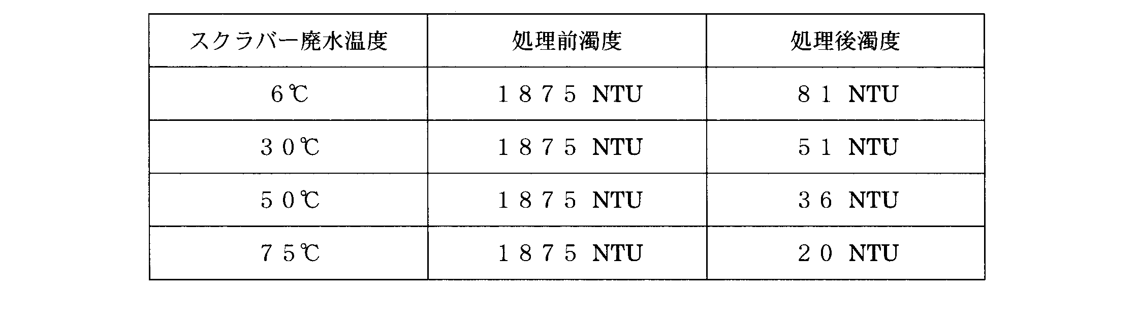
以上のとおり、重力を用いた廃水処理及び遠心力を用いた廃水処理のいずれにおいても、スクラバー廃水の温度が高くなるに従って、処理能力が向上することが確認できた。よって、本実施形態に係る廃水処理システム1によれば、加熱装置2によってスクラバー廃水を加熱し、その温度を装置保温部55によって維持したまま廃水処理装置32で廃水処理を行うため、非常に効率よくばいじんを除去することができる。
このように、DLVO理論に反し、スクラバー廃水の温度が上昇すると廃水処理の能力が向上するという結果が得られたが、これは粒子のブラウン運動が関与しているのではないかと発明者らは推測する。つまり、粒子の運動エネルギE3は下記の第4式で表されるが、水の絶対温度Tが上昇すると、粒子の運動エネルギE3も上昇する。これにより粒子のブラウン運動が活発になると、粒子同士の衝突回数が増加して凝集しやすくなると考えられる。つまり、粒子間斥力エネルギE1による影響よりも、粒子の運動エネルギE3による影響が勝り、粒子の凝集性が向上したと考えられる。その結果、スクラバー廃水の温度が上昇すると廃水処理の能力が向上したと推測する。

(第5実施形態)
次に、第5実施形態について説明する。図13は、本実施形態に係るエンジンシステムのブロック図である。図13に示すように、本実施形態に係る排気再循環ユニット30は、調整バルブ36を有している。
次に、第5実施形態について説明する。図13は、本実施形態に係るエンジンシステムのブロック図である。図13に示すように、本実施形態に係る排気再循環ユニット30は、調整バルブ36を有している。
調整バルブ36は、洗浄集じん装置31に供給された洗浄水の流量を調整し、ひいてはスクラバー廃水の温度を調整するバルブである。上述したように、洗浄集じん装置31では洗浄水により排気が洗浄されるが、その際に排水と洗浄水(スクラバー廃水)との間で熱交換が行われる。つまり、洗浄集じん装置31内において、洗浄水(スクラバー廃水)が、排気が有する熱によって加熱される。このとき、調整バルブ36により、洗浄水の流量を増やせばスクラバー廃水の上昇温度は小さくなり、洗浄水の流量を減らせばスクラバー廃水の上昇温度は大きくなる。このように、調整バルブ36を調整することで、加熱後のスクラバー廃水の温度を任意に設定することができる。なお、温度センサー(不図示)を例えば洗浄集じん装置31の下流に設置し、この温度センサーから取得したスクラバー廃水の温度に基づいて、調整バルブ36の開度が調整されるように構成してもよい。
スクラバー廃水の温度が高ければ、廃水処理の能力が向上する傾向にあるが、表2等に示すように、少なくとも75゜C程度にまで加熱すれば、廃水処理装置32は十分高い能力を発揮することができる。よって、スクラバー廃水は75゜C以上に加熱するのが好ましい。なお、スクラバー廃水が蒸発してしまっては排気再循環ユニット30が成り立たなくなるため、実質的にスクラバー廃水の温度は100゜C未満に抑える必要がある。
なお、洗浄集じん装置31と廃水処理装置32を連結する連結部37は、配管のみで構成されていてもよいが、スクラバー廃水へ凝集剤を添加するためや、バッファの役割を果たすためのタンクを有していても良い。また、連結部37の外表面には連結部保温部56が取り付けられている。連結部37にタンクが含まれている場合は、このタンクにも連結部保温部56が取り付けられる。連結部保温部56は、装置保温部55と同様に、公知の断熱部材によって形成され、連結部37内のスクラバー廃水を保温することができる。なお、連結部保温部56は、二重構造となるように構成されていてもよく、スクラバー廃水に熱を加えることができるよう構成されていてもよい。このように、連結部37に連結部保温部56を取り付けることで、加熱装置2で加熱されたスクラバー廃水を所望の温度に維持したまま廃水処理装置32に供給することができる。
以上が第4実施形態及び第5実施形態に係る排気再循環ユニット30の説明である。第4実施形態で説明したように、スクラバー廃水からばいじんを分離して取り除く廃水処理装置を利用する場合、スクラバー廃水を加熱することで、その処理能力を向上させることができる。そして、第5実施形態では、洗浄集じん装置31においてスクラバー廃水を所定温度以上に加熱し、加熱したスクラバー廃水を連結部保温部56によって保温しながら廃水処理装置32に供給し、高い温度を維持したまま廃水処理装置32でスクラバー廃水を処理している。そのため、非常に効率よくスクラバー廃水からばいじんを除去することができる。
また、第5実施形態の洗浄集じん装置31は、スクラバー廃水を加熱するものであるから、第4実施形態の加熱装置2に相当する。このように、洗浄集じん装置31が加熱装置2に相当するから、第5実施形態に係る排気再循環ユニット30は、第4実施形態に係る廃水処理システム1を含んでいるといえる。
第4実施形態及び第5実施形態では廃水処理装置32が、沈殿分離部40と遠心分離部60を含む場合について説明したが、これに代えてフィルタを用いた分離部を用いても良い。スクラバー廃水の温度が上昇すると、ばいじんの凝集が促されるため、フィルタを用いた分離部であっても廃水処理の能力は向上する。
以上、本発明の実施形態について図を参照して説明したが、具体的な構成はこれらの実施形態に限られるものではなく、この発明の要旨を逸脱しない範囲の設計の変更等があっても本発明に含まれる。
本発明に係る廃水処理装置は、小さなエネルギで稼動でき、メンテナンスが容易で、設置スペースを小さくでき、しかもスクラバー廃水からばいじんを精度よく除去することができる。よって、廃水処理装置の技術分野において有益である。
1 廃水処理システム
2 加熱装置
10 ディーゼルエンジン
30 排気再循環ユニット
31 洗浄集じん装置
32 廃水処理装置
37 連結部
40 沈殿分離部
41 水槽
47 傾斜管
48 傾斜面
50 流出ポート
51 天板部
52 第1液柱管
53 第2液柱管
54 エア抜き弁
55 装置保温部
56 連結部保温部
60 遠心分離部
70 振動手段
100 船舶
101 エンジンシステム
2 加熱装置
10 ディーゼルエンジン
30 排気再循環ユニット
31 洗浄集じん装置
32 廃水処理装置
37 連結部
40 沈殿分離部
41 水槽
47 傾斜管
48 傾斜面
50 流出ポート
51 天板部
52 第1液柱管
53 第2液柱管
54 エア抜き弁
55 装置保温部
56 連結部保温部
60 遠心分離部
70 振動手段
100 船舶
101 エンジンシステム
Claims (15)
- ばいじんを含有するスクラバー廃水からばいじんを除去する廃水処理装置であって、
水平方向に対して所定の角度をなす傾斜面を有し、該傾斜面にばいじんを沈殿させて前記スクラバー廃水からばいじんを分離する沈殿分離部と、
前記沈殿分離部の下流に配置され、遠心分離処理により前記スクラバー廃水からばいじんを分離する遠心分離部と、を備えた廃水処理装置。 - ディーゼルエンジンの排気を該ディーゼルエンジンに戻す排気再循環ユニットであって、
前記排気を洗浄してスクラバー廃水を排水する洗浄集じん装置と、
前記洗浄集じん装置から排出されたスクラバー廃水からばいじんを除去する請求項1に記載の廃水処理装置と、を備えた排気再循環ユニット。 - ばいじんを含有するスクラバー廃水からばいじんを除去する廃水処理装置であって、
ばいじんを沈殿させて前記スクラバー廃水からばいじんを分離する沈殿分離部を備え、
前記沈殿分離部は、
前記スクラバー廃水が流入する水槽と、
前記水槽の内部であって下端部分が前記水槽の底面よりも上方に位置するように配置され、前記スクラバー廃水が通過する複数の傾斜管と、
前記複数の傾斜管を振動させる振動手段と、を有する廃水処理装置。 - 前記水槽は、
前記傾斜管の上方に位置する天板部と、
前記天板部から上方に向かって延びる液柱管と、を有し、
前記スクラバー廃水の水面が前記液柱管内に位置するよう構成されている、請求項3に記載の廃水処理装置。 - 前記液柱管には、前記傾斜管を通過したスクラバー廃水を排出する流出ポートが形成されている、請求項4に記載の廃水処理装置。
- 前記水槽は、前記液柱管に取り付けられ、手動又は自動で前記水槽内の空気を排出することができるエア抜き弁をさらに有する、請求項5に記載の廃水処理装置。
- ディーゼルエンジンの排気を該ディーゼルエンジンに戻す排気再循環ユニットであって、
前記排気を洗浄してスクラバー廃水を排出する洗浄集じん装置と、
前記洗浄集じん装置から排出されたスクラバー廃水からばいじんを除去する請求項3乃至6のうちいずれか一の項に記載の廃水処理装置と、を備え、
前記振動手段は、前記ディーゼルエンジンの運転時に生じる振動を振動源として、前記複数の傾斜管を振動させる排気再循環ユニット。 - ディーゼルエンジンと、該ディーゼルエンジンの排気を該ディーゼルエンジンに戻す排気再循環ユニットと、を有するエンジンシステムを備えた船舶であって、
前記排気再循環ユニットは、
前記排気を洗浄してスクラバー廃水を排出する洗浄集じん装置と、
前記洗浄集じん装置から排出されたスクラバー廃水からばいじんを除去する請求項3乃至6のうちいずれか一の項に記載の廃水処理装置と、を有し、
前記振動手段は、運行時に生じる揺れを振動源として、前記複数の傾斜管を振動させる船舶。 - ばいじんを含有するスクラバー廃水からばいじんを分離して取り除く廃水処理装置を備え、ばいじんを含有する前、含有する際、及び含有した後の少なくともいずれかのタイミングで前記スクラバー廃水を所定温度以上に加熱し、加熱したスクラバー廃水を前記廃水処理装置に供給するよう構成されている、廃水処理システム。
- ディーゼルエンジンの排気を該ディーゼルエンジンに戻す排気再循環ユニットであって、
前記排気を洗浄してスクラバー廃水を排水する洗浄集じん装置と、
前記スクラバー廃水からばいじんを分離して取り除く廃水処理装置と、を備え、
前記洗浄集じん装置内において、前記排気が有する熱によって前記スクラバー廃水を所定温度以上に加熱し、加熱したスクラバー廃水を前記廃水処理装置に供給するよう構成されている、排気再循環ユニット。 - 前記洗浄集じん装置と前記廃水処理装置を連結する連結部と、
前記連結部内のスクラバー廃水を保温する連結部保温部と、をさらに備える請求項10に記載の排気再循環ユニット。 - 前記廃水処理装置内のスクラバー廃水を保温する装置保温部をさらに備える、請求項10又は11に記載の排気再循環ユニット。
- 前記洗浄集じん装置内で前記スクラバー廃水を75゜C以上に加熱する、請求項10乃至12のうちいずれか一の項に記載の排気再循環ユニット。
- ディーゼルエンジンと、請求項2、7、10乃至13のうちいずれか一の項に記載の排気再循環ユニットと、を備えたエンジンシステム。
- 請求項14に記載のエンジンシステムを備えた船舶。
Priority Applications (5)
| Application Number | Priority Date | Filing Date | Title |
|---|---|---|---|
| CN201380028803.1A CN104334247B (zh) | 2012-06-11 | 2013-06-10 | 废水处理装置、排气再循环单元、发动机系统及船舶 |
| KR1020177005318A KR20170026637A (ko) | 2012-06-11 | 2013-06-10 | 폐수 처리 장치, 폐수 처리 시스템, 배기 재순환 유닛, 엔진 시스템, 및 선박 |
| EP13804879.8A EP2862608A4 (en) | 2012-06-11 | 2013-06-10 | WASTEWATER TREATMENT DEVICE, WASTEWATER TREATMENT SYSTEM, EXHAUST GAS RECIRCULATION UNIT, ENGINE SYSTEM AND SHIP |
| KR1020157000364A KR101786815B1 (ko) | 2012-06-11 | 2013-06-10 | 폐수 처리 장치, 폐수 처리 시스템, 배기 재순환 유닛, 엔진 시스템, 및 선박 |
| KR1020177014354A KR20170061195A (ko) | 2012-06-11 | 2013-06-10 | 폐수 처리 장치, 폐수 처리 시스템, 배기 재순환 유닛, 엔진 시스템, 및 선박 |
Applications Claiming Priority (6)
| Application Number | Priority Date | Filing Date | Title |
|---|---|---|---|
| JP2012-132293 | 2012-06-11 | ||
| JP2012-132294 | 2012-06-11 | ||
| JP2012132293A JP5843701B2 (ja) | 2012-06-11 | 2012-06-11 | 廃水処理装置、排気再循環ユニット、エンジンシステム、及び船舶 |
| JP2012132295A JP5798087B2 (ja) | 2012-06-11 | 2012-06-11 | 廃水処理システム、排気再循環ユニット、エンジンシステム、及び船舶 |
| JP2012-132295 | 2012-06-11 | ||
| JP2012132294A JP5843702B2 (ja) | 2012-06-11 | 2012-06-11 | 廃水処理装置、排気再循環ユニット、エンジンシステム、及び船舶 |
Publications (1)
| Publication Number | Publication Date |
|---|---|
| WO2013187038A1 true WO2013187038A1 (ja) | 2013-12-19 |
Family
ID=49757884
Family Applications (1)
| Application Number | Title | Priority Date | Filing Date |
|---|---|---|---|
| PCT/JP2013/003628 WO2013187038A1 (ja) | 2012-06-11 | 2013-06-10 | 廃水処理装置、廃水処理システム、排気再循環ユニット、エンジンシステム、及び船舶 |
Country Status (4)
| Country | Link |
|---|---|
| EP (1) | EP2862608A4 (ja) |
| KR (3) | KR20170026637A (ja) |
| CN (1) | CN104334247B (ja) |
| WO (1) | WO2013187038A1 (ja) |
Cited By (1)
| Publication number | Priority date | Publication date | Assignee | Title |
|---|---|---|---|---|
| CN113479312A (zh) * | 2021-06-24 | 2021-10-08 | 上海江南长兴造船有限责任公司 | 一种用于双燃料主机燃气透气出口的密封油收集装置 |
Families Citing this family (8)
| Publication number | Priority date | Publication date | Assignee | Title |
|---|---|---|---|---|
| FR3056412B1 (fr) * | 2016-09-29 | 2021-02-19 | Lab Sa | Procede d'epuration des effluents liquides d'un laveur humide de traitement de fumees d'echappement emises par un moteur diesel, ainsi que procede de traitement de telles fumees |
| JP6378739B2 (ja) * | 2016-11-18 | 2018-08-22 | 川崎重工業株式会社 | 大型船舶用のエンジンシステム |
| DE102017115193A1 (de) * | 2017-07-06 | 2019-01-10 | Bilfinger Engineering & Technologies Gmbh | Rauchgasreinigungsvorrichtung und Verfahren zur Reinigung von Rauchgasen auf Schiffen |
| KR20190007599A (ko) | 2017-07-13 | 2019-01-23 | 반병훈 | 세차장용 폐수 처리 장치 및 방법 |
| CN108945293B (zh) * | 2018-07-27 | 2021-03-30 | 广船国际有限公司 | 一种船舶机舱临时通风方法 |
| KR20190018461A (ko) | 2019-02-13 | 2019-02-22 | 반병훈 | 세차장용 폐수 처리 장치 및 방법 |
| JP6849849B1 (ja) * | 2020-09-08 | 2021-03-31 | 株式会社三井E&Sマシナリー | 船舶排ガスの洗浄排水処理装置 |
| CN112642248B (zh) * | 2020-12-18 | 2022-08-02 | 四川宏华石油设备有限公司 | 一种页岩气高效除砂装置、除砂系统及除砂方法 |
Citations (11)
| Publication number | Priority date | Publication date | Assignee | Title |
|---|---|---|---|---|
| JPS5128263A (ja) * | 1974-09-03 | 1976-03-10 | Kajima Doro Kk | |
| JPS5325973A (en) * | 1976-08-21 | 1978-03-10 | Kobe Steel Ltd | Method and device for separating accompanied carbon continually |
| JPS6279814A (ja) * | 1985-10-01 | 1987-04-13 | Kawasaki Heavy Ind Ltd | 傾斜沈降装置の洗浄方法および装置 |
| JPH07189658A (ja) * | 1993-12-28 | 1995-07-28 | Katsuro Yashima | 排ガス処理装置 |
| JPH08511074A (ja) * | 1993-06-04 | 1996-11-19 | マーン・ベー・オグ・ドバルドヴェー・ディーゼール・アクティーゼルスカブ | 大型過給ディーゼルエンジン |
| JP2001276844A (ja) | 2000-03-29 | 2001-10-09 | Yoshikimi Watanabe | 造水方法および造水システム |
| JP2002346581A (ja) | 2001-05-28 | 2002-12-03 | Yoshikimi Watanabe | 有機性廃水の処理装置および処理方法 |
| JP2003502138A (ja) * | 1999-06-22 | 2003-01-21 | テルモゼレクト・アクチェンゲゼルシャフト | 分離装置及びその使用方法 |
| JP2004034018A (ja) * | 2001-08-09 | 2004-02-05 | Vidal Fernandez Rafael | 塗装装置および塗装方法 |
| JP2004081933A (ja) | 2002-08-23 | 2004-03-18 | Mitsubishi Heavy Ind Ltd | 排水処理装置 |
| WO2011104302A1 (en) * | 2010-02-25 | 2011-09-01 | Alfa Laval Corporate Ab | Exhaust gas and gas scrubber fluid cleaning equipment and method |
Family Cites Families (9)
| Publication number | Priority date | Publication date | Assignee | Title |
|---|---|---|---|---|
| SE341575B (ja) * | 1969-11-05 | 1972-01-10 | Alfa Laval Ab | |
| US4221671A (en) * | 1979-02-26 | 1980-09-09 | Meurer Charles L | Upright circular tube settler with stacked tube modules |
| GB2163417A (en) * | 1984-08-22 | 1986-02-26 | Mitsubishi Heavy Ind Ltd | Controlling slurry concentration in wet flue gas desulphurization apparatus |
| US5213782A (en) * | 1991-11-22 | 1993-05-25 | Electric Power Research Institute | Clear liquor scrubbing magnesium-enhanced lime flue gas desulfurization process |
| CN1176839A (zh) * | 1996-09-16 | 1998-03-25 | 阎洪波 | 脉冲澄清池水处理装置 |
| CN2354627Y (zh) * | 1998-06-22 | 1999-12-22 | 邵英倚 | 静止沉淀槽 |
| JP2006061754A (ja) * | 2004-08-24 | 2006-03-09 | Aquatech:Kk | フッ素含有廃水の処理方法およびフッ素含有廃水の処理設備 |
| CN100441527C (zh) * | 2006-03-31 | 2008-12-10 | 王涛 | 冶金工业冷轧中和站酸性废水的处理方法 |
| US8128786B2 (en) * | 2009-03-02 | 2012-03-06 | Harris Corporation | RF heating to reduce the use of supplemental water added in the recovery of unconventional oil |
-
2013
- 2013-06-10 KR KR1020177005318A patent/KR20170026637A/ko not_active Application Discontinuation
- 2013-06-10 KR KR1020157000364A patent/KR101786815B1/ko active IP Right Grant
- 2013-06-10 CN CN201380028803.1A patent/CN104334247B/zh not_active Expired - Fee Related
- 2013-06-10 EP EP13804879.8A patent/EP2862608A4/en not_active Withdrawn
- 2013-06-10 WO PCT/JP2013/003628 patent/WO2013187038A1/ja active Application Filing
- 2013-06-10 KR KR1020177014354A patent/KR20170061195A/ko active Search and Examination
Patent Citations (11)
| Publication number | Priority date | Publication date | Assignee | Title |
|---|---|---|---|---|
| JPS5128263A (ja) * | 1974-09-03 | 1976-03-10 | Kajima Doro Kk | |
| JPS5325973A (en) * | 1976-08-21 | 1978-03-10 | Kobe Steel Ltd | Method and device for separating accompanied carbon continually |
| JPS6279814A (ja) * | 1985-10-01 | 1987-04-13 | Kawasaki Heavy Ind Ltd | 傾斜沈降装置の洗浄方法および装置 |
| JPH08511074A (ja) * | 1993-06-04 | 1996-11-19 | マーン・ベー・オグ・ドバルドヴェー・ディーゼール・アクティーゼルスカブ | 大型過給ディーゼルエンジン |
| JPH07189658A (ja) * | 1993-12-28 | 1995-07-28 | Katsuro Yashima | 排ガス処理装置 |
| JP2003502138A (ja) * | 1999-06-22 | 2003-01-21 | テルモゼレクト・アクチェンゲゼルシャフト | 分離装置及びその使用方法 |
| JP2001276844A (ja) | 2000-03-29 | 2001-10-09 | Yoshikimi Watanabe | 造水方法および造水システム |
| JP2002346581A (ja) | 2001-05-28 | 2002-12-03 | Yoshikimi Watanabe | 有機性廃水の処理装置および処理方法 |
| JP2004034018A (ja) * | 2001-08-09 | 2004-02-05 | Vidal Fernandez Rafael | 塗装装置および塗装方法 |
| JP2004081933A (ja) | 2002-08-23 | 2004-03-18 | Mitsubishi Heavy Ind Ltd | 排水処理装置 |
| WO2011104302A1 (en) * | 2010-02-25 | 2011-09-01 | Alfa Laval Corporate Ab | Exhaust gas and gas scrubber fluid cleaning equipment and method |
Non-Patent Citations (1)
| Title |
|---|
| See also references of EP2862608A4 * |
Cited By (1)
| Publication number | Priority date | Publication date | Assignee | Title |
|---|---|---|---|---|
| CN113479312A (zh) * | 2021-06-24 | 2021-10-08 | 上海江南长兴造船有限责任公司 | 一种用于双燃料主机燃气透气出口的密封油收集装置 |
Also Published As
| Publication number | Publication date |
|---|---|
| KR20170026637A (ko) | 2017-03-08 |
| KR101786815B1 (ko) | 2017-10-18 |
| KR20150016633A (ko) | 2015-02-12 |
| KR20170061195A (ko) | 2017-06-02 |
| EP2862608A4 (en) | 2016-07-13 |
| CN104334247B (zh) | 2018-12-07 |
| CN104334247A (zh) | 2015-02-04 |
| EP2862608A1 (en) | 2015-04-22 |
Similar Documents
| Publication | Publication Date | Title |
|---|---|---|
| WO2013187038A1 (ja) | 廃水処理装置、廃水処理システム、排気再循環ユニット、エンジンシステム、及び船舶 | |
| JP5968954B2 (ja) | 排ガス及びガス・スクラバ流体浄化装置及び方法 | |
| JP5843701B2 (ja) | 廃水処理装置、排気再循環ユニット、エンジンシステム、及び船舶 | |
| EP2402288B1 (en) | Cleaning equipment for gas scrubber fluid | |
| US20050016937A1 (en) | Separator of floating components | |
| JP5798087B2 (ja) | 廃水処理システム、排気再循環ユニット、エンジンシステム、及び船舶 | |
| JP2011525850A (ja) | 混合比調節器と電動逆洗フィルターホモジナイザーを用いた混合油インライン製造装置 | |
| TW201325686A (zh) | 用於燃料過濾之裝置和方法 | |
| JP2015073983A (ja) | 船舶の機関室ビルジ処理システム | |
| CN106988832B (zh) | 尾气颗粒物捕集装置及其控制方法 | |
| JP5843702B2 (ja) | 廃水処理装置、排気再循環ユニット、エンジンシステム、及び船舶 | |
| KR101976867B1 (ko) | 연료공급라인의 연료 필터링 장치 | |
| JP6810582B2 (ja) | 廃水処理システム | |
| KR101808813B1 (ko) | 원형 가압부상장치를 이용한 스크러버 배출수 처리 시스템 및 방법 | |
| JP2021510795A (ja) | 燃料システム | |
| KR100933941B1 (ko) | 자동식 액체연료 여과장치 | |
| RU2687461C1 (ru) | Способ очистки нефтесодержащих вод и устройство для его осуществления | |
| KR102044853B1 (ko) | 중력을 이용한 무동력 분리기 | |
| KR101064027B1 (ko) | 선박용 연료 저질중유의 정제 및 공급장치 | |
| RU2377045C1 (ru) | Фильтр-грязевик инерционный щелевой | |
| CN217148866U (zh) | 一种环保工程用高效的油水分离装置 | |
| RU2321547C2 (ru) | Нефтеводяной центробежно-фильтрующий сепаратор | |
| RU2221624C1 (ru) | Сепаратор для очистки дизельных топлив | |
| EA002640B1 (ru) | Способ очистки воды от жидких нефтепродуктов и нефтеводяной центробежно-фильтрующий сепаратор с электростатической очисткой воды | |
| RU59996U1 (ru) | Фильтрующий патрон |
Legal Events
| Date | Code | Title | Description |
|---|---|---|---|
| 121 | Ep: the epo has been informed by wipo that ep was designated in this application |
Ref document number: 13804879 Country of ref document: EP Kind code of ref document: A1 |
|
| NENP | Non-entry into the national phase |
Ref country code: DE |
|
| ENP | Entry into the national phase |
Ref document number: 20157000364 Country of ref document: KR Kind code of ref document: A |
|
| REEP | Request for entry into the european phase |
Ref document number: 2013804879 Country of ref document: EP |