WO2013183646A1 - アルミノホウケイ酸ガラスを原料とするa型ゼオライトの製造方法 - Google Patents
アルミノホウケイ酸ガラスを原料とするa型ゼオライトの製造方法 Download PDFInfo
- Publication number
- WO2013183646A1 WO2013183646A1 PCT/JP2013/065493 JP2013065493W WO2013183646A1 WO 2013183646 A1 WO2013183646 A1 WO 2013183646A1 JP 2013065493 W JP2013065493 W JP 2013065493W WO 2013183646 A1 WO2013183646 A1 WO 2013183646A1
- Authority
- WO
- WIPO (PCT)
- Prior art keywords
- glass
- producing
- type zeolite
- aluminoborosilicate glass
- synthesis
- Prior art date
- Legal status (The legal status is an assumption and is not a legal conclusion. Google has not performed a legal analysis and makes no representation as to the accuracy of the status listed.)
- Ceased
Links
Images











Classifications
-
- B—PERFORMING OPERATIONS; TRANSPORTING
- B09—DISPOSAL OF SOLID WASTE; RECLAMATION OF CONTAMINATED SOIL
- B09B—DISPOSAL OF SOLID WASTE NOT OTHERWISE PROVIDED FOR
- B09B3/00—Destroying solid waste or transforming solid waste into something useful or harmless
- B09B3/30—Destroying solid waste or transforming solid waste into something useful or harmless involving mechanical treatment
- B09B3/35—Shredding, crushing or cutting
-
- B—PERFORMING OPERATIONS; TRANSPORTING
- B09—DISPOSAL OF SOLID WASTE; RECLAMATION OF CONTAMINATED SOIL
- B09B—DISPOSAL OF SOLID WASTE NOT OTHERWISE PROVIDED FOR
- B09B3/00—Destroying solid waste or transforming solid waste into something useful or harmless
- B09B3/70—Chemical treatment, e.g. pH adjustment or oxidation
-
- C—CHEMISTRY; METALLURGY
- C01—INORGANIC CHEMISTRY
- C01B—NON-METALLIC ELEMENTS; COMPOUNDS THEREOF; METALLOIDS OR COMPOUNDS THEREOF NOT COVERED BY SUBCLASS C01C
- C01B33/00—Silicon; Compounds thereof
- C01B33/02—Silicon
-
- C—CHEMISTRY; METALLURGY
- C01—INORGANIC CHEMISTRY
- C01B—NON-METALLIC ELEMENTS; COMPOUNDS THEREOF; METALLOIDS OR COMPOUNDS THEREOF NOT COVERED BY SUBCLASS C01C
- C01B39/00—Compounds having molecular sieve and base-exchange properties, e.g. crystalline zeolites; Their preparation; After-treatment, e.g. ion-exchange or dealumination
- C01B39/02—Crystalline aluminosilicate zeolites; Isomorphous compounds thereof; Direct preparation thereof; Preparation thereof starting from a reaction mixture containing a crystalline zeolite of another type, or from preformed reactants; After-treatment thereof
- C01B39/14—Type A
- C01B39/18—Type A from a reaction mixture containing at least one aluminium silicate or aluminosilicate of a clay type, e.g. kaolin or metakaolin or its exotherm modification or allophane
Definitions
- the present invention relates to a method for producing A-type zeolite using aluminoborosilicate glass as a raw material.
- liquid crystal panel refers to one in which a liquid crystal material is injected and sealed inside two bonded glass substrates, and a polarizing plate (resin) is bonded to the outside of each glass substrate.
- polarizing plate resin
- liquid crystal display devices and liquid crystal panels contained in waste such as home appliances and information equipment are small in amount of waste, and after being crushed for each product in a waste treatment facility, plastic Along with shredder dust containing a large amount of waste, it is landfilled or incinerated.
- Patent Document discloses a defective waste liquid crystal panel discharged from a liquid crystal panel manufacturing factory, a liquid crystal display device contained in wastes such as home appliances and information equipment, and a method for treating the liquid crystal panel. 1) discloses a method in which products are crushed at a liquid crystal panel manufacturing plant or waste disposal facility, and then put into a non-ferrous smelting furnace and treated as an alternative material for silica. . In this method, the glass component in the liquid crystal panel enters the slag.
- Patent Document 2 discloses a method for producing ceramic products such as tiles, bricks and various blocks using glass waste, clay, and ceramic waste as raw materials. Yes.
- a composition of 100% by weight in total is composed of 50 to 80% by weight of ground glass waste, 10 to 45% by weight of clay, and 5 to 40% by weight of ground ceramic waste. This is a method of adjusting, shaping, drying, and firing at 1000 to 1200 ° C.
- Patent Document 3 discloses low-temperature fired glass ceramics using as raw materials soda-lime glass fine powder, CaO-containing compound fine powder, and B 2 O 3- compound fine powder. The manufacturing method is described. In the method described in Patent Document 3, the above compound is mixed, the mixture is press-molded into a required shape, and the molded product is fired at a temperature range of 825 to 900 ° C. It is a manufacturing method.
- Patent Document 4 JP-A-59-35019 discloses a method for producing zeolite from coal ash produced from a fluidized bed combustion furnace for coal.
- the method described in Patent Document 4 was obtained by adding and blending an alumina source, an alkali source, and water as raw materials so that the silica / alumina, water / alkali, and alkali / alumina ratio was a predetermined molar ratio.
- This is a method for synthesizing zeolite synthesized using a raw material component mixture under hydrothermal conditions.
- Patent Document 5 discloses a method for producing a zeolite composition using fly ash, which is a fuel residue of a coal-fired boiler, as a raw material.
- the method described in Patent Document 5 is a method for producing a zeolite composition by blending and kneading a raw material with a 0.5N to 3N NaOH solution and performing autoclave treatment at a pressure of 3.0 kg / cm 2 or more.
- Patent Document 6 discloses a method for producing a zeolite composition using a granulated slag powder as a raw material.
- a granulated slag powder is dissolved in an inorganic acid aqueous solution and then ammonia gas is blown to adjust the pH to 4 to 9 (silica and alumina are the main components.
- This is a method in which the calcium content is filtered off and the zeolite is synthesized by hydrothermal synthesis by adding an alkali metal hydroxide to the precipitate.
- Patent Document 7 JP 2007-131502 A discloses a method for producing zeolite using ceramics, concrete, debris, glass and a mixture thereof as raw materials.
- a mixture obtained by adding and mixing a solid base to a raw material is heated and melted to produce a powder in which Si and Al are readily soluble in water.
- This is a method for producing zeolite in which the obtained powder is added to water and reacted at a reaction temperature of 20 to 200 ° C.
- Patent Document 8 discloses a porous fine particle whose surface is zeoliticized by directly reacting a silica raw material heated to a high temperature with an aqueous solution of an aluminum salt in the air.
- a method of manufacturing is disclosed. Use waste soda-lime glass, steel slag, granulated slag, etc. that are problematic as a silica raw material, heat it to a high temperature state, and add a component that is lacking as a zeolite component in the form of an aqueous solution.
- This is a production method in which spraying, quenching and reaction are performed to reduce the particle size of the raw material to increase the surface area, and to zeolitize the surface of the raw material instead of the whole.
- Patent Document 9 discloses a method for crystallizing zeolite on the surface of a monolithic ceramic support.
- a monolithic ceramic (cordierite) support having an oxide composition consisting of 45-75% by weight silica, 8-45% by weight alumina and 7-20% by weight magnesia is treated with sodium oxide or sodium hydroxide, alumina, and optionally And a hydrothermal treatment at a temperature sufficient to crystallize the desired zeolite on the surface of the support together with an aqueous solution containing active silica.
- a monolithic ceramic support is coated with a layer of active silica (the coating is 1-45% by weight of the coated support) and the active silica is crystallized into the desired zeolite to form the surface of the support.
- the zeolite it is hydrothermally treated with an aqueous solution containing sodium oxide or sodium hydroxide and alumina.
- a hydrothermal treatment of a sintered monolithic body containing porous ceramic material and 1-40% total weight of active silica embedded in the ceramic material with an aqueous solution containing sodium oxide or sodium hydroxide and optionally alumina is crystallized on the surface of the monolithic body.
- JP 2000-84531 A JP 2000-351664 A JP 2002-308646 A JP 59-35019 A JP-A 64-24014 JP 58-120512 A JP 2007-131502 A JP 2006-45042 A Japanese Patent Laid-Open No. 1-148771
- the LCD panel is a display device that can contribute to power and resource savings, it is predicted that the production volume will increase rapidly and the display area will increase with the progress of the advanced information society. Along with this, the number and amount of waste liquid crystal panels are expected to increase rapidly in the future. Therefore, glass (liquid crystal panel glass) occupying most of the weight of the liquid crystal panel is preferably recycled from the viewpoint of reducing waste and valuing resources.
- the method disclosed in Patent Document 1 is intended to be reused as a cement material, the liquid crystal panel glass becomes slag and cannot be recycled as the glass itself.
- aluminoborosilicate glass is usually used for the liquid crystal panel glass.
- Aluminoborosilicate glass is a special glass made to be compatible with the manufacturing process of liquid crystal panels, and has a strain point of 650 ° C. or higher.
- the strain point of soda lime glass widely used for glass products such as bottle glass, architectural window glass, glass fiber, and tableware glass is 550 ° C. or lower.
- the strain points are different by 100 ° C. or more, it is a heating facility to melt aluminoborosilicate glass for recycling in a soda lime glass melting processing facility generally used for glass products. It is very difficult in terms of performance and heat resistance of the overall equipment.
- aluminoborosilicate glass with a high melting temperature for general-purpose products such as architectural window glass, glass fiber, and tableware glass that usually uses soda-lime glass as a raw material. It becomes.
- the present condition is that the method used for the use as a raw material of a normal soda-lime glass product is not technically established. For this reason, as a use of liquid crystal panel glass that has become unnecessary, there is a demand for a recycling method that is used for applications in which the processing temperature does not increase compared to the temperature of the current manufacturing process.
- Patent Document 2 The method described in Patent Document 2 described above is a method in which pulverized glass waste is used as a main raw material, and ceramic waste pulverized in this is used as a raw material, followed by heating and baking at a high temperature of 1000 to 1200 ° C.
- the method disclosed in Patent Document 2 undergoes a high-temperature firing step, there is a problem that a great amount of energy is consumed as a recycling method. Therefore, energy cost and equipment cost increase, and the obtained ceramic product becomes expensive.
- Patent Document 3 The method described in Patent Document 3 described above is a method of firing a mixture of compounds using crushed soda-lime glass waste as a main raw material at 825 to 900 ° C.
- the method disclosed in Patent Document 3 is a method for preparing a ceramic material by preparing and crystallizing soda lime glass waste to a composition corresponding to the soda lime glass waste, and for application to aluminoborosilicate glass. It is not described.
- Patent Document 4 uses ashes raw material from a fluidized bed combustion furnace for coal.
- the ash produced by the combustion of coal is the one in which the inorganic components contained in the coal remain in a baked state, mainly composed of Al 2 O 3 and SiO 2 , and the Al 2 O 3 / SiO 2 ratio is 2-5.
- the synthesis rate of zeolite is low, and the synthesis rate varies due to variations in the raw material composition depending on the origin of the raw material coal. In each case, it is necessary to prepare the composition.
- the method described in Patent Document 5 described above is a method for producing a zeolite composition using fly ash, which is a fuel residue of a coal-fired boiler, as a raw material.
- fly ash is coal ash that has been quenched and vitrified after melting in a boiler, has a high melting point, is hard and stable, and thus has a problem that it is difficult to react.
- a pretreatment such as melting at a high temperature is required, resulting in poor efficiency.
- Patent Document 6 The method described in Patent Document 6 described above is a method for producing zeolite using granulated slag as a raw material.
- slag is used as a raw material as in the method disclosed in Patent Document 6, since the slag contains a large amount of Ca that inhibits zeolitization, a treatment for removing Ca, such as acid treatment, is required, resulting in poor efficiency.
- acid treatment a treatment for removing Ca, such as acid treatment
- Patent Document 7 In the method described in Patent Document 7 described above, a raw material is mixed with a solid base, heated and dissolved at 200 to 1000 ° C., easily dissolved in water, and then subjected to hydrothermal synthesis at 20 to 200 ° C. It is a manufacturing method. However, the method disclosed in Patent Document 7 requires heating at a high temperature around 1000 ° C. and consumes a great deal of energy.
- Patent Document 8 The method described in Patent Document 8 described above is a method for producing a granulated body whose surface is zeoliticized.
- the reaction is performed by spraying an aqueous solution, the amount of zeolite produced (ratio) is reduced, and the problem is that the ion exchange capacity is lowered to 0.3 to 1 meq / g. Further, heating at a high temperature in the vicinity of 570 to 1000 ° C. is necessary, and a great amount of energy is consumed.
- Patent Document 9 The method described in Patent Document 9 described above is a method of crystallizing zeolite on the surface of a monolithic ceramic support.
- active silica it is necessary to add active silica to the aqueous solution during hydrothermal synthesis or to coat the monolithic ceramic support with active silica.
- this since it is necessary to uniformly mix the active silica with the ceramic and form it into a desired shape and then sinter at 500 to 850 ° C., this is a complicated process.
- a method for synthesizing zeolite from waste and a zeolitic material synthesized from waste are disclosed, but it is difficult to stably obtain a single A-type zeolite phase by either method. There is a problem that the crystal structure remains.
- a zeolite synthesis method using aluminoborosilicate glass recovered from a liquid crystal panel as a raw material and a synthesized zeolite material are not disclosed.
- the ion exchange performance which is a feature of the A-type zeolite, is deteriorated when compared with a high-purity A-type zeolite due to the presence of other phases.
- zeolite synthesized from coal ash, incinerated ash, slag, and the like contains heavy metals derived from raw material coal, ore, etc., and elution of heavy metals becomes a problem when zeolite is synthesized.
- the present invention has been made in order to solve the above-mentioned problems, and the object of the present invention is to provide a method for efficiently using the recovered alkali-free glass as a resource without consuming a great deal of energy. Furthermore, the present invention provides a method for producing an A-type zeolite material that is excellent in ion exchange capacity, can be used as a water purification material, a catalyst material, and the like and has no elution of heavy metals. Another object of the present invention is to provide a method for producing an A-type zeolitic material that is efficient and easily controllable.
- an object of the present invention is to provide a zeolitic material that is excellent in water permeability when packed in a column or the like and does not run away due to rainwater or the like when used as a soil modifier.
- the present invention is a method for producing an A-type zeolitic material by using aluminoborosilicate glass as a raw material and zeolitizing the surface layer portion, and includes a synthesis step of heat-treating a mixture of aluminoborosilicate glass and an alkaline solution. Is a method for producing an A-type zeolite material.
- the aluminoborosilicate glass is brought into contact with an acidic solution, and the surface layer of the aluminoborosilicate glass is compared with other regions of the aluminoborosilicate glass. It is preferable to include an acid treatment step of forming a region having a low calcium content and / or forming a region having a high SiO 2 content ratio as compared with other regions of aluminoborosilicate glass.
- the synthesis step is preferably a heat treatment of a mixture of aluminoborosilicate glass and an alkaline solution by hydrothermal treatment.
- an alkali treatment step in which the aluminoborosilicate glass is brought into contact with an alkaline solution is included between the acid treatment step and the synthesis step.
- the synthesis step comprises heating a mixture of aluminoborosilicate glass and an alkali solution to form an aluminosilicate gel and heating the aluminosilicate gel in contact with the glass surface layer. It is preferable to hold.
- the acid treatment step includes a preparation step of adding an aluminum compound so that the Si / Al molar ratio is 0.1 or more and 2.0 or less (more preferably 1 or less). It is preferable that it is further included between and the said synthetic
- the acid treatment step uses an acidic solution having a concentration of 0.1 to 10 N containing at least one selected from hydrochloric acid and nitric acid for 1 hour or more (more preferably It is preferable that it is a process to process for 5 hours or more.
- A-type zeolite material of the present invention it is preferable to use a material obtained by grinding the aluminoborosilicate glass to 50 to 700 ⁇ m.
- the synthesis step is preferably a step using an alkaline solution having a concentration of 0 to 3N (more preferably 0.2 to 3N).
- the synthesis step is preferably a step of performing a heat treatment at 75 to 150 ° C. (more preferably 80 to 110 ° C.) for 24 hours or more.
- the aluminoborosilicate glass preferably has a composition of SiO 2 : 50% by weight or more and Al 2 O 3 : 10 to 20% by weight.
- the aluminoborosilicate glass is preferably an aluminoborosilicate glass recovered from a liquid crystal panel.
- aluminoborosilicate glass recovered from a liquid crystal panel or the like that is no longer needed as a high-value-added zeolite material.
- a zeolite using an aluminoborosilicate glass that has become unnecessary can be produced without performing high-temperature melting or the like, and therefore, a production method with low environmental load and low cost is provided.
- the reaction can be controlled through a predetermined treatment, a zeolitic material having a surface layer of a single A-type zeolite that is excellent in ion exchange capacity and can be used as an adsorbent is synthesized.
- a method for producing an A-type zeolite material it is possible to provide a method for producing an A-type zeolite material.
- Glass can be used for water purification purposes in running water because it can change the pulverized particle size, and can be melt processed into an arbitrary shape such as foamed glass to form a zeolite support.
- zeoliticizing the surface of glass with a large particle size provides a material suitable for use as a soil modifier, etc., which can be used as a material having better water permeability than powdered zeolite. be able to.
- it is not necessary to reduce the pulverized particle size it is possible to provide a zeolitic material that can be manufactured at a low cost and in a short time while suppressing the pulverization cost and pulverization time.
- FIG. 1 is a SEM photograph showing an example of an A-type zeolite material obtained in Example 1.
- 3 is a graph showing an example of X-ray diffraction of the A-type zeolite material obtained in Example 2.
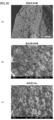
- FIGS. 10 (a), (b), and (c) are SEM photographs of the zeolite material when synthesized from glass that has been subjected to acid treatment for 3, 96 and 168 hours, respectively.
- FIG. 6 is a graph showing an example of X-ray diffraction of the A-type zeolite material obtained in Example 5.
- FIG. 6 is a SEM photograph showing an example of A-type zeolite material obtained in Example 5.
- FIG. 12 (a), (b), (c), and (d) are SEM photographs of the zeolitic material when the synthesis is performed for 48, 96, 168, and 336 hours, respectively.
- 6 is a graph showing an example of X-ray diffraction of the A-type zeolite material obtained in Example 6.
- FIG. 6 is an SEM photograph showing an example of an A-type zeolite material obtained in Example 6.
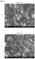
- 14A and 14B are SEM photographs of the zeolitic material when synthesized in 0.5 and 1.0 M NaOH solutions, respectively.
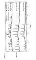
- 6 is a graph showing an example of X-ray diffraction of the zeolite material obtained in Example 7 and Comparative Example 1.
- 4 is a graph showing an example of X-ray diffraction of the zeolite material obtained in Example 8 and Comparative Example 2.
- 10 is a graph showing an example of X-ray diffraction of the A-type zeolite material obtained in Example 9. It is an example of the external appearance of the filtrate containing the aluminosilicate gel obtained from the glass which carried out the nitric acid process in Example 10.
- Example 10 It is an example of the X-ray diffraction of the product obtained by carrying out the hydrothermal treatment of the aluminosilicate gel in Example 10.
- 6 is a graph showing an example of X-ray diffraction of the A-type zeolite material obtained in Example 11.
- FIG. It is an example of the external appearance of the filtrate obtained from the glass which is not nitric acid processing in the comparative example 3.
- the method for producing an A-type zeolitic material using the aluminoborosilicate glass of the present invention is basically characterized by including a synthesis step of heat-treating a mixture of an aluminoborosilicate glass and an alkaline solution.
- the zeolitic material produced according to the present invention is characterized in that crushed aluminoborosilicate glass is used as a support and the surface layer portion is converted to A-type zeolite.
- a zeolite material (preferably an A-type zeolite) is produced using aluminoborosilicate glass as a raw material without subjecting it to a melting treatment at a high temperature.
- aluminoborosilicate glass used in liquid crystal panels and the like that are no longer necessary as a resource in a low environmental load process.
- aluminoborosilicate glass which is essentially unnecessary is used as a raw material and the raw glass is not melted at a high temperature, the energy consumption is small, and an inexpensive zeolitic material can be obtained with low equipment cost and energy cost.
- A-type zeolite single phase that is not mixed with impure phase on the surface layer of aluminoborosilicate glass so it can be used for high performance water purification agent, desiccant, molecular sieve, catalyst, etc. It is possible to produce a zeolitic material that can be produced.
- the aluminoborosilicate glass in the present invention preferably has a composition of SiO 2 : 50% by weight or more and Al 2 O 3 : 10 to 20% by weight.
- SiO 2 / Al 2 O 3 is 4.24 in molar ratio, that is, Si / Al molar ratio is in the range of 1 or more, and FAU type zeolite (Si / Al molar ratio: 1.5 to 3) And is suitable as a raw material for zeolite A (Si / Al molar ratio: 1).
- the aluminoborosilicate glass having such a composition can be confirmed by, for example, composition analysis using fluorescent X-ray analysis.
- the aluminoborosilicate glass used as a raw material in the present invention is an aluminoborosilicate glass used as a liquid crystal panel glass mounted on the liquid crystal display device. More preferably, the composition ranges are SiO 2 : 50 wt% or more, Al 2 O 3 : 10 to 20 wt%, B 2 O 3 : 5 to 20 wt%, MgO + CaO + ZnO + SrO + BaO: 5 to 20 wt%. . From the viewpoint of the SiO 2 and Al 2 O 3 composition, that is, the Si / Al molar ratio described above, the aluminoborosilicate glass having such a composition is suitably used as a raw material for zeolite.
- the raw material aluminoborosilicate glass has the above-mentioned composition
- aluminoborosilicate glass recovered from a liquid crystal panel or the like that has become unnecessary can be suitably used as a raw material, so that effective use of resources becomes possible.
- aluminoborosilicate glass for liquid crystal panels in this way, there is little variation in the raw material composition, so the reaction controllability is efficient, and the zeolite Can be manufactured.
- aluminoborosilicate glass has conventionally been high in processing temperature and consumes a great deal of energy when remelted, it has hardly been recycled from the viewpoint of environmental burden and energy cost. According to the present invention, there is an effect that it becomes possible to effectively use as a resource an aluminoborosilicate glass that has not been recycled in the past and is no longer needed and is expected to increase rapidly in the future.
- FIG. 1 is a flowchart showing a preferred example of the method for producing the A-type zeolite material of the present invention.
- the method for producing the A-type zeolitic material of the present invention may have a synthesis step (step S7 in FIG. 1), but before the synthesis step, the aluminoborosilicate glass is converted into an acidic solution.
- the aluminoborosilicate glass In contact with the surface of the aluminoborosilicate glass to form a region having a lower calcium content compared to other regions of the aluminoborosilicate glass and / or compared to other regions of the aluminoborosilicate glass It is preferable to include an acid treatment step (step S4 in FIG.
- a preparation step in FIG. 1, step S5 of adding an aluminum compound so as to have a predetermined Al 2 O 3 / SiO 2 ratio
- a molding process step step S3 in FIG. 1 for molding the aluminoborosilicate glass into an arbitrary shape.
- the alkali treatment process FIG. 1, step S6 which makes an aluminoborosilicate glass contact an alkali solution between the preparation process and a synthesis
- step S1 in FIG. 1 shows a case where the aluminoborosilicate glass recovery step (step S1 in FIG. 1) and the crushing step (step S2 in FIG. 1) are further included.
- step S1 in FIG. 1 shows a case where the aluminoborosilicate glass recovery step (step S1 in FIG. 1) and the crushing step (step S2 in FIG. 1) are further included.
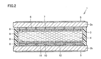
- FIG. 2 is a cross-sectional view schematically showing a typical example of a liquid crystal panel.
- FIG. 2 shows a liquid crystal panel including an active element (not shown) such as a TFT (Thin Film Transistor).
- the liquid crystal panel of the example shown in FIG. 2 includes, for example, two panel glasses (color filter side panel glass 2a and TFT side panel glass 2b) arranged to face each other.
- panel glasses (glass substrates) 2a and 2b are provided with a sealing resin body (seal material) 3 along the peripheral edge on the oppositely disposed side (inner surface side) and bonded together. Further, in a region sealed by the panel glasses 2a and 2b and the sealing resin body 3, liquid crystal is sealed and a liquid crystal layer 4 is formed.
- a polarizing plate 5 is adhered to the opposite side (outer surface side) of each panel glass 2a, 2b with an adhesive. Yes.
- an antireflection film 6, a color filter 7, a transparent conductive film 8 and an alignment film 9 are formed on the inner surface side of the color filter side panel glass 2a.
- a pixel electrode 10, a bus electrode 11, an insulating film 12, a transparent conductive film 8 and an alignment film 9 are formed on the inner surface side of the TFT side panel glass 2b.
- the film thicknesses of the antireflection film 6, the color filter 7, the transparent conductive film 8, the alignment film 9, the pixel electrode 10, the bus electrode 11 and the insulating film 12 are compared with the thicknesses of the two panel glasses 2a and 2b. Thin enough.
- the procedure for obtaining the aluminoborosilicate glass from the liquid crystal panel of the example shown in FIG. 2 will be described.
- the procedure for recovering the aluminoborosilicate glass as a raw material in the present invention is not limited to this, and the liquid crystal It is not limited to those recovered from the panel.
- the polarizing plate 5 is removed from the liquid crystal panel 1 having a structure as shown in FIG. 2, for example, taken out from a display device having a liquid crystal panel such as a liquid crystal television.
- the removal of the polarizing plate 5 utilizes a known mechanical method.
- the bonded glass substrates 2a and 2b are separated into two. Specifically, the four sides inside the sealing resin body 3 in the glass substrate are cut into a rectangular shape along the sealing resin body 3 using a cutting tool such as a diamond saw or a glass cutter. Thereafter, by applying an external force as necessary, the glass substrate having a size slightly smaller than the original size is cut and removed from the liquid crystal panel.
- the sealed liquid crystal layer 4 is opened, and the liquid crystal is exposed in a state of being attached to the glass substrate.
- the liquid crystal is removed by scraping off the exposed glass substrate using a resin squeegee.
- the aluminoborosilicate glass recovered from a liquid crystal panel or the like usually has impurities such as an organic thin film used for a color filter, a metal thin film used for a TFT (Thin Film Transistor), and an inorganic thin film.
- impurities can be removed by appropriately combining conventionally known mechanical methods such as sand blasting and rotational polishing, and conventionally known chemical methods such as etching with an acidic solution and an organic solvent. In this way, aluminoborosilicate glass is recovered from the liquid crystal panel taken out from the used liquid crystal television.
- step S2 Pulverization Step
- the aluminoborosilicate glass used as a raw material is pulverized.
- the size of the pulverized aluminoborosilicate glass is preferably in the range of 50 to 700 ⁇ m.
- the particle size is smaller than 50 ⁇ m, aluminoborosilicate glass does not remain in the core portion of the particles, and the whole becomes zeolitic.
- the particle size exceeds 700 ⁇ m, the pulverized shape becomes flat, and the application is limited.
- the particle size suitable for the application and making the surface layer A-type zeolitic material there is no problem due to the particle size in each application, and the material has high performance such as ion exchange capacity There is an advantage that can be manufactured.
- the reaction proceeds to the inside of the aluminoborosilicate glass, the concentration fluctuation is reduced, and it is possible to obtain a zeolite material having a uniform zeolite structure with little variation in structure.
- pulverization can be performed using a conventionally known shearing type crusher, hammer mill, roll mill, cutter mill, ball mill, jet mill, or the like. Further, it can be pulverized by performing a multi-stage process. After roughly crushing using a hammer mill or the like, fine crushing with a ball mill or the like enables efficient crushing. For example, a liquid crystal panel screen-sized aluminoborosilicate glass recovered from the above-mentioned liquid crystal panel is processed with a hammer mill or the like and roughly crushed to a size of 5 mm or less, and further pulverized to 1 mm or less using a ball mill, Used as a raw material for aluminoborosilicate glass.
- the pulverized aluminoborosilicate glass is melted and fired to perform the forming process.
- the pulverized aluminoborosilicate glass can be melted and fired to form an arbitrary shape such as foam glass, plate glass, or porous glass, and the aluminoborosilicate glass can be used as a support for zeolite.
- the surface area of the glass increases and the amount of zeolite produced in the glass surface layer also increases due to the molding process, so that the ion exchange capacity and adsorption capacity of zeolite can be improved. Is possible.
- an arbitrary foaming agent is added to the pulverized aluminoborosilicate glass, and the mixture is heated to 600 to 1200 ° C. and then rapidly cooled to obtain the foam glass. Is possible.
- a method for forming a plate glass it can be obtained by melting a ground aluminoborosilicate glass by heating to 600 to 1200 ° C. and forming it into a plate shape.
- the porous glass As a method for forming the porous glass, it can be obtained by baking the pulverized aluminoborosilicate glass at a temperature of 100 to 900 ° C. In particular, when a porous glass having a high porosity is produced, it can be obtained by firing the pulverized aluminoborosilicate glass at a temperature of 500 to 900 ° C.
- the molding process can be omitted.
- Step S4 the above-mentioned aluminoborosilicate glass powder and an acidic solution are mixed and subjected to an acid treatment.
- the said acid treatment process is not an essential process for the manufacturing method of the zeolite material of this invention, like the example shown in FIG. 1, performing the said acid treatment process between a shaping
- components other than SiO 2 such as Al 2 O 3 , B 2 O 3 , MgO, CaO, ZnO, SrO, BaO in the aluminoborosilicate glass are dissolved in an acidic solution and separated and removed. It becomes possible to promote the production of A-type zeolite.
- the surface layer of the aluminoborosilicate glass is formed with a region having a lower calcium content than the other regions (other than the surface layer) of the aluminoborosilicate glass.
- the surface layer of alumino borosilicate glass, SiO 2 content ratio is higher regions are formed in comparison with other regions of the aluminoborosilicate glass.
- the acidic solution for example, a solution containing an acidic substance such as hydrochloric acid or nitric acid can be used.
- the solution may contain two or more of these acidic substances.
- the treatment temperature in the acid treatment step is preferably 5 to 100 ° C, more preferably 40 to 100 ° C, and particularly preferably 60 to 80 ° C.
- the treatment temperature exceeds 100 ° C. in the acid treatment step, the acidic substance is vaporized, causing a safety problem and possibly causing corrosion of the equipment.
- the treatment temperature is less than 5 ° C. in the acid treatment step, the dissolution reaction becomes extremely slow and the efficiency becomes poor.
- the treatment time in the acid treatment step is preferably 1 hour or longer, more preferably 5 hours or longer, and particularly preferably 80 hours or longer.
- the stirring time is less than 1 hour in the acid treatment step, a sufficient reaction between the acidic solution and the aluminoborosilicate glass cannot be obtained, and the Ca component in the aluminoborosilicate glass remains as it is, and the synthesis rate of zeolite becomes low. End up.
- the concentration of the acidic solution can be appropriately selected according to the type of acid, the type of zeolite, etc., but is preferably 0.1 to 10N, more preferably 0.1 to 5N. This is because when the concentration of the acidic solution is less than 0.1 N, the reaction between the aluminoborosilicate glass and the acidic solution becomes small, and efficient zeolite synthesis cannot be performed. Moreover, when the density
- the mixing ratio (volume ratio) of the pulverized aluminoborosilicate glass and the acidic solution is preferably aluminoborosilicate glass powder / acidic solution 1 / 1000-1. If the mixing ratio (volume ratio) is smaller than 1/1000, the necessary acidic solution becomes too much, and the processing efficiency is deteriorated. If the mixing ratio (volume ratio) is greater than 1, the contact area between the aluminoborosilicate glass powder and the acidic solution will be small, and the dissolution reaction will not proceed sufficiently.
- stirring may be performed during the acid treatment.
- a conventionally known stirrer can be used.
- a magnetic stirrer, impeller stirrer, barrel stirrer, or the like can be used.
- the obtained mixture of pulverized aluminoborosilicate glass and acidic solution is filtered to separate the aluminoborosilicate glass powder from the acidic solution.
- an aluminum compound is added to adjust the SiO 2 / Al 2 O 3 molar ratio in the powder.
- aluminosilicates and SiO 2 contained in the borosilicate glass, aluminosilicate, Al 2 O 3, based on contained in borosilicate glass, SiO 2 / Al 2 O 3 considering the Al 2 O 3 contained in the aluminum compound added Regarding the molar ratio the Si / Al molar ratio is preferably 0.1 or more and 2 or less (SiO 2 / Al 2 O 3 molar ratio is 0.2 or more and 4 or less), more preferably Si / Al molar ratio is 1 or less (SiO 2 By adding an aluminum compound such that the 2 / Al 2 O 3 molar ratio is 2 or less, synthesis of A-type zeolite becomes possible.
- NaAlO 2 , Al (OH) 3 , AlCl 3 or the like can be used as an aluminum compound to be added.
- NaAlO 2 , Al (OH) 3 , and AlCl 3 the reactivity is high and the reaction can proceed efficiently.
- the form of the aluminum compound powder is preferable. Thereby, it becomes possible to uniformly mix and stir in the alkali treatment step described later.
- step S6 Alkali Treatment Step
- the aluminoborosilicate glass and the alkali solution are mixed and stirred.
- the alkali treatment step is not an essential step in the method for producing the A-type zeolite material of the present invention, but the alkali treatment step is performed between the preparation step and the synthesis step as in the example shown in FIG. Is preferred.
- a conventionally known stirrer is used.
- a magnetic stirrer, impeller stirrer, barrel stirrer, or the like can be used.
- the stirring temperature in the alkali treatment step is preferably 5 to 100 ° C.
- the stirring temperature in the alkali treatment step exceeds 100 ° C. in the alkali treatment step, the alkaline solution is vaporized, which may cause a safety problem.
- the stirring temperature in an alkali treatment process will be less than 5 degreeC, a dissolution reaction will become very slow and efficiency may worsen.
- the stirring time in the alkali treatment step is preferably 1 second to 100 hours. If the stirring time is less than 1 second in the alkali treatment step, a sufficient reaction between the alkali solution and the aluminoborosilicate glass cannot be obtained, and the aluminoborosilicate glass remains as it is, and the synthesis ratio of zeolite may be lowered. . In addition, if the stirring time exceeds 100 hours in the alkali treatment step, the progress of the reaction may become extremely slow and the efficiency may deteriorate.
- the alkali solution used in the alkali treatment step is not particularly limited, but sodium hydroxide, sodium carbonate, sodium hydrogen carbonate, potassium hydroxide, potassium carbonate, carbonate from the viewpoint of reactivity, waste liquid treatment, and ease of handling.
- a solution containing an alkaline substance such as potassium hydrogen is preferred.
- the solution may contain two or more of these alkaline substances.
- sodium hydroxide is preferably used as the alkaline solution.
- the concentration of the alkali solution used in the alkali treatment step can be appropriately selected according to the type of alkali, type of zeolite, etc., but is preferably 0 to 3N, more preferably 0.2 to 3N, and more preferably 0.5 to 1N. Is particularly preferred.
- concentration of the alkali solution is less than 0.2 N, the reaction between the aluminoborosilicate glass and the alkali solution becomes small, and there is a possibility that the glass phase remains so that efficient zeolite synthesis is lost.
- step S7 which is an essential step in the method for producing the A-type zeolitic material of the present invention, a mixture of aluminoborosilicate glass and an alkaline solution is used. Heat treatment.
- the heat treatment can be performed either batchwise or continuously.
- a mixture of aluminoborosilicate glass and an alkali solution is introduced into a pressure vessel or a reactor, preferably 75 to 150 ° C., more preferably 80 ° C. Heat to ⁇ 110 ° C.
- the Si component elutes in the alkaline solution and is added as sodium aluminate in advance to react with Al present in the solution to produce an aluminosilicate gel.
- the aluminosilicate gel is crystallized into zeolite by heating and holding.
- the aluminosilicate gel is generated immediately after the Si component is eluted from the aluminoborosilicate glass, that is, locally generated at the interface between the aluminoborosilicate glass and the alkali solution. Therefore, the aluminosilicate gel is formed so as to cover the glass surface layer. By heating and holding in this state, zeolite is produced on the aluminoborosilicate glass surface layer.
- the temperature in the synthesis step is less than 75 ° C.
- the synthesis reaction rate is extremely slow, the efficiency is deteriorated, the production of zeolite is slow, and the glass phase tends to remain.
- it exceeds 150 degreeC it is because phases other than A type zeolite, such as a hydroxy sodalite, will produce
- the synthesis pressure is the saturated vapor pressure at that temperature, and the amount of liquid and solid introduced into the reaction vessel is set so that the pressure is 1 to 10 atm, and the volume of the space in the reaction vessel is adjusted.
- the synthesis time is preferably 12 hours or more, more preferably 24 to 96 hours, and particularly preferably 48 to 96 hours. If the synthesis time is less than 24 hours, the zeolite may not be sufficiently produced. If the synthesis time is 96 hours or more, a large amount of hydroxysodalite or the like is produced, and the purity of the A-type zeolite is lowered.
- a zeolite material (A-type zeolite) can be obtained directly from the above-described raw materials. That is, by appropriately selecting the synthesis conditions, it is possible to directly obtain a high-purity zeolitic material (A-type zeolite) that does not require an expensive synthesizer and does not contain an impure phase.
- the method for producing the A-type zeolite material of the present invention is preferably produced by heating in a temperature range of 110 ° C. or less, and in this case, in a temperature range where the waste heat of the boiler can be used. Yes, it can contribute to energy saving.
- A-type zeolite in which no impure phase is mixed.
- A-type zeolite has the highest ion-exchange capacity among many zeolites.
- the zeolite obtained by the method of the present invention can be used as a high-performance water purification agent, soil improver and the like utilizing ion exchange performance because the A-type zeolite has high purity.
- Example 1 10 g of aluminoborosilicate glass pulverized to a center diameter of 20 ⁇ m was added to 250 mL of 5M HNO 3 and stirred at room temperature for 3 hours, followed by suction filtration and drying to obtain nitric acid-treated waste glass. 1.0 g of waste glass treated with nitric acid was added to 14 mL of 1.0 M NaOH, and further mixed with 1.3 g of NaAlO 2 .
- NaOH raw material special grade sodium hydroxide pellets manufactured by Kishida Chemical were used, and as the NaAlO 2 raw material, deer primary sodium aluminate manufactured by Kanto Chemical Co., Ltd. was used.
- the Si / Al molar ratio is 0.75.
- the synthesis was performed at 95 ° C. for 48 hours. After the synthesis was completed, the synthesized product was separated by suction filtration and dried to obtain a sample of the zeolitic material.
- FIG. 3 shows the result of X-ray diffraction measurement of the obtained sample and identification of the synthetic substance. As can be seen from FIG. 3, only the peak of A-type zeolite was observed, and an A-type zeolite single phase was obtained.
- FIG. 4 The SEM observation result of the obtained sample is shown in FIG. As can be seen from FIG. 4, cube-shaped particles peculiar to A-type zeolite were observed, and it was confirmed that the entire glass particles of the raw material were A-type zeolite when combined with the results of X-ray diffraction.
- NaAlO 2 sodium aluminate
- FIG. 5 shows the result of X-ray diffraction measurement of the obtained sample and identification of the synthetic substance. As can be seen from FIG. 5, a peak of only A-type zeolite was observed, and an A-type zeolite single phase was obtained.
- FIG. 6 The SEM observation result of the obtained sample is shown in FIG. As can be seen from FIG. 6, cube-shaped particles peculiar to A-type zeolite were observed on the surface of the glass particles, and when combined with the results of X-ray diffraction, it was confirmed that the surface layer was A-type zeolite.
- Example 3 10 g of aluminoborosilicate glass ground to a center diameter of 158 ⁇ m was added to 250 mL of 5M HNO 3 and stirred at room temperature for 3 hours, followed by suction filtration and drying to obtain nitric acid-treated waste glass. 1.0 g of waste glass treated with nitric acid was added to 14 mL of 1.0 M NaOH, respectively, and further mixed with 1.3 g of NaAlO 2 . At this time, the Si / Al molar ratio is 0.75. After stirring for 10 minutes, the synthesis was performed at 95 ° C. for 48 hours. After the synthesis was completed, the synthesized product was separated by suction filtration, and dried to obtain a sample of zeolitic material.
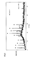
- FIG. 7 shows the result of X-ray diffraction measurement of the sample obtained by the synthesis process at 95 ° C. for 48 hours and identification of the synthetic substance.
- A-type zeolite and some hydroxy sodalite and impurity phase peaks were observed, and a mixed phase of A-type zeolite, hydroxy sodalite and an unidentified phase was obtained.
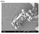
- the SEM observation result of the obtained sample is shown in FIG.
- FIG. 8 cube-shaped particles peculiar to A-type zeolite were observed on the surface of the glass particles, and when combined with the results of X-ray diffraction, it was confirmed that the glass surface layer was A-type zeolite.
- the interface between the A-type zeolite and the glass substrate is continuous, and the formation of zeolite occurs at the solid phase reaction or the solid phase liquid phase interface, the zeolite / glass interface is strong. It is a perfect combination.
- Example 4 10 g of aluminoborosilicate glass pulverized to a center diameter of 318 ⁇ m was added to 250 mL of 5M HNO 3 and stirred at room temperature for 96 to 168 hours, followed by suction filtration and drying to obtain nitric acid-treated waste glass. To 14 mL of 1.0 M NaOH, 1.0 g of waste glass with different nitric acid treatment times was added, and 1.3 g of NaAlO 2 was added to each. At this time, the Si / Al molar ratio is 0.75. After stirring for 10 minutes, the synthesis was performed at 95 ° C. for 48 hours. The synthesis conditions are shown in Table 1. After the synthesis was completed, the synthesized product was separated by suction filtration, and dried to obtain a sample of zeolitic material.
- FIG. 9 The result of X-ray diffraction measurement of the obtained sample and identification of the synthetic substance is shown in FIG.
- peaks of A-type zeolite, hydroxysodalite, and impurity phase were observed after 3 hours of acid treatment.
- a single phase of A-type zeolite was obtained at acid treatment times of 96 hours and 168 hours.
- the SEM observation result of the obtained sample is shown in FIG. As can be seen from the figure, when the acid treatment time is 96 and 168 hours, cube-shaped particles peculiar to A-type zeolite are seen, and it is confirmed that the glass surface layer is A-type zeolite when combined with the result of X-ray diffraction. did it.
- Example 5 10 g of aluminoborosilicate glass pulverized to a center diameter of 318 ⁇ m was added to 250 mL of 5M HNO 3 and stirred at room temperature for 96 hours, followed by suction filtration and drying to obtain nitric acid-treated waste glass. To 14 mL of 1.0 M NaOH, 1.0 g of waste glass treated with nitric acid was added and further mixed with 1.3 g of NaAlO 2 . At this time, the Si / Al molar ratio is 0.75. After stirring for 10 minutes, the synthesis was carried out at 95 ° C. for 48, 96, 168 and 336 hours. The synthesis conditions are shown in Table 2. After the synthesis was completed, the synthesized product was separated by suction filtration, and dried to obtain a sample of zeolitic material.
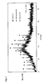
- FIG. 11 shows the result of X-ray diffraction measurement of the sample obtained by the synthesis treatment at 95 ° C. for 48, 96, 168 and 336 hours, and identification of the synthetic substance.
- a single phase of zeolite A was obtained after a synthesis time of 48 hours.
- glass remains inside the glass grains, indicating that only the glass surface is zeoliticized.
- the synthesis time was 96, 168 and 336 hours
- a mixture of zeolite A, hydroxydodalite and an unidentified phase was obtained.
- the proportion of A-type zeolite decreased and the proportion of hydroxysodalite and impurity phase increased.
- FIG. 12 (a) The SEM observation result of the obtained sample is shown in FIG.
- FIG. 12 (a) in the product obtained by the synthesis treatment at 95 ° C. for 48 hours, cube-like particles peculiar to the A-type zeolite are seen, and together with the result of X-ray diffraction, Was confirmed to be A-type zeolite.
- FIGS. 12B to 12C when the synthesis time is 96, 168 and 336 hours, cube-shaped particles and particles of other shapes are mixed.
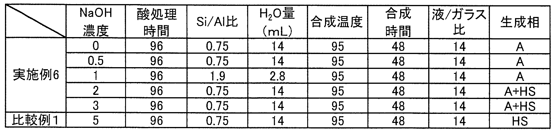
- 1.0 g of waste glass treated with nitric acid was added to each of 0.5, 1.0, 2.0, and 3.0 M NaOH aqueous solutions, and further mixed with 1.3 g of NaAlO 2 .
- the amount of NaOH aqueous solution and the Si / Al molar ratio were as shown in Table 3.
- the synthesis was performed at 95 ° C. for 48 hours. After the synthesis was completed, the synthesized product was separated by suction filtration, and dried to obtain a sample of zeolitic material.
- FIG. 14 (a) the SEM photograph of the product when it was synthesized at 95 ° C. for 48 hours in 0.5M NaOH solution is shown in FIG. 14 (a), and the product was synthesized at 95 ° C. for 48 hours in 1M NaOH solution.
- An SEM photograph of the product is shown in FIG.
- FIGS. 14A and 14B a cube shape peculiar to the A-type zeolite was generated, and it was confirmed that the glass surface was zeoliticized.
- Example 7 10 g of aluminoborosilicate glass pulverized to a center diameter of 318 ⁇ m was added to 250 mL of 5M HNO 3 and stirred at room temperature for 96 hours, followed by suction filtration and drying to obtain nitric acid-treated waste glass.
- aluminoborosilicate glass pulverized to a center diameter of 318 ⁇ m was added to 250 mL of 5M HNO 3 and stirred at room temperature for 96 hours, followed by suction filtration and drying to obtain nitric acid-treated waste glass.
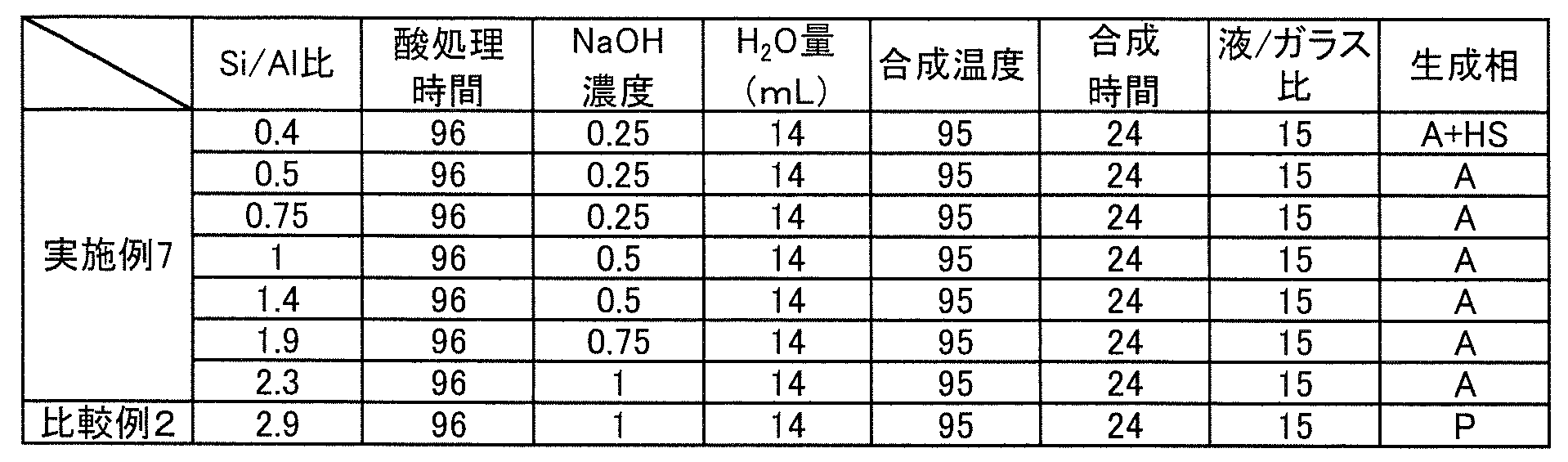
- To each 14 mL of NaOH aqueous solution 1.0 g of waste glass treated with nitric acid is added, and further mixed with a predetermined amount of NaAlO 2, and the Si / Al molar ratio is 0.4, 0.5, 0.75, 1, 1.. 4, 1.9, 2.3.
- the NaOH aqueous solution concentration was as shown in Table 4. After stirring for 10 minutes, the synthesis was performed at 95
- FIG. 15 shows the result of X-ray diffraction measurement of the obtained sample and identification of the synthetic substance.
- Si / Al molar ratio is 0.4
- the mixture of A-type zeolite and hydroxysodalite, and the Si / Al molar ratio is 0.5 to 2.3
- an A-type zeolite single phase is obtained. It was.
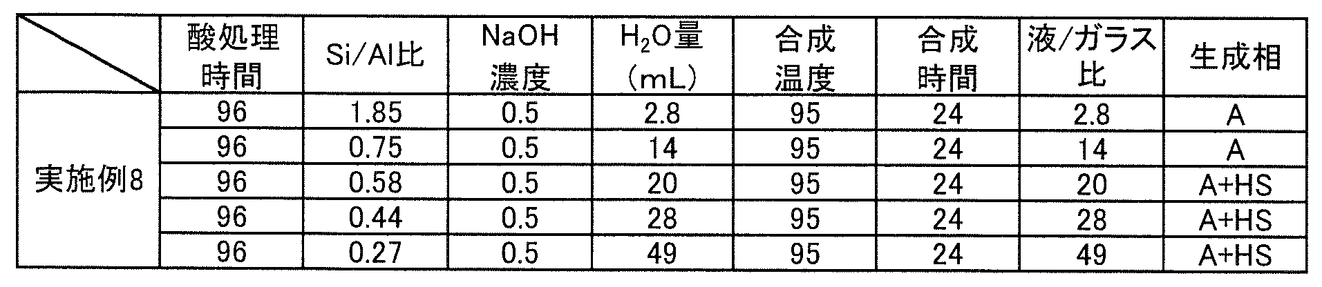
- Example 8 10 g of aluminoborosilicate glass pulverized to a center diameter of 318 ⁇ m was added to 250 mL of 5M HNO 3 and stirred at room temperature for 96 hours, followed by suction filtration and drying to obtain nitric acid-treated waste glass. To each of 2.8, 14, 20, 28, and 50 mL of 0.5 M NaOH aqueous solution, 1.0 g of waste glass treated with nitric acid was added, and the ratio of liquid (volume, mL) / glass (mass, g) was 2.8, 14 20, 28, 49.
- FIG. 16 shows the result of X-ray diffraction measurement of the obtained sample and identification of the synthetic substance.
- a type A zeolite single phase was obtained at a liquid / glass ratio of 2.8 to 14, and a mixture of type A zeolite and hydroxysodalite was obtained at 20 to 49.
- Example 9 10 g of aluminoborosilicate glass pulverized to a center diameter of 318 ⁇ m was added to 250 mL of 5M HNO 3 and stirred at room temperature for 96 hours, followed by suction filtration and drying to obtain nitric acid-treated waste glass.
- 1.0 g of waste glass treated with nitric acid was added to each of 14 mL of 1M NaOH aqueous solution, and further mixed with a predetermined amount of NaAlO 2 to make the Si / Al molar ratio 0.75.
- the NaOH aqueous solution concentration was as shown in the table.
- the synthesis was performed at 75, 95, and 150 ° C. for 48 hours.
- the synthesis conditions are shown in Table 6. After the synthesis was completed, the synthesized product was separated by suction filtration, and dried to obtain a sample of zeolitic material.
- FIG. 17 shows the result of X-ray diffraction measurement of the obtained sample and identification of the synthetic substance.
- a synthesis temperature of 75 and 95 ° C. an A-type zeolite single phase was obtained.
- a synthesis temperature of 150 ° C. a mixture of A-type zeolite and hydroxysodalite was obtained.
- aluminosilicate gel and the glass particles were further heated and maintained at 95 ° C. for 24 hours in the filtrate.
- X-ray diffraction of the product from the aluminosilicate gel and the product from the glass particles is shown in FIG.
- Type A zeolite was produced from the aluminosilicate gel.
- the glass grains remained amorphous.
- Example 11 The aluminoborosilicate glass pulverized to a center diameter of 318 ⁇ m was added to 14 mL of 1M NaOH aqueous solution and further mixed with 1.3 g of NaAlO 2 to make the Si / Al molar ratio 0.75.
- the NaOH aqueous solution concentration was as shown in Table 4. After stirring for 10 minutes, the synthesis was performed at 95 ° C. for 24 hours. After the synthesis was completed, the synthesized product was separated by suction filtration, and dried to obtain a sample of zeolitic material.
- FIG. 20 shows the result of X-ray diffraction measurement of the obtained sample and identification of the synthetic substance.
- a mixture of A-type zeolite, hydroxysodalite and an unidentified phase was obtained from the glass that had not undergone the acid treatment step, and A-type zeolite could be synthesized.
- Example 1 A nitric acid-treated waste glass was obtained in the same manner as in Example 6. 1.0 g of waste glass treated with nitric acid was added to 5.0 M NaOH aqueous solution, and further mixed with 1.3 g of NaAlO 2 . At this time, the amount of NaOH aqueous solution and the Si / Al molar ratio were as shown in Table 3. The same synthesis process as in Example 6 was performed.
- FIG. 13 shows the result of X-ray diffraction measurement of the obtained sample and identification of the synthetic substance. As can be seen from FIG. 13, a single phase of hydroxysodalite was obtained in a 5.0 M NaOH solution. A-type zeolite was not obtained.
- nitric acid-treated waste glass was obtained in the same manner as in Example 7. 1.0 g of nitric acid-treated waste glass was added to each 14 mL NaOH aqueous solution, and further mixed with a predetermined amount of NaAlO 2 to make the Si / Al molar ratio 2.9. The NaOH aqueous solution concentration was as shown in Table 4. The same synthesis process as in Example 7 was performed.
- FIG. 15 shows the result of X-ray diffraction measurement of the obtained sample and identification of the synthetic substance.
- Si / Al molar ratio was 2.9
- P-type zeolite was obtained and A-type zeolite was not produced.
- ⁇ Comparative Example 3> The aluminoborosilicate glass ground to a center diameter of 318 ⁇ m was subjected to the same heat treatment as in Example 10 without acid treatment. Specifically, 1.0 g of 14 mL of 1.0M glass just ground was added, and 1.3 g of NaAlO 2 was added to each. At this time, the Si / Al molar ratio is 0.75. After stirring for 10 minutes, it was kept at 95 ° C. for 2 hours. Then, when it filtered using the filter of a 100 micrometer mesh, as shown in FIG. 21, the aluminosilicate gel was not produced
- liquid crystal panel 1 liquid crystal panel, 2a color filter side panel glass, 2b TFT side panel glass, 3 seal resin body, 4 liquid crystal layer, 5 optical film, 6 antireflection film, 7 color filter, 8 transparent conductive film, 9 alignment film, 10 pixels Electrode, 11 bus electrode, 12 insulating film.
Landscapes
- Chemical & Material Sciences (AREA)
- Engineering & Computer Science (AREA)
- Environmental & Geological Engineering (AREA)
- Organic Chemistry (AREA)
- Chemical Kinetics & Catalysis (AREA)
- Life Sciences & Earth Sciences (AREA)
- General Life Sciences & Earth Sciences (AREA)
- Geology (AREA)
- General Health & Medical Sciences (AREA)
- Toxicology (AREA)
- General Chemical & Material Sciences (AREA)
- Inorganic Chemistry (AREA)
- Health & Medical Sciences (AREA)
- Dispersion Chemistry (AREA)
- Materials Engineering (AREA)
- Silicates, Zeolites, And Molecular Sieves (AREA)
Abstract
Description
図1に示す例では、まず、アルミノホウケイ酸ガラス回収工程(ステップS1)として、たとえば、液晶パネルからアルミノホウケイ酸ガラスを回収する。ここで、図2は、典型的な一例の液晶パネルを模式的に示す断面図である。図2には、TFT(Thin Film Transistor)などのアクティブ素子(図示せず)を備えた液晶パネルを示している。図2に示す例の液晶パネルは、たとえば、対向配置された2枚のパネルガラス(カラーフィルタ側パネルガラス2a、TFT側パネルガラス2b)を備える。これらパネルガラス(ガラス基板)2a,2bは、対向配置された側(内面側)に、周縁部に沿ってシール樹脂体(シール材)3が設けられ、互いに貼り合わされてなる。また、これらパネルガラス2a,2bとシール樹脂体3とによって密封された領域には、液晶が封入され、液晶層4が形成されている。
図1に示す例では、続く粉砕工程(ステップS2)において、原料として使用するアルミノホウケイ酸ガラスを粉砕する。ここで、アルミノホウケイ酸ガラスの粉砕のサイズとしては、50~700μmの範囲内であることが好ましい。アルミノホウケイ酸ガラスを50~700μmに粉砕したものを原料とすることで、表層でのゼオライト化反応が生じるとともに、粒のコア部分にアルミノホウケイ酸ガラスを残すことができる。粒径が50μmより小さくなると、粒のコア部分にアルミノホウケイ酸ガラスが残らずに全体がゼオライト化してしまう。一方、粒径が700μmを超えると、粉砕形状が扁平になるため、用途が限定されてしまう。また、用途に合わせた粒径とすることで、かつ、表層はA型ゼオライト化した材料とすることで、各用途での粒径サイズによる不具合が生じず、イオン交換能などの性能が高い材料が製造できるという利点がある。また、アルミノホウケイ酸ガラス内部まで反応が進行し、濃度のゆらぎが減少し、構造のばらつきが少ない、均一なゼオライト構造をもったゼオライト材料を得ることが可能となる。
図1に示す例では、続く成形加工工程(ステップS3)において、粉砕したアルミノホウケイ酸ガラスに溶融、焼成を行ない、成形加工を施す。たとえば、粉砕したアルミノホウケイ酸ガラスを溶融、焼成することにより、発泡ガラスや板ガラス、多孔質ガラスなどの任意の形状に成形し、アルミノホウケイ酸ガラスをゼオライトの支持体とすることができる。また、成形加工により、発泡ガラスや多孔質ガラスの場合では、ガラスの表面積が増大し、ガラス表層部のゼオライトの生成量も増加するため、ゼオライトがもつイオン交換能や吸着能を向上させることが可能である。
図1に示す例では、続いて、酸処理工程(ステップS4)において、上述のアルミノホウケイ酸ガラス粉体と、酸性溶液とを混合し、酸処理を施す。当該酸処理工程は、本発明のゼオライト材料の製造方法に必須の工程ではないが、図1に示す例のように、成形加工工程と調合工程との間に、当該酸処理工程を行うことが好ましい。これにより、アルミノホウケイ酸ガラス中の、例えばAl2O3、B2O3、MgO、CaO、ZnO、SrO、BaOなど、SiO2以外の成分を酸性溶液に溶解させ、分離除去することによって、A型ゼオライトの生成を促進することが可能となる。
図1に示す例では、続く調合工程(ステップS5)において、アルミニウム化合物を添加し、粉体中のSiO2/Al2O3モル比の調整を行なう。たとえば、アルミノホウケイ酸ガラス中に含まれるSiO2と、アルミノホウケイ酸ガラス中に含まれるAl2O3と、添加したアルミニウム化合物に含まれるAl2O3とを考慮したSiO2/Al2O3モル比に関し、好ましくはSi/Alモル比が0.1以上2以下(SiO2/Al2O3モル比が0.2以上4以下)、より好ましくはSi/Alモル比が1以下(SiO2/Al2O3モル比が2以下)となるようにアルミニウム化合物を添加することにより、A型ゼオライトの合成が可能となる。
図1に示す例では、次に、アルカリ処理工程(ステップS6)において、上述のアルミノホウケイ酸ガラスと、アルカリ溶液とを混合し、撹拌する。当該アルカリ処理工程は、本発明のA型ゼオライト材料の製造方法に必須の工程ではないが、図1に示す例のように、調合工程と合成工程との間に、当該アルカリ処理工程を行うことが好ましい。混合し、撹拌する具体的な方法としては、従来公知の撹拌機を用いる。たとえば、マグネチックスターラー、インペラ式撹拌機、バレル式撹拌機などを用いることができる。これにより、アルミノホウケイ酸ガラスがアルカリ溶液に溶解し、ヒドロゲルの状態となる。
図1に示す例では、次に、本発明のA型ゼオライト材料の製造方法において必須の工程である合成工程(ステップS7)において、アルミノホウケイ酸ガラスとアルカリ溶液との混合物を加熱処理する。
市販の液晶パネル用ガラスについて波長分散型蛍光エックス線分析によりガラスのSiO2およびAl2O3の組成を求めた結果、SiO2が62質量%、Al2O3が18質量%であった。
中心径20μmに粉砕したアルミノホウケイ酸ガラス10gを250mLの5M HNO3に加え室温にて3時間攪拌した後、吸引ろ過、乾燥を経て硝酸処理廃ガラスを得た。14mLの1.0M NaOHに硝酸処理した廃ガラス1.0gを加え、さらに、1.3gのNaAlO2と混合した。NaOH原料は、キシダ化学製特級水酸化ナトリウムペレットを用い、NaAlO2原料は、関東化学株式会社製鹿1級アルミン酸ナトリウムを用いた。このとき、Si/Alモル比は0.75となっている。10分間攪拌した後に95℃で48時間の条件で合成を行なった。合成の完了後、吸引ろ過により合成物をろ別し、乾燥を経てゼオライト材料の試料を得た。
中心径64μmに粉砕したアルミノホウケイ酸ガラス10gを250mLの5M HNO3に加え室温にて3時間攪拌した後、吸引ろ過、乾燥を経て硝酸処理廃ガラスを得た。14mLの1.0M NaOHにそれぞれ硝酸処理した廃ガラス1.0gを加え、さらに、1.3gのアルミン酸ナトリウム(NaAlO2、関東化学工業製鹿一級)と混合した。このとき、Si/Alモル比は0.75となっている。10分間攪拌した後に95℃で48時間の条件で合成を行なった。合成の完了後、吸引ろ過により合成物をろ別し、乾燥を経てゼオライト材料の試料を得た。
中心径158μmに粉砕したアルミノホウケイ酸ガラス10gを250mLの5M HNO3に加え室温にて3時間攪拌した後、吸引ろ過、乾燥を経て硝酸処理廃ガラスを得た。14mLの1.0M NaOHにそれぞれ硝酸処理した廃ガラス1.0gを加え、さらに、それぞれ1.3gのNaAlO2と混合した。このとき、Si/Alモル比は0.75となっている。10分間攪拌した後に95℃で48時間の条件で合成を行なった。合成の完了後、吸引ろ過により合成物をろ別し、乾燥を経てゼオライト材料の試料を得た。
中心径318μmに粉砕したアルミノホウケイ酸ガラス10gを250mLの5M HNO3に加え室温にて96、168時間攪拌した後、吸引ろ過、乾燥を経て硝酸処理廃ガラスを得た。14mLの1.0M NaOHに硝酸処理の時間が異なる廃ガラスをそれぞれ1.0gずつを加え、さらに、それぞれに1.3gのNaAlO2を加えた。このとき、Si/Alモル比は0.75となっている。10分間攪拌した後に95℃で48時間の条件で合成を行なった。合成条件を表1に示した。合成の完了後、吸引ろ過により合成物をろ別し、乾燥を経てゼオライト材料の試料を得た。

中心径318μmに粉砕したアルミノホウケイ酸ガラス10gを250mLの5M HNO3に加え室温にて96時間攪拌した後、吸引ろ過、乾燥を経て硝酸処理廃ガラスを得た。14mLの1.0M NaOHにそれぞれ硝酸処理した廃ガラス1.0gを加え、さらに、1.3gのNaAlO2と混合した。このとき、Si/Alモル比は0.75となっている。10分間攪拌した後に95℃で48、96、168、336時間の条件で合成を行なった。合成条件を表2に示した。合成の完了後、吸引ろ過により合成物をろ別し、乾燥を経てゼオライト材料の試料を得た。

中心径318μmに粉砕したアルミノホウケイ酸ガラス10gを250mLの5M HNO3に加え室温にて96時間攪拌した後、吸引ろ過、乾燥を経て硝酸処理廃ガラスを得た。0.5、1.0、2.0、3.0M NaOH水溶液それぞれに硝酸処理した廃ガラス1.0gを加え、さらに、1.3gのNaAlO2と混合した。このとき、NaOH水溶液の量、Si/Alモル比は表3のとおりとした。10分間攪拌した後に95℃で48時間の条件で合成を行なった。合成の完了後、吸引ろ過により合成物をろ別し、乾燥を経てゼオライト材料の試料を得た。
中心径318μmに粉砕したアルミノホウケイ酸ガラス10gを250mLの5M HNO3に加え室温にて96時間攪拌した後、吸引ろ過、乾燥を経て硝酸処理廃ガラスを得た。14mLのNaOH水溶液それぞれに硝酸処理した廃ガラス1.0gを加え、さらに、所定量のNaAlO2と混合し、Si/Alモル比を0.4、0.5、0.75、1、1.4、1.9、2.3とした。NaOH水溶液濃度は表4に示したとおりとした。10分間攪拌した後に95℃で24時間の条件で合成を行なった。合成の完了後、吸引ろ過により合成物をろ別し、乾燥を経てゼオライト材料の試料を得た。
中心径318μmに粉砕したアルミノホウケイ酸ガラス10gを250mLの5M HNO3に加え室温にて96時間攪拌した後、吸引ろ過、乾燥を経て硝酸処理廃ガラスを得た。2.8、14、20、28、50mLの0.5M NaOH水溶液それぞれに硝酸処理した廃ガラス1.0gを加え、液(体積、mL)/ガラス(質量、g)比を2.8、14、20、28、49とした。さらに、所定量のNaAlO2と混合し、Si/Alモル比を1.85、0.75、0.58、0.44、0.27とした。10分間攪拌した後に95℃で24時間の条件で合成を行なった。合成条件を表5に示した。合成の完了後、吸引ろ過により合成物をろ別し、乾燥を経てゼオライト材料の試料を得た。
中心径318μmに粉砕したアルミノホウケイ酸ガラス10gを250mLの5M HNO3に加え室温にて96時間攪拌した後、吸引ろ過、乾燥を経て硝酸処理廃ガラスを得た。14mLの1M NaOH水溶液それぞれに硝酸処理した廃ガラス1.0gを加え、さらに、所定量のNaAlO2と混合し、Si/Alモル比を0.75とした。NaOH水溶液濃度は表に示したとおりとした。10分間攪拌した後に75、95、150℃で48時間の条件で合成を行なった。合成条件を表6に示した。合成の完了後、吸引ろ過により合成物をろ別し、乾燥を経てゼオライト材料の試料を得た。

中心径318μmに粉砕したアルミノホウケイ酸ガラス10gを250mLの5M HNO3に加え室温にて96時間攪拌した後、吸引ろ過、乾燥を経て硝酸処理廃ガラスを得た。14mLの1.0M NaOHに硝酸したガラスを1.0g加え、さらに、それぞれに1.3gのNaAlO2を加えた。このとき、Si/Alモル比は0.75となっている。10分間攪拌した後に95℃で2時間保持した。その後、100μmのメッシュのフィルターを用いてろ過したところ、ろ液中に図18に示すような白色のアルミノシリケートゲルが生成した。メッシュ上にはガラス粒子が得られた。
中心径318μmに粉砕したアルミノホウケイ酸ガラスを14mLの1M NaOH水溶液に加え、さらに、1.3gのNaAlO2と混合し、Si/Alモル比を0.75とした。NaOH水溶液濃度は表4に示したとおりとした。10分間攪拌した後に95℃で24時間の条件で合成を行なった。合成の完了後、吸引ろ過により合成物をろ別し、乾燥を経てゼオライト材料の試料を得た。
実施例6と同様の方法にて硝酸処理廃ガラスを得た。5.0M NaOH水溶液に硝酸処理した廃ガラス1.0gを加え、さらに、1.3gのNaAlO2と混合した。このとき、NaOH水溶液の量、Si/Alモル比は表3のとおりとした。実施例6と同様の合成工程処理を行った。
実施例7と同様の方法にて硝酸処理廃ガラスを得た。14mLのNaOH水溶液それぞれに硝酸処理した廃ガラス1.0gを加え、さらに、所定量のNaAlO2と混合し、Si/Alモル比を2.9とした。NaOH水溶液濃度は表4に示したとおりとした。実施例7と同様の合成工程処理を行った。
中心径318μmに粉砕したアルミノホウケイ酸ガラスを酸処理せずにそのまま実施例10と同様の加熱処理を行った。具体的には14mLの1.0M 粉砕しただけのガラスを1.0g加え、さらに、それぞれに1.3gのNaAlO2を加えた。このとき、Si/Alモル比は0.75となっている。10分間攪拌した後に95℃で2時間保持した。その後、100μmのメッシュのフィルターを用いてろ過したところ図21に示すようにアルミノシリケートゲルは生成せず、透明な液体が得られた。
Claims (17)
- アルミノホウケイ酸ガラスを原料として、表層部をゼオライト化することによるA型ゼオライト材料の製造方法であって、
アルミノホウケイ酸ガラスとアルカリ溶液との混合物を加熱処理する合成工程を含むことを特徴とするA型ゼオライト材料の製造方法。 - 前記合成工程の前に、アルミノホウケイ酸ガラスを酸性溶液と接触させ、アルミノホウケイ酸ガラスの表層に、アルミノホウケイ酸ガラスの他の領域と比較してカルシウム含有量が少ない領域を形成させる酸処理工程をさらに含む、請求項1に記載のA型ゼオライトの製造方法。
- 前記合成工程はアルミノホウケイ酸ガラスとアルカリ溶液との混合物を水熱処理により加熱処理することを特徴とする請求項2に記載のA型ゼオライト材料の製造方法。
- 前記酸処理工程と合成工程の間にアルミノホウケイ酸ガラスをアルカリ溶液と接触させるアルカリ処理工程を含むことを特徴とする、請求項3に記載のA型ゼオライト材料の製造方法。
- 前記合成工程の前に、アルミノホウケイ酸ガラスを酸性溶液と接触させ、アルミノホウケイ酸ガラスの表層に、アルミノホウケイ酸ガラスの他の領域と比較してSiO2含有比率が高い領域を形成させる酸処理工程を含むことを特徴とする請求項1に記載のA型ゼオライト材料の製造方法。
- 前記合成工程は、アルミノホウケイ酸ガラスとアルカリ溶液との混合物を加熱処理し、アルミノシリケートゲルを生成させアルミノシリケートゲルをガラス表層へ接触した状態で加熱保持することを特徴とする請求項1に記載のA型ゼオライト材料の製造方法。
- Si/Alモル比が0.1以上2.0以下となるようにアルミニウム化合物を添加する調合工程を、前記酸処理工程と前記合成工程との間にさらに含むことを特徴とする請求項2に記載のA型ゼオライト材料の製造方法。
- Si/Alモル比が1以下となるようにアルミニウム化合物を添加する調合工程を、前記酸処理工程と前記合成工程との間にさらに含むことを特徴とする請求項4に記載のA型ゼオライト材料の製造方法。
- 前記酸処理工程は、塩酸および硝酸から選ばれた少なくとも1種を含む濃度が0.1~10Nの酸性溶液を用い、1時間以上処理する工程であることを特徴とする請求項2に記載のA型ゼオライト材料の製造方法。
- 前記酸処理工程は、塩酸および硝酸から選ばれた少なくとも1種を含む濃度が0.1~10Nの酸性溶液を用い、5時間以上処理する工程であることを特徴とする請求項4に記載のA型ゼオライト材料の製造方法。
- 前記アルミノホウケイ酸ガラスを50~700μmに粉砕したものを原料とすることを特徴とする、請求項4に記載のA型ゼオライト材料の製造方法。
- 前記合成工程は、0~3Nの濃度のアルカリ溶液を用いる工程であることを特徴とする請求項1に記載のA型ゼオライト材料の製造方法。
- 前記合成工程は、0.2~3Nの濃度のアルカリ溶液を用いる工程であることを特徴とする請求項4に記載のA型ゼオライト材料の製造方法。
- 前記合成工程は、75~150℃で、24時間以上加熱処理を行なう工程であることを特徴とする請求項1に記載のA型ゼオライト材料の製造方法。
- 前記合成工程は、80~110℃で、24時間以上加熱処理を行なう工程であることを特徴とする請求項4に記載のA型ゼオライト材料の製造方法。
- 前記アルミノホウケイ酸ガラスが、SiO2:50重量%以上、Al2O3:10~20重量%の組成を有することを特徴とする請求項4に記載のA型ゼオライト材料の製造方法。
- 前記アルミノホウケイ酸ガラスが、液晶パネルから回収したアルミノホウケイ酸ガラスであることを特徴とする請求項4に記載のA型ゼオライト材料の製造方法。
Priority Applications (3)
| Application Number | Priority Date | Filing Date | Title |
|---|---|---|---|
| JP2014520012A JP5778342B2 (ja) | 2012-06-05 | 2013-06-04 | アルミノホウケイ酸ガラスを原料とするa型ゼオライトの製造方法 |
| KR1020147005212A KR20140053244A (ko) | 2012-06-05 | 2013-06-04 | 알루미노붕규산 유리를 원료로 하는 a형 제올라이트의 제조 방법 |
| CN201380004691.6A CN104039703B (zh) | 2012-06-05 | 2013-06-04 | 以铝硼硅酸盐玻璃为原料的a型沸石的制造方法 |
Applications Claiming Priority (4)
| Application Number | Priority Date | Filing Date | Title |
|---|---|---|---|
| JP2012127980 | 2012-06-05 | ||
| JP2012-127980 | 2012-06-05 | ||
| JP2012073447 | 2012-09-13 | ||
| JPPCT/JP2012/073447 | 2012-09-13 |
Publications (1)
| Publication Number | Publication Date |
|---|---|
| WO2013183646A1 true WO2013183646A1 (ja) | 2013-12-12 |
Family
ID=49712035
Family Applications (1)
| Application Number | Title | Priority Date | Filing Date |
|---|---|---|---|
| PCT/JP2013/065493 Ceased WO2013183646A1 (ja) | 2012-06-05 | 2013-06-04 | アルミノホウケイ酸ガラスを原料とするa型ゼオライトの製造方法 |
Country Status (4)
| Country | Link |
|---|---|
| JP (1) | JP5778342B2 (ja) |
| KR (1) | KR20140053244A (ja) |
| CN (1) | CN104039703B (ja) |
| WO (1) | WO2013183646A1 (ja) |
Cited By (1)
| Publication number | Priority date | Publication date | Assignee | Title |
|---|---|---|---|---|
| CN105622079A (zh) * | 2015-12-25 | 2016-06-01 | 山东硅元新型材料有限责任公司 | 分子筛膜支撑体的制备方法 |
Families Citing this family (7)
| Publication number | Priority date | Publication date | Assignee | Title |
|---|---|---|---|---|
| KR101637934B1 (ko) * | 2015-03-30 | 2016-07-08 | 한국화학연구원 | 다공성 알루미노 실리카의 제조방법 및 이에 따라 제조되는 다공성 알루미노 실리카 |
| US10052623B2 (en) | 2015-06-29 | 2018-08-21 | Industrial Technology Research Institute | Inorganic material for removing harmful substance from wastewater and method of preparing the same, and method for wastewater treatment |
| JP7076113B2 (ja) * | 2020-01-14 | 2022-05-27 | 飯田グループホールディングス株式会社 | 蟻酸生成方法及び蟻酸生成システム |
| CN112174153B (zh) * | 2020-09-11 | 2023-06-20 | 重庆大学 | 一种利用含钛高炉渣制备a型沸石的方法 |
| CN113277519B (zh) * | 2021-06-22 | 2022-09-16 | 清华大学 | 以废玻璃为原料的二氧化硅介孔材料及其制备方法和用途 |
| CN114538460B (zh) * | 2022-04-01 | 2023-07-28 | 合肥工业大学 | 一种利用废液晶显示面板制备沸石分子筛的方法 |
| CN117602652A (zh) * | 2023-11-15 | 2024-02-27 | 中南大学 | 一种含锂玻璃废料的综合处理方法 |
Citations (2)
| Publication number | Priority date | Publication date | Assignee | Title |
|---|---|---|---|---|
| JP2011126720A (ja) * | 2009-12-15 | 2011-06-30 | Morita Kagaku Kogyo Kk | 廃液から有価物と塩酸を製造する方法 |
| JP2012041251A (ja) * | 2010-08-23 | 2012-03-01 | Nippon Kensetsu Gijutsu Kk | ゼオライトの製造方法 |
-
2013
- 2013-06-04 WO PCT/JP2013/065493 patent/WO2013183646A1/ja not_active Ceased
- 2013-06-04 KR KR1020147005212A patent/KR20140053244A/ko not_active Ceased
- 2013-06-04 CN CN201380004691.6A patent/CN104039703B/zh not_active Expired - Fee Related
- 2013-06-04 JP JP2014520012A patent/JP5778342B2/ja not_active Expired - Fee Related
Patent Citations (2)
| Publication number | Priority date | Publication date | Assignee | Title |
|---|---|---|---|---|
| JP2011126720A (ja) * | 2009-12-15 | 2011-06-30 | Morita Kagaku Kogyo Kk | 廃液から有価物と塩酸を製造する方法 |
| JP2012041251A (ja) * | 2010-08-23 | 2012-03-01 | Nippon Kensetsu Gijutsu Kk | ゼオライトの製造方法 |
Non-Patent Citations (1)
| Title |
|---|
| MASATO TSUJIGUCHI ET AL.: "Glass o Mochiita Zeolite Gosei to Hyoka", ABSTRACTS OF MEETING OF JAPAN SOCIETY OF POWDER AND POWDER METALLURGY HEISEI 24 NENDO SHUNKI TAIKAI, 22 May 2012 (2012-05-22), pages 31 * |
Cited By (1)
| Publication number | Priority date | Publication date | Assignee | Title |
|---|---|---|---|---|
| CN105622079A (zh) * | 2015-12-25 | 2016-06-01 | 山东硅元新型材料有限责任公司 | 分子筛膜支撑体的制备方法 |
Also Published As
| Publication number | Publication date |
|---|---|
| JPWO2013183646A1 (ja) | 2016-02-01 |
| CN104039703A (zh) | 2014-09-10 |
| CN104039703B (zh) | 2016-08-17 |
| JP5778342B2 (ja) | 2015-09-16 |
| KR20140053244A (ko) | 2014-05-07 |
Similar Documents
| Publication | Publication Date | Title |
|---|---|---|
| JP5778342B2 (ja) | アルミノホウケイ酸ガラスを原料とするa型ゼオライトの製造方法 | |
| Yaping et al. | Synthesis of pure zeolites from supersaturated silicon and aluminum alkali extracts from fused coal fly ash | |
| US10487005B2 (en) | Porous glass ceramic composition and method for manufacturing the same | |
| TWI585062B (zh) | 合成配方及其製造與使用方法 | |
| TW422823B (en) | Method of producing synthetic silicates and use thereof in glass production | |
| CN101254933B (zh) | 从粉煤灰中提取高纯氧化铝及硅胶的方法 | |
| CN101851063A (zh) | 利用高炉水渣和粉煤灰制备微晶玻璃的工艺 | |
| JP2012116743A (ja) | 無アルカリガラスを原料とする無機材料の製造方法 | |
| CN115260807A (zh) | 一种稀土高红外辐射涂料及其制备方法和应用 | |
| CN101698567B (zh) | 电解锰渣微晶玻璃及其制备方法 | |
| KR101441238B1 (ko) | 백운석으로부터 칼슘계 화합물을 분리하는 방법 | |
| CN110092587A (zh) | 一种利用废弃物制备微晶玻璃的方法 | |
| CN115532795B (zh) | 一种高铁赤泥同步高温固碱与材料化方法及电磁波吸收粉末功能材料 | |
| JP2013142048A (ja) | 無アルカリガラスを原料とするゼオライトの製造方法、a型ゼオライトおよびそれを用いた成形体、水浄化剤、土壌改質剤、保肥剤 | |
| US8470087B2 (en) | Production method for a lightweight construction material using asbestos waste | |
| JP2014122151A (ja) | アルミノホウケイ酸ガラスを原料とするホージャサイト型ゼオライトの製造方法 | |
| CN113233774A (zh) | 一种利用气化渣制备微晶玻璃的方法及其微晶玻璃与应用 | |
| KR20120061435A (ko) | 메카노케미스트리 기술을 이용한 폐유동상 촉매성 촉매로부터 이산화규소 및 산화알루미늄 등의 유가자원 회수방법 | |
| JP2016160139A (ja) | A型ゼオライト材料の製造方法 | |
| JPH092814A (ja) | 層状結晶性ジシリケートナトリウムの製造方法 | |
| CN115073006A (zh) | 一种电解锰渣和煤矸石微晶玻璃及其制备方法 | |
| JP2016147788A (ja) | アルミノホウケイ酸ガラスを原料とするa型ゼオライトの製造方法 | |
| KR101462768B1 (ko) | 백운석으로부터 마그네슘계 화합물을 분리하는 방법 | |
| KR20220075904A (ko) | 리튬 부산물을 이용한 제올라이트 제조방법 | |
| CN119841565B (zh) | 使用海泡石制备水化硅酸镁胶凝材料的方法 |
Legal Events
| Date | Code | Title | Description |
|---|---|---|---|
| 121 | Ep: the epo has been informed by wipo that ep was designated in this application |
Ref document number: 13800422 Country of ref document: EP Kind code of ref document: A1 |
|
| ENP | Entry into the national phase |
Ref document number: 2014520012 Country of ref document: JP Kind code of ref document: A |
|
| ENP | Entry into the national phase |
Ref document number: 20147005212 Country of ref document: KR Kind code of ref document: A |
|
| NENP | Non-entry into the national phase |
Ref country code: DE |
|
| 122 | Ep: pct application non-entry in european phase |
Ref document number: 13800422 Country of ref document: EP Kind code of ref document: A1 |