WO2013183552A1 - Dispositif d'antenne et dispositif de terminal de communication - Google Patents
Dispositif d'antenne et dispositif de terminal de communication Download PDFInfo
- Publication number
- WO2013183552A1 WO2013183552A1 PCT/JP2013/065158 JP2013065158W WO2013183552A1 WO 2013183552 A1 WO2013183552 A1 WO 2013183552A1 JP 2013065158 W JP2013065158 W JP 2013065158W WO 2013183552 A1 WO2013183552 A1 WO 2013183552A1
- Authority
- WO
- WIPO (PCT)
- Prior art keywords
- coil
- antenna
- coil antenna
- booster
- conductor
- Prior art date
Links
Images


Classifications
-
- G—PHYSICS
- G06—COMPUTING; CALCULATING OR COUNTING
- G06K—GRAPHICAL DATA READING; PRESENTATION OF DATA; RECORD CARRIERS; HANDLING RECORD CARRIERS
- G06K7/00—Methods or arrangements for sensing record carriers, e.g. for reading patterns
- G06K7/10—Methods or arrangements for sensing record carriers, e.g. for reading patterns by electromagnetic radiation, e.g. optical sensing; by corpuscular radiation
- G06K7/10009—Methods or arrangements for sensing record carriers, e.g. for reading patterns by electromagnetic radiation, e.g. optical sensing; by corpuscular radiation sensing by radiation using wavelengths larger than 0.1 mm, e.g. radio-waves or microwaves
- G06K7/10158—Methods or arrangements for sensing record carriers, e.g. for reading patterns by electromagnetic radiation, e.g. optical sensing; by corpuscular radiation sensing by radiation using wavelengths larger than 0.1 mm, e.g. radio-waves or microwaves methods and means used by the interrogation device for reliably powering the wireless record carriers using an electromagnetic interrogation field
- G06K7/10178—Methods or arrangements for sensing record carriers, e.g. for reading patterns by electromagnetic radiation, e.g. optical sensing; by corpuscular radiation sensing by radiation using wavelengths larger than 0.1 mm, e.g. radio-waves or microwaves methods and means used by the interrogation device for reliably powering the wireless record carriers using an electromagnetic interrogation field including auxiliary means for focusing, repeating or boosting the electromagnetic interrogation field
-
- G—PHYSICS
- G06—COMPUTING; CALCULATING OR COUNTING
- G06K—GRAPHICAL DATA READING; PRESENTATION OF DATA; RECORD CARRIERS; HANDLING RECORD CARRIERS
- G06K19/00—Record carriers for use with machines and with at least a part designed to carry digital markings
- G06K19/06—Record carriers for use with machines and with at least a part designed to carry digital markings characterised by the kind of the digital marking, e.g. shape, nature, code
- G06K19/067—Record carriers with conductive marks, printed circuits or semiconductor circuit elements, e.g. credit or identity cards also with resonating or responding marks without active components
- G06K19/07—Record carriers with conductive marks, printed circuits or semiconductor circuit elements, e.g. credit or identity cards also with resonating or responding marks without active components with integrated circuit chips
- G06K19/077—Constructional details, e.g. mounting of circuits in the carrier
- G06K19/07749—Constructional details, e.g. mounting of circuits in the carrier the record carrier being capable of non-contact communication, e.g. constructional details of the antenna of a non-contact smart card
- G06K19/07773—Antenna details
- G06K19/07794—Antenna details the record carrier comprising a booster or auxiliary antenna in addition to the antenna connected directly to the integrated circuit
-
- H—ELECTRICITY
- H01—ELECTRIC ELEMENTS
- H01Q—ANTENNAS, i.e. RADIO AERIALS
- H01Q1/00—Details of, or arrangements associated with, antennas
- H01Q1/12—Supports; Mounting means
- H01Q1/22—Supports; Mounting means by structural association with other equipment or articles
- H01Q1/24—Supports; Mounting means by structural association with other equipment or articles with receiving set
- H01Q1/241—Supports; Mounting means by structural association with other equipment or articles with receiving set used in mobile communications, e.g. GSM
- H01Q1/242—Supports; Mounting means by structural association with other equipment or articles with receiving set used in mobile communications, e.g. GSM specially adapted for hand-held use
- H01Q1/243—Supports; Mounting means by structural association with other equipment or articles with receiving set used in mobile communications, e.g. GSM specially adapted for hand-held use with built-in antennas
-
- H—ELECTRICITY
- H01—ELECTRIC ELEMENTS
- H01Q—ANTENNAS, i.e. RADIO AERIALS
- H01Q1/00—Details of, or arrangements associated with, antennas
- H01Q1/36—Structural form of radiating elements, e.g. cone, spiral, umbrella; Particular materials used therewith
-
- H—ELECTRICITY
- H01—ELECTRIC ELEMENTS
- H01Q—ANTENNAS, i.e. RADIO AERIALS
- H01Q7/00—Loop antennas with a substantially uniform current distribution around the loop and having a directional radiation pattern in a plane perpendicular to the plane of the loop
-
- H—ELECTRICITY
- H01—ELECTRIC ELEMENTS
- H01Q—ANTENNAS, i.e. RADIO AERIALS
- H01Q7/00—Loop antennas with a substantially uniform current distribution around the loop and having a directional radiation pattern in a plane perpendicular to the plane of the loop
- H01Q7/06—Loop antennas with a substantially uniform current distribution around the loop and having a directional radiation pattern in a plane perpendicular to the plane of the loop with core of ferromagnetic material
- H01Q7/08—Ferrite rod or like elongated core
Definitions
- the present invention relates to an antenna device, for example, an antenna device used in a non-contact communication system such as NFC (Near Field Communication) and a communication terminal device including the antenna device.
- NFC Near Field Communication
- an antenna device used in a 13.56 MHz band non-contact communication system is built in a portable terminal or the like.
- This type of antenna device requires a large coil antenna in order to obtain a good communication distance, and the coil antenna is attached to the inside of a terminal case where a relatively large space can be obtained.
- the power supply circuit (RFIC chip) for processing the RF signal and the coil antenna are connected in a direct current manner through connectors and pins.
- the direct current connection method described above has the problem that the contact resistance varies due to the roughness of the contact surface, oxidation, contact pressure, etc. There is a problem in terms of reliability.
- Patent Documents 1 and 2 an operation is performed by electromagnetically coupling a transmission / reception antenna that is made conductive by wiring on a substrate to an RFIC chip mounted on the substrate, and a resonance antenna provided inside the terminal case, for example. It has been proposed to let According to this, in addition to eliminating the above-mentioned problems, the transmitting / receiving antenna has only to be coupled to the resonant antenna, so that the size can be reduced.
- the electromagnetic coupling between the booster coil antenna and the feeding coil antenna is not necessarily sufficient due to the generation of leakage magnetic flux and the like, and degradation of communication characteristics becomes a problem.
- JP 2008-306689 A Japanese Patent No. 4325621
- An object of the present invention is to provide an antenna device and a communication terminal device that can increase the degree of coupling between a feeding coil antenna and a booster coil antenna.
- the antenna device is: A feeding coil antenna connected to the feeding circuit; A booster coil antenna comprising a wound coil conductor and arranged to be electromagnetically coupled to the feeding coil antenna;
- the feeding coil antenna is composed of a first coil antenna and a second coil antenna made of a coil conductor, and the coil conductors of the first coil antenna and the second coil antenna are connected in phase with each other,
- the first coil antenna is arranged such that a winding axis of the coil conductor is orthogonal to a winding axis of the booster coil antenna, and at least a part thereof overlaps the coil conductor of the booster coil antenna in plan view.
- the winding axis of the coil conductor is parallel to the winding axis of the booster coil antenna, and at least a part of the coil opening in a plan view is the coil of the booster coil antenna. It is arranged in the vicinity of the coil conductor so as not to overlap the conductor, It is characterized by.
- a communication terminal device is a communication terminal device including the antenna device, a housing, and a printed wiring board accommodated in the housing, wherein the feeding coil antenna is the printed circuit board.
- the booster coil antenna is attached to a wiring board, and is mounted inside or outside the cover that covers the housing, or embedded in the cover using a resin molding technique.
- the feeding coil antenna is formed by the first coil antenna and the second coil antenna, and the winding axis of the coil conductor of the first coil antenna is orthogonal to the winding axis of the booster coil antenna.
- the second coil antenna is arranged such that the winding axis of the coil conductor is parallel to the winding axis of the booster coil antenna, so that magnetic flux and leakage generated around the booster coil antenna are leaked. Bonding is improved and the degree of coupling is improved. Therefore, communication characteristics are improved.
- the degree of coupling between the feeding coil antenna and the booster coil antenna is improved, and the communication characteristics are improved.
- FIG. 1 It is a disassembled perspective view which shows the antenna apparatus which is one Example. It is a perspective view which shows the said antenna apparatus.
- FIG. 1 is explanatory drawing which shows the electromagnetic field coupling of the feeding coil antenna and booster coil antenna in the said antenna apparatus, (B), (C) is a booster coil antenna with the 1st coil antenna and the 2nd coil antenna each, respectively. It is explanatory drawing which shows electromagnetic field coupling
- FIG. 1 is a top view which shows the 1st modification regarding the arrangement
- B is a top view which shows a 2nd modification.
- A is explanatory drawing which shows the effect
- B is explanatory drawing of a comparative example.
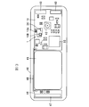
- the communication terminal apparatus which is one Example is shown, (A) is a back view of a housing cover, (B) is a top view which shows the inside of a housing main body. It is a top view which shows the inside of the housing body in the communication terminal device which is another Example.
- an antenna device 1 includes a feeding coil antenna 15 (consisting of a first coil antenna 15A and a second coil antenna 15B) on a circuit board (printed wiring board 10).
- the booster coil antenna 20 having the coil conductors 22 and 23 provided on the lower surface and the upper surface of the insulator layer 21 is formed, and the feeding coil antenna 15 is disposed close to a part of the circumference of the booster coil antenna 20. is there.
- a magnetic layer 25 may be interposed between at least part of the booster coil antenna 20 and the printed wiring board 10.
- the booster coil antenna 20 functions as a radiating element capable of transmitting and receiving high frequency signals in the HF band.
- This antenna device 1 has an equivalent circuit shown in FIG.
- the feeding coil antenna 15 (coil antennas 15A and 15B) is connected to a feeding circuit (RFIC chip 30), and includes an inductor component L1 (combined inductor component of the coil antennas 15A and 15B) and a capacitance component C1. It consists of.
- the resonance frequency is adjusted mainly by the capacitance component C1.
- the booster coil antenna 20 constitutes a series resonance circuit including inductor components L2 and L3 and line capacitance components C2 and C3 due to the coil conductors 22 and 23.
- the feeding coil antenna 15 (inductor component L1) and the booster coil antenna 20 (inductor components L2 and L3) are electromagnetically coupled to each other (indicated by a symbol M).
- the power feeding circuit is configured by the RFIC chip 30, has a memory circuit and a logic circuit, and may be configured as a bare chip IC or may be configured as a package IC.
- the coil antennas 15A and 15B are composed of magnetic cores 16A and 16B and coil conductors 17A and 17B wound around the magnetic cores 16A and 16B.
- the coil conductors 17A and 17B are connected in series or in parallel with each other through a conductor formed on the printed wiring board 10 (see FIGS. 3A and 3B).
- the first coil antenna 15A includes at least a coil and the coil conductors 22 and 23 of the booster coil antenna 20 so that the winding axis of the coil conductor 17A is orthogonal to the winding axis of the booster coil antenna 20 and in plan view. It arrange
- the winding axis of the coil conductor 17B is parallel to the winding axis of the booster coil antenna 20, and at least a part of the coil opening is a booster coil antenna 20 in plan view.
- the coil conductors 22 and 23 are arranged in the vicinity of the coil conductors 22 and 23 so as not to overlap the coil conductors 22 and 23.
- the winding axis of the coil conductor 17A is orthogonal to the winding axis of the booster coil antenna 20 in a strict sense. If they intersect within a range of 90 ° ⁇ 30 °, the degree of coupling described below can be increased.
- the winding axis of the coil conductor 17B is parallel to the winding axis of the booster coil antenna 20 to be 180 ° in a strict sense. If it is arranged in a range of 180 ° ⁇ 30 °, the degree of coupling described below can be increased.
- the magnetic cores 16A and 16B are usually made of ferrite.
- the coil conductors 17A and 17B may be formed by forming a thin film from a conductive material by a photolithography method or the like, forming a thick film using a conductive paste, or winding a conductive wire.
- the coil conductors 22 and 23 of the booster coil antenna 20 are formed by forming a thin film from a conductive material on the insulator layer 21 by a photolithography method or the like, but are not limited thereto.
- one end portions of the coil conductors 22 and 23 may be connected by an interlayer connection conductor such as a via so that the current flowing directions are the same (the other end portions are not connected).
- the said booster structure uses the capacity
- the feeding coil antenna 15 is formed by the first coil antenna 15 ⁇ / b> A and the second coil antenna 15 ⁇ / b> B, and a magnetic flux ⁇ ⁇ b> 1 generated inside the booster coil antenna 20 is generated as shown in FIG.
- the outer magnetic flux ⁇ 2 becomes a leakage magnetic flux.
- the inner magnetic flux ⁇ 1 becomes a leakage magnetic flux.
- the degree of coupling between the feeding coil antenna 15 and the booster coil antenna 20 is increased, and as a result, the communication characteristics are improved.
- the first coil antenna 15A is preferably arranged so as to overlap the coil conductors 22 and 23 of the booster coil antenna 20 in plan view.
- the second coil antenna 15B is preferably disposed in the vicinity of the inner peripheral edge or the outer peripheral edge of the coil conductors 22 and 23 of the booster coil antenna 20.
- the resonance frequency of the feeding coil antenna 15 can be adjusted by the arrangement relationship between the first coil antenna 15A and the second coil antenna 15B. That is, the total inductance value can be changed according to the arrangement relationship between the coil antennas 15A and 15B.
- the coil conductor 17B may be wound around a portion (upper part) close to the booster coil antenna 20 (first modification).
- the magnetic flux ⁇ 2 is easily removed from the second coil antenna 15B, so that unnecessary coupling with the circuit board 10 can be reduced.
- the degree of coupling by the magnetic flux ⁇ 2 between the booster coil antenna 20 and the second coil antenna 15B can be increased.
- the insulating substrate may be a flexible substrate such as polyimide, LCP, or PET film, or may be a solid substrate such as glass epoxy resin.
- the electromagnetic field coupling with the booster coil antenna 20 when the second coil antenna 15B 'is used is as described with reference to FIG. That is, as shown in FIG. 7, the magnetic flux ⁇ 1 generated inside the booster coil antenna 20 is mainly coupled to the first coil antenna 15A to form a closed loop and electromagnetically coupled, and the magnetic flux ⁇ 2 generated outside is mainly used.
- the magnetic flux ⁇ 1 generated inside the booster coil antenna 20 is mainly coupled to the first coil antenna 15A to form a closed loop and electromagnetically coupled, and the magnetic flux ⁇ 2 generated outside is mainly used.
- the second coil antenna 15B ' For the second coil antenna 15B ', the one in which the coil conductor 17B' is drawn in a planar manner on a single-layer insulating substrate by a photolithography method is shown.
- the substrate 16B ' may be a multilayer substrate, and the coil conductor 17B' may be spirally formed inside the multilayer substrate.
- the coil antenna 15B ′ in which the coil conductor 17B ′ is planarly formed on the substrate 16B ′ it is difficult to reduce the mounting area like the coil antenna 15B using the ferrite core 16B shown in FIG. However, fine processing of the coil conductor 17B 'is easy.
- the coil antennas 15A and 15B may be arranged apart from each other so as to be coupled to each of the two sides of the booster coil antenna 20.
- two first coil antennas 15A may be arranged.
- two second coil antennas 15B may be arranged.
- the arrangement number of the coil antennas 15A and 15B may be two or more.
- the feeding coil antenna 15 is configured as a single body in which magnetic cores 16 are laminated, and a coil conductor 17A is wound around one of the cores 16 to form the first coil antenna 15A, while the other The coil conductor 17B may be built into the second coil antenna 15B.
- the coil conductor 17B is formed in a coil shape by connecting the conductors formed on the laminated sheets with via-hole conductors.
- the chip component when a chip component is mounted on the feeding coil antenna 15, it is preferable that the chip component does not cover the openings of the coil antennas 15A and 15B. That is, as shown in FIG. 10, the nonmagnetic material layer 18 is laminated on the upper and lower surfaces of the magnetic core 16A of the first coil antenna 15A, and the chip component 19 is mounted on the nonmagnetic material layer 18 on the upper surface side.
- the nonmagnetic material layer 18 may be a dielectric. Further, it may be a magnetic material having a low magnetic permeability, or may be a magnetic material having a Curie temperature lower than the operating temperature.
- the magnetic layer 25 is disposed between the feeding coil antenna 15 and the booster coil antenna 20, and the operation of the magnetic layer 25 will be described with reference to FIG.
- the magnetic layer 25 ferrite can be preferably used.
- FIG. 11 shows a schematic internal configuration of the mobile terminal, and various electronic components 31 and ICs 32 are mounted on the printed wiring board 10 in addition to the feeding coil antenna 15. If the magnetic layer 25 is not disposed, the magnetic flux ⁇ 3 passing through the booster coil antenna 20 collides with the electronic component 31 and the IC 32 as shown in FIG. On the other hand, by arranging the magnetic layer 25, as shown in FIG. 11A, the magnetic flux ⁇ 3 is drawn into the magnetic layer 25, and interference with the electronic component 31 and the IC 32 is largely avoided, and communication is performed. Improved characteristics.
- the booster coil antenna 20 is attached to the back side of the housing cover 41.
- the printed wiring board 10 is accommodated in the housing body 40, and the coil antennas 15 ⁇ / b> A and 15 ⁇ / b> B and the RFIC chip 30 are mounted on the printed wiring board 10.
- a camera 42 Further mounted on the printed wiring board 10 are a camera 42, an electronic component 31, an IC 32, a UHF band antenna 43, and the like shown in FIG.
- a battery pack 45 and a printed wiring board 46 are further mounted on the housing body 40, and a UHF band antenna 47 and the like are mounted on the printed wiring board 46.
- the printed wiring boards 10 and 46 are connected by a coaxial cable 48.
- a conductor layer may be disposed on the printed wiring board 10 at least at a portion facing the inside of the coil antenna 15A and the booster coil antenna 20.
- the leakage flux from the booster coil antenna 20 is absorbed by the ground conductor, so that the influence on other components can be avoided.
- Such a conductor layer may be composed of not only a ground conductor provided on the printed wiring board 10 but also a metal foil, a liquid crystal panel, a battery pack, a shield case, and the like.
- the first coil antenna 15 ⁇ / b> A and the second coil antenna 15 ⁇ / b> B are formed directly on the printed wiring board 10. That is, the first coil antenna 15 ⁇ / b> A is formed in a spiral shape from the surface of the printed wiring board 10, and the second coil antenna 15 ⁇ / b> B is formed in a plane on the surface of the printed wiring board 10. This eliminates the need for the ferrite cores 16A and 16B.
- the antenna device and the communication terminal device according to the present invention are not limited to the above-described embodiments, and can be variously changed within the scope of the gist.
- the detailed configuration and shape of the feeding coil antenna and booster coil antenna are arbitrary.
- the present invention is not limited to the HF band NFC antenna device, but can be used for other frequency bands such as the UHF band and other communication systems.
- the present invention is useful for an antenna device and a communication terminal device, and is particularly excellent in that the degree of coupling between a feeding coil antenna and a booster coil antenna can be increased.
Landscapes
- Engineering & Computer Science (AREA)
- Physics & Mathematics (AREA)
- Computer Networks & Wireless Communication (AREA)
- Electromagnetism (AREA)
- Toxicology (AREA)
- General Physics & Mathematics (AREA)
- Theoretical Computer Science (AREA)
- Health & Medical Sciences (AREA)
- Microelectronics & Electronic Packaging (AREA)
- Computer Hardware Design (AREA)
- General Health & Medical Sciences (AREA)
- Artificial Intelligence (AREA)
- Computer Vision & Pattern Recognition (AREA)
- Details Of Aerials (AREA)
- Support Of Aerials (AREA)
Abstract
La présente invention porte sur un dispositif d'antenne qui comporte : une antenne de bobine d'alimentation (15) qui est connectée à un circuit d'alimentation ; et une antenne de bobine amplificatrice (20) qui est composée de conducteurs de bobine enroulés (22, 23) et est disposée afin d'être couplée électromagnétiquement à l'antenne de bobine d'alimentation (15). L'antenne de bobine d'alimentation (15) est composée d'une première antenne de bobine (15A) et d'une seconde antenne de bobine (15B), qui sont formées de conducteurs de bobine qui sont connectés à la même phase. La première antenne de bobine (15A) est disposée de telle sorte que l'axe de bobinage du conducteur de bobine de celle-ci est perpendiculaire à l'axe de bobinage de l'antenne de bobine amplificatrice (20) et au moins une partie de la première antenne de bobine (15A) chevauche les conducteurs de bobine de l'antenne de bobine amplificatrice dans une vue en plan. La seconde antenne de bobine (15B) est disposée près des conducteurs de bobine (22, 23) de l'antenne de bobine amplificatrice (20) de telle sorte que l'axe de bobinage du conducteur de bobine de la seconde antenne de bobine (15B) est parallèle à l'axe de bobinage de l'antenne de bobine amplificatrice (20) et au moins une partie de l'ouverture de bobine de la seconde antenne de bobine (15B) ne chevauche pas les conducteurs de bobine (22, 23) dans une vue en plan.
Priority Applications (3)
| Application Number | Priority Date | Filing Date | Title |
|---|---|---|---|
| CN201380002858.5A CN103765675B (zh) | 2012-06-04 | 2013-05-31 | 天线装置及通信终端设备 |
| JP2013558840A JP5578291B2 (ja) | 2012-06-04 | 2013-05-31 | アンテナ装置及び通信端末機器 |
| US14/192,894 US9582693B2 (en) | 2012-06-04 | 2014-02-28 | Antenna device and communication terminal device |
Applications Claiming Priority (2)
| Application Number | Priority Date | Filing Date | Title |
|---|---|---|---|
| JP2012126990 | 2012-06-04 | ||
| JP2012-126990 | 2012-06-04 |
Related Child Applications (1)
| Application Number | Title | Priority Date | Filing Date |
|---|---|---|---|
| US14/192,894 Continuation US9582693B2 (en) | 2012-06-04 | 2014-02-28 | Antenna device and communication terminal device |
Publications (1)
| Publication Number | Publication Date |
|---|---|
| WO2013183552A1 true WO2013183552A1 (fr) | 2013-12-12 |
Family
ID=49711944
Family Applications (1)
| Application Number | Title | Priority Date | Filing Date |
|---|---|---|---|
| PCT/JP2013/065158 WO2013183552A1 (fr) | 2012-06-04 | 2013-05-31 | Dispositif d'antenne et dispositif de terminal de communication |
Country Status (4)
| Country | Link |
|---|---|
| US (1) | US9582693B2 (fr) |
| JP (1) | JP5578291B2 (fr) |
| CN (1) | CN103765675B (fr) |
| WO (1) | WO2013183552A1 (fr) |
Cited By (9)
| Publication number | Priority date | Publication date | Assignee | Title |
|---|---|---|---|---|
| WO2015099026A1 (fr) * | 2013-12-27 | 2015-07-02 | トッパン・フォームズ株式会社 | Émetteur-récepteur de données sans contact et étiquette à circuit intégré (ci) sans fil et support de circuit intégré sans fil comprenant cette dernière |
| WO2016125723A1 (fr) * | 2015-02-02 | 2016-08-11 | 株式会社村田製作所 | Système d'antenne et dispositif électronique |
| CN106560954A (zh) * | 2015-10-02 | 2017-04-12 | 株式会社东芝 | 存储卡插槽装置和具备该存储卡插槽装置的电子设备 |
| JP2018019274A (ja) * | 2016-07-28 | 2018-02-01 | 大日本印刷株式会社 | 通信装置、通信システム |
| US10164347B2 (en) | 2013-12-26 | 2018-12-25 | Murata Manufacturing Co., Ltd. | Antenna device and electronic appliance |
| GB2536510B (en) * | 2013-12-26 | 2019-01-02 | Murata Manufacturing Co | Antenna device and electronic appliance |
| US10181637B2 (en) | 2014-03-28 | 2019-01-15 | Murata Manufacturing Co., Ltd. | Antenna device and communication apparatus |
| JP2019039740A (ja) * | 2017-08-24 | 2019-03-14 | シチズン時計株式会社 | 携帯型電波時計 |
| WO2020044896A1 (fr) * | 2018-08-28 | 2020-03-05 | 株式会社村田製作所 | Dispositif d'antenne et appareil électronique |
Families Citing this family (20)
| Publication number | Priority date | Publication date | Assignee | Title |
|---|---|---|---|---|
| WO2011118379A1 (fr) * | 2010-03-24 | 2011-09-29 | 株式会社村田製作所 | Système d'identification par radiofréquence |
| US9553476B2 (en) * | 2012-03-23 | 2017-01-24 | Lg Innotek Co., Ltd. | Antenna assembly and method for manufacturing same |
| US9806565B2 (en) | 2012-03-23 | 2017-10-31 | Lg Innotek Co., Ltd. | Wireless power receiver and method of manufacturing the same |
| WO2016039584A1 (fr) * | 2014-09-12 | 2016-03-17 | 주식회사 아모텍 | Module d'antenne cadre à boucles multiples et terminal mobile le comportant |
| US9912058B2 (en) * | 2014-10-21 | 2018-03-06 | Infineon Technologies Ag | Hybrid antenna, antenna arrangement and method for manufacturing an antenna arrangement |
| JP6315145B2 (ja) * | 2015-02-27 | 2018-04-25 | 株式会社村田製作所 | Rficデバイス及びrficデバイスを含む樹脂成型体の製造方法 |
| CN106329096B (zh) * | 2015-06-30 | 2020-03-31 | 比亚迪股份有限公司 | Nfc天线 |
| DE102015111038B4 (de) * | 2015-07-08 | 2021-05-06 | Infineon Technologies Ag | Eine vertikale Ferritantenne mit vorgefertigten Verbindungsbauteilen |
| KR102280037B1 (ko) * | 2015-07-29 | 2021-07-21 | 삼성전자주식회사 | 디스플레이에 구비된 내장 안테나용 급전장치 |
| US10090592B2 (en) * | 2015-10-29 | 2018-10-02 | Sonitus Technologies Inc. | Communication device |
| JP6308338B2 (ja) * | 2015-12-03 | 2018-04-11 | 株式会社村田製作所 | アンテナ装置および電子機器 |
| US10361586B2 (en) * | 2015-12-29 | 2019-07-23 | Motorola Solutions, Inc. | Method of wirelessly transferring power |
| US10622705B2 (en) * | 2017-07-07 | 2020-04-14 | Wits Co., Ltd. | Antenna module and electronic device including the same |
| US20190038214A1 (en) * | 2017-08-07 | 2019-02-07 | DePuy Synthes Products, Inc. | Sensors implantable into a patient's body, systems, and methods of using the same |
| FR3071988B1 (fr) * | 2017-10-03 | 2020-11-06 | Continental Automotive France | Dispositif de communication en champ proche |
| US10833414B2 (en) | 2018-03-02 | 2020-11-10 | Samsung Electro-Mechanics Co., Ltd. | Antenna apparatus and antenna module |
| JP6610805B1 (ja) * | 2018-03-14 | 2019-11-27 | 凸版印刷株式会社 | ループアンテナ、ループアンテナユニット、及び電子機器 |
| SK500072019A3 (sk) * | 2019-02-27 | 2020-09-03 | Logomotion Sro | Anténová sústava s dvoma solenoidovými anténami, najmä na NFC príjem a vysielanie |
| CN111313139B (zh) * | 2020-02-28 | 2020-12-01 | 江西硕天宇无线技术有限公司 | 一种无线路由器的通信天线 |
| CN115133271A (zh) * | 2022-08-11 | 2022-09-30 | 西南交通大学 | 一种并联式双环磁耦合通信抗干扰线圈天线 |
Citations (3)
| Publication number | Priority date | Publication date | Assignee | Title |
|---|---|---|---|---|
| JP2005134942A (ja) * | 2003-10-28 | 2005-05-26 | Mitsubishi Materials Corp | Rfidリーダ/ライタ及びアンテナの構造 |
| WO2008062828A1 (fr) * | 2006-11-21 | 2008-05-29 | Smart Co., Ltd. | Système d'amélioration de champ équipé d'un résonateur |
| WO2012033031A1 (fr) * | 2010-09-07 | 2012-03-15 | 株式会社村田製作所 | Appareil d'antenne et appareil de terminal de communication |
Family Cites Families (4)
| Publication number | Priority date | Publication date | Assignee | Title |
|---|---|---|---|---|
| WO2005017821A1 (fr) * | 2003-08-13 | 2005-02-24 | Murata Manufacturing Co., Ltd. | Unite de lecture/ecriture et dispositif de communication mobile |
| JP4955465B2 (ja) | 2007-06-11 | 2012-06-20 | 株式会社タムラ製作所 | ブースターアンテナ |
| GB2498109B (en) * | 2010-07-29 | 2015-01-28 | Murata Manufacturing Co | Resonant circuit and antenna device |
| JP5780298B2 (ja) * | 2011-04-18 | 2015-09-16 | 株式会社村田製作所 | アンテナ装置および通信端末装置 |
-
2013
- 2013-05-31 JP JP2013558840A patent/JP5578291B2/ja active Active
- 2013-05-31 CN CN201380002858.5A patent/CN103765675B/zh active Active
- 2013-05-31 WO PCT/JP2013/065158 patent/WO2013183552A1/fr active Application Filing
-
2014
- 2014-02-28 US US14/192,894 patent/US9582693B2/en active Active
Patent Citations (3)
| Publication number | Priority date | Publication date | Assignee | Title |
|---|---|---|---|---|
| JP2005134942A (ja) * | 2003-10-28 | 2005-05-26 | Mitsubishi Materials Corp | Rfidリーダ/ライタ及びアンテナの構造 |
| WO2008062828A1 (fr) * | 2006-11-21 | 2008-05-29 | Smart Co., Ltd. | Système d'amélioration de champ équipé d'un résonateur |
| WO2012033031A1 (fr) * | 2010-09-07 | 2012-03-15 | 株式会社村田製作所 | Appareil d'antenne et appareil de terminal de communication |
Cited By (15)
| Publication number | Priority date | Publication date | Assignee | Title |
|---|---|---|---|---|
| GB2536510B (en) * | 2013-12-26 | 2019-01-02 | Murata Manufacturing Co | Antenna device and electronic appliance |
| US10164347B2 (en) | 2013-12-26 | 2018-12-25 | Murata Manufacturing Co., Ltd. | Antenna device and electronic appliance |
| JPWO2015099026A1 (ja) * | 2013-12-27 | 2017-03-23 | トッパン・フォームズ株式会社 | 非接触型データ受送信体、並びに、それを備えた無線icタグおよび無線ic保持体 |
| WO2015099026A1 (fr) * | 2013-12-27 | 2015-07-02 | トッパン・フォームズ株式会社 | Émetteur-récepteur de données sans contact et étiquette à circuit intégré (ci) sans fil et support de circuit intégré sans fil comprenant cette dernière |
| US10181637B2 (en) | 2014-03-28 | 2019-01-15 | Murata Manufacturing Co., Ltd. | Antenna device and communication apparatus |
| WO2016125723A1 (fr) * | 2015-02-02 | 2016-08-11 | 株式会社村田製作所 | Système d'antenne et dispositif électronique |
| JPWO2016125723A1 (ja) * | 2015-02-02 | 2017-05-25 | 株式会社村田製作所 | アンテナ装置および電子機器 |
| US10629988B2 (en) | 2015-02-02 | 2020-04-21 | Murata Manufacturing Co., Ltd. | Antenna device and electronic device |
| CN106560954A (zh) * | 2015-10-02 | 2017-04-12 | 株式会社东芝 | 存储卡插槽装置和具备该存储卡插槽装置的电子设备 |
| US10063286B2 (en) | 2015-10-02 | 2018-08-28 | Toshiba Memory Corporation | Electronic device that assists wireless communication by a memory card inserted in a slot thereof |
| US10326498B2 (en) | 2015-10-02 | 2019-06-18 | Toshiba Memory Corporation | Electronic device that assists wireless communication by a memory card inserted in a slot thereof |
| JP2018019274A (ja) * | 2016-07-28 | 2018-02-01 | 大日本印刷株式会社 | 通信装置、通信システム |
| JP2019039740A (ja) * | 2017-08-24 | 2019-03-14 | シチズン時計株式会社 | 携帯型電波時計 |
| WO2020044896A1 (fr) * | 2018-08-28 | 2020-03-05 | 株式会社村田製作所 | Dispositif d'antenne et appareil électronique |
| JP6687182B1 (ja) * | 2018-08-28 | 2020-04-22 | 株式会社村田製作所 | アンテナ装置及び電子機器 |
Also Published As
| Publication number | Publication date |
|---|---|
| JPWO2013183552A1 (ja) | 2016-01-28 |
| US20140176384A1 (en) | 2014-06-26 |
| CN103765675B (zh) | 2015-06-10 |
| JP5578291B2 (ja) | 2014-08-27 |
| CN103765675A (zh) | 2014-04-30 |
| US9582693B2 (en) | 2017-02-28 |
Similar Documents
| Publication | Publication Date | Title |
|---|---|---|
| JP5578291B2 (ja) | アンテナ装置及び通信端末機器 | |
| US9997834B1 (en) | Antenna device and communication terminal apparatus | |
| JP6260729B2 (ja) | 給電素子 | |
| US9812764B2 (en) | Antenna device and wireless device | |
| JP5660254B2 (ja) | アンテナ装置及び無線通信装置 | |
| JP6327405B2 (ja) | アンテナ装置および電子機器 | |
| US9576238B2 (en) | Antenna device and communication terminal device | |
| US10374305B2 (en) | Multilayer substrate and electronic device | |
| WO2011158844A1 (fr) | Appareil terminal de communication et dispositif d'antenne | |
| US11282639B2 (en) | Antenna device and electronic apparatus | |
| US20170005391A1 (en) | Antenna device and communication apparatus | |
| JP6583599B1 (ja) | アンテナ装置、通信システム、及び電子機器 | |
| JP5884538B2 (ja) | 表面実装型アンテナ | |
| JP2009027233A (ja) | 無線icデバイス及び電子機器 |
Legal Events
| Date | Code | Title | Description |
|---|---|---|---|
| ENP | Entry into the national phase |
Ref document number: 2013558840 Country of ref document: JP Kind code of ref document: A |
|
| 121 | Ep: the epo has been informed by wipo that ep was designated in this application |
Ref document number: 13801370 Country of ref document: EP Kind code of ref document: A1 |
|
| NENP | Non-entry into the national phase |
Ref country code: DE |
|
| 122 | Ep: pct application non-entry in european phase |
Ref document number: 13801370 Country of ref document: EP Kind code of ref document: A1 |