WO2013183188A1 - 回転電機及び回転電機の製造方法 - Google Patents
回転電機及び回転電機の製造方法 Download PDFInfo
- Publication number
- WO2013183188A1 WO2013183188A1 PCT/JP2012/083161 JP2012083161W WO2013183188A1 WO 2013183188 A1 WO2013183188 A1 WO 2013183188A1 JP 2012083161 W JP2012083161 W JP 2012083161W WO 2013183188 A1 WO2013183188 A1 WO 2013183188A1
- Authority
- WO
- WIPO (PCT)
- Prior art keywords
- coil
- coating layer
- core
- rotating electrical
- electrical machine
- Prior art date
- Legal status (The legal status is an assumption and is not a legal conclusion. Google has not performed a legal analysis and makes no representation as to the accuracy of the status listed.)
- Ceased
Links
Images




Classifications
-
- H—ELECTRICITY
- H02—GENERATION; CONVERSION OR DISTRIBUTION OF ELECTRIC POWER
- H02K—DYNAMO-ELECTRIC MACHINES
- H02K1/00—Details of the magnetic circuit
- H02K1/06—Details of the magnetic circuit characterised by the shape, form or construction
- H02K1/12—Stationary parts of the magnetic circuit
- H02K1/16—Stator cores with slots for windings
-
- H—ELECTRICITY
- H02—GENERATION; CONVERSION OR DISTRIBUTION OF ELECTRIC POWER
- H02K—DYNAMO-ELECTRIC MACHINES
- H02K15/00—Processes or apparatus specially adapted for manufacturing, assembling, maintaining or repairing of dynamo-electric machines
- H02K15/02—Processes or apparatus specially adapted for manufacturing, assembling, maintaining or repairing of dynamo-electric machines of stator or rotor bodies
-
- H—ELECTRICITY
- H02—GENERATION; CONVERSION OR DISTRIBUTION OF ELECTRIC POWER
- H02K—DYNAMO-ELECTRIC MACHINES
- H02K15/00—Processes or apparatus specially adapted for manufacturing, assembling, maintaining or repairing of dynamo-electric machines
- H02K15/04—Processes or apparatus specially adapted for manufacturing, assembling, maintaining or repairing of dynamo-electric machines of windings prior to their mounting into the machines
- H02K15/043—Processes or apparatus specially adapted for manufacturing, assembling, maintaining or repairing of dynamo-electric machines of windings prior to their mounting into the machines winding flat conductive wires or sheets
- H02K15/0432—Distributed windings
-
- H—ELECTRICITY
- H02—GENERATION; CONVERSION OR DISTRIBUTION OF ELECTRIC POWER
- H02K—DYNAMO-ELECTRIC MACHINES
- H02K15/00—Processes or apparatus specially adapted for manufacturing, assembling, maintaining or repairing of dynamo-electric machines
- H02K15/06—Embedding prefabricated windings in the machines
-
- H—ELECTRICITY
- H02—GENERATION; CONVERSION OR DISTRIBUTION OF ELECTRIC POWER
- H02K—DYNAMO-ELECTRIC MACHINES
- H02K15/00—Processes or apparatus specially adapted for manufacturing, assembling, maintaining or repairing of dynamo-electric machines
- H02K15/12—Impregnating, moulding insulation, heating or drying of windings, stators, rotors or machines
-
- H—ELECTRICITY
- H02—GENERATION; CONVERSION OR DISTRIBUTION OF ELECTRIC POWER
- H02K—DYNAMO-ELECTRIC MACHINES
- H02K3/00—Details of windings
- H02K3/04—Windings characterised by the conductor shape, form or construction, e.g. with bar conductors
- H02K3/12—Windings characterised by the conductor shape, form or construction, e.g. with bar conductors arranged in slots
-
- H—ELECTRICITY
- H02—GENERATION; CONVERSION OR DISTRIBUTION OF ELECTRIC POWER
- H02K—DYNAMO-ELECTRIC MACHINES
- H02K3/00—Details of windings
- H02K3/30—Windings characterised by the insulating material
-
- H—ELECTRICITY
- H02—GENERATION; CONVERSION OR DISTRIBUTION OF ELECTRIC POWER
- H02K—DYNAMO-ELECTRIC MACHINES
- H02K3/00—Details of windings
- H02K3/44—Protection against moisture or chemical attack; Windings specially adapted for operation in liquid or gas
-
- Y—GENERAL TAGGING OF NEW TECHNOLOGICAL DEVELOPMENTS; GENERAL TAGGING OF CROSS-SECTIONAL TECHNOLOGIES SPANNING OVER SEVERAL SECTIONS OF THE IPC; TECHNICAL SUBJECTS COVERED BY FORMER USPC CROSS-REFERENCE ART COLLECTIONS [XRACs] AND DIGESTS
- Y10—TECHNICAL SUBJECTS COVERED BY FORMER USPC
- Y10T—TECHNICAL SUBJECTS COVERED BY FORMER US CLASSIFICATION
- Y10T29/00—Metal working
- Y10T29/49—Method of mechanical manufacture
- Y10T29/49002—Electrical device making
- Y10T29/49009—Dynamoelectric machine
Definitions
- the disclosed embodiment relates to a rotating electrical machine and a method for manufacturing the rotating electrical machine.
- Patent Document 1 describes a three-phase AC rotating electric machine that is provided with a stator having a Y-connected winding of each phase of distributed winding and lap winding and is driven by an inverter.
- This invention is made in view of such a problem, and it aims at providing the manufacturing method of the rotary electric machine which can aim at reduction of manufacturing time, and improvement of recyclability.
- a rotor and a stator provided so as to surround an outer peripheral side of the rotor are included, and the stator is arranged in a circumferential direction.
- a rotating electrical machine having a stator core in which a plurality of slots are arranged and a plurality of coils accommodated in the plurality of slots, wherein the stator core has a plurality of divided core elements arranged in a circumferential direction.
- Each of the plurality of coils has a circumferential one side portion accommodated in one of the plurality of slots and a circumferential other side portion of the plurality of slots.
- the air-core coil is housed in another slot different from one slot, and is constituted by an air-core coil in which the circumferential positions of the coils are sequentially shifted and overlapped, and a plurality of the air-core coils are integrally formed.
- Resin molding and coil tree Forming a structure, the coil resin structure, by assembling a plurality of divided core element, rotating electric machine that constitutes the stator core is applied.
- FIG. 2 is a transverse sectional view taken along the line II-II in FIG.
- It is a conceptual diagram showing the external appearance of a coil resin structure.
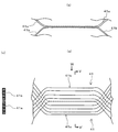
- It is a conceptual diagram showing the external appearance of a coil. It is explanatory drawing for demonstrating the overlapping winding state of a coil.
- It is a longitudinal cross-sectional view showing the whole structure of the rotary electric machine by 2nd Embodiment.
- It is a conceptual diagram showing the external appearance of a coil resin structure.
- It is a perspective view showing the whole appearance of a coil resin structure.
- It is a perspective view showing a part of external appearance of a primary molded object.
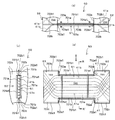
- FIG. 9 showing the details of the main part of the primary molded body, an arrow view from the direction of arrow T in FIG. 9, an arrow view from the direction of arrow S in FIG. 10 (a), and an RR in FIG. 10 (a).
- FIG. 12 is a cross-sectional view taken along the line VV ′ of FIG. 11 and FIG.
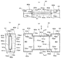
- FIG. 8 is an arrow view from the direction of the arrow U in FIG. 8, an arrow view from the direction of the arrow Q in FIG. 12A, and a PP in FIG.
- FIG. It is a cross-sectional view showing the whole structure of the rotary electric machine by 3rd Embodiment.
- the rotating electrical machine 10 of this embodiment is an embedded magnet synchronous motor including a rotor 20 inside a stator 30. That is, the rotating electrical machine 10 includes a rotor 20 that is rotatably supported, and a substantially cylindrical stator 30 that is provided so as to surround the radially outer circumferential side of the rotor 20 with a magnetic gap therebetween.
- the rotating electrical machine 10 includes a cylindrical frame 11 provided on the outer peripheral side of the stator 30, a load side bracket 12 provided on the load side (right side in FIG. 1) of the frame 11, and the load side bracket 12.
- the load side bracket 12 and the anti-load side bracket 14 are fastened to the frame 11 by bolts (not shown).
- the load side bracket 12 is provided with a dust seal 18 outside the bearing 13 in order to prevent foreign matter from entering the rotor 20.
- a connection portion 44 of the coil 41 of the stator 30 is disposed on the end face on the side opposite to the load of the stator core 32 of the stator 30.
- An external power source is connected to the connection unit 44 via a lead wire (not shown), and power is supplied to the coil 41 from the external power source via the connection unit 44.
- the rotor 20 includes a substantially annular rotor core 22 having an axial hole 21 into which the shaft 16 is fitted, and an axial permanent magnet 23 embedded in the rotor core 22 in a V shape for each pole. And have.
- the rotor 20 is configured as a field part of an embedded magnet type structure having a plurality of poles (eight poles in this example).
- the shaft 16 has a load side plate 8 that presses the load side end surface and the anti-load side end surface of the rotor 20 to prevent the rotor 20 from moving outward in the load side direction and outward in the anti-load side direction, respectively.
- An anti-load side plate 9 is attached.
- a positioning side plate 7 of the stator 20 is attached between the load side plate 8 and the load side bearing 13 in the shaft 16.
- the stator 30 includes a substantially annular stator core 32 having a plurality of (in this example, 48) slots 31, and a plurality (in this example, 48) of coils 41 accommodated in the plurality of slots 31, respectively. And having. Thereby, the stator 30 is comprised as an armature part.
- the stator core 32 is configured by arranging a plurality of (48 in this example) divided core elements 33 having a substantially sectoral cross section along the inner peripheral surface of the frame 11 over the entire circumference.
- Each divided core element 33 includes a tooth 34 having a rectangular cross-sectional shape on the radially inner side.
- the slot 31 is formed between the teeth 34, 34 provided in the adjacent divided core elements 33, 33, respectively.
- the plurality of slots 31 are provided over the entire circumference in the circumferential direction so as to follow the inner circumferential surface of the frame 11.
- the slot 31 corresponds to the teeth 34 having a rectangular cross-sectional shape, and is formed so that the cross-sectional shape becomes a fan shape that narrows radially inward.
- the plurality of (in this example, 48) coils 41 are formed in advance as one substantially cylindrical coil resin structure 45 as shown in FIG.
- the coil resin structure 45 formed by the 48 coils 41 and the detailed structure of each coil 41 will be described below with reference to FIGS.
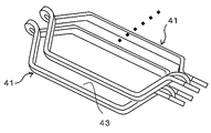
- each coil 41 is formed as a tortoiseshell type air-core coil. That is, first, the conductor 42 covered with an appropriate insulating film (not shown) is wound in a rectangular square frame shape a plurality of times (for example, four times).
- the conductor 42 is a rectangular wire having a rectangular cross section.
- the present invention is not limited to this, and a conductor having another shape (for example, a round conductor having a substantially circular cross section) may be used.
- the conductor 42 is wound while being laminated in the upper layer direction from the lowermost layer on one of the opposing long sides of the square frame, while being laminated in the lower layer direction from the uppermost layer on the other long side.
- the conductor 42 is wound while the front and back are reversed so that a loop is formed in a plane perpendicular to the plane of the square frame at the center of two opposing short sides.
- the wound body of the conductor 42 is expanded in the width direction and the length direction indicated by arrows a1, a2, a3, and a4 in FIG.
- the coil 41 which is an air core coil of the type, is obtained.
- the coil 41 is connected to the substantially straight first straight line portion 41 a (circumferential one side portion) located on the upper right side in FIG. 4 connected to the winding start end 41 s of the conductor 42 and the winding end end 41 e of the conductor 42.
- the substantially straight second linear portion 41b (circumferential other side portion) located on the lower left side in FIG. 4 and one end of the first linear portion 41a and the second linear portion 41b (upper left side in FIG. 4) are respectively connected.
- Inclined portions 41f and 41g to be connected, one turn portion 41c provided at an intermediate portion between the inclined portions 41f and 41g, and the other inclined portion connecting the other ends of the first straight portion 41a and the second straight portion 41b.
- a turn part hereinafter referred to as a nose part
- the conductor 42 is wound a plurality of times (in this example, four times).
- the conductors 42 are laminated in a plurality of layers (in this example, four layers, the same applies hereinafter) in the radial direction (vertical direction in FIG. 4) of the stator core 32.
- the first straight portion 41a and the second straight portion 41b of the coil 41 are related to when the stator core 32 is attached to the slot 31 (in other words, when the coil resin structure 45 is attached to the stator core 32).
- the stator cores 32 are arranged so as to be spaced apart from each other so as to be substantially along the circumferential direction of the stator core 32.
- the coil resin structure is provided on the radially inner side of each slot 31 (represented as “inner peripheral step” in FIG. 4).
- the first straight portion 41a (or the second straight portion 41b) of a coil 41 included in the body 45 is disposed, and radially outward of the slot 31 (referred to as “outer peripheral step” in FIG. 4)
- the first straight portion 41a (or the second straight portion 41b) of another coil included in the coil resin structure 45 is disposed.
- each of the 48 coils 41 is closer to the inside in the radial direction of the slot 31 where the first straight portion 41a is located ("inner peripheral stage” in FIG. 4).
- the second linear portion 41b is disposed on the outer side in the radial direction of another slot 31 separated by four slots in the circumferential direction ("outer circumferential stage” in FIG. 4).
- the separation distance L (see FIG. 3) between the first straight portion 41a and the second straight portion 41b of each coil 41 described above is the stator core of the coil resin structure 45 described above.
- the distance X (see FIG. 2) of the four slots 31 in the substantially circumferential direction is substantially equal (in consideration of the above-described difference between the positions in the inner and outer diameters).
- the slot 31 has a fan shape in which the cross-sectional shape narrows toward the inside in the radial direction.
- the outer shape of at least the first straight portion 41a and the second straight portion 41b of each coil 41 matches the cross-sectional shape of each slot 31 before being molded as described later. So that it is pressure molded. That is, the 41st 2nd linear part 41b arrange
- the conductor 42-1 is The dimension in the circumferential direction (left and right direction during enlargement in FIG. 4) is the smallest and the dimension in the radial direction (up and down direction in the enlarged view in FIG. 4) is large.
- the conductor 42-5 is the most.
- the circumferential dimension is small and the radial dimension is large.
- the conductor 42-6, the conductor 42-7, and the conductor 42-8 are in the order of the radially outer conductor, and the cross-sectional shape becomes flatter.
- the conductor 42-8 has the largest circumferential dimension and The radial dimension is small.
- the conductor 42-5 has a larger circumferential dimension and a smaller radial dimension than the conductor 42-4.
- each of the 48 coils 41 is formed with a gap 43 into which the teeth 34 of the stator core 32 are fitted between the two coils 41 during the mounting, And it superimposes by shifting a position, being along the circumferential direction of the stator core 32 at the time of the said mounting
- This overlapping mode is repeated so as to extend over the entire circumferential direction of the stator core 32 at the time of mounting (corresponding to the overlapping winding process).
- the 48 coils 41 which are overlapped over the entire circumference in the circumferential direction as described above, are integrally molded with a molding resin (not shown) and hardened, as shown in FIG.
- One coil resin structure 45 having a substantially cylindrical shape is formed (corresponding to a resin molding step).
- an annular stator core 32 is constructed by a plurality (48 in this example) of divided core elements 33.
- the first straight portion 41a of the coil 41 of the coil resin structure 45 is accommodated in the inner peripheral stage of each slot 31 formed between the teeth 34 of the two adjacent divided core elements 33, 33, And the coil resin structure 45 and the said stator core 32 are assembled
- each of the plurality of coils 41 is configured by an air-core coil, and the first straight portion 41a and the second straight portion 41b are separately provided in different slots 31. It is arranged in a so-called lap winding manner in which the circumferential position is sequentially shifted while being inserted.
- a plurality of coils 41 which are air-core coils that are overlapped and arranged in the circumferential direction as described above, are integrally molded in advance without being inserted into the slot 31, and one coil is formed.
- a resin structure 45 is formed.
- the stator core 32 is configured by arranging a plurality of divided core elements 33 over the entire circumference in the circumferential direction.
- Each of the plurality of core elements 33 includes teeth 34, and the slot 31 is formed between two adjacent core elements 33 when a plurality of core elements 33 are arranged.
- the plurality of divided core elements 33 are assembled from the outer peripheral side of the coil resin structure 45 while each of the plurality of coils 41 provided in the coil resin structure 45 is inserted into the corresponding two slots 31.
- the stator 30 is manufactured in which a plurality of coils 41 that are wound in layers are inserted into the plurality of slots 31 of the fixed iron core 32.
- the plurality of coils 41 are constructed as one coil resin structure 45 before being individually inserted into the plurality of slots 31 and divided into the one coil resin structure 45.
- the stator core 32 having the structure is inserted.
- the plurality of coils 41 are formed in one resin structure in the sub-line of the manufacturing process in advance.
- a body 45 can be prepared.
- the stator 30 is constituted by an assembly of the fixed core 32 having a divided structure as described above and one coil resin structure 45, so that the rotating electrical machine 10 becomes unnecessary and can be easily disassembled when discarded. it can.
- the iron material used on the iron core 32 side and the copper material used for the conductor 42 of the coil 41 can be easily separated, and the recyclability can be greatly improved.
- each coil 41 is press-molded so that its outer shape matches the cross-sectional shape of the corresponding slot 31.
- the space factor which is the actual arrangement volume of the coil 41 occupying the slot 31 that is the arrangement space of the coil 41, can be improved more reliably.
- the rotating electrical machine 10 ⁇ / b> A of the present embodiment includes a coil resin structure 60 in the stator 30.
- the coil resin structure 60 is a plurality of coils (48 in this example, similar to the above, see FIG. 8 described later) that are the same as the first embodiment.
- 41 is overlapped over the entire circumference of the stator core 32 (see also FIG. 4 and FIG. 5), and a plurality of the overlapped coils 41 are integrally molded with a molding resin and hardened. By that, it is formed.
- Each of the plurality of coils 41 is pressure-molded so that the outer shape matches the cross-sectional shape of the corresponding two slots 31.
- the load side end surface 41A of the coil 41 is formed so as to form a partial conical surface corresponding to the inner side surface 12a by the above pressure molding so as to be in close contact with the inner side surface 12a of the load side bracket 12.
- the coil resin structure 60 includes a short cylindrical load-side coil end portion 62 positioned on the load side (corresponding to one axial direction of the rotor) and an anti-load side (rotor shaft).
- the outer diameter of the intermediate portion 64 is smaller than the outer diameters of the coil end portions 62 and 63 on both sides, and the entire cylindrical resin structure 60 is cylindrical. It has a shape of a thread winding (reel) type close to.
- the load-side coil end portion 62 is a portion where a portion such as the turn portion 41c on the one end side of each coil 41 is covered and included as shown by a broken line in FIG. 8 (details will be described later).
- the anti-load side coil end portion 63 is covered with the winding start end 41s, the winding end end 41e, the nose portion 41d, etc. on the other end side of each coil 41, as indicated by broken lines in FIG. It is a part (details will be described later).
- a plurality of slot insertion portions 61 having a substantially rectangular plate shape, which are accommodated in the plurality of slots 31 of the stator core 32, are arranged in the circumferential direction.
- the slot insertion portion 61 is a portion where the first straight portion 41a and the second straight portion 41b of each coil 41 are covered and included.
- the coil resin structure 60 is formed by performing resin molding twice on the surface with a mold resin for each of the plurality of coils 41 arranged in a substantially annular shape in advance. That is, a primary coating layer 700 (see FIG. 9 and the like to be described later) that covers the outside of each coil 41 is generated by the first resin molding, and thereby the primary molded body 50 is formed. Thereafter, by the second resin molding, a secondary coating layer 800 (see FIG. 8) covering the outside of the primary coating layer 700 is generated, whereby the coil resin structure 60 is formed.
- a primary coating layer 700 see FIG. 9 and the like to be described later
- the primary molded body 50 is configured by covering the outside of each of the plurality of coils 41 arranged in a substantially annular shape with the primary coating layer 700 (see FIGS. 11 and 10). That is, as shown in FIG. 9, the primary molded body 50 includes a load side coil end portion 52 corresponding to the load side coil end portion 62 of the coil resin structure 60, and an anti-load side coil of the coil resin structure 60. It is located between the anti-load side coil end portion 53 corresponding to the end portion 63, the load side coil end portion 52 and the anti-load side coil end portion 53, and corresponds to the intermediate portion 64 of the coil resin structure 60. An intermediate portion 54.
- the plurality of coils 41 arranged in a substantially annular shape are set in a primary mold of a split mold, a mold resin is injected into the mold, and a mold resin is placed outside each coil 41.
- the primary coating layer 700 is formed (corresponding to the primary coating step).
- the load-side coil end portion 52 having a predetermined outer diameter dimension and the anti-collision are determined regardless of which position and position each coil 41 is in the internal space of the primary mold.
- the primary molding is provided with a load-side coil end portion 53, and further comprising a plurality of slot insertion portions 51 having a predetermined outer diameter dimension and having the same shape in the middle between the coil end portions 52 and 53.
- the body 50 can be obtained.
- a plurality of substantially rectangular plate-like slot insertion portions 51 respectively corresponding to the plurality of slot insertion portions 61 of the coil resin structure 60 are arranged in the circumferential direction.
- a second straight portion 41b of one coil 41 and a first straight portion 41a of another one coil 41 are overlapped in the radial direction.
- the second straight portion 41b is disposed on the radially outer side of the slot insertion portion 51 (the upper side in FIGS. 10A and 10C), and the first straight portion 41a is a slot.
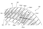
- the slot insertion portion 51 is formed in a substantially rectangular plate shape having a plurality of protrusions (described later) by covering the outer sides of the stacked first straight portion 41a and second straight portion 41b with a primary coating layer 700. It has a shape.
- the slot insertion portion 51 includes rectangular flat outer surface portions 701a and 701a and elongated rectangular flat outer surface portions 701b and 701b as outer surfaces of the primary coating layer 700.
- the outer surface portion 701a is formed on both sides of the slot insertion portion 51 along the circumferential direction (upper side and lower side in FIG. 10B, back side and front side in FIG. 10A, and FIG. 10C). Left side and right side) respectively.
- Each outer surface portion 701a is provided with at least one protrusion portion 701a1 (in this example, two) provided by projecting in the circumferential direction by a predetermined dimension from the outer surface portion 701a.
- the outer surface portion 701b is formed on both sides of the slot insertion portion 51 along the radial direction (front side and rear side in FIG. 10B, upper side and lower side in FIG. 10A, and FIG. 10C). Formed on the upper side and the lower side).
- Each outer surface portion 701b is provided with at least one protrusion portion 701b1 (in this example, one) by the primary coating layer 700 provided so as to protrude in the radial direction by a predetermined dimension from the outer surface portion 701b.
- the load-side coil end portion 52 is formed in a substantially cylindrical shape having a plurality of protrusions (described later) by covering the outer side of the turn portion 41c on one side in the axial direction of the plurality of coils 41 with the primary coating layer 700. ing.
- the load side coil end portion 52 includes a substantially disk-shaped outer surface portion 702a, an annular curved outer surface portion 702b, and an annular curved outer surface portion 702c as outer surfaces of the primary coating layer 700. .
- the outer surface portion 702a is formed on the other side in the above-described axial direction (corresponding to the above-described anti-load side. The left side in FIGS. 10B and 10A and the front side in FIG. 10C).
- the outer surface portion 702a is provided with at least one protrusion portion 702a1 (two in this example) formed by the primary coating layer 700 provided to protrude from the outer surface portion 702a by the same size as the protrusion portion 701a1.
- the outer surface portion 702b is formed on the radially outer side (the front side in FIG. 10B, the upper side in FIGS. 10A and 10C).
- the outer surface portion 702b is provided with at least one protrusion portion 702b1 (one in this example) by the primary coating layer 700 provided to protrude from the outer surface portion 702b by the same dimension as the protrusion portion 701b1.
- the outer surface portion 702c is formed on the radially inner side (the back side in FIG. 10 (b), the lower side in FIGS. 10 (a) and 10 (c)).
- the outer surface portion 702c is provided with at least one protrusion portion 702c1 (in this example, one) made of the primary coating layer 700 that protrudes from the outer surface portion 702c by the same dimension as the protrusion portion 701b1.
- the non-load side coil end portion 53 is formed in a substantially cylindrical shape having a plurality of protrusions (described later) by covering the outer side of the nose portion 41 d on the other side in the axial direction of the plurality of coils 41 with the primary coating layer 700. Has been.
- the anti-load side coil end portion 53 includes a substantially disc-shaped outer surface portion 703a, an annular curved outer surface portion 703b, and an annular curved outer surface portion 703c as outer surfaces of the primary coating layer 700. ing.
- the outer surface portion 703a is formed on one side in the above-described axial direction (corresponding to the load side, the right side in FIGS. 10B and 10A).
- the outer surface portion 703a is provided with at least one protrusion portion 703a1 (two in this example) formed by the primary coating layer 700 provided so as to protrude from the outer surface portion 703a by the same dimension as the protrusion portion 701a1.
- the outer surface portion 703b is formed on the radially outer side (the front side in FIG. 10B, the upper side in FIG. 10A).
- the outer surface portion 703b is provided with at least one protrusion portion 703b1 (in this example, one) made of the primary coating layer 700, which protrudes from the outer surface portion 703b by the same dimension as the protrusion portion 701a1 and the like.
- the outer surface portion 703c is formed on the radially inner side (the back side in FIG. 10B, the lower side in FIG. 10A).
- the outer surface portion 703c is provided with at least one protrusion portion 703c1 (in this example, one) formed by the primary coating layer 700 provided to protrude from the outer surface portion 703c by the same dimension as the protrusion portion 701a1 and the like.
- the primary molded body 50 is set in a split mold secondary molding mold, a mold resin is injected into the mold, and the primary coating layer of the primary molded body 50 is obtained.
- the coil resin structure 60 is formed by covering the outer surface portions 701a, 701b, 702a, 702b, 702c, 703a, 703b, and 703c of the 700 with the secondary coating layer 800 with a predetermined thickness. (Equivalent to secondary coating process).
- the primary molded body 50 is disposed inside the secondary mold through the above-described protrusions 701a and 701b1, protrusions 702a1, 702b1, and 702c1, protrusions 703a1, 703b1, and 703c1. Both sides in the circumferential direction and both sides in the axial direction are supported with respect to the inner wall of the secondary mold.
- the projections 701a, 701b1, 702a1, 702b1, 702c1, 703a1, 703b1, and 703c1 in the height direction are formed on the entire outer surface of the primary molded body 50 (excluding the projections).
- the secondary coating layer 800 having the same thickness as that of the dimension (corresponding to the predetermined thickness) is formed, and the coil structure 60 is completed.
- the height direction dimension of each protrusion part 701a, 701b1, 702a1, 702b1, 702c1, 703a1, 703b1, and 703c1 may mutually be the same, it may not be so.
- the coil resin structure 60 includes the intermediate portion 64, the load side coil end portion 62, and the anti-load side coil end portion 63, as described above with reference to FIG.
- the intermediate portion 64 the rectangular plate-like slot insertion portions 61 in which the outer side of the primary coating layer 700 of the slot insertion portion 51 of the primary molded body 50 is covered with the secondary coating layer 800 are arranged in the circumferential direction.
- the load side coil end part 62 is formed by covering the outer side of the primary coating layer 700 of the load side coil end part 52 of the primary molded body 50 with the secondary coating layer 800.
- the anti-load side coil end part 63 is formed by covering the outer side of the primary coating layer 700 of the anti-load side coil end part 53 of the primary molded body 50 with a secondary coating layer 800.
- the plurality of slot insertion portions 61 having a substantially rectangular plate shape are arranged in the circumferential direction.
- the slot insertion portion 61 includes rectangular outer surface portions 801a and 801a and elongated rectangular outer surface portions 801b and 801b as outer surfaces of the secondary coating layer 800 that further covers the outside of the primary coating layer 700. .
- the outer surface portion 801a is formed on both sides of the slot insertion portion 61 along the circumferential direction (upper side and lower side in FIG. 12 (b), back side and front side in FIG. 12 (a), and in FIG. 12 (c).
- the outer surface of the outer surface portion 701a by the primary coating layer 700 of the primary molded body 50 is further covered with the secondary coating layer 800 having a thickness of the height of the protrusion 701a1 by the method described above. Is formed.
- the outer surface portion 801b is formed on both sides of the slot insertion portion 61 along the radial direction (front side and rear side in FIG. 12A, upper side and lower side in FIG. 10A, and FIG. 10C).
- the outer surface of the outer surface portion 701b by the primary coating layer 700 of the primary molded body 50 is further covered with the secondary coating layer 800 having a thickness of the height of the protruding portion 701b1 by the method described above. Is formed.
- the load side coil end portion 62 includes a substantially disc-shaped outer surface portion 802a, an annular outer surface portion 802b, and an outer surface of an annular curved surface as outer surfaces of the secondary coating layer 800 further covering the outer side of the primary coating layer 700. Part 802c.
- the outer surface portion 802a is an outer surface portion formed by the primary coating layer 700 of the primary molded body 50 on the other side in the axial direction (the left side in FIGS. 12A and 12B and the front side in FIG. 12C).
- the outer surface of 702a is formed by further covering with a secondary coating layer 800 having a thickness corresponding to the height of the protrusion 702a1 by the above-described method.
- the outer surface portion 802b is an outer surface portion formed by the primary coating layer 700 of the primary molded body 50 on the radially outer side (front side in FIG. 12B, upper side in FIGS. 12A and 12C).
- the outer surface of 702b is formed by further covering with a secondary coating layer 800 having a thickness corresponding to the height of the protrusion 702b1 by the method described above.
- the outer surface portion 802c is an outer surface formed by the primary coating layer 700 of the primary molded body 50 on the radially inner side (the back side in FIG. 12B, the lower side in FIGS. 12A and 12C).
- the outer surface of the portion 702c is formed by further covering with the secondary coating layer 800 having a thickness of the height of the protrusion 702c1 by the method described above.
- the non-load-side coil end portion 63 includes an outer surface portion 803a of a substantially circular plate, an outer surface portion 803b of an annular curved surface, and an annular curved surface as outer surfaces of the secondary coating layer 800 further covering the outer side of the primary coating layer 700.
- the outer surface portion 803a is the above-described method on the outer surface of the outer surface portion 703a by the primary coating layer 700 of the primary molded body 50 on the one axial side (the right side in FIGS. 12A and 12B). Then, it is formed by further covering with a secondary coating layer 800 having a thickness corresponding to the height of the protrusion 703a1.
- the outer surface portion 803b is an outer surface portion formed by the primary coating layer 700 of the primary molded body 50 on the radially outer side (the front side in FIG. 12B, the upper side in FIGS. 12A and 12C).
- the outer surface of 702b is formed by further covering with a secondary coating layer 800 having a thickness corresponding to the height of the protrusion 702b1 by the method described above.
- the outer surface portion 803c is an outer surface by the primary covering layer 700 of the primary molded body 50 on the radially inner side (the back side in FIG. 12B, the lower side in FIGS. 12A and 12C).
- the outer surface of the portion 703c is formed by further covering with a secondary coating layer 800 having a thickness of the height of the protruding portion 703c1 by the method described above.
- the same effect as in the first embodiment can be obtained. That is, by constructing the coil resin structure 45 with a high space factor by a plurality of coils 41 in a sub-line that is a separate line from the main line, the heat generation of the coil 41 itself is reduced and the cooling performance of the rotating electrical machine 10 is improved. Can be improved. Moreover, the molding resin molding work in the main line is unnecessary, and the manufacturing time can be greatly reduced. Furthermore, when the rotating electrical machine 10 becomes unnecessary and is discarded, it can be easily disassembled. In particular, for example, the iron material used on the stator core 35 side and the copper material used for the conductor 42 of the coil 41 can be easily separated, and recyclability can be greatly improved.
- the following effects are obtained in addition to the above. That is, in this embodiment, after the primary coating layer 700 is formed on the outside of the coil 41 that is an air-core coil, the secondary coating layer 800 is further formed on the outside thereof, whereby the coil resin structure 60 is manufactured. Is done. In the primary coating step, the coil 41 is placed in the primary molding die, resin is injected into the mold, and the coil 41 is covered with the primary coating layer 700. In that case, the external shape dimension (in other words, the shape dimension of the space formed inside the said shaping
- the external shape dimension in other words, the shape dimension of the space formed inside the said shaping
- the primary molded body 50 is put into another secondary molding die, a resin is injected into the mold, and the primary molded body 50 is covered with the secondary coating layer 800.
- the outer shape dimension of the primary molded body 50 is managed with high accuracy by the primary molding die (the outer shape dimension of the primary molded body 50 is irrespective of the position of each coil 41 inside the primary molded body 50. Therefore, the secondary coating layer 800 can be formed on the outside of the primary molded body 51 with a uniform thickness.
- the secondary coating layer 800 is uniformly formed on the outside of the primary molded body 50 whose outer shape dimensions are managed with high accuracy by the primary coating layer 700. Thereby, in the resin coating layer (primary coating layer 700 + secondary coating layer 800) formed on the outer peripheral side of the coil 41, a minimum necessary thickness can be ensured.
- the winding (conductor 42) is wound at the time of manufacturing the coil 41 (or when it is press-molded thereafter), which is a stage before the formation of the primary coating layer 700, for example, the winding is lifted.
- the outer shape protrudes to the outside or is distorted due to the occurrence or the like and does not necessarily have a desired outer dimension with high accuracy (hereinafter, referred to as “indefinite shape” as appropriate).
- the above-described high-precision primary molding is forcibly performed by storing the irregularly shaped coil 41 inside the primary molding die and closing the primary molding die.
- the outer shape dimensions of the body 50 can be realized.
- the portion of the coil 41 that is contacted and pressed by the primary mold does not flow in the resin, and the thickness of the primary coating layer 700 is 0 (or a value close thereto).
- the secondary coating layer 800 having a predetermined thickness is then uniformly formed over the entire outer region of the primary coating layer 700, the resin coating layer can be reliably formed also for the portion.
- the outer surface of the slot insertion portion 51 (outer surface portion 701a and outer surface portion 701b), the outer surface of the load side coil end portion 52 (outer surface portion 702a, outer surface portion 702b, and outer surface portion).
- 702c) a plurality of protrusions (protrusions 701a1, 701b1, protrusions) projecting from the outer surfaces by a predetermined dimension with respect to the outer surface (outer surface 703a, outer surface 703b, and outer surface 703c) of the anti-load side coil end portion 53 Parts 702a1, 702b1, 702c1, and projections 703a1, 703b1, 703c1).
- the secondary coating layer 800 is provided so as to cover the outside of the primary coating layer 700 with a thickness equal to the predetermined dimension (height direction dimension of each protrusion).
- the primary molded body 50 after the primary coating layer 700 is formed has the projections 701a1, 701b1, 702a1, which have predetermined dimensions (equal to the thickness dimension of the secondary coating layer 800).
- 702b1, 702c1, 703a1, 703b1, and 703c1 are provided on each outer surface portion.
- the protrusions 701a1, 701b1, 702a1 the inner wall of the secondary molding die.
- the entire primary molded body 50 can be reliably supported by 702b1, 702c1, 703a1, 703b1, and 703c1.
- the resin is injected and filled around the primary molded body 50 in a state of being supported by the protrusions 701a1, 701b1, 702a1, 702b1, 702c1, 703a1, 703b1, and 703c1.
- the covering layer 800 covers the outside of the primary covering layer 700 excluding the plurality of protrusions with a thickness equal to the predetermined dimension. Accordingly, the secondary coating layer 800 can be uniformly and reliably provided on the periphery of the primary molded body 50 accommodated in the secondary mold, except for the protrusions 701a1, 701b1, 702a1, 702b1, 702c1, 703a1, 703b1, and 703c1. Can be formed.
- the coil resin structure 60 is configured such that the outer diameter of the intermediate portion 64 including the slot insertion portions 61 accommodated in the plurality of slots 31 has coil ends on both sides along the axial direction of the rotor 30. It is smaller than the outer diameter of the parts 62 and 63. This has the following significance.
- the outer diameter of the intermediate portion 64 in which separate members / structures are arranged on the inside and outside in the radial direction as described above is used as the coil end portion without such an arrangement. It is made smaller than the outer diameter of 62,63. As a result, the entire rotating electrical machine 10A can be prevented from being enlarged in the radial direction, and downsizing can be achieved.
- the rotating electrical machine 10 ⁇ / b> B of the present embodiment is a reluctance motor including a rotor 20 inside a stator 30. Parts equivalent to those in the first embodiment are denoted by the same reference numerals, and description thereof is omitted or simplified as appropriate.
- the stator 30 includes a stator core 35.
- a plurality (72 in this example) of divided core elements 36 are arranged along the inner peripheral surface of the frame 11 of the stator 30 (see FIG. 2). Is arranged over.
- Each divided core element 36 includes a tooth 37 having a tapered trapezoidal cross section on the radially inner side.
- a slot 38 having a rectangular cross section (rectangular shape) is formed between the teeth 37 of the divided core elements 36 adjacent to each other.
- a plurality (72 in this example) of coils 41 are inserted (accommodated) in a plurality (72 in this example) of the slots 38.
- the coils 41 are wound in an overlapping manner so that a gap 43 into which the teeth 37 of the split core element 36 are fitted is formed between the two coils 41, 41.
- the 72 wound coils 41 are integrally molded with a mold resin (not shown) to form one substantially cylindrical coil resin structure 45 (not shown; see also FIG. 8 above). .
- the cross-sectional shape of the teeth 37 is tapered so that the cross-sectional shape of the slot 38 remains rectangular (rectangular).
- the first linear portion 41a and the second linear portion 41b of the coil 41 are not pressed with respect to the outer shape as in the first embodiment.
- the teeth 37 of the split core element 36 are formed in the gaps 43 between the adjacent coils 41 and 41 of the coil resin structure 45 from the outer peripheral side of the coil resin structure 45. Is fitted (over the entire circumference of the coil resin structure 45). Thereby, an annular stator core 35 is constructed by 72 divided core elements 36.
- the first linear portion of the coil 41 of the coil resin structure 45 is accommodated in the inner peripheral stage of each slot 38 formed between the teeth 37 of the two adjacent split core elements 36, 36, and The coil resin structure 45 and the stator core 35 are assembled while the second straight portion of the other coil 41 of the coil resin structure 45 is accommodated in the outer peripheral stage of each slot 38.
- each layer of the conductor 42 of 4 layers is equipped with the same substantially rectangular cross-sectional shape.
- the second straight portion of the present embodiment corresponds to the second straight portion 41b of the second embodiment, but each layer of the four-layer conductor 42 has the same substantially rectangular cross-sectional shape. . In this way, the stator 30 is assembled.
- the rotor core 22 of the rotor 20 is provided with a total of 24 gap portions 25, each having three poles in a plurality of poles (eight poles in this example) along the circumferential direction.
- the gap 25 is convexly curved inward in the radial direction. Since the gap 25 can make a difference in the magnetic path resistance of the rotor core, reluctance torque is generated.
- the same effects as those of the first embodiment can be obtained. That is, by constructing the coil resin structure 45 with a high space factor by a plurality of coils 41 in a sub-line that is a separate line from the main line, the heat generation of the coil 41 itself is reduced and the cooling performance of the rotating electrical machine 10 is improved. Can be improved. Moreover, the molding resin molding work in the main line is unnecessary, and the manufacturing time can be greatly reduced. Furthermore, when the rotating electrical machine 10 becomes unnecessary and is discarded, it can be easily disassembled. In particular, for example, the iron material used on the stator core 35 side and the copper material used for the conductor 42 of the coil 41 can be easily separated, and recyclability can be greatly improved.
Landscapes
- Engineering & Computer Science (AREA)
- Power Engineering (AREA)
- Manufacturing & Machinery (AREA)
- Manufacture Of Motors, Generators (AREA)
- Insulation, Fastening Of Motor, Generator Windings (AREA)
- Iron Core Of Rotating Electric Machines (AREA)
Description
開示の実施形態は、回転電機及び回転電機の製造方法に関する。
特許文献1には、分布巻きかつ重ね巻の各相の巻線をY結線としたステータを備え、インバータによって駆動される三相交流回転電機が記載されている。
上記従来技術の回転電機は、製造工程において、複数のコイルを固定子鉄心の複数のスロットに順次挿入した後、モールド樹脂で成形する必要がある。通常、モールド成形は比較的長時間を要する処理であることから、製造時間の低減が困難である。さらに、回転電機が不要となり廃棄される際、上記のようにして固定子鉄心のスロットにコイルが樹脂モールドされた構造であると、分解して材料を資源として回収する際に特に鉄材と銅材の分離が困難であり、リサイクル性が悪かった。
本発明はこのような問題点に鑑みてなされたものであり、製造時間の低減、及びリサイクル性の向上を図れる回転電機及び回転電機の製造方法を提供することを目的とする。
上記課題を解決するため、本発明の一の観点によれば、回転子と、前記回転子の外周側を囲むように設けられた固定子と、を有し、前記固定子は、周方向に複数のスロットが配列された固定子鉄心と、前記複数のスロットに収容される複数のコイルと、を有する回転電機であって、前記固定子鉄心は、分割コア要素を周方向に複数個配列して構成されており、前記複数のコイルのそれぞれは、周方向一方側部分が前記複数個のスロットのうちの1つのスロットに収容されかつ周方向他方側部分が前記複数個のスロットのうち前記1つのスロットとは異なる他のスロットに収容されて、各コイルの周方向位置が順次ずらされて重ね巻きされた空芯コイルにより構成されており、かつ、複数の前記空芯コイルを、一体的に樹脂成形し、コイル樹脂構造体を形成し、前記コイル樹脂構造体に、前記複数の分割コア要素を組み付けることにより、前記固定子鉄心を構成した回転電機が適用される。
本発明によれば、回転電機の製造時間の低減、及びリサイクル性の向上を図ることができる。
以下、本発明の実施の形態について図を参照して説明する。
(第1実施形態)
<回転電機の概略構成>
図1及び図2を用いて、第1実施形態の回転電機の構成について説明する。
<回転電機の概略構成>
図1及び図2を用いて、第1実施形態の回転電機の構成について説明する。
図1及び図2に示すように、本実施形態の回転電機10は、固定子30の内側に回転子20を備えた埋込磁石同期モータである。すなわち、回転電機10は、回転自在に支持された回転子20と、回転子20の径方向外周側を、磁気的空隙を空けて囲むように設けられた略円筒状の固定子30と、を有する。また、回転電機10は、固定子30の外周側に設けられた円筒状のフレーム11と、フレーム11の負荷側(図1中右側)に設けられた負荷側ブラケット12と、負荷側ブラケット12に外輪が嵌合された負荷側軸受13と、フレーム11の反負荷側(図1中左側)に設けられた反負荷側ブラケット14と、反負荷側ブラケット14に外輪が嵌合された反負荷側軸受15と、負荷側軸受14及び反負荷側軸受15により回転自在に支持されたシャフト16(回転軸)と、シャフト16の反負荷側(図1中左側)端部に設けられ、回転子20の回転位置を検出するエンコーダ17と、を有する。
負荷側ブラケット12及び反負荷側ブラケット14は、図示しないボルトによりフレーム11に締結されている。負荷側ブラケット12には、回転子20の内部への異物の侵入を防ぐために、軸受13の外側にダストシール18が設けられている。固定子30の固定子鉄心32の反負荷側端面には、固定子30のコイル41の結線部44が配置されている。結線部44には、図示しないリード線を介し外部電源が接続されており、当該外部電源から結線部44を介してコイル41への給電が行われる。
回転子20は、シャフト16を嵌合する軸方向の穴部21を有する略円環状の回転子鉄心22と、回転子鉄心22に1極毎にV字状に埋設した軸方向の永久磁石23と、を有している。これにより、回転子20は、複数極(本例では8極)の埋込磁石型構造の界磁部として構成されている。シャフト16には、回転子20の負荷側端面及び反負荷側端面をそれぞれ押えて、回転子20の負荷側方向外方及び反負荷側方向外方への移動をそれぞれ防止する負荷側側板8及び反負荷側側板9が取り付けられている。シャフト16における負荷側側板8と上記負荷側軸受13との間には、固定子20の位置決め用側板7が取り付けられている。
<固定子の詳細構造>
固定子30は、複数(この例では48個)のスロット31を有する略円環状の上記固定子鉄心32と、上記複数のスロット31にそれぞれ収容された複数(この例では48個)のコイル41と、を有する。これにより、固定子30は、電機子部として構成されている。固定子鉄心32は、フレーム11の内周面に沿って、横断面略扇状の複数(この例では48個)の分割コア要素33が全周にわたって配列されることによって、構成されている。各分割コア要素33は、径方向内側に、横断面形状が矩形状となるティース34を備えている。このとき、隣り合う分割コア要素33,33にそれぞれ備えられたティース34,34の間にスロット31が形成される。これにより、複数のスロット31は、上記フレーム11の内周面に沿うように、周方向全周にわたって設けられる。スロット31は、横断面形状が矩形状のティース34に対応し、横断面形状が径方向内側に向けて狭まる扇状となるように形成されている。
固定子30は、複数(この例では48個)のスロット31を有する略円環状の上記固定子鉄心32と、上記複数のスロット31にそれぞれ収容された複数(この例では48個)のコイル41と、を有する。これにより、固定子30は、電機子部として構成されている。固定子鉄心32は、フレーム11の内周面に沿って、横断面略扇状の複数(この例では48個)の分割コア要素33が全周にわたって配列されることによって、構成されている。各分割コア要素33は、径方向内側に、横断面形状が矩形状となるティース34を備えている。このとき、隣り合う分割コア要素33,33にそれぞれ備えられたティース34,34の間にスロット31が形成される。これにより、複数のスロット31は、上記フレーム11の内周面に沿うように、周方向全周にわたって設けられる。スロット31は、横断面形状が矩形状のティース34に対応し、横断面形状が径方向内側に向けて狭まる扇状となるように形成されている。
このとき、上記複数(この例では48個)のコイル41は、予め、図3に示すように、略円筒状の1つのコイル樹脂構造体45として形成されている。この48個のコイル41により形成されるコイル樹脂構造体45及び各コイル41の詳細構造について、以下、図4及び図5を用いて説明する。
<コイル41の詳細構造>
各コイル41は、図4に示すように、亀甲型の空芯コイルとして形成されている。すなわち、まず、適宜の絶縁皮膜(図示省略)で被覆された導体42が、長方形の四角枠状に複数回(例えば4回)巻回される。なお、導体42としては、この例では、横断面形状が矩形状の平角線が使用されている。しかしながらこれに限られず、その他の形状の導線(例えば横断面形状が略円形の丸導線)を用いてもよい。このとき、導体42は、四角枠の相対する長辺の一方で最下層から上層方向に積層されつつ、長辺の他方で最上層から下層方向に積層されるようにしつつ、巻回される。その際さらに、導体42は、相対する2つの短辺の中央部にて、上記四角枠の面と直交する面内でループを作るように表裏を反転しつつ、巻回される。上記巻回の後、当該導体42の巻回体が、図4中の矢印a1,a2,a3,a4で示す幅方向及び長さ方向に押し広げられて亀甲型に塑性変形することで、亀甲型の空芯コイルである上記コイル41が得られる。
各コイル41は、図4に示すように、亀甲型の空芯コイルとして形成されている。すなわち、まず、適宜の絶縁皮膜(図示省略)で被覆された導体42が、長方形の四角枠状に複数回(例えば4回)巻回される。なお、導体42としては、この例では、横断面形状が矩形状の平角線が使用されている。しかしながらこれに限られず、その他の形状の導線(例えば横断面形状が略円形の丸導線)を用いてもよい。このとき、導体42は、四角枠の相対する長辺の一方で最下層から上層方向に積層されつつ、長辺の他方で最上層から下層方向に積層されるようにしつつ、巻回される。その際さらに、導体42は、相対する2つの短辺の中央部にて、上記四角枠の面と直交する面内でループを作るように表裏を反転しつつ、巻回される。上記巻回の後、当該導体42の巻回体が、図4中の矢印a1,a2,a3,a4で示す幅方向及び長さ方向に押し広げられて亀甲型に塑性変形することで、亀甲型の空芯コイルである上記コイル41が得られる。
すなわち、コイル41は、導体42の巻き始め端41sに繋がる、図4中右上側に位置する略直線状の第1直線部41a(周方向一方側部分)と、導体42の巻き終り端41eに繋がる、図4中左下側に位置する略直線状の第2直線部41b(周方向他方側部分)と、第1直線部41a及び第2直線部41bの一端(図4中左上側)をそれぞれ繋ぐ傾斜部41f,41gと、それら傾斜部41f,41gの中間部に設けられた一方のターン部41cと、第1直線部41aと第2直線部41bの他端を繋ぐ傾斜部に続く他方のターン部(以下、ノーズ部という)41dとを有している。
<導体の4層積層構造>
コイル41の上記各部41a~41gは、導体42が複数回(この例では4回)巻回されている。この結果、上記各部41a~41gでは、導体42が固定子鉄心32の径方向(図4中の上下方向)に複数層(この例では4層。以下同様)に積層されている。そして、コイル41の第1直線部41aと第2直線部41bとは、固定子鉄心32のスロット31への装着時(言い換えればコイル樹脂構造体45の固定子鉄心32への装着時)に当該固定子鉄心32の周方向となる方向に略沿うように、互いに離間して配置されている。
コイル41の上記各部41a~41gは、導体42が複数回(この例では4回)巻回されている。この結果、上記各部41a~41gでは、導体42が固定子鉄心32の径方向(図4中の上下方向)に複数層(この例では4層。以下同様)に積層されている。そして、コイル41の第1直線部41aと第2直線部41bとは、固定子鉄心32のスロット31への装着時(言い換えればコイル樹脂構造体45の固定子鉄心32への装着時)に当該固定子鉄心32の周方向となる方向に略沿うように、互いに離間して配置されている。
ここで、上記装着時においては、図4中の円内拡大説明図にそれぞれ示すように、各スロット31の径方向内側寄り(図4では「内周段」と表す)には、コイル樹脂構造体45に含まれるあるコイル41の第1直線部41a(又は第2直線部41b)が配置されるとともに、当該スロット31における径方向外側寄り(図4では「外周段」と表す)には、コイル樹脂構造体45に含まれる別のコイルの第1直線部41a(又は第2直線部41b)が配置される。すなわち、コイル樹脂構造体45が固定子鉄心33に組み付けた状態では、48個のコイル41のそれぞれは、第1直線部41aがあるスロット31の径方向内側寄り(図4の「内周段」)に配置される一方、第2直線部41bが周方向に4スロット分離れた別のスロット31の径方向外側寄り(図4の「外周段」)に配置された状態となる。このような配置を実現するために、前述した各コイル41の第1直線部41aと第2直線部41bとの離間距離L(図3参照)は、上述のコイル樹脂構造体45の固定子鉄心32への装着時において(上述の内・外径方向位置の違いを加味した)略周方向における4つのスロット31分の離間距離X(図2参照)にほぼ等しくなっている。
<加圧成形>
また、前述のように、スロット31は、横断面形状が径方向内側に向けて狭まる扇状となっている。これに対応して、各コイル41の少なくとも第1直線部41a及び第2直線部41bは、後述のようにモールド成形される前に、事前に、外形が各スロット31の横断面形状に合致するよう、加圧成形されている。すなわち、スロット31の径方向内側寄りに配置される第1直線部41aよりも、スロット31の径方向外側寄りに配置される41の第2直線部41bのほうが、より扁平形状に成形されている。詳細には、第1直線部41aを構成する4層の導体42(径方向内側から外側に向かって導体42-1,42-2,42-3,42-4)において、導体42-1が最も周方向(図4の拡大中左右方向)の寸法が小さくかつ径方向(図4の拡大図中上下方向)の寸法が大きい。そして、導体42-2、導体42-3、導体42-4、の順で径方向外側の導体になるほど断面形状が扁平状となっていき、導体42-4は最も周方向の寸法が大きくかつ径方向の寸法が小さい。同様に、第2直線部41bを構成する4層の導体42(径方向内側から外側に向かって導体42-5,42-6,42-7,42-8)において、導体42-5が最も周方向の寸法が小さくかつ径方向の寸法が大きい。そして、導体42-6、導体42-7、導体42-8、の順で径方向外側の導体になるほど断面形状が扁平状となっていき、導体42-8は最も周方向の寸法が大きくかつ径方向の寸法が小さい。なお、導体42-5は導体42-4よりも周方向の寸法は大きくかつ径方向の寸法は小さい。
また、前述のように、スロット31は、横断面形状が径方向内側に向けて狭まる扇状となっている。これに対応して、各コイル41の少なくとも第1直線部41a及び第2直線部41bは、後述のようにモールド成形される前に、事前に、外形が各スロット31の横断面形状に合致するよう、加圧成形されている。すなわち、スロット31の径方向内側寄りに配置される第1直線部41aよりも、スロット31の径方向外側寄りに配置される41の第2直線部41bのほうが、より扁平形状に成形されている。詳細には、第1直線部41aを構成する4層の導体42(径方向内側から外側に向かって導体42-1,42-2,42-3,42-4)において、導体42-1が最も周方向(図4の拡大中左右方向)の寸法が小さくかつ径方向(図4の拡大図中上下方向)の寸法が大きい。そして、導体42-2、導体42-3、導体42-4、の順で径方向外側の導体になるほど断面形状が扁平状となっていき、導体42-4は最も周方向の寸法が大きくかつ径方向の寸法が小さい。同様に、第2直線部41bを構成する4層の導体42(径方向内側から外側に向かって導体42-5,42-6,42-7,42-8)において、導体42-5が最も周方向の寸法が小さくかつ径方向の寸法が大きい。そして、導体42-6、導体42-7、導体42-8、の順で径方向外側の導体になるほど断面形状が扁平状となっていき、導体42-8は最も周方向の寸法が大きくかつ径方向の寸法が小さい。なお、導体42-5は導体42-4よりも周方向の寸法は大きくかつ径方向の寸法は小さい。
<重ね巻きによるコイル樹脂構造体の形成>
そして、48個のコイル41のそれぞれが、図5に概念的に示すように、上記装着時において2つのコイル41同士の間に固定子鉄心32の上記ティース34を嵌め込む空隙43が形成され、かつ、上記装着時における固定子鉄心32の周方向に沿うようにしつつ、位置をずらして重ねられる。この重なり態様が、上記装着時における固定子鉄心32の周方向全体に渡るように繰り返される(重ね巻き工程に相当)。そして、このように周方向全周に渡って重ね巻きされた48個のコイル41が、図示しないモールド樹脂で一体的に樹脂成形して固められることで、上記図3に示すように、48個のコイル41からなる略円筒状の1つのコイル樹脂構造体45が形成される(樹脂成形工程に相当)。
そして、48個のコイル41のそれぞれが、図5に概念的に示すように、上記装着時において2つのコイル41同士の間に固定子鉄心32の上記ティース34を嵌め込む空隙43が形成され、かつ、上記装着時における固定子鉄心32の周方向に沿うようにしつつ、位置をずらして重ねられる。この重なり態様が、上記装着時における固定子鉄心32の周方向全体に渡るように繰り返される(重ね巻き工程に相当)。そして、このように周方向全周に渡って重ね巻きされた48個のコイル41が、図示しないモールド樹脂で一体的に樹脂成形して固められることで、上記図3に示すように、48個のコイル41からなる略円筒状の1つのコイル樹脂構造体45が形成される(樹脂成形工程に相当)。
<コイル樹脂構造体の固定子鉄心への取付>
その後、上記のようにして形成されたコイル樹脂構造体45の隣り合うコイル41,41の間の各空隙43に、当該コイル樹脂構造体45の外周側から分割コア要素33のティース34が(コイル樹脂構造体45の全周にわたって)嵌めこまれる。これにより、複数(この例では48個)の分割コア要素33によって円環状の固定子鉄心32が構築される。また、隣り合う2つの分割コア要素33,33のティース34,34間に形成された各スロット31の上記内周段に、コイル樹脂構造体45のコイル41の第1直線部41aが収容され、かつ、各スロット31の上記外周段に、コイル樹脂構造体45の他のコイル41の第2直線部41bが収容されつつ、コイル樹脂構造体45と上記固定子鉄心32とが一体に組み付けられる(組み付け工程に相当)。このようにして固定子30が組み立てられる。
その後、上記のようにして形成されたコイル樹脂構造体45の隣り合うコイル41,41の間の各空隙43に、当該コイル樹脂構造体45の外周側から分割コア要素33のティース34が(コイル樹脂構造体45の全周にわたって)嵌めこまれる。これにより、複数(この例では48個)の分割コア要素33によって円環状の固定子鉄心32が構築される。また、隣り合う2つの分割コア要素33,33のティース34,34間に形成された各スロット31の上記内周段に、コイル樹脂構造体45のコイル41の第1直線部41aが収容され、かつ、各スロット31の上記外周段に、コイル樹脂構造体45の他のコイル41の第2直線部41bが収容されつつ、コイル樹脂構造体45と上記固定子鉄心32とが一体に組み付けられる(組み付け工程に相当)。このようにして固定子30が組み立てられる。
<第1実施形態の効果>
以上説明したように、第1実施形態の回転電機10では、複数のコイル41のそれぞれが空芯コイルで構成されるとともに、第1直線部41a及び第2直線部41bが互いに異なるスロット31に別々挿入されつつ周方向位置が順次ずらされるいわゆる重ね巻きの態様で配置される。このとき、上記のように重ね巻きにされ周方向全周に配列される空芯コイルである複数のコイル41を、スロット31に挿入しない状態で事前に一体的に樹脂成形して、1つのコイル樹脂構造体45を形成する。その一方、固定子鉄心32を、分割コア要素33を周方向全周にわたって複数個配列することによって構成する。それら複数のコア要素33はティース34をそれぞれ備えており、複数個配列されるときに隣接する2つの分割コア要素33どうしの間に、上記スロット31が形成される。そして、コイル樹脂構造体45に備えられた複数のコイル41のそれぞれが対応する2つのスロット31に挿入されるようにしつつ、コイル樹脂構造体45の外周側から、複数の分割コア要素33を組み付ける。これによって、固定鉄心32の複数のスロット31に対し、重ね巻きされた複数のコイル41が挿入された、固定子30が製造される。
以上説明したように、第1実施形態の回転電機10では、複数のコイル41のそれぞれが空芯コイルで構成されるとともに、第1直線部41a及び第2直線部41bが互いに異なるスロット31に別々挿入されつつ周方向位置が順次ずらされるいわゆる重ね巻きの態様で配置される。このとき、上記のように重ね巻きにされ周方向全周に配列される空芯コイルである複数のコイル41を、スロット31に挿入しない状態で事前に一体的に樹脂成形して、1つのコイル樹脂構造体45を形成する。その一方、固定子鉄心32を、分割コア要素33を周方向全周にわたって複数個配列することによって構成する。それら複数のコア要素33はティース34をそれぞれ備えており、複数個配列されるときに隣接する2つの分割コア要素33どうしの間に、上記スロット31が形成される。そして、コイル樹脂構造体45に備えられた複数のコイル41のそれぞれが対応する2つのスロット31に挿入されるようにしつつ、コイル樹脂構造体45の外周側から、複数の分割コア要素33を組み付ける。これによって、固定鉄心32の複数のスロット31に対し、重ね巻きされた複数のコイル41が挿入された、固定子30が製造される。
上記のように、本実施形態では、複数のコイル41を、個別に複数のスロット31に挿入するより前に、1つのコイル樹脂構造体45として構築し、その1つのコイル樹脂構造体45に分割構造の固定子鉄心32を挿入する。これにより、従来手法のように製造工程の主ラインで複数のコイルを複数のスロットに挿入してモールド樹脂で成形するのではなく、予め製造工程の副ラインにおいて複数のコイル41を1つの樹脂構造体45として準備しておくことができる。主ラインとは別ラインである副ラインにおいて複数のコイル41により高占積率にコイル樹脂構造体45を構築することで、コイル41自体の発熱を下げることができ、これによって回転電機10の冷却性能を向上することができる。
また、主ラインでは、予め副ラインで構築済みのコイル樹脂構造体45の各コイル41を複数のスロット31に収容しつつ組み立てる作業を行えば足り、モールド樹脂成形作業は不要となるので、製造時間を大幅に低減することができる。
そして、上記のような分割構造の固定鉄心32と1つのコイル樹脂構造体45との組み付け体によって固定子30を構成することにより、回転電機10が不要となり廃棄されるとき容易に分解することができる。特に、例えば鉄心32側に使用される鉄材とコイル41の導体42に使用される銅材とを容易に分離することができ、リサイクル性を飛躍的に向上することができる。
また、本実施形態では特に、各コイル41を加圧成形することで、その外形形状を対応するスロット31の横断面形状に合致させている。これにより、コイル41の配置スペースであるスロット31に占める実際のコイル41の配置容積である占積率を、さらに確実に向上できる効果もある。また、回転電機10の占積率増大によるコイルの低発熱化によって、冷却性能の向上という効果もある。
(第2実施形態)
<回転電機の概略>
次に、図6乃至図12を用いて、第2実施形態の回転電機について説明する。第1実施形態と同等の部分には同一の符号を付し、適宜説明を省略又は簡略化する。図6に示すように、本実施形態の回転電機10Aは、固定子30にコイル樹脂構造体60を備えている。
<回転電機の概略>
次に、図6乃至図12を用いて、第2実施形態の回転電機について説明する。第1実施形態と同等の部分には同一の符号を付し、適宜説明を省略又は簡略化する。図6に示すように、本実施形態の回転電機10Aは、固定子30にコイル樹脂構造体60を備えている。
コイル樹脂構造体60は、図7に模式的に示すように、上記第1実施形態と同様の空芯コイルである複数個(この例では上記同様の48個。後述の図8参照)のコイル41を固定子鉄心32の周方向全周に渡って重ね巻きし(前述の図4及び図5も参照)、重ね巻きされた複数個のコイル41をモールド樹脂で一体的に樹脂成形して固めることで、形成される。複数のコイル41のそれぞれは、外形形状が、対応する2つのスロット31の横断面形状に合致するように加圧成形されている。コイル41の負荷側端面41Aは、負荷側ブラケット12の内側面12aに対し略密着させるよう、上記加圧成形によって内側面12aに対応した部分円錐面を構成するように形成されている。
<コイル樹脂構造体の概略>
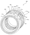
コイル樹脂構造体60の外観全体を図8に示す。コイル樹脂構造体60は、図8に示すように、負荷側(回転子の軸方向一方側に相当)に位置する短い円筒状の負荷側コイルエンド部62と、反負荷側(回転子の軸方向他方側に相当)に位置する短い円筒状の反負荷側コイルエンド部63と、それら負荷側コイルエンド部62と反負荷側コイルエンド部63との間に位置する中間部64と、を有している。このとき、コイル樹脂構造体60は、図7及び図8に示すように、中間部64の外径が両側の上記コイルエンド部分62,63の外径よりも小さくなっており、全体として円筒形に近い糸巻き(リール)型の形状を備えている。
コイル樹脂構造体60の外観全体を図8に示す。コイル樹脂構造体60は、図8に示すように、負荷側(回転子の軸方向一方側に相当)に位置する短い円筒状の負荷側コイルエンド部62と、反負荷側(回転子の軸方向他方側に相当)に位置する短い円筒状の反負荷側コイルエンド部63と、それら負荷側コイルエンド部62と反負荷側コイルエンド部63との間に位置する中間部64と、を有している。このとき、コイル樹脂構造体60は、図7及び図8に示すように、中間部64の外径が両側の上記コイルエンド部分62,63の外径よりも小さくなっており、全体として円筒形に近い糸巻き(リール)型の形状を備えている。
負荷側コイルエンド部62は、図8中に破線で示すように、各コイル41の上記一端側のターン部41c等の部分が被覆され内包される部位である(詳細は後述)。反負荷側コイルエンド部63は、図8中に破線で示すように、各コイル41の上記他端側の上記巻き始め端41s、上記巻き終わり端41e、及び上記ノーズ部41d等が被覆される部位である(詳細は後述)。
中間部64では、固定子鉄心32の複数のスロット31に収容される、略矩形板状の複数のスロット挿入部61が、周方向に配列されている。なお、後述するように、このスロット挿入部61は、各コイル41の上記第1直線部41a及び上記第2直線部41bが被覆され内包される部位である。
<一次被覆及び二次被覆による成形>
このコイル樹脂構造体60は、あらかじめ略円環状に配置した複数のコイル41のそれぞれに対し、表面にモールド樹脂による2回の樹脂成形が行われることにより、形成される。すなわち、1回目の樹脂成形により各コイル41の外側を覆う一次被覆層700(後述の図9等参照)が生成され、これによって一次成形体50が形成される。その後、2回目の樹脂成形により、当該一次被覆層700の外側を覆う二次被覆層800(図8参照)が生成され、これによって上記コイル樹脂構造体60が形成される。以下、上記一次被覆層700及び二次被覆層800の形成の詳細を、順を追って説明する。
このコイル樹脂構造体60は、あらかじめ略円環状に配置した複数のコイル41のそれぞれに対し、表面にモールド樹脂による2回の樹脂成形が行われることにより、形成される。すなわち、1回目の樹脂成形により各コイル41の外側を覆う一次被覆層700(後述の図9等参照)が生成され、これによって一次成形体50が形成される。その後、2回目の樹脂成形により、当該一次被覆層700の外側を覆う二次被覆層800(図8参照)が生成され、これによって上記コイル樹脂構造体60が形成される。以下、上記一次被覆層700及び二次被覆層800の形成の詳細を、順を追って説明する。
<一次成形体の成形>
上記一次成形体50について、図9、図10、及び図11により説明する。一次成形体50は、前述したように、略環状に配置された複数のコイル41それぞれの外側を一次被覆層700で被覆して構成されている(図11及び図10参照)。すなわち、一次成形体50は、図9に示すように、上記コイル樹脂構造体60の負荷側コイルエンド部62に対応した負荷側コイルエンド部52と、上記コイル樹脂構造体60の反負荷側コイルエンド部63に対応した反負荷側コイルエンド部53と、それら負荷側コイルエンド部52と反負荷側コイルエンド部53との間に位置し、上記コイル樹脂構造体60の中間部64に対応した中間部54と、を備えている。
上記一次成形体50について、図9、図10、及び図11により説明する。一次成形体50は、前述したように、略環状に配置された複数のコイル41それぞれの外側を一次被覆層700で被覆して構成されている(図11及び図10参照)。すなわち、一次成形体50は、図9に示すように、上記コイル樹脂構造体60の負荷側コイルエンド部62に対応した負荷側コイルエンド部52と、上記コイル樹脂構造体60の反負荷側コイルエンド部63に対応した反負荷側コイルエンド部53と、それら負荷側コイルエンド部52と反負荷側コイルエンド部53との間に位置し、上記コイル樹脂構造体60の中間部64に対応した中間部54と、を備えている。
上記一次成形体50の成形時には、上記略環状に配置された複数のコイル41を割り型の一次成形型にセットし、型の内部にモールド樹脂を注入して、各コイル41の外側にモールド樹脂による上記一次被覆層700が形成される(一次被覆工程に相当)。これにより、上記一次成形型の内部空間内で各コイル41がどの位置にありどのような姿勢となっているかを問わず、あらかじめ定められた所定の外径寸法の負荷側コイルエンド部52及び反負荷側コイルエンド部53が備えられ、さらにそれらコイルエンド部52,53間の中間にあらかじめ定められた所定の外径寸法の同一形状の複数個のスロット挿入部51が備えられた、上記一次成形体50を得ることができる。
<中間部>
中間部54では、上記コイル樹脂構造体60の複数のスロット挿入部61にそれぞれ対応した、略矩形板状の複数のスロット挿入部51が、周方向に配列されている。スロット挿入部51には、図10(a)に示すように、ある1つのコイル41の第2直線部41bと、別の1つのコイル41の第1直線部41aとが、径方向に重ねて積層されている。すなわち、この例では、上記第2直線部41bがスロット挿入部51の径方向外側(図10(a)、図10(c)の上側)に配置されるとともに、上記第1直線部41aがスロット挿入部51の径方向内側(図10(a)、図10(c)の下側)に配置されている(図4及び図8も参照)。そして、スロット挿入部51は、これら積層された第1直線部41a及び第2直線部41bの外側を一次被覆層700で覆うことにより、複数の突起部(後述)を備えた略矩形板状の形状を備えている。
中間部54では、上記コイル樹脂構造体60の複数のスロット挿入部61にそれぞれ対応した、略矩形板状の複数のスロット挿入部51が、周方向に配列されている。スロット挿入部51には、図10(a)に示すように、ある1つのコイル41の第2直線部41bと、別の1つのコイル41の第1直線部41aとが、径方向に重ねて積層されている。すなわち、この例では、上記第2直線部41bがスロット挿入部51の径方向外側(図10(a)、図10(c)の上側)に配置されるとともに、上記第1直線部41aがスロット挿入部51の径方向内側(図10(a)、図10(c)の下側)に配置されている(図4及び図8も参照)。そして、スロット挿入部51は、これら積層された第1直線部41a及び第2直線部41bの外側を一次被覆層700で覆うことにより、複数の突起部(後述)を備えた略矩形板状の形状を備えている。
詳細には、スロット挿入部51は、一次被覆層700による外面として、矩形平面の外面部701a,701aと、細長い矩形平面の外面部701b,701bと、を備えている。
外面部701aは、スロット挿入部51の、周方向に沿った両側(図10(b)中の上側と下側、図10(a)中の奥側と手前側、図10(c)中の左側と右側)にそれぞれ形成されている。各外面部701aには、当該外面部701aから所定寸法だけ上記周方向に突出して設けられた、一次被覆層700による突起部701a1が少なくとも1個(この例では2個)備えられている。
外面部701bは、スロット挿入部51の、径方向に沿った両側(図10(b)中の手前側と奥側、図10(a)中の上側と下側、図10(c)中の上側と下側)にそれぞれ形成されている。各外面部701bには、当該外面部701bから所定寸法だけ上記径方向に突出して設けられた、一次被覆層700による突起部701b1が少なくとも1個(この例では1個)ずつ備えられている。
<負荷側コイルエンド部>
負荷側コイルエンド部52は、複数のコイル41の軸方向一方側のターン部41c等の外側を一次被覆層700で覆うことにより、複数の突起部(後述)を備えた略円筒状に形成されている。
負荷側コイルエンド部52は、複数のコイル41の軸方向一方側のターン部41c等の外側を一次被覆層700で覆うことにより、複数の突起部(後述)を備えた略円筒状に形成されている。
詳細には、負荷側コイルエンド部52は、一次被覆層700による外面として、略円板状の外面部702aと、環状曲面の外面部702bと、環状曲面の外面部702cと、を備えている。
外面部702aは、前述の軸方向他方側(上記反負荷側に対応。図10(b)及び図10(a)中の左側、図10(c)中の手前側)に形成されている。外面部702aには、当該外面部702aから上記突起部701a1と同一寸法だけ突出して設けられた、一次被覆層700による突起部702a1が少なくとも1個(この例では2個)備えられている。
外面部702bは、径方向外側(図10(b)中の手前側、図10(a)及び図10(c)中の上側)に形成されている。外面部702bには、当該外面部702bから上記突起部701b1と同一寸法だけ突出して設けられた、一次被覆層700による突起部702b1が少なくとも1個(この例では1個)備えられている。
外面部702cは、径方向内側(図10(b)中の奥側、図10(a)及び図10(c)中の下側)に形成されている。外面部702cには、当該外面部702cから上記突起部701b1と同一寸法だけ突出して設けられた、一次被覆層700による突起部702c1が少なくとも1個(この例では1個)備えられている。
<反負荷側コイルエンド部>
反負荷側コイルエンド部53は、複数のコイル41の軸方向他方側のノーズ部41d等の外側を一次被覆層700で覆うことにより、複数の突起部(後述)を備えた略円筒状に形成されている。
反負荷側コイルエンド部53は、複数のコイル41の軸方向他方側のノーズ部41d等の外側を一次被覆層700で覆うことにより、複数の突起部(後述)を備えた略円筒状に形成されている。
詳細には、反負荷側コイルエンド部53は、一次被覆層700による外面として、に略円板状の外面部703aと、環状曲面の外面部703bと、環状曲面の外面部703cと、を備えている。
外面部703aは、前述の軸方向一方側(上記負荷側に対応。図10(b)及び図10(a)中の右側)に形成されている。外面部703aには、当該外面部703aから上記突起部701a1等と同一寸法だけ突出して設けられた、一次被覆層700による突起部703a1が少なくとも1個(この例では2個)備えられている。
外面部703bは、径方向外側(図10(b)中の手前側、図10(a)中の上側)に、形成されている。外面部703bには、当該外面部703bから上記突起部701a1等と同一寸法だけ突出して設けられた、一次被覆層700による突起部703b1が少なくとも1個(この例では1個)備えられている。
外面部703cは、径方向内側(図10(b)中の奥側、図10(a)中の下側)に、形成されている。外面部703cには、当該外面部703cから上記突起部701a1等と同一寸法だけ突出して設けられた、一次被覆層700による突起部703c1が少なくとも1個(この例では1個)備えられている。
<コイル樹脂構造体の成形>
上記一次成形体50からコイル樹脂構造体60を成形するときの被覆について、図12及び図8により説明する。前述のようにして一次成形体50を成形した後、当該一次成形体50を割り型の二次成形型にセットし、型の内部にモールド樹脂を注入して、一次成形体50の一次被覆層700の各外面部701a,701b,702a,702b,702c,703a,703b,703cに二次被覆層800をあらかじめ定められた所定厚さで被覆することにより、上記コイル樹脂構造体60が形成される(二次被覆工程に相当)。その際、一次成形体50は、上記二次成形型の内部において、前述の突起部701a,701b1、突起部702a1,702b1,702c1、突起部703a1,703b1,703c1を介し、上記径方向両側、上記周方向両側、及び上記軸方向両側を、当該二次成形型の内壁に対して支持される。この結果、上記の樹脂注入により、一次成形体50の全外表面(但し上記各突起部を除く)に、各突起部701a,701b1,702a1,702b1,702c1,703a1,703b1,703c1の高さ方向寸法と同じ厚さ(上記所定厚さに相当)の二次被覆層800が形成されて、上記コイル構造体60が完成する。なお、各突起部701a,701b1,702a1,702b1,702c1,703a1,703b1,703c1の高さ方向寸法は互いに同一でもよいが、そうでなくてもよい。
上記一次成形体50からコイル樹脂構造体60を成形するときの被覆について、図12及び図8により説明する。前述のようにして一次成形体50を成形した後、当該一次成形体50を割り型の二次成形型にセットし、型の内部にモールド樹脂を注入して、一次成形体50の一次被覆層700の各外面部701a,701b,702a,702b,702c,703a,703b,703cに二次被覆層800をあらかじめ定められた所定厚さで被覆することにより、上記コイル樹脂構造体60が形成される(二次被覆工程に相当)。その際、一次成形体50は、上記二次成形型の内部において、前述の突起部701a,701b1、突起部702a1,702b1,702c1、突起部703a1,703b1,703c1を介し、上記径方向両側、上記周方向両側、及び上記軸方向両側を、当該二次成形型の内壁に対して支持される。この結果、上記の樹脂注入により、一次成形体50の全外表面(但し上記各突起部を除く)に、各突起部701a,701b1,702a1,702b1,702c1,703a1,703b1,703c1の高さ方向寸法と同じ厚さ(上記所定厚さに相当)の二次被覆層800が形成されて、上記コイル構造体60が完成する。なお、各突起部701a,701b1,702a1,702b1,702c1,703a1,703b1,703c1の高さ方向寸法は互いに同一でもよいが、そうでなくてもよい。
コイル樹脂構造体60は、図8を用いて前述したように、中間部64と、負荷側コイルエンド部62と、反負荷側コイルエンド部63、とを備えている。このとき、中間部64では、一次成形体50の上記スロット挿入部51の一次被覆層700の外側を二次被覆層800により被覆した、矩形板状のスロット挿入部61が周方向に配列される。負荷側コイルエンド部62は、一次成形体50の上記負荷側コイルエンド部52の一次被覆層700の外側を、二次被覆層800により被覆することにより形成される。反負荷側コイルエンド部63は、一次成形体50の上記反負荷側コイルエンド部53の一次被覆層700の外側を、二次被覆層800により被覆することにより形成される。
<中間部>
前述したように、中間部64では、略矩形板状の複数のスロット挿入部61が、周方向に配列されている。スロット挿入部61は、上記一次被覆層700の外側をさらに被覆した上記二次被覆層800による外面として、矩形の外面部801a,801aと、細長い矩形の外面部801b,801bと、を備えている。
前述したように、中間部64では、略矩形板状の複数のスロット挿入部61が、周方向に配列されている。スロット挿入部61は、上記一次被覆層700の外側をさらに被覆した上記二次被覆層800による外面として、矩形の外面部801a,801aと、細長い矩形の外面部801b,801bと、を備えている。
外面部801aは、スロット挿入部61の、周方向に沿った両側(図12(b)中の上側と下側、図12(a)中の奥側と手前側、図12(c)中の左側と右側)において、上記一次成形体50の一次被覆層700による外面部701aの外表面を、前述した手法で突起部701a1の高さ寸法の厚さの二次被覆層800でさらに被覆することにより、形成されている。
外面部801bは、スロット挿入部61の、径方向に沿った両側(図12(a)中の手前側と奥側、図10(a)中の上側と下側、図10(c)中の上側と下側)において、上記一次成形体50の一次被覆層700による外面部701bの外表面を、前述した手法で突起部701b1の高さ寸法の厚さの二次被覆層800でさらに被覆することにより、形成されている。
<負荷側コイルエンド部>
負荷側コイルエンド部62は、上記一次被覆層700の外側をさらに被覆した上記二次被覆層800による外面として、略円板状の外面部802aと、環状の外面部802bと、環状曲面の外面部802cと、を備えている。
負荷側コイルエンド部62は、上記一次被覆層700の外側をさらに被覆した上記二次被覆層800による外面として、略円板状の外面部802aと、環状の外面部802bと、環状曲面の外面部802cと、を備えている。
外面部802aは、上記軸方向他方側(図12(a)及び図12(b)中の左側、図12(c)の手前側)において、上記一次成形体50の一次被覆層700による外面部702aの外表面を、前述した手法で突起部702a1の高さ寸法の厚さの二次被覆層800でさらに被覆することにより、形成されている。
外面部802bは、上記径方向外側(図12(b)中の手前側、図12(a)及び図12(c)中の上側)において、上記一次成形体50の一次被覆層700による外面部702bの外表面を、前述した手法で突起部702b1の高さ寸法の厚さの二次被覆層800でさらに被覆することにより、形成されている。
外面部802cは、上記径方向内側(図12(b)中の奥側、図12(a)及び図12(c)中の下側)において、上記一次成形体50の一次被覆層700による外面部702cの外表面を、前述した手法で突起部702c1の高さ寸法の厚さの二次被覆層800でさらに被覆することにより、形成されている。
<反負荷側コイルエンド部>
反負荷側コイルエンド部63は、上記一次被覆層700の外側をさらに被覆した上記二次被覆層800による外面として、略円板の外面部803aと、環状曲面の外面部803bと、環状曲面の外面部803cと、を備えている。
反負荷側コイルエンド部63は、上記一次被覆層700の外側をさらに被覆した上記二次被覆層800による外面として、略円板の外面部803aと、環状曲面の外面部803bと、環状曲面の外面部803cと、を備えている。
外面部803aは、上記軸方向一方側(図12(a)及び図12(b)中の右側)において、上記一次成形体50の一次被覆層700による外面部703aの外表面を、前述した手法で突起部703a1の高さ寸法の厚さの二次被覆層800でさらに被覆することにより、形成されている。
外面部803bは、上記径方向外側(図12(b)中の手前側、図12(a)及び図12(c)中の上側)において、上記一次成形体50の一次被覆層700による外面部702bの外表面を、前述した手法で突起部702b1の高さ寸法の厚さの二次被覆層800でさらに被覆することにより、形成されている。
外面部803cは、上記径方向内側(図12(b)中の奥側、図12(a)及び図12(c)中の下側)において、上記一次成形体50の一次被覆層700による外面部703cの外表面を、前述した手法で突起部703c1の高さ寸法の厚さの二次被覆層800でさらに被覆することにより、形成されている。
(第2実施形態の効果)
以上のように構成した本実施形態によっても、上記第1実施形態と同様の効果を得る。すなわち、主ラインとは別ラインである副ラインにおいて複数のコイル41により高占積率にコイル樹脂構造体45を構築することで、コイル41自体の発熱を下げて、回転電機10の冷却性能を向上することができる。また、主ラインでのモールド樹脂成形作業を不要として、製造時間を大幅に低減することができる。さらに、回転電機10が不要となり廃棄されるとき容易に分解することができる。特に、例えば固定子鉄心35側に使用される鉄材とコイル41の導体42に使用される銅材とを容易に分離して、リサイクル性を飛躍的に向上することができる。
以上のように構成した本実施形態によっても、上記第1実施形態と同様の効果を得る。すなわち、主ラインとは別ラインである副ラインにおいて複数のコイル41により高占積率にコイル樹脂構造体45を構築することで、コイル41自体の発熱を下げて、回転電機10の冷却性能を向上することができる。また、主ラインでのモールド樹脂成形作業を不要として、製造時間を大幅に低減することができる。さらに、回転電機10が不要となり廃棄されるとき容易に分解することができる。特に、例えば固定子鉄心35側に使用される鉄材とコイル41の導体42に使用される銅材とを容易に分離して、リサイクル性を飛躍的に向上することができる。
また、本実施形態では、上記に加え、以下の効果を得る。すなわち、本実施形態では、空芯コイルであるコイル41の外側に一次被覆層700が形成された後、さらにその外側に二次被覆層800が形成されることにより、コイル樹脂構造体60が製造される。一次被覆工程では、コイル41を上記一次成形型に入れて型の内部に樹脂を注入し、コイル41を一次被覆層700で覆う。その際には、一次被覆層700で覆われた複数のコイル41を内包する一次成形体50の外形状寸法(言い換えれば上記成形型の内部に形成される空間の形状寸法)を管理する。すなわち、当該一次成形体50の内部で、各コイル41がどのように偏っているか、どの位置にあるかは不問とする。
そして、上記一次成形体50を、さらに別の二次成形型に入れて型の内部に樹脂を注入し、一次成形体50を二次被覆層800で覆う。上記のように一次成形体50の外形状寸法は上記一次成形型によって高精度に管理されている(一次成形体50内部での各コイル41の位置にかかわらず一次成形体50の外形状寸法はすべて同一である)ので、二次被覆層800を、上記一次成形体51の外側に、均一な厚さで形成することができる。
以上のようにして、一次被覆層700により外形状寸法を高精度に管理された一次成形体50の外側に、均一に二次被覆層800が形成される。これにより、コイル41の外周側に形成される樹脂の被覆層(一次被覆層700+二次被覆層800)において、最低限必要な厚さを確保することができる。
また、上記一次被覆層700の形成の前段階である、コイル41の製造時に巻線(導体42)が巻回される際(あるいはその後にプレス成形された際)において、例えば巻線の浮き上がりが生じる等により外側にはみだす形となったりゆがんだ形状となったりして、必ずしも精度よく所望の外形寸法とはならない(以下適宜、「不定形状」という)場合があり得る。この第2実施形態では、このような場合であっても、上記不定形状のコイル41を一次成形型の内部に収納して一次成形型を閉じることで、強制的に前述の高精度な一次成形体50の外形状寸法を実現することができる。但しこの場合、コイル41のうち上記一次成形型により接触されて押圧される部位は、樹脂が流入せずに一次被覆層700の厚さが0(またはそれに近い値)となる。しかしながら前述のように、その後一次被覆層700の外側全域にわたって所定厚さの二次被覆層800が均一に形成されるので、当該部位についても確実に樹脂被覆層を形成することができる。
以上の結果、本実施形態によれば、コイル41を被覆する際の被覆層の厚さのばらつきを抑制し、均一化を図ることができる。
また、本実施形態では特に、一次被覆層700において、スロット挿入部51の外面(外面部701a及び外面部701b)、負荷側コイルエンド部52の外面(外面部702a、外面部702b、及び外面部702c)、反負荷側コイルエンド部53の外面(外面部703a、外面部703b、及び外面部703c)に対し、各外面部から所定寸法だけ突出して複数の突起部(突起部701a1,701b1、突起部702a1,702b1,702c1、及び、突起部703a1,703b1,703c1)が設けられている。そして、二次被覆層800は、上記一次被覆層700の外側を、上記所定寸法(各突起部の高さ方向寸法)に等しい厚さで覆うように設けられている。
すなわち、本実施形態においては、一次被覆層700が形成された後の一次成形体50には、所定寸法(二次被覆層800の厚さ寸法に等しい)の上記突起部701a1,701b1,702a1,702b1,702c1,703a1,703b1,703c1が各外面部に備えられる。これにより、二次被覆層800を形成するために二次成形型に一次成形体50を収納する際、前述したように、二次成形型の内壁に対し、上記突起部701a1,701b1,702a1,702b1,702c1,703a1,703b1,703c1によって一次成形体50全体を確実に支持することができる。
また本実施形態では特に、上記突起部701a1,701b1,702a1,702b1,702c1,703a1,703b1,703c1によって支持された状態の一次成形体50の周囲に樹脂が注入充填されることで、上記二次被覆層800は、上記複数の突起部を除く上記一次被覆層700の外側を、上記所定寸法に等しい厚さで覆う。これにより、二次成形型に収納された一次成形体50の周囲のうち、突起部701a1,701b1,702a1,702b1,702c1,703a1,703b1,703c1以外の部位に二次被覆層800を均一に確実に形成することができる。
また、本実施形態では特に、コイル樹脂構造体60は、複数のスロット31に収容されるスロット挿入部61を備える中間部64の外径が、回転子30の軸方向に沿った両側のコイルエンド部62,63の外径よりも小さい。これには以下のような意義がある。
すなわち、前述のようにして複数のコイル41が固定子鉄心32に配置されるとき、図6に示すように、各コイル41のうちスロット31に収容される部分(コイルエンド部62,63以外の中間部64)の径方向内側に回転子20が配置され、また各コイル41の上記中間部64の上記スロット挿入部61の径方向外側には、回転電機10Aの筐体への支持構造が設けられる。そこで本実施形態では、コイル樹脂構造体60において、上記のように径方向内側・外側に別途の部材・構造物が配置される中間部64の外径を、そのような配置のないコイルエンド部62,63の外径よりも小さくする。これにより、回転電機全体10Aが径方向へ大型化するのを防止し、小型化を図ることができる。
(第3実施形態)
次に、図13を用いて、第3実施形態の回転電機について説明する。図13に示すように、本実施形態の回転電機10Bは、固定子30の内側に回転子20を備えたリラクタンスモータである。第1実施形態と同等の部分には同一の符号を付し、適宜説明を省略又は簡略化する。
次に、図13を用いて、第3実施形態の回転電機について説明する。図13に示すように、本実施形態の回転電機10Bは、固定子30の内側に回転子20を備えたリラクタンスモータである。第1実施形態と同等の部分には同一の符号を付し、適宜説明を省略又は簡略化する。
図13に示す回転電機10Bにおいて、固定子30は、固定子鉄心35を備えている。固定子鉄心35では、上記第1実施形態と同様、複数(この例では72個)の分割コア要素36が、固定子30のフレーム11(上記図2参照)の内周面に沿いつつ全周にわたって配列されている。各分割コア要素36は、径方向内側に、横断面が先細台形状となるティース37を備えている。そして、隣り合う分割コア要素36,36の上記ティース37,37の間に、横断面が矩形状(長方形)のスロット38が形成されている。
本実施形態では、上記第1実施形態と同様、複数(この例では72個)の上記スロット38に複数(この例では72個)のコイル41が挿入(収容)される。その際、上記同様、2つのコイル41,41同士の間に、分割コア要素36のティース37を嵌め込む空隙43が形成されるように、各コイル41は位置をずらして重ね巻きされる。そして、重ね巻きされた72個のコイル41は、図示しないモールド樹脂で一体的に樹脂成形され、略円筒状の1つのコイル樹脂構造体45が形成される(図示省略。上記図8も参照)。
このとき、本実施形態では、ティース37の横断面形状を先細状とすることで、スロット38の横断面形状は矩形状(長方形)のままである。この結果、コイル41の第1直線部41a及び第2直線部41bには、上記第1実施形態のような外形状に対する加圧成形は行われない。
本実施形態においても、上記第1実施形態と同様、コイル樹脂構造体45の隣り合うコイル41,41の間の各空隙43に、コイル樹脂構造体45の外周側から分割コア要素36のティース37が(コイル樹脂構造体45の全周にわたって)嵌めこまれる。これにより、72個の分割コア要素36によって円環状の固定子鉄心35が構築される。また、隣り合う2つの分割コア要素36,36のティース37,37間に形成された各スロット38の上記内周段に、コイル樹脂構造体45のコイル41の第1直線部が収容され、かつ、各スロット38の上記外周段に、コイル樹脂構造体45の他のコイル41の第2直線部が収容されつつ、コイル樹脂構造体45と上記固定子鉄心35が組み立てられる。なお、本実施形態の上記第1直線部は、上記第1実施形態の第1直線部41aに相当しているが、4層の導体42の各層は同一の略長方形横断面形状を備えている。また、本実施形態の上記第2直線部は、上記第2実施形態の第2直線部41bに相当しているが、4層の導体42の各層は同一の略長方形横断面形状を備えている。このようにして固定子30が組み立てられる。
なお、回転子20の回転子鉄心22には、周方向に沿った複数極(本例では8極)に各極3個ずつ、合計24個の空隙部25が設けられている。空隙部25は、径方向内側に凸に湾曲している。この空隙部25により回転子鉄心の磁路抵抗に違いができるため、リラクタンストルクを発生する。
以上のように構成した本実施形態によっても、上記第1実施形態と同様の効果を得る。すなわち、主ラインとは別ラインである副ラインにおいて複数のコイル41により高占積率にコイル樹脂構造体45を構築することで、コイル41自体の発熱を下げて、回転電機10の冷却性能を向上することができる。また、主ラインでのモールド樹脂成形作業を不要として、製造時間を大幅に低減することができる。さらに、回転電機10が不要となり廃棄されるとき容易に分解することができる。特に、例えば固定子鉄心35側に使用される鉄材とコイル41の導体42に使用される銅材とを容易に分離して、リサイクル性を飛躍的に向上することができる。
また、以上既に述べた以外にも、上記実施形態による手法を適宜組み合わせて利用しても良い。
その他、一々例示はしないが、その趣旨を逸脱しない範囲内において、種々の変更が加えられて実施されるものである。
10 回転電機
10A 回転電機
10B 回転電機
20 回転子
23 永久磁石
30 固定子
31 スロット
32 固定子鉄心
33 分割コア要素
35 固定子鉄心
36 分割コア要素
34 ティース
37 ティース
38 スロット
41 コイル(空芯コイル)
41a 第1直線部(周方向一方側部分)
41b 第2直線部(周方向他方側部分)
42 導体
43 空隙
45 コイル樹脂構造体
50 一次成形体
51 スロット挿入部
52 負荷側コイルエンド
53 反負荷側コイルエンド
54 中間部
60 コイル樹脂構造体
61 スロット挿入部
62 負荷側コイルエンド
63 負荷側コイルエンド
64 中間部
700 一次被覆層
701a 外面
701b 外面
701a1 突起部
701b1 突起部
702a~c 外面
702a1 突起部
702b1 突起部
702c1 突起部
703a~c 外面
703a1 外面
703b1 外面
703c1 外面
800 二次被覆層
10A 回転電機
10B 回転電機
20 回転子
23 永久磁石
30 固定子
31 スロット
32 固定子鉄心
33 分割コア要素
35 固定子鉄心
36 分割コア要素
34 ティース
37 ティース
38 スロット
41 コイル(空芯コイル)
41a 第1直線部(周方向一方側部分)
41b 第2直線部(周方向他方側部分)
42 導体
43 空隙
45 コイル樹脂構造体
50 一次成形体
51 スロット挿入部
52 負荷側コイルエンド
53 反負荷側コイルエンド
54 中間部
60 コイル樹脂構造体
61 スロット挿入部
62 負荷側コイルエンド
63 負荷側コイルエンド
64 中間部
700 一次被覆層
701a 外面
701b 外面
701a1 突起部
701b1 突起部
702a~c 外面
702a1 突起部
702b1 突起部
702c1 突起部
703a~c 外面
703a1 外面
703b1 外面
703c1 外面
800 二次被覆層
Claims (8)
- 回転子と、前記回転子の外周側を囲むように設けられた固定子と、を有し、
前記固定子は、周方向に複数のスロットが配列された固定子鉄心と、前記複数のスロットに収容される複数のコイルと、を有する回転電機であって、
前記固定子鉄心は、
分割コア要素を周方向に複数個配列して構成されており、
前記複数のコイルのそれぞれは、
周方向一方側部分が前記複数個のスロットのうちの1つのスロットに収容されかつ周方向他方側部分が前記複数個のスロットのうち前記1つのスロットとは異なる他のスロットに収容されて、各コイルの周方向位置が順次ずらされて重ね巻きされた空芯コイルにより構成されており、
かつ、
複数の前記空芯コイルを、一体的に樹脂成形し、コイル樹脂構造体を形成し、
前記コイル樹脂構造体に、前記複数の分割コア要素を組み付けることにより、前記固定子鉄心を構成した
ことを特徴とする回転電機。 - 前記コイル樹脂構造体は、
前記空芯コイルの外側を覆うように設けられた一次被覆層と、
前記一次被覆層の外側を覆うように設けられた二次被覆層と、
を備えている
ことを特徴とする請求項1記載の回転電機。 - 前記一次被覆層は、
曲面及び平面の少なくとも一方を、複数個備えた外面と、
前記外面から所定寸法だけ突出して設けられた複数の突起部と、
を備えており、
前記二次被覆層は、
前記一次被覆層の外側を、前記所定寸法に等しい厚さで覆うように設けられている
ことを特徴とする請求項2記載の回転電機。 - 前記二次被覆層は、
前記複数の突起部を除く前記一次被覆層の外側を、前記所定寸法に等しい厚さで覆う
ことを特徴とする請求項3記載の回転電機。 - 前記コイル樹脂構造体は、
前記複数のスロットに収容される部分の外径が、前記回転子の軸方向に沿った両側のコイルエンド部分の外径よりも小さい
ことを特徴とする請求項2乃至請求項4のいずれか1項記載の回転電機。 - 前記複数のコイルのそれぞれは、
加圧成形された前記空芯コイルにより構成されている
ことを特徴とする請求項2乃至請求項5のいずれか1項記載の回転電機。 - 回転子と、前記回転子の外周側を囲むように設けられた固定子と、を有し、
前記固定子が、
周方向に複数のスロットが配列された固定子鉄心と、前記複数のスロットに収容される複数のコイルと、を有し、
前記固定子鉄心が、
分割コア要素を周方向に複数個配列して構成されている回転電機の製造方法であって、
複数の空芯コイルを、それぞれの周方向一方側部分が前記複数個のスロットのうちの1つのスロットに収容されかつそれぞれの周方向他方側部分が前記複数個のスロットのうち前記1つのスロットとは異なる他のスロットに収容されるようにしつつ、各コイルの周方向位置が順次ずれるように重ね巻きする重ね巻き工程と、
前記重ね巻きされた前記複数の空芯コイルを一体的に樹脂成形し、コイル樹脂構造体を形成する樹脂成形工程と、
前記コイル樹脂構造体に、前記複数の分割コア要素を組み付けることにより、前記固定子鉄心を構成する組み付け工程と、
を有することを特徴とする回転電機の製造方法。 - 前記樹脂成形工程は、
前記コイル樹脂構造体の前記複数の空芯コイルの外側を覆うように一次被覆層を形成する一次被覆工程と、
前記一次被覆層の外側を覆うように二次被覆層を形成する二次被覆工程と、
を備える
ことを特徴とする請求項7記載の回転電機の製造方法。
Priority Applications (3)
| Application Number | Priority Date | Filing Date | Title |
|---|---|---|---|
| CN201280073780.1A CN104364994B (zh) | 2012-06-08 | 2012-12-20 | 旋转电机及旋转电机的制造方法 |
| JP2014519794A JP5831775B2 (ja) | 2012-06-08 | 2012-12-20 | 回転電機及び回転電機の製造方法 |
| US14/561,714 US9698639B2 (en) | 2012-06-08 | 2014-12-05 | Rotating electrical machine and method for manufacturing rotating electrical machine |
Applications Claiming Priority (2)
| Application Number | Priority Date | Filing Date | Title |
|---|---|---|---|
| JP2012131072 | 2012-06-08 | ||
| JP2012-131072 | 2012-06-08 |
Related Child Applications (1)
| Application Number | Title | Priority Date | Filing Date |
|---|---|---|---|
| US14/561,714 Continuation US9698639B2 (en) | 2012-06-08 | 2014-12-05 | Rotating electrical machine and method for manufacturing rotating electrical machine |
Publications (1)
| Publication Number | Publication Date |
|---|---|
| WO2013183188A1 true WO2013183188A1 (ja) | 2013-12-12 |
Family
ID=49711599
Family Applications (1)
| Application Number | Title | Priority Date | Filing Date |
|---|---|---|---|
| PCT/JP2012/083161 Ceased WO2013183188A1 (ja) | 2012-06-08 | 2012-12-20 | 回転電機及び回転電機の製造方法 |
Country Status (4)
| Country | Link |
|---|---|
| US (1) | US9698639B2 (ja) |
| JP (1) | JP5831775B2 (ja) |
| CN (1) | CN104364994B (ja) |
| WO (1) | WO2013183188A1 (ja) |
Cited By (4)
| Publication number | Priority date | Publication date | Assignee | Title |
|---|---|---|---|---|
| JP2016208745A (ja) * | 2015-04-24 | 2016-12-08 | 株式会社安川電機 | 回転電機、回転電機の製造方法、固定子コイル、コイル樹脂構造体 |
| JP2017028963A (ja) * | 2015-07-28 | 2017-02-02 | 株式会社安川電機 | 回転電機、回転電機の製造方法、固定子コイル、コイル樹脂構造体 |
| JP2021136764A (ja) * | 2020-02-26 | 2021-09-13 | 日本発條株式会社 | ステータ分割体、ステータ、モータ及びステータ分割体の製造方法 |
| WO2025005126A1 (ja) * | 2023-06-30 | 2025-01-02 | 株式会社アスター | コイルユニット、モータ部材、コイルユニットの製造方法およびモータ部材の製造方法 |
Families Citing this family (8)
| Publication number | Priority date | Publication date | Assignee | Title |
|---|---|---|---|---|
| JP2017229120A (ja) * | 2016-06-20 | 2017-12-28 | 株式会社ジェイテクト | シンクロナスリラクタンスモータ |
| JP6799962B2 (ja) * | 2016-08-03 | 2020-12-16 | 本田技研工業株式会社 | バスバーユニット |
| CA3035592A1 (en) | 2016-09-02 | 2018-03-08 | Ats Automation Tooling Systems Inc. | Method and system for assembling hairpin conductors with a stator core |
| JP6605517B2 (ja) * | 2017-01-27 | 2019-11-13 | 株式会社豊田中央研究所 | 回転電機 |
| AT521301B1 (de) * | 2018-05-29 | 2020-04-15 | Miba Ag | Stator mit Isolationsschicht |
| CN108847756B (zh) * | 2018-08-06 | 2024-07-16 | 南京磁谷科技股份有限公司 | 一种大功率高速电机外插式拼接定子的装配工装 |
| EP3719962A1 (en) * | 2019-04-01 | 2020-10-07 | LIM-Tech Limited | Electromotive machine |
| JP2023011308A (ja) * | 2021-07-12 | 2023-01-24 | 日立Astemo株式会社 | 回転電機および回転電機の固定子 |
Citations (5)
| Publication number | Priority date | Publication date | Assignee | Title |
|---|---|---|---|---|
| JP2003304656A (ja) * | 2002-04-10 | 2003-10-24 | Nippon Steel Corp | 回転電機のステータ構造およびステータの製造方法 |
| JP2007135326A (ja) * | 2005-11-11 | 2007-05-31 | Sumitomo Electric Ind Ltd | 電機子の製造方法 |
| JP2009153287A (ja) * | 2007-12-20 | 2009-07-09 | Sumitomo Electric Ind Ltd | 分割ステータ用モールドコイル、ステータ用モールドコイルの製造方法及びステータ用モールドコイル成形用金型装置 |
| JP2010142075A (ja) * | 2008-12-15 | 2010-06-24 | Toyota Motor Corp | 固定子構造及び固定子製造方法 |
| JP2011259566A (ja) * | 2010-06-07 | 2011-12-22 | Toyota Motor Corp | 固定子の製造方法 |
Family Cites Families (11)
| Publication number | Priority date | Publication date | Assignee | Title |
|---|---|---|---|---|
| US3254150A (en) * | 1961-07-24 | 1966-05-31 | Westinghouse Electric Corp | Electrical coils for refrigerating apparatus |
| US4137275A (en) * | 1976-04-27 | 1979-01-30 | Westinghouse Electric Corp. | Latent accelerators for curing epoxy resins |
| US4113791A (en) * | 1977-03-03 | 1978-09-12 | Westinghouse Electric Corp. | Fluid solventless epoxy-anhydride compositions containing metal acetylacetonate accelerators and organic carboxylic acid co-accelerators |
| US4224541A (en) * | 1978-05-26 | 1980-09-23 | Westinghouse Electric Corp. | Fluid solventless epoxy-anhydride compositions containing metal acetylacetonate accelerators and organic carboxylic acid co-accelerators for use on an electrical member |
| JP3791492B2 (ja) | 2002-12-25 | 2006-06-28 | 株式会社日立製作所 | 回転電機及び電動車両並びに樹脂のインサート成形方法 |
| JP4595442B2 (ja) | 2004-08-24 | 2010-12-08 | 日立工機株式会社 | 電動モータ、それを備える電動工具及び電動モータの製造方法 |
| CN101075756A (zh) * | 2006-05-19 | 2007-11-21 | 南京乐金熊猫电器有限公司 | 电机 |
| JP2009278845A (ja) | 2008-05-19 | 2009-11-26 | Toyota Motor Corp | 三相交流回転電機 |
| JP5817964B2 (ja) * | 2011-03-22 | 2015-11-18 | 日立工機株式会社 | ディスクモータ及びそれを備えた電動作業機 |
| JP5926532B2 (ja) * | 2011-10-27 | 2016-05-25 | コベルコ建機株式会社 | 電動機 |
| JP5718854B2 (ja) * | 2012-05-09 | 2015-05-13 | トヨタ自動車株式会社 | 回転電機用膨張シート、回転電機用膨張シートを用いた回転電機用ステータおよび回転電機用ステータの製造方法 |
-
2012
- 2012-12-20 WO PCT/JP2012/083161 patent/WO2013183188A1/ja not_active Ceased
- 2012-12-20 CN CN201280073780.1A patent/CN104364994B/zh active Active
- 2012-12-20 JP JP2014519794A patent/JP5831775B2/ja active Active
-
2014
- 2014-12-05 US US14/561,714 patent/US9698639B2/en active Active
Patent Citations (5)
| Publication number | Priority date | Publication date | Assignee | Title |
|---|---|---|---|---|
| JP2003304656A (ja) * | 2002-04-10 | 2003-10-24 | Nippon Steel Corp | 回転電機のステータ構造およびステータの製造方法 |
| JP2007135326A (ja) * | 2005-11-11 | 2007-05-31 | Sumitomo Electric Ind Ltd | 電機子の製造方法 |
| JP2009153287A (ja) * | 2007-12-20 | 2009-07-09 | Sumitomo Electric Ind Ltd | 分割ステータ用モールドコイル、ステータ用モールドコイルの製造方法及びステータ用モールドコイル成形用金型装置 |
| JP2010142075A (ja) * | 2008-12-15 | 2010-06-24 | Toyota Motor Corp | 固定子構造及び固定子製造方法 |
| JP2011259566A (ja) * | 2010-06-07 | 2011-12-22 | Toyota Motor Corp | 固定子の製造方法 |
Non-Patent Citations (1)
| Title |
|---|
| KAZUMI NAGATOMO: "Denji Actuator no Seizo Hoho", JOURNAL OF TECHNICAL DISCLOSURE, 18 February 2003 (2003-02-18), JAPAN INSTITUTE OF INVENTION AND INNOVATION * |
Cited By (5)
| Publication number | Priority date | Publication date | Assignee | Title |
|---|---|---|---|---|
| JP2016208745A (ja) * | 2015-04-24 | 2016-12-08 | 株式会社安川電機 | 回転電機、回転電機の製造方法、固定子コイル、コイル樹脂構造体 |
| JP2017028963A (ja) * | 2015-07-28 | 2017-02-02 | 株式会社安川電機 | 回転電機、回転電機の製造方法、固定子コイル、コイル樹脂構造体 |
| JP2021136764A (ja) * | 2020-02-26 | 2021-09-13 | 日本発條株式会社 | ステータ分割体、ステータ、モータ及びステータ分割体の製造方法 |
| JP7569600B2 (ja) | 2020-02-26 | 2024-10-18 | 日本発條株式会社 | ステータ及びモータ |
| WO2025005126A1 (ja) * | 2023-06-30 | 2025-01-02 | 株式会社アスター | コイルユニット、モータ部材、コイルユニットの製造方法およびモータ部材の製造方法 |
Also Published As
| Publication number | Publication date |
|---|---|
| JPWO2013183188A1 (ja) | 2016-01-28 |
| CN104364994B (zh) | 2017-06-30 |
| US20150084448A1 (en) | 2015-03-26 |
| US9698639B2 (en) | 2017-07-04 |
| JP5831775B2 (ja) | 2015-12-09 |
| CN104364994A (zh) | 2015-02-18 |
Similar Documents
| Publication | Publication Date | Title |
|---|---|---|
| JP5831775B2 (ja) | 回転電機及び回転電機の製造方法 | |
| CN102801242B (zh) | 旋转电机 | |
| US10763716B2 (en) | Axial-air-gap dynamo-electric machine with a tubular-shaped stator bobbin | |
| US7812498B2 (en) | Stator of electric rotating machine and electric rotating machine | |
| CN105723596B (zh) | 磁感应式电动机及其制造方法 | |
| WO2015145901A1 (ja) | アキシャルエアギャップ型電動機及び電動機用ボビン | |
| JP7449657B2 (ja) | モータ | |
| JP2013208021A (ja) | ステータコア | |
| TW201742356A (zh) | 軸向間隙型旋轉電機 | |
| CN107408859B (zh) | 轴向间隙型旋转电机和定子 | |
| JP2016208745A (ja) | 回転電機、回転電機の製造方法、固定子コイル、コイル樹脂構造体 | |
| TWI673936B (zh) | 軸向間隙型旋轉電機 | |
| US8823240B2 (en) | Stator and rotating electrical machine | |
| EP3039776B1 (en) | Electrical machine with stator housing having improved cooling efficiency | |
| WO2017158700A1 (ja) | 回転電機、回転電機の製造方法 | |
| CN205178690U (zh) | 电机定子、永磁发电机 | |
| JP2015027175A (ja) | 回転電機及び回転電機の製造方法 | |
| JP5916650B2 (ja) | 回転電機の電機子、回転電機、回転電機のコイルの製造方法、回転電機の電機子の製造方法 | |
| JP4926192B2 (ja) | 電動機の固定子 | |
| CN114270664A (zh) | 线圈、定子、电动机、以及定子的制造方法 | |
| TW202032586A (zh) | 電樞的線圈架構造 | |
| JP2009148141A (ja) | 磁性体部品 | |
| JP2013099103A (ja) | ロータ及びモータ | |
| JPS6285662A (ja) | 誘導電動機 | |
| JP2017103923A (ja) | ステータの製造方法 |
Legal Events
| Date | Code | Title | Description |
|---|---|---|---|
| 121 | Ep: the epo has been informed by wipo that ep was designated in this application |
Ref document number: 12878482 Country of ref document: EP Kind code of ref document: A1 |
|
| ENP | Entry into the national phase |
Ref document number: 2014519794 Country of ref document: JP Kind code of ref document: A |
|
| NENP | Non-entry into the national phase |
Ref country code: DE |
|
| 122 | Ep: pct application non-entry in european phase |
Ref document number: 12878482 Country of ref document: EP Kind code of ref document: A1 |