WO2013176010A1 - Composant coulissant - Google Patents
Composant coulissant Download PDFInfo
- Publication number
- WO2013176010A1 WO2013176010A1 PCT/JP2013/063499 JP2013063499W WO2013176010A1 WO 2013176010 A1 WO2013176010 A1 WO 2013176010A1 JP 2013063499 W JP2013063499 W JP 2013063499W WO 2013176010 A1 WO2013176010 A1 WO 2013176010A1
- Authority
- WO
- WIPO (PCT)
- Prior art keywords
- ultra
- sliding
- shallow
- groove
- fluid
- Prior art date
Links
Images


Classifications
-
- F—MECHANICAL ENGINEERING; LIGHTING; HEATING; WEAPONS; BLASTING
- F16—ENGINEERING ELEMENTS AND UNITS; GENERAL MEASURES FOR PRODUCING AND MAINTAINING EFFECTIVE FUNCTIONING OF MACHINES OR INSTALLATIONS; THERMAL INSULATION IN GENERAL
- F16J—PISTONS; CYLINDERS; SEALINGS
- F16J15/00—Sealings
- F16J15/16—Sealings between relatively-moving surfaces
- F16J15/40—Sealings between relatively-moving surfaces by means of fluid
-
- F—MECHANICAL ENGINEERING; LIGHTING; HEATING; WEAPONS; BLASTING
- F16—ENGINEERING ELEMENTS AND UNITS; GENERAL MEASURES FOR PRODUCING AND MAINTAINING EFFECTIVE FUNCTIONING OF MACHINES OR INSTALLATIONS; THERMAL INSULATION IN GENERAL
- F16C—SHAFTS; FLEXIBLE SHAFTS; ELEMENTS OR CRANKSHAFT MECHANISMS; ROTARY BODIES OTHER THAN GEARING ELEMENTS; BEARINGS
- F16C17/00—Sliding-contact bearings for exclusively rotary movement
- F16C17/02—Sliding-contact bearings for exclusively rotary movement for radial load only
-
- F—MECHANICAL ENGINEERING; LIGHTING; HEATING; WEAPONS; BLASTING
- F16—ENGINEERING ELEMENTS AND UNITS; GENERAL MEASURES FOR PRODUCING AND MAINTAINING EFFECTIVE FUNCTIONING OF MACHINES OR INSTALLATIONS; THERMAL INSULATION IN GENERAL
- F16C—SHAFTS; FLEXIBLE SHAFTS; ELEMENTS OR CRANKSHAFT MECHANISMS; ROTARY BODIES OTHER THAN GEARING ELEMENTS; BEARINGS
- F16C33/00—Parts of bearings; Special methods for making bearings or parts thereof
- F16C33/72—Sealings
- F16C33/74—Sealings of sliding-contact bearings
- F16C33/741—Sealings of sliding-contact bearings by means of a fluid
- F16C33/743—Sealings of sliding-contact bearings by means of a fluid retained in the sealing gap
-
- F—MECHANICAL ENGINEERING; LIGHTING; HEATING; WEAPONS; BLASTING
- F16—ENGINEERING ELEMENTS AND UNITS; GENERAL MEASURES FOR PRODUCING AND MAINTAINING EFFECTIVE FUNCTIONING OF MACHINES OR INSTALLATIONS; THERMAL INSULATION IN GENERAL
- F16J—PISTONS; CYLINDERS; SEALINGS
- F16J15/00—Sealings
- F16J15/16—Sealings between relatively-moving surfaces
- F16J15/34—Sealings between relatively-moving surfaces with slip-ring pressed against a more or less radial face on one member
- F16J15/3404—Sealings between relatively-moving surfaces with slip-ring pressed against a more or less radial face on one member and characterised by parts or details relating to lubrication, cooling or venting of the seal
- F16J15/3408—Sealings between relatively-moving surfaces with slip-ring pressed against a more or less radial face on one member and characterised by parts or details relating to lubrication, cooling or venting of the seal at least one ring having an uneven slipping surface
- F16J15/3412—Sealings between relatively-moving surfaces with slip-ring pressed against a more or less radial face on one member and characterised by parts or details relating to lubrication, cooling or venting of the seal at least one ring having an uneven slipping surface with cavities
- F16J15/3416—Sealings between relatively-moving surfaces with slip-ring pressed against a more or less radial face on one member and characterised by parts or details relating to lubrication, cooling or venting of the seal at least one ring having an uneven slipping surface with cavities with at least one continuous groove
-
- F—MECHANICAL ENGINEERING; LIGHTING; HEATING; WEAPONS; BLASTING
- F16—ENGINEERING ELEMENTS AND UNITS; GENERAL MEASURES FOR PRODUCING AND MAINTAINING EFFECTIVE FUNCTIONING OF MACHINES OR INSTALLATIONS; THERMAL INSULATION IN GENERAL
- F16J—PISTONS; CYLINDERS; SEALINGS
- F16J15/00—Sealings
- F16J15/16—Sealings between relatively-moving surfaces
- F16J15/34—Sealings between relatively-moving surfaces with slip-ring pressed against a more or less radial face on one member
- F16J15/3404—Sealings between relatively-moving surfaces with slip-ring pressed against a more or less radial face on one member and characterised by parts or details relating to lubrication, cooling or venting of the seal
- F16J15/3408—Sealings between relatively-moving surfaces with slip-ring pressed against a more or less radial face on one member and characterised by parts or details relating to lubrication, cooling or venting of the seal at least one ring having an uneven slipping surface
- F16J15/3424—Sealings between relatively-moving surfaces with slip-ring pressed against a more or less radial face on one member and characterised by parts or details relating to lubrication, cooling or venting of the seal at least one ring having an uneven slipping surface with microcavities
-
- F—MECHANICAL ENGINEERING; LIGHTING; HEATING; WEAPONS; BLASTING
- F16—ENGINEERING ELEMENTS AND UNITS; GENERAL MEASURES FOR PRODUCING AND MAINTAINING EFFECTIVE FUNCTIONING OF MACHINES OR INSTALLATIONS; THERMAL INSULATION IN GENERAL
- F16C—SHAFTS; FLEXIBLE SHAFTS; ELEMENTS OR CRANKSHAFT MECHANISMS; ROTARY BODIES OTHER THAN GEARING ELEMENTS; BEARINGS
- F16C2240/00—Specified values or numerical ranges of parameters; Relations between them
- F16C2240/40—Linear dimensions, e.g. length, radius, thickness, gap
- F16C2240/42—Groove sizes
Definitions
- the present invention relates to a sliding part suitable for a sliding part, for example, a mechanical seal, a bearing, and the like.
- the present invention relates to a sliding component such as a seal ring or a bearing that requires a fluid to be interposed in the sliding surface to reduce friction and prevent fluid from leaking from the sliding surface.
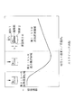
- the horizontal axis of FIG. 4 is a viscosity eta ⁇ velocity v / load F N, if the viscosity and the load is constant, the speed. If the viscosity and load are constant, the mixed lubrication region “second: h (gap) ⁇ R (surface roughness)” in the medium speed region and the fluid lubrication region “first 1: h (gap) in the high speed region. ) >> R (surface roughness) ”, the friction coefficient is small, but in the boundary lubrication region“ 3: h (gap) ⁇ 0 ”at the time of start-up, the friction coefficient becomes extremely large.
- the relationship between the groove depth applied to the sliding surface and the friction coefficient of the sliding surface is as shown in FIG.
- the relationship between the groove depth and the friction coefficient of the sliding surface varies depending on the sliding speed.
- the dynamic pressure generating groove applied to the mechanical seal is designed so as to be effective in the normal rotational speed range and sufficiently introduce the fluid into the sliding surface.
- the machining was performed by machining, blasting, and laser, and the groove depth was several ⁇ m or more. Therefore, although the friction is low in the medium speed range and the high speed range, the load capacity cannot be obtained in the low speed range, and it is difficult to realize the low friction.
- sufficient dynamic pressure cannot be generated at the time of starting or stopping, sufficient lubrication characteristics cannot be exhibited, and there is a problem that squealing or excessive contact of the sliding surface occurs at the time of starting or stopping.
- Patent Documents 1 and 2 are intended to generate dynamic pressure between the sliding surfaces by relative rotation with the mating sliding material on the sliding surface.
- the friction is low in the high and low speed ranges, there is a problem that sufficient lubrication characteristics cannot be exhibited because a sufficient dynamic pressure cannot be generated at the low and middle or high speed ranges or at the start or stop.
- an annular groove for preventing leakage is provided on the low pressure side of the sliding surface in order to reduce the amount of leakage. There was a need.
- the present invention provides a sliding component that can significantly improve the lubrication characteristics at the time of start or stop while reducing the amount of leakage of the sealed fluid, and can be operated by fluid lubrication at the time of rotation to achieve both sealing and lubrication. It is intended to do.
- the sliding component of the present invention firstly has a submicron step substantially parallel to the sliding surface on one sliding surface of the pair of sliding components that slide relative to each other.
- a plurality of positive pressure generating mechanisms comprising ultra-shallow parallel grooves having a plurality of are provided independently in the circumferential direction, and the ultra-shallow parallel grooves communicate with the high-pressure fluid side and are separated from the low-pressure fluid side by a sealing surface.
- the ultra-shallow parallel groove has an ultra-shallow thin groove formed at the bottom thereof. According to the first feature, the sealed fluid entering the ultra-shallow parallel grooves forms an extremely thin fluid film, and the pressure of the fluid that can be sealed without increasing leakage is increased by the action of surface tension.
- the sliding surface can be lifted to the minimum necessary by the dynamic pressure effect, so it is good without increasing leakage.
- Lubrication performance can be maintained, and in particular, the lubrication characteristics at the time of starting or stopping can be remarkably improved.
- the flow of fluid in the ultra-shallow parallel groove can be controlled, for example, in the ultra-shallow parallel groove according to the width of the seal surface formed between the ultra-shallow parallel groove and the inner periphery of the seal surface.
- the ultra-shallow parallel groove has a groove depth h of 10 nm to 1 ⁇ m
- the ultra-shallow thin groove has a groove depth a of 10 nm. It is characterized in that it is ⁇ 1 ⁇ m and the pitch p is 1 to 500 ⁇ m.
- the sliding component of the present invention is characterized in that, in the second feature, the depth h of the ultra-shallow parallel groove is preferably 50 to 500 nm. According to the second and third features, the lubrication characteristics at the time of starting or stopping can be remarkably improved without further increasing leakage.
- the ultra shallow groove forms a predetermined angle with respect to the sliding direction of the sliding surface. It is formed so that it may incline.
- the fluid can be taken into the ultra-shallow parallel groove or rectified so as to discharge the fluid in the ultra-shallow parallel groove.
- the lubrication characteristics at the time of starting or stopping can be remarkably improved without further increasing leakage.
- the direction of the adjacent ultra shallow groove is symmetric with respect to the sliding direction of the sliding surface. It is characterized by being formed as follows.
- the fluid in the adjacent ultra-shallow parallel grooves is alternately rectified to the high-pressure fluid side or the low-pressure fluid side, which is advantageous when the sliding component rotates in both directions.
- the sliding component according to any one of the first to third features is characterized in that the extremely shallow narrow groove is formed along a radial direction.
- the fluid in the ultra-shallow parallel groove is rectified in the radial direction so that the fluid can easily flow into the ultra-shallow parallel groove even when the sliding component is started or stopped. Lubrication characteristics when stopped can be improved. From the viewpoint of preventing leakage, it is suitable when the width of the seal surface formed between the ultra-shallow parallel groove and the inner periphery of the seal surface is wide.
- the sliding component of the present invention is seventhly characterized in that, in any of the first to third features, the ultra-shallow thin groove is formed along a circumferential direction.
- the fluid in the ultra-shallow parallel groove is rectified so as to go in the circumferential direction, and the sliding surface S positioned between the ultra-shallow parallel grooves is activated when the sliding component is started or stopped and rotated.
- the fluid is more easily supplied, and the lubrication characteristics are further improved.
- the present invention is also applicable when the width of the seal surface formed between the ultra-shallow parallel groove and the inner periphery of the seal surface is narrow.
- the ultra-shallow parallel groove is preferably in the range of 5 to 70% with respect to the area of the sliding surface. It is characterized by being provided by. According to the eighth feature, it is possible to keep the surface pressure of the sliding surface in a good state, reduce leakage, and remarkably improve the lubrication characteristics at the time of starting or stopping.
- the sliding component according to the present invention is characterized in that, in any one of the first to eighth features, the stationary sliding member or the rotating sliding member of the mechanical seal in which the pair of sliding components rotate relative to each other. It is characterized by comprising an annular body that is used as According to the ninth feature, it is possible to obtain a mechanical seal capable of maintaining good lubrication performance without increasing leakage, and particularly capable of remarkably improving the lubrication characteristics at the time of starting or stopping.
- the flow of fluid in the ultra-shallow parallel groove can be controlled, for example, in the ultra-shallow parallel groove according to the width of the seal surface formed between the ultra-shallow parallel groove and the inner periphery of the seal surface. By rectifying the fluid flow in the optimum direction, it is possible to provide a mechanical seal capable of obtaining a degree of freedom in design that can achieve both improvement of sliding surface lubrication characteristics and reduction of leakage.
- a positive pressure generating mechanism comprising ultra-shallow parallel grooves having a submicron step substantially parallel to the sliding surface is provided in the circumferential direction on one sliding surface of the pair of sliding parts that slide relative to each other.
- a plurality of independent shallow grooves are connected to the high-pressure fluid side, separated from the low-pressure fluid side by a sealing surface, and an ultra-shallow thin groove is formed at the bottom of the ultra-shallow parallel groove.
- the sliding surface When rotating, dynamic pressure is generated by sliding relative to the mating sliding surface, and the sliding surface can be lifted to the minimum necessary level due to the dynamic pressure effect, so good lubrication performance without increasing leakage In particular, the lubrication characteristics during start-up and stop are significantly improved. It can be.
- the flow of fluid in the ultra-shallow parallel groove can be controlled, for example, in the ultra-shallow parallel groove according to the width of the seal surface formed between the ultra-shallow parallel groove and the inner periphery of the seal surface. By rectifying the fluid flow in the optimum direction, it is possible to obtain a degree of design freedom that can achieve both improvement in sliding surface lubrication characteristics and reduction in leakage.
- the ultra-shallow narrow groove is formed so as to incline at a predetermined angle with respect to the sliding direction of the sliding surface, so that fluid can be taken into the ultra-shallow parallel groove or The flow can be rectified so as to discharge the fluid in the parallel groove.
- the inclination direction or angle is set according to the width of the seal surface formed between the ultra-shallow parallel groove and the inner periphery of the seal surface.
- the ultra-shallow narrow groove is formed so that the direction of the adjacent ultra-shallow groove is symmetric with respect to the sliding direction of the sliding surface, so that the fluid in the adjacent ultra-shallow parallel groove is Since the flow is alternately rectified to the high-pressure fluid side or the low-pressure fluid side, it is convenient when the sliding component rotates in both directions.
- the ultra-shallow narrow groove is formed along the radial direction, the fluid in the ultra-shallow parallel groove is rectified so as to be directed in the radial direction. Lubrication characteristics when starting or stopping moving parts can be improved. From the viewpoint of preventing leakage, it is suitable when the seal surface formed between the ultra-shallow parallel groove and the inner periphery of the seal surface is wide. In addition, since the ultra-shallow narrow groove is formed along the circumferential direction, when the sliding component is started or stopped and rotated, fluid is more applied to the sliding surface S located between the ultra-shallow parallel grooves. It becomes easy to be supplied and the lubrication characteristics are further improved. From the viewpoint of preventing leakage, it is suitable when the width of the seal surface formed between the ultra-shallow parallel groove and the inner periphery of the seal surface is narrow.
- the ultra-shallow parallel grooves are preferably provided in a range of 5 to 70% of the sliding surface area, so that the surface pressure of the sliding surface is kept in a good state and leakage is reduced.
- the lubrication characteristics at the start or stop can be remarkably improved.
- a pair of sliding parts is composed of an annular body used as a stationary sliding member or rotating sliding member of a mechanical seal that rotates relative to each other, thereby maintaining good lubrication performance without increasing leakage.
- the flow of fluid in the ultra-shallow parallel groove can be controlled, for example, in the ultra-shallow parallel groove according to the width of the seal surface formed between the ultra-shallow parallel groove and the inner periphery of the seal surface.
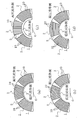
- FIG. 4 is a cross-sectional view taken along the line BB. It is a figure explaining a dynamic pressure effect, Comprising: (a) In the case of this invention, (b) shows the case of a prior art. It shows the direction of the ultra-shallow parallel groove formed at the bottom of the ultra-shallow parallel groove, and (a) is inclined in the same direction at a predetermined angle with respect to the sliding direction of the sliding surface.
- (B) shows a case where the direction of adjacent ultra-shallow narrow grooves is formed so as to be symmetric with respect to the sliding direction of the sliding surface, and (c) shows that it is formed along the radial direction.
- (D) shows the case where it forms along the circumferential direction. It is a figure explaining the friction characteristic of a bearing, A horizontal axis shows bearing characteristic number G (dimensionless), and a vertical axis shows friction coefficient f. In the mechanical seal, the relationship between the depth of the groove formed on the sliding surface and the friction coefficient of the sliding surface is obtained according to the sliding speed of the sliding surface.
- the sliding component 1 forms an annular body, and usually a high-pressure sealed fluid exists on one side of the inner and outer circumferences of the sliding surface S of the sliding component 1, The other side is the atmosphere.
- the sealed fluid can be effectively sealed using the sliding component 1.
- the sliding component 1 is used in any one of a pair of rotation sealing rings and fixing sealing rings in a mechanical seal device. The sliding surface of the sealing ring for rotation and the sliding surface of the sealing ring for fixing opposite thereto are brought into close contact with each other to seal the sealed fluid existing on either the inner or outer periphery of the sliding surface.
- the cross-sectional shape of the sliding component 1 is a convex shape as shown in FIG. 1 (c), and the top surface constitutes the sliding surface S.
- a positive pressure generating mechanism comprising an ultra-shallow parallel groove 2 having a submicron step substantially parallel to the sliding surface S as shown in FIG. A plurality are provided.
- the ultra-shallow parallel groove 2 is provided near the high-pressure fluid side rather than the entire radial width of the sliding surface S, communicates with the high-pressure fluid side, and is separated from the low-pressure fluid side by the seal surface 3. .
- the sealing surface 3 has good lubrication characteristics when the radial width is narrow, but is liable to leak. If the radial width is wide, the sealing surface 3 is difficult to leak, but the lubrication characteristics deteriorate.
- an ultra-shallow thin groove 10 is formed at the bottom of the ultra-shallow parallel groove 2.
- the ultra-shallow thin groove 10 is for controlling the flow of fluid in the ultra-shallow parallel groove 2, and is formed toward a certain direction.
- the cross-sectional shape of the ultra-shallow thin groove 10 is shown in FIG. 1B as a substantially square groove shape, but is not limited thereto, and may be, for example, a corrugated shape or a saw blade shape. .
- the bottom of the ultra-shallow parallel groove 2 before the ultra-shallow thin groove 10 is formed is formed with irregularities whose surface roughness is about 1/10 of the depth of the ultra-shallow parallel groove 2.
- the ultra-shallow thin groove 10 is formed in the depth direction from the smooth bottom.
- the ultra-shallow parallel grooves 2 have a groove depth h in the range of 10 nm to 1 ⁇ m, preferably in the range of 50 to 500 nm.
- the ultra-shallow thin groove 10 has a groove depth a of 10 nm to 1 ⁇ m and a pitch p of 1 to 500 ⁇ m. Further, the groove width b of the ultra-shallow thin groove 10 is equal to or less than the pitch p.
- the ultra-shallow parallel grooves 2 constituting the positive pressure generating mechanism are extremely shallow with a groove depth h in the range of 10 nm to 1 ⁇ m, and an ultra-shallow thin groove 10 is formed at the bottom thereof, so that the ultra-shallow parallel grooves 2 are formed. Since there is no protrusion in the groove 2, the sealed fluid that enters the ultra-shallow parallel groove 2 forms an extremely thin fluid film, and the pressure that can seal the fluid without increasing leakage due to the action of surface tension The area can be increased. During rotation, dynamic pressure is generated by relative sliding with the mating sliding surface, and the sliding surface can be lifted by the dynamic pressure effect.
- the ultra-shallow parallel groove 2 is ultra-shallow, and an ultra-shallow thin groove 10 is formed at the bottom thereof and protrudes into the ultra-shallow parallel groove 2. Therefore, the pressure distribution of the dynamic pressure generated by the relative sliding with the mating sliding surface becomes large.
- the dynamic pressure generating groove is formed by the same height as the depth of the groove. The pressure distribution of the dynamic pressure generated by the relative sliding is smaller than in the case of the present invention.
- the ultra-shallow parallel groove 2 is extremely shallow, so that there is little leakage at the time of starting or stopping, and the ultra-shallow thin groove 10 is formed at the bottom despite being extremely shallow. Since there is no protrusion formed in the ultra-shallow parallel groove 2, a lubricating effect can be exhibited during rotation.
- the ultra-shallow parallel grooves 2 are preferably provided in the range of 5 to 70% with respect to the area of the sliding surface S.
- the ultra-shallow parallel grooves 2 are arranged at 16 equal intervals in the circumferential direction.
- the sliding surface S itself is set to such a surface roughness that the ultra-shallow parallel grooves 2 become clear by mirror finishing.
- the ultra-shallow narrow groove 10 is for controlling the flow of fluid in the ultra-shallow parallel groove 2, and by setting the direction of the ultra-shallow thin groove to a desired direction, fluid in the ultra-shallow parallel groove 2 is obtained.
- the fluid can be easily discharged from the ultra-shallow parallel groove 2, or the fluid can be easily supplied to the sliding surface S.
- the ultra-shallow thin groove 10 formed at the bottom of the ultra-shallow parallel groove 2 controls the flow of fluid in the ultra-shallow parallel groove 2 and is formed, for example, between the ultra-shallow parallel groove and the inner periphery of the seal surface.
- the flow of fluid in the ultra-shallow parallel groove is rectified in an optimal direction according to the width of the seal surface to be improved, improving the sliding surface lubrication characteristics and reducing leakage that were difficult with the ultra-shallow parallel groove 2 alone. It is possible to give a design freedom that can be compatible.
- Such ultra-shallow parallel grooves 2 and ultra-shallow thin grooves 10 at the bottom thereof are processed by, for example, etching.
- the present invention is not limited to etching, and any other processing method may be used as long as the groove depth h is in the range of 10 nm to 1 ⁇ m and an extremely shallow thin groove can be processed at the bottom.
- the ultra-shallow narrow groove 10 is for controlling the flow of fluid in the ultra-shallow parallel groove 2, and is formed toward a certain direction.
- the ultra-shallow thin groove 10 in each ultra-shallow parallel groove 2 is a predetermined angle with respect to the sliding direction of the sliding surface, for example, each ultra-shallow parallel from the center O of the sliding component 1. It is formed so as to incline at an angle of 45 degrees with respect to the center line passing through the center of the groove 2, and all the ultra-shallow thin grooves 10 are formed in the same direction.
- the ultra-shallow thin grooves 10 in each ultra-shallow parallel groove 2 are formed such that the direction in which the adjacent ultra-shallow thin grooves incline is symmetric with respect to the sliding direction of the sliding surface. ing. For this reason, the fluid in the adjacent ultra-shallow parallel grooves 2 is alternately rectified to the high-pressure fluid side or the low-pressure fluid side. Therefore, it is convenient when the sliding part rotates in both directions.
- the ultra-shallow thin grooves 10 in each ultra-shallow parallel groove 2 are arranged in a radial direction (a direction parallel to a center line passing from the center O of the sliding part 1 to the center of each ultra-shallow parallel groove 2 ( Therefore, the fluid in the ultra-shallow parallel grooves 2 is rectified in the radial direction, so that the sliding part is started or stopped. Even in such a case, the fluid can easily flow into the ultra-shallow parallel groove 2 and improve the lubrication characteristics when starting or stopping the sliding component. This is suitable when the width of the sealing surface 3 formed between the circumference and the circumference is wide.
- the ultra-shallow thin grooves 10 in each ultra-shallow parallel groove 2 are arranged in a circumferential direction (a direction orthogonal to a center line passing from the center O of the sliding component 1 to the center of each ultra-shallow parallel groove 2 ( Therefore, the fluid in the ultra-shallow parallel grooves 2 is rectified so as to go in the circumferential direction.
- the fluid is more easily supplied to the sliding surface S located between the ultra-shallow parallel grooves 2 and the lubrication characteristics are further improved. This is suitable when the width of the sealing surface 3 formed between the circumference and the circumference is narrow.
- the actions and effects of the sliding component according to the embodiment of the present invention are as follows.
- the ultra-shallow parallel groove 2 constituting the positive pressure generating mechanism is ultra-shallow, and the ultra-shallow thin groove 10 is formed at the bottom of the ultra-shallow parallel groove 2.
- the sealed fluid that enters the parallel groove 2 forms an extremely thin fluid film, and the pressure range in which the fluid can be sealed without increasing leakage can be increased by the action of surface tension.
- dynamic pressure is generated by relative sliding with the mating sliding surface, and the sliding surface is floated to the minimum necessary by the dynamic pressure effect.
- the ultra-shallow thin groove 10 is formed at the bottom of the ultra-shallow parallel groove 2
- the flow of fluid in the ultra-shallow parallel groove 2 can be controlled.
- the ultra-shallow parallel groove and the seal surface By rectifying the flow of fluid in the ultra-shallow parallel groove in the optimal direction according to the width of the seal surface formed between the inner periphery and the inner periphery, it is possible to achieve both improved sliding surface lubrication characteristics and reduced leakage. Design freedom can be obtained.
- the ultra-shallow parallel groove 2 has a groove depth h in the range of 10 nm to 1 ⁇ m, preferably 50 to 500 nm.
- the ultra-shallow thin groove 10 has a groove depth a of 10 nm to 1 ⁇ m, Since the pitch p is set in the range of 1 to 500 ⁇ m, the lubrication characteristics at the start or stop can be remarkably improved without further increasing the leakage.
- the ultra-shallow thin groove 10 in each ultra-shallow parallel groove 2 has a predetermined angle with respect to the sliding direction of the sliding surface, for example, the center of each ultra-shallow parallel groove 2 from the center O of the sliding component 1. It is formed so as to incline at an angle of 45 degrees with respect to the passing center line, and all the ultra-shallow thin grooves 10 are formed in the same direction, so that the fluid in the ultra-shallow parallel grooves 2 is transferred to the high-pressure fluid side. Even when the width of the seal surface formed between the ultra-shallow parallel groove and the inner periphery of the seal surface is narrow, even when starting or stopping without further increasing leakage It is possible to remarkably improve the lubrication characteristics.
- the ultra-shallow grooves 10 in each ultra-shallow parallel groove 2 are formed so that the direction in which the adjacent ultra-shallow grooves are inclined is symmetric with respect to the sliding direction of the sliding surface. Since the fluid in the ultra-shallow parallel groove 2 is alternately rectified to the high pressure fluid side or the low pressure fluid side, it is convenient when the sliding component rotates in both directions.
- the ultra-shallow thin groove 10 in each ultra-shallow parallel groove 2 is formed along the radial direction, the fluid in the ultra-shallow parallel groove is rectified in the radial direction, and the sliding parts are activated.
- the fluid can easily flow into the ultra-shallow parallel groove even when stopped, and the lubrication characteristics when starting or stopping the sliding component can be improved. From the viewpoint of preventing leakage, it is suitable when the seal surface formed between the ultra-shallow parallel groove and the inner periphery of the seal surface is wide.
- the ultra-shallow thin grooves 10 in each ultra-shallow parallel groove 2 are formed along the circumferential direction, the fluid in the ultra-shallow parallel groove 2 is rectified so as to go in the circumferential direction, and the sliding parts When starting or stopping and during rotation, fluid is more easily supplied to the sliding surface S positioned between the ultra-shallow parallel grooves 2, and the lubrication characteristics are further improved. From the viewpoint of preventing leakage, it is suitable when the width of the seal surface formed between the ultra-shallow parallel groove and the inner periphery of the seal surface is narrow.
- the sliding component is used as one of the pair of rotation sealing rings and the fixing sealing ring in the mechanical seal device has been described, but lubrication is performed on one axial side of the cylindrical sliding surface. It can also be used as a sliding part of a bearing that slides on a rotating shaft while sealing oil.
- the present invention can also be applied to a case where the inner peripheral side is a high-pressure fluid. It is only necessary to communicate with each other.
Landscapes
- Engineering & Computer Science (AREA)
- General Engineering & Computer Science (AREA)
- Mechanical Engineering (AREA)
- Mechanical Sealing (AREA)
- Sliding-Contact Bearings (AREA)
- Sealing Devices (AREA)
Abstract
Priority Applications (4)
| Application Number | Priority Date | Filing Date | Title |
|---|---|---|---|
| US14/385,925 US9234594B2 (en) | 2012-05-21 | 2013-05-15 | Sliding component |
| JP2014516765A JP5995967B2 (ja) | 2012-05-21 | 2013-05-15 | 摺動部品 |
| EP13793548.2A EP2853787B1 (fr) | 2012-05-21 | 2013-05-15 | Composant coulissant |
| CN201380013961.XA CN104185756B (zh) | 2012-05-21 | 2013-05-15 | 滑动部件 |
Applications Claiming Priority (2)
| Application Number | Priority Date | Filing Date | Title |
|---|---|---|---|
| JP2012116038 | 2012-05-21 | ||
| JP2012-116038 | 2012-05-21 |
Publications (1)
| Publication Number | Publication Date |
|---|---|
| WO2013176010A1 true WO2013176010A1 (fr) | 2013-11-28 |
Family
ID=49623704
Family Applications (1)
| Application Number | Title | Priority Date | Filing Date |
|---|---|---|---|
| PCT/JP2013/063499 WO2013176010A1 (fr) | 2012-05-21 | 2013-05-15 | Composant coulissant |
Country Status (5)
| Country | Link |
|---|---|
| US (1) | US9234594B2 (fr) |
| EP (1) | EP2853787B1 (fr) |
| JP (1) | JP5995967B2 (fr) |
| CN (1) | CN104185756B (fr) |
| WO (1) | WO2013176010A1 (fr) |
Cited By (2)
| Publication number | Priority date | Publication date | Assignee | Title |
|---|---|---|---|---|
| JP2019148307A (ja) * | 2018-02-28 | 2019-09-05 | 大同メタル工業株式会社 | 半割スラスト軸受 |
| WO2023190506A1 (fr) * | 2022-03-30 | 2023-10-05 | イーグル工業株式会社 | Composant coulissant |
Families Citing this family (10)
| Publication number | Priority date | Publication date | Assignee | Title |
|---|---|---|---|---|
| EP2549155B1 (fr) * | 2010-03-15 | 2016-08-10 | Eagle Industry Co., Ltd. | Elément coulissant |
| JP6279474B2 (ja) * | 2012-09-11 | 2018-02-14 | イーグル工業株式会社 | 摺動部品 |
| US10612666B2 (en) | 2012-09-11 | 2020-04-07 | Eagle Industry Co., Ltd. | Sliding component |
| CN104379975B (zh) * | 2012-10-18 | 2017-05-31 | 伊格尔工业股份有限公司 | 滑动部件 |
| FR3009124A1 (fr) * | 2013-07-24 | 2015-01-30 | Areva Np | Glace pour garniture d'etancheite pour systeme d'etancheite d'arbre |
| WO2015031474A1 (fr) * | 2013-08-27 | 2015-03-05 | Eaton Corporation | Composite pour bague d'étanchéité permettant une meilleure étanchéité hydrodynamique |
| US11125334B2 (en) | 2016-12-21 | 2021-09-21 | Eaton Intelligent Power Limited | Hydrodynamic sealing component and assembly |
| US11248706B2 (en) * | 2017-07-07 | 2022-02-15 | Eagle Industry Co., Ltd. | Sliding member |
| CN107269847B (zh) * | 2017-07-11 | 2019-10-11 | 浙江工业大学 | 龟背状织构形状的仿贝壳型槽液体润滑机械密封结构 |
| CN110848390A (zh) * | 2019-10-28 | 2020-02-28 | 江苏大学 | 一种局部圆弧织构化机械密封 |
Citations (4)
| Publication number | Priority date | Publication date | Assignee | Title |
|---|---|---|---|---|
| JPH07260009A (ja) * | 1994-03-22 | 1995-10-13 | Nippon Pillar Packing Co Ltd | 非接触形軸封装置 |
| JP2009014183A (ja) * | 2007-07-09 | 2009-01-22 | Canon Machinery Inc | 摺動面構造 |
| JP2009087995A (ja) | 2007-09-27 | 2009-04-23 | Hitachi Via Mechanics Ltd | マスクレス露光装置 |
| JP2011196429A (ja) | 2010-03-18 | 2011-10-06 | Eagle Industry Co Ltd | メカニカルシールの摺動材及びメカニカルシール |
Family Cites Families (17)
| Publication number | Priority date | Publication date | Assignee | Title |
|---|---|---|---|---|
| US4973068A (en) * | 1988-03-15 | 1990-11-27 | University Of New Mexico | Differential surface roughness dynamic seals and bearings |
| JPH0660691B2 (ja) * | 1990-04-17 | 1994-08-10 | イーグル工業株式会社 | 両回転式準接触メカニカルシール及びリング摺動面の溝加工方法 |
| GB9214282D0 (en) * | 1992-07-04 | 1992-08-19 | Crane John Uk Ltd | Seals |
| US5501470A (en) * | 1992-12-11 | 1996-03-26 | Nippon Pillar Packing Co., Ltd. | Non-contacting shaft sealing device with grooved face pattern |
| DE19722870C2 (de) * | 1996-12-06 | 2000-09-07 | Karl Uth | Gasgeschmierte Gleitringdichtung |
| CN2460801Y (zh) * | 2001-01-18 | 2001-11-21 | 王玉明 | 可双向旋转的螺旋槽端面密封装置 |
| CN100427816C (zh) * | 2002-09-20 | 2008-10-22 | 徐万福 | 一种由角形微槽族组成的螺旋槽端面机械密封 |
| JP5278970B2 (ja) * | 2008-01-11 | 2013-09-04 | イーグル工業株式会社 | メカニカルシール摺動材及びメカニカルシール |
| CN102483162A (zh) * | 2010-02-26 | 2012-05-30 | Nok株式会社 | 密封环 |
| EP2549155B1 (fr) * | 2010-03-15 | 2016-08-10 | Eagle Industry Co., Ltd. | Elément coulissant |
| KR101513278B1 (ko) * | 2011-08-05 | 2015-04-17 | 이구루코교 가부시기가이샤 | 메커니컬 실 |
| JP5871289B2 (ja) * | 2011-09-03 | 2016-03-01 | イーグル工業株式会社 | 摺動部品 |
| US9447884B2 (en) * | 2011-09-03 | 2016-09-20 | Eagle Industry Co., Ltd. | Sliding parts |
| US9371912B2 (en) * | 2011-09-10 | 2016-06-21 | Eagle Industry Co., Ltd. | Sliding parts |
| CN103765060B (zh) * | 2011-09-10 | 2017-02-15 | 伊格尔工业股份有限公司 | 滑动部件 |
| DE202012100316U1 (de) * | 2012-01-31 | 2012-03-05 | Chetra Gmbh Dichtungstechnik | Gasgeschmierte Gleitringdichtung |
| WO2013176009A1 (fr) * | 2012-05-21 | 2013-11-28 | イーグル工業株式会社 | Composant coulissant |
-
2013
- 2013-05-15 EP EP13793548.2A patent/EP2853787B1/fr active Active
- 2013-05-15 JP JP2014516765A patent/JP5995967B2/ja active Active
- 2013-05-15 CN CN201380013961.XA patent/CN104185756B/zh active Active
- 2013-05-15 WO PCT/JP2013/063499 patent/WO2013176010A1/fr active Application Filing
- 2013-05-15 US US14/385,925 patent/US9234594B2/en active Active
Patent Citations (4)
| Publication number | Priority date | Publication date | Assignee | Title |
|---|---|---|---|---|
| JPH07260009A (ja) * | 1994-03-22 | 1995-10-13 | Nippon Pillar Packing Co Ltd | 非接触形軸封装置 |
| JP2009014183A (ja) * | 2007-07-09 | 2009-01-22 | Canon Machinery Inc | 摺動面構造 |
| JP2009087995A (ja) | 2007-09-27 | 2009-04-23 | Hitachi Via Mechanics Ltd | マスクレス露光装置 |
| JP2011196429A (ja) | 2010-03-18 | 2011-10-06 | Eagle Industry Co Ltd | メカニカルシールの摺動材及びメカニカルシール |
Cited By (2)
| Publication number | Priority date | Publication date | Assignee | Title |
|---|---|---|---|---|
| JP2019148307A (ja) * | 2018-02-28 | 2019-09-05 | 大同メタル工業株式会社 | 半割スラスト軸受 |
| WO2023190506A1 (fr) * | 2022-03-30 | 2023-10-05 | イーグル工業株式会社 | Composant coulissant |
Also Published As
| Publication number | Publication date |
|---|---|
| CN104185756A (zh) | 2014-12-03 |
| EP2853787A4 (fr) | 2016-03-09 |
| JPWO2013176010A1 (ja) | 2016-01-12 |
| US20150042045A1 (en) | 2015-02-12 |
| US9234594B2 (en) | 2016-01-12 |
| EP2853787A1 (fr) | 2015-04-01 |
| CN104185756B (zh) | 2016-10-26 |
| JP5995967B2 (ja) | 2016-09-21 |
| EP2853787B1 (fr) | 2019-05-08 |
Similar Documents
| Publication | Publication Date | Title |
|---|---|---|
| JP6080845B2 (ja) | 摺動部品 | |
| JP5995967B2 (ja) | 摺動部品 | |
| JP6076971B2 (ja) | 摺動部品 | |
| JP6861730B2 (ja) | しゅう動部品 | |
| JP7179430B2 (ja) | 摺動部品 | |
| JP5881716B2 (ja) | 摺動部品 | |
| US10132411B2 (en) | Sliding component | |
| JP2022097663A (ja) | 摺動部品 | |
| US11248706B2 (en) | Sliding member | |
| US9677670B2 (en) | Sliding parts | |
| JP6279474B2 (ja) | 摺動部品 | |
| WO2020166589A1 (fr) | Composants coulissants | |
| WO2014061544A1 (fr) | Partie coulissante | |
| JPWO2019221226A1 (ja) | シールリング | |
| JP6138132B2 (ja) | 摺動部品 | |
| JPWO2019221227A1 (ja) | シールリング | |
| JPH0611046A (ja) | シーリング装置 | |
| JPWO2020171102A1 (ja) | 摺動部品 | |
| WO2022190944A1 (fr) | Élément coulissant | |
| WO2020218286A1 (fr) | Élément coulissant |
Legal Events
| Date | Code | Title | Description |
|---|---|---|---|
| 121 | Ep: the epo has been informed by wipo that ep was designated in this application |
Ref document number: 13793548 Country of ref document: EP Kind code of ref document: A1 |
|
| ENP | Entry into the national phase |
Ref document number: 2014516765 Country of ref document: JP Kind code of ref document: A |
|
| WWE | Wipo information: entry into national phase |
Ref document number: 14385925 Country of ref document: US Ref document number: 2013793548 Country of ref document: EP |
|
| NENP | Non-entry into the national phase |
Ref country code: DE |