WO2013175572A1 - Dispositif de purification d'émission d'échappement pour moteur à combustion interne - Google Patents
Dispositif de purification d'émission d'échappement pour moteur à combustion interne Download PDFInfo
- Publication number
- WO2013175572A1 WO2013175572A1 PCT/JP2012/063050 JP2012063050W WO2013175572A1 WO 2013175572 A1 WO2013175572 A1 WO 2013175572A1 JP 2012063050 W JP2012063050 W JP 2012063050W WO 2013175572 A1 WO2013175572 A1 WO 2013175572A1
- Authority
- WO
- WIPO (PCT)
- Prior art keywords
- filter
- amount
- nox catalyst
- sensor
- failure
- Prior art date
Links
Images


Classifications
-
- F—MECHANICAL ENGINEERING; LIGHTING; HEATING; WEAPONS; BLASTING
- F01—MACHINES OR ENGINES IN GENERAL; ENGINE PLANTS IN GENERAL; STEAM ENGINES
- F01N—GAS-FLOW SILENCERS OR EXHAUST APPARATUS FOR MACHINES OR ENGINES IN GENERAL; GAS-FLOW SILENCERS OR EXHAUST APPARATUS FOR INTERNAL COMBUSTION ENGINES
- F01N3/00—Exhaust or silencing apparatus having means for purifying, rendering innocuous, or otherwise treating exhaust
- F01N3/08—Exhaust or silencing apparatus having means for purifying, rendering innocuous, or otherwise treating exhaust for rendering innocuous
- F01N3/10—Exhaust or silencing apparatus having means for purifying, rendering innocuous, or otherwise treating exhaust for rendering innocuous by thermal or catalytic conversion of noxious components of exhaust
- F01N3/18—Exhaust or silencing apparatus having means for purifying, rendering innocuous, or otherwise treating exhaust for rendering innocuous by thermal or catalytic conversion of noxious components of exhaust characterised by methods of operation; Control
- F01N3/20—Exhaust or silencing apparatus having means for purifying, rendering innocuous, or otherwise treating exhaust for rendering innocuous by thermal or catalytic conversion of noxious components of exhaust characterised by methods of operation; Control specially adapted for catalytic conversion ; Methods of operation or control of catalytic converters
- F01N3/2066—Selective catalytic reduction [SCR]
- F01N3/208—Control of selective catalytic reduction [SCR], e.g. dosing of reducing agent
-
- B—PERFORMING OPERATIONS; TRANSPORTING
- B01—PHYSICAL OR CHEMICAL PROCESSES OR APPARATUS IN GENERAL
- B01D—SEPARATION
- B01D53/00—Separation of gases or vapours; Recovering vapours of volatile solvents from gases; Chemical or biological purification of waste gases, e.g. engine exhaust gases, smoke, fumes, flue gases, aerosols
- B01D53/34—Chemical or biological purification of waste gases
- B01D53/92—Chemical or biological purification of waste gases of engine exhaust gases
- B01D53/94—Chemical or biological purification of waste gases of engine exhaust gases by catalytic processes
- B01D53/9495—Controlling the catalytic process
-
- B—PERFORMING OPERATIONS; TRANSPORTING
- B01—PHYSICAL OR CHEMICAL PROCESSES OR APPARATUS IN GENERAL
- B01D—SEPARATION
- B01D53/00—Separation of gases or vapours; Recovering vapours of volatile solvents from gases; Chemical or biological purification of waste gases, e.g. engine exhaust gases, smoke, fumes, flue gases, aerosols
- B01D53/34—Chemical or biological purification of waste gases
- B01D53/92—Chemical or biological purification of waste gases of engine exhaust gases
- B01D53/94—Chemical or biological purification of waste gases of engine exhaust gases by catalytic processes
- B01D53/9404—Removing only nitrogen compounds
- B01D53/9409—Nitrogen oxides
- B01D53/9413—Processes characterised by a specific catalyst
- B01D53/9418—Processes characterised by a specific catalyst for removing nitrogen oxides by selective catalytic reduction [SCR] using a reducing agent in a lean exhaust gas
-
- B—PERFORMING OPERATIONS; TRANSPORTING
- B01—PHYSICAL OR CHEMICAL PROCESSES OR APPARATUS IN GENERAL
- B01D—SEPARATION
- B01D53/00—Separation of gases or vapours; Recovering vapours of volatile solvents from gases; Chemical or biological purification of waste gases, e.g. engine exhaust gases, smoke, fumes, flue gases, aerosols
- B01D53/34—Chemical or biological purification of waste gases
- B01D53/92—Chemical or biological purification of waste gases of engine exhaust gases
- B01D53/94—Chemical or biological purification of waste gases of engine exhaust gases by catalytic processes
- B01D53/9404—Removing only nitrogen compounds
- B01D53/9409—Nitrogen oxides
- B01D53/9431—Processes characterised by a specific device
-
- F—MECHANICAL ENGINEERING; LIGHTING; HEATING; WEAPONS; BLASTING
- F01—MACHINES OR ENGINES IN GENERAL; ENGINE PLANTS IN GENERAL; STEAM ENGINES
- F01N—GAS-FLOW SILENCERS OR EXHAUST APPARATUS FOR MACHINES OR ENGINES IN GENERAL; GAS-FLOW SILENCERS OR EXHAUST APPARATUS FOR INTERNAL COMBUSTION ENGINES
- F01N11/00—Monitoring or diagnostic devices for exhaust-gas treatment apparatus, e.g. for catalytic activity
- F01N11/002—Monitoring or diagnostic devices for exhaust-gas treatment apparatus, e.g. for catalytic activity the diagnostic devices measuring or estimating temperature or pressure in, or downstream of the exhaust apparatus
-
- F—MECHANICAL ENGINEERING; LIGHTING; HEATING; WEAPONS; BLASTING
- F01—MACHINES OR ENGINES IN GENERAL; ENGINE PLANTS IN GENERAL; STEAM ENGINES
- F01N—GAS-FLOW SILENCERS OR EXHAUST APPARATUS FOR MACHINES OR ENGINES IN GENERAL; GAS-FLOW SILENCERS OR EXHAUST APPARATUS FOR INTERNAL COMBUSTION ENGINES
- F01N3/00—Exhaust or silencing apparatus having means for purifying, rendering innocuous, or otherwise treating exhaust
- F01N3/02—Exhaust or silencing apparatus having means for purifying, rendering innocuous, or otherwise treating exhaust for cooling, or for removing solid constituents of, exhaust
- F01N3/021—Exhaust or silencing apparatus having means for purifying, rendering innocuous, or otherwise treating exhaust for cooling, or for removing solid constituents of, exhaust by means of filters
- F01N3/023—Exhaust or silencing apparatus having means for purifying, rendering innocuous, or otherwise treating exhaust for cooling, or for removing solid constituents of, exhaust by means of filters using means for regenerating the filters, e.g. by burning trapped particles
-
- F—MECHANICAL ENGINEERING; LIGHTING; HEATING; WEAPONS; BLASTING
- F01—MACHINES OR ENGINES IN GENERAL; ENGINE PLANTS IN GENERAL; STEAM ENGINES
- F01N—GAS-FLOW SILENCERS OR EXHAUST APPARATUS FOR MACHINES OR ENGINES IN GENERAL; GAS-FLOW SILENCERS OR EXHAUST APPARATUS FOR INTERNAL COMBUSTION ENGINES
- F01N3/00—Exhaust or silencing apparatus having means for purifying, rendering innocuous, or otherwise treating exhaust
- F01N3/02—Exhaust or silencing apparatus having means for purifying, rendering innocuous, or otherwise treating exhaust for cooling, or for removing solid constituents of, exhaust
- F01N3/021—Exhaust or silencing apparatus having means for purifying, rendering innocuous, or otherwise treating exhaust for cooling, or for removing solid constituents of, exhaust by means of filters
- F01N3/033—Exhaust or silencing apparatus having means for purifying, rendering innocuous, or otherwise treating exhaust for cooling, or for removing solid constituents of, exhaust by means of filters in combination with other devices
- F01N3/035—Exhaust or silencing apparatus having means for purifying, rendering innocuous, or otherwise treating exhaust for cooling, or for removing solid constituents of, exhaust by means of filters in combination with other devices with catalytic reactors, e.g. catalysed diesel particulate filters
-
- F—MECHANICAL ENGINEERING; LIGHTING; HEATING; WEAPONS; BLASTING
- F01—MACHINES OR ENGINES IN GENERAL; ENGINE PLANTS IN GENERAL; STEAM ENGINES
- F01N—GAS-FLOW SILENCERS OR EXHAUST APPARATUS FOR MACHINES OR ENGINES IN GENERAL; GAS-FLOW SILENCERS OR EXHAUST APPARATUS FOR INTERNAL COMBUSTION ENGINES
- F01N3/00—Exhaust or silencing apparatus having means for purifying, rendering innocuous, or otherwise treating exhaust
- F01N3/08—Exhaust or silencing apparatus having means for purifying, rendering innocuous, or otherwise treating exhaust for rendering innocuous
- F01N3/10—Exhaust or silencing apparatus having means for purifying, rendering innocuous, or otherwise treating exhaust for rendering innocuous by thermal or catalytic conversion of noxious components of exhaust
- F01N3/18—Exhaust or silencing apparatus having means for purifying, rendering innocuous, or otherwise treating exhaust for rendering innocuous by thermal or catalytic conversion of noxious components of exhaust characterised by methods of operation; Control
- F01N3/20—Exhaust or silencing apparatus having means for purifying, rendering innocuous, or otherwise treating exhaust for rendering innocuous by thermal or catalytic conversion of noxious components of exhaust characterised by methods of operation; Control specially adapted for catalytic conversion ; Methods of operation or control of catalytic converters
- F01N3/2066—Selective catalytic reduction [SCR]
-
- F—MECHANICAL ENGINEERING; LIGHTING; HEATING; WEAPONS; BLASTING
- F01—MACHINES OR ENGINES IN GENERAL; ENGINE PLANTS IN GENERAL; STEAM ENGINES
- F01N—GAS-FLOW SILENCERS OR EXHAUST APPARATUS FOR MACHINES OR ENGINES IN GENERAL; GAS-FLOW SILENCERS OR EXHAUST APPARATUS FOR INTERNAL COMBUSTION ENGINES
- F01N9/00—Electrical control of exhaust gas treating apparatus
- F01N9/002—Electrical control of exhaust gas treating apparatus of filter regeneration, e.g. detection of clogging
-
- F—MECHANICAL ENGINEERING; LIGHTING; HEATING; WEAPONS; BLASTING
- F01—MACHINES OR ENGINES IN GENERAL; ENGINE PLANTS IN GENERAL; STEAM ENGINES
- F01N—GAS-FLOW SILENCERS OR EXHAUST APPARATUS FOR MACHINES OR ENGINES IN GENERAL; GAS-FLOW SILENCERS OR EXHAUST APPARATUS FOR INTERNAL COMBUSTION ENGINES
- F01N2250/00—Combinations of different methods of purification
- F01N2250/02—Combinations of different methods of purification filtering and catalytic conversion
-
- F—MECHANICAL ENGINEERING; LIGHTING; HEATING; WEAPONS; BLASTING
- F01—MACHINES OR ENGINES IN GENERAL; ENGINE PLANTS IN GENERAL; STEAM ENGINES
- F01N—GAS-FLOW SILENCERS OR EXHAUST APPARATUS FOR MACHINES OR ENGINES IN GENERAL; GAS-FLOW SILENCERS OR EXHAUST APPARATUS FOR INTERNAL COMBUSTION ENGINES
- F01N2550/00—Monitoring or diagnosing the deterioration of exhaust systems
- F01N2550/02—Catalytic activity of catalytic converters
-
- F—MECHANICAL ENGINEERING; LIGHTING; HEATING; WEAPONS; BLASTING
- F01—MACHINES OR ENGINES IN GENERAL; ENGINE PLANTS IN GENERAL; STEAM ENGINES
- F01N—GAS-FLOW SILENCERS OR EXHAUST APPARATUS FOR MACHINES OR ENGINES IN GENERAL; GAS-FLOW SILENCERS OR EXHAUST APPARATUS FOR INTERNAL COMBUSTION ENGINES
- F01N2550/00—Monitoring or diagnosing the deterioration of exhaust systems
- F01N2550/04—Filtering activity of particulate filters
-
- F—MECHANICAL ENGINEERING; LIGHTING; HEATING; WEAPONS; BLASTING
- F01—MACHINES OR ENGINES IN GENERAL; ENGINE PLANTS IN GENERAL; STEAM ENGINES
- F01N—GAS-FLOW SILENCERS OR EXHAUST APPARATUS FOR MACHINES OR ENGINES IN GENERAL; GAS-FLOW SILENCERS OR EXHAUST APPARATUS FOR INTERNAL COMBUSTION ENGINES
- F01N2560/00—Exhaust systems with means for detecting or measuring exhaust gas components or characteristics
- F01N2560/02—Exhaust systems with means for detecting or measuring exhaust gas components or characteristics the means being an exhaust gas sensor
- F01N2560/026—Exhaust systems with means for detecting or measuring exhaust gas components or characteristics the means being an exhaust gas sensor for measuring or detecting NOx
-
- F—MECHANICAL ENGINEERING; LIGHTING; HEATING; WEAPONS; BLASTING
- F01—MACHINES OR ENGINES IN GENERAL; ENGINE PLANTS IN GENERAL; STEAM ENGINES
- F01N—GAS-FLOW SILENCERS OR EXHAUST APPARATUS FOR MACHINES OR ENGINES IN GENERAL; GAS-FLOW SILENCERS OR EXHAUST APPARATUS FOR INTERNAL COMBUSTION ENGINES
- F01N2560/00—Exhaust systems with means for detecting or measuring exhaust gas components or characteristics
- F01N2560/05—Exhaust systems with means for detecting or measuring exhaust gas components or characteristics the means being a particulate sensor
-
- F—MECHANICAL ENGINEERING; LIGHTING; HEATING; WEAPONS; BLASTING
- F01—MACHINES OR ENGINES IN GENERAL; ENGINE PLANTS IN GENERAL; STEAM ENGINES
- F01N—GAS-FLOW SILENCERS OR EXHAUST APPARATUS FOR MACHINES OR ENGINES IN GENERAL; GAS-FLOW SILENCERS OR EXHAUST APPARATUS FOR INTERNAL COMBUSTION ENGINES
- F01N2560/00—Exhaust systems with means for detecting or measuring exhaust gas components or characteristics
- F01N2560/06—Exhaust systems with means for detecting or measuring exhaust gas components or characteristics the means being a temperature sensor
-
- F—MECHANICAL ENGINEERING; LIGHTING; HEATING; WEAPONS; BLASTING
- F01—MACHINES OR ENGINES IN GENERAL; ENGINE PLANTS IN GENERAL; STEAM ENGINES
- F01N—GAS-FLOW SILENCERS OR EXHAUST APPARATUS FOR MACHINES OR ENGINES IN GENERAL; GAS-FLOW SILENCERS OR EXHAUST APPARATUS FOR INTERNAL COMBUSTION ENGINES
- F01N2560/00—Exhaust systems with means for detecting or measuring exhaust gas components or characteristics
- F01N2560/07—Exhaust systems with means for detecting or measuring exhaust gas components or characteristics the means being an exhaust gas flow rate or velocity meter or sensor, intake flow meters only when exclusively used to determine exhaust gas parameters
-
- F—MECHANICAL ENGINEERING; LIGHTING; HEATING; WEAPONS; BLASTING
- F01—MACHINES OR ENGINES IN GENERAL; ENGINE PLANTS IN GENERAL; STEAM ENGINES
- F01N—GAS-FLOW SILENCERS OR EXHAUST APPARATUS FOR MACHINES OR ENGINES IN GENERAL; GAS-FLOW SILENCERS OR EXHAUST APPARATUS FOR INTERNAL COMBUSTION ENGINES
- F01N2560/00—Exhaust systems with means for detecting or measuring exhaust gas components or characteristics
- F01N2560/08—Exhaust systems with means for detecting or measuring exhaust gas components or characteristics the means being a pressure sensor
-
- F—MECHANICAL ENGINEERING; LIGHTING; HEATING; WEAPONS; BLASTING
- F01—MACHINES OR ENGINES IN GENERAL; ENGINE PLANTS IN GENERAL; STEAM ENGINES
- F01N—GAS-FLOW SILENCERS OR EXHAUST APPARATUS FOR MACHINES OR ENGINES IN GENERAL; GAS-FLOW SILENCERS OR EXHAUST APPARATUS FOR INTERNAL COMBUSTION ENGINES
- F01N2560/00—Exhaust systems with means for detecting or measuring exhaust gas components or characteristics
- F01N2560/14—Exhaust systems with means for detecting or measuring exhaust gas components or characteristics having more than one sensor of one kind
-
- F—MECHANICAL ENGINEERING; LIGHTING; HEATING; WEAPONS; BLASTING
- F01—MACHINES OR ENGINES IN GENERAL; ENGINE PLANTS IN GENERAL; STEAM ENGINES
- F01N—GAS-FLOW SILENCERS OR EXHAUST APPARATUS FOR MACHINES OR ENGINES IN GENERAL; GAS-FLOW SILENCERS OR EXHAUST APPARATUS FOR INTERNAL COMBUSTION ENGINES
- F01N3/00—Exhaust or silencing apparatus having means for purifying, rendering innocuous, or otherwise treating exhaust
- F01N3/08—Exhaust or silencing apparatus having means for purifying, rendering innocuous, or otherwise treating exhaust for rendering innocuous
- F01N3/10—Exhaust or silencing apparatus having means for purifying, rendering innocuous, or otherwise treating exhaust for rendering innocuous by thermal or catalytic conversion of noxious components of exhaust
- F01N3/103—Oxidation catalysts for HC and CO only
-
- Y—GENERAL TAGGING OF NEW TECHNOLOGICAL DEVELOPMENTS; GENERAL TAGGING OF CROSS-SECTIONAL TECHNOLOGIES SPANNING OVER SEVERAL SECTIONS OF THE IPC; TECHNICAL SUBJECTS COVERED BY FORMER USPC CROSS-REFERENCE ART COLLECTIONS [XRACs] AND DIGESTS
- Y02—TECHNOLOGIES OR APPLICATIONS FOR MITIGATION OR ADAPTATION AGAINST CLIMATE CHANGE
- Y02T—CLIMATE CHANGE MITIGATION TECHNOLOGIES RELATED TO TRANSPORTATION
- Y02T10/00—Road transport of goods or passengers
- Y02T10/10—Internal combustion engine [ICE] based vehicles
- Y02T10/12—Improving ICE efficiencies
-
- Y—GENERAL TAGGING OF NEW TECHNOLOGICAL DEVELOPMENTS; GENERAL TAGGING OF CROSS-SECTIONAL TECHNOLOGIES SPANNING OVER SEVERAL SECTIONS OF THE IPC; TECHNICAL SUBJECTS COVERED BY FORMER USPC CROSS-REFERENCE ART COLLECTIONS [XRACs] AND DIGESTS
- Y02—TECHNOLOGIES OR APPLICATIONS FOR MITIGATION OR ADAPTATION AGAINST CLIMATE CHANGE
- Y02T—CLIMATE CHANGE MITIGATION TECHNOLOGIES RELATED TO TRANSPORTATION
- Y02T10/00—Road transport of goods or passengers
- Y02T10/10—Internal combustion engine [ICE] based vehicles
- Y02T10/40—Engine management systems
Definitions
- the present invention relates to an exhaust purification device for an internal combustion engine.
- Patent Document 1 a selective reduction type NOx catalyst (hereinafter also simply referred to as “NOx catalyst”), downstream of a filter that collects particulate matter (hereinafter also referred to as “PM”) in exhaust gas, And providing a PM sensor.
- NOx catalyst selective reduction type NOx catalyst
- PM particulate matter
- Patent Document 2 describes that the catalytic action is deteriorated when PM contained in exhaust gas accumulates on the catalyst.
- Patent Document 3 describes that when it is determined that the catalyst is poisoned, the determination of the degree of deterioration of the catalyst is prohibited, or the output of the determination result of the degree of deterioration of the catalyst is prohibited. Yes.
- Patent Document 4 describes that HC, SOF, PM or the like adheres to the exhaust gas purification catalyst and the purification function is reduced (poisoned).
- a liquid such as condensed water generally has a higher conductivity than that of PM mainly composed of carbon, and therefore, the capacitance when condensed water adheres to the electrode portion of the PM sensor. It is described that the amount of change is sufficiently larger than the amount of change in capacitance when PM adheres to the electrode part of the PM sensor.
- the present invention has been made in view of the above-described problems, and an object thereof is to suppress a decrease in detection accuracy of the PM sensor.
- an exhaust gas purification apparatus for an internal combustion engine comprises: A selective reduction type NOx catalyst for reducing NOx by a reducing agent provided in an exhaust passage of an internal combustion engine and supplied; A supply device for supplying urea to the selective reduction type NOx catalyst from the upstream side of the selective reduction type NOx catalyst; A PM sensor for detecting the amount of particulate matter in the exhaust gas downstream of the selective reduction NOx catalyst; In an exhaust gas purification apparatus for an internal combustion engine comprising: A limiting unit is provided that limits the supply of urea from the supply device when the amount of particulate matter adhering to the selective reduction NOx catalyst is equal to or greater than a threshold value.
- the urea supplied from the supply device to the NOx catalyst is hydrolyzed in the NOx catalyst to become ammonia.
- This ammonia is used as a reducing agent in the NOx catalyst. That is, NOx is reduced by the presence of ammonia.
- the amount of particulate matter (PM) adhering to the selective reduction type NOx catalyst is based on, for example, the amount of PM discharged from the internal combustion engine or the amount of PM detected by the sensor upstream of the NOx catalyst. Can be estimated or detected.
- the restriction unit restricts the supply of urea when urea passes through the NOx catalyst. That is, the supply of urea is limited when the amount of particulate matter adhering to the NOx catalyst is equal to or greater than a threshold value. Note that limiting the supply of urea can include prohibiting (stopping) the supply of urea and reducing the supply amount of urea.
- the threshold is the amount of PM that prevents the hydrolysis of urea in the NOx catalyst.
- This threshold value may be the amount of PM adhering to the NOx catalyst when the amount of urea passing through the NOx catalyst exceeds the allowable range.
- a removal unit is provided for removing PM adhering to the selective reduction NOx catalyst when the amount of particulate matter adhering to the selective reduction NOx catalyst is equal to or greater than a threshold value. Can do.
- PM adhering to the NOx catalyst can be removed, for example, by increasing the temperature of the exhaust gas flowing into the NOx catalyst or heating the NOx catalyst. And by removing PM from the NOx catalyst, hydrolysis of urea is promoted, so that urea can be prevented from adhering to the PM sensor.
- a filter provided in an exhaust passage upstream of the selective reduction type NOx catalyst for collecting particulate matter in the exhaust, When the amount of particulate matter adhering to the selective reduction type NOx catalyst is equal to or greater than a threshold value, when performing the filter failure determination, a prohibition unit that prohibits the use of the detection value of the PM sensor; Can be provided.
- the filter failure determination can include determining whether or not the filter has failed, or determining the degree of filter failure.
- the filter failure determination may be performed by another method without using the detection value of the PM sensor.
- a filter is provided in the exhaust passage upstream of the selective reduction NOx catalyst and collects particulate matter in the exhaust,
- the case where the integrated value of the amount of the particulate matter passing through the filter is not less than a predetermined value may be the case where the amount of the particulate matter adhering to the selective reduction type NOx catalyst is not less than a threshold value.
- the predetermined value here is a value that prevents hydrolysis of urea in the NOx catalyst.
- This predetermined value may be a value when the amount of urea passing through the NOx catalyst exceeds the allowable range.
- the amount of PM passing through the filter may be obtained based on the assumed degree of filter failure.
- the case where the detection value of the PM sensor deviates from a normal range by a predetermined value or more is a case where the amount of particulate matter adhering to the selective reduction type NOx catalyst is a threshold value or more. There may be.
- the detection value of the PM sensor changes according to the amount of PM discharged from the internal combustion engine.
- the amount of PM discharged from the internal combustion engine is determined according to the operating state of the internal combustion engine.
- the detection value of the PM sensor also changes depending on the amount of PM that passes through the filter. At this time, if the PM sensor is normal, the detection value of the PM sensor falls within a predetermined range. This predetermined range is a normal range.
- the detection value of the PM sensor changes due to the influence of the urea. For this reason, the detection value of the PM sensor deviates from the normal range.
- urea has adhered to the PM sensor. That is, it can be considered that the PM amount adhering to the NOx catalyst is equal to or greater than the threshold value.
- the predetermined value here is the lower limit of the absolute value of the difference between the range in which the detection value of the PM sensor is normal and the detection value of the PM sensor when urea is attached to the PM sensor. Also good.
- the limiting unit can estimate the amount of particulate matter passing through the filter, assuming that the degree of failure of the filter is a predetermined value.
- the degree of failure of the filter is a predetermined value
- the degree of failure of the filter may be the degree of decrease in the PM collection rate or the cracking rate of the filter.
- the degree of filter failure may be the ratio of the amount of PM flowing out from the filter to the amount of PM flowing into the filter in a predetermined operating state.
- the predetermined value for the degree of filter failure may be any value, but may be as follows.
- a differential pressure sensor that detects a difference between a pressure in the exhaust passage upstream of the filter and a pressure in the exhaust passage downstream of the filter.
- the predetermined value of the degree of failure of the filter may be a minimum degree of failure that can be determined by the differential pressure sensor as a failure of the filter.
- the predetermined value of the degree of failure of the filter is too small, the PM estimated to be attached to the NOx catalyst when the degree of failure of the filter is larger than expected, for example, when the filter is removed.
- the amount of PM actually attached to the NOx catalyst is larger than the amount. For this reason, an abnormality occurs in the PM sensor before the urea supply is prohibited.
- the predetermined value of the degree of failure of the filter is increased too much, the urea supply is frequently prohibited, so that the NOx purification rate may decrease. In addition, the number of times that the filter failure determination is performed may be reduced.
- the filter failure can be determined by the differential pressure sensor only when the degree of filter failure is relatively large.
- the degree of failure of the filter is relatively large, the amount of urea adhering to the PM sensor is large, so the detection accuracy of the PM sensor decreases.
- the predetermined value of the degree of failure of the filter is the minimum degree of failure that can be determined by the differential pressure sensor as a filter failure, it is possible to suppress frequent restriction of urea supply. it can.
- the degree of filter failure is large, such as when the filter is removed, the filter failure can be determined using the differential pressure sensor.
- the filter failure determination is performed based on the detection value of the differential pressure sensor.
- the failure of the filter can be determined based on the detection value of the PM sensor.
- the filter failure determination can be performed by the differential pressure sensor, so that it is possible to suppress the deterioration of the filter failure determination accuracy.
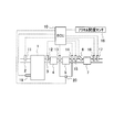
- FIG. 1 is a diagram illustrating a schematic configuration of an exhaust gas purification apparatus for an internal combustion engine according to Embodiments 1 and 2.
- FIG. It is a schematic block diagram of PM sensor. It is the time chart which showed transition of the detection value of PM sensor with the case where a filter is normal, and when it has failed. It is the time chart which showed transition with the case where the detection value of PM sensor is normal, and the case where it is abnormal. It is the figure which showed the relationship between the travel time of the vehicle in which an internal combustion engine is mounted, and the integrated value of PM amount (passing PM amount) passing through a filter.
- 3 is a flowchart illustrating a flow of filter failure determination according to the first embodiment.
- FIG. 10 is a flowchart illustrating a flow of filter failure determination according to the second embodiment.
- FIG. 1 is a diagram showing a schematic configuration of an exhaust gas purification apparatus for an internal combustion engine according to the present embodiment.
- the internal combustion engine 1 shown in FIG. 1 may be a gasoline engine or a diesel engine.
- An intake passage 2 and an exhaust passage 3 are connected to the internal combustion engine 1.
- An air flow meter 11 that detects the amount of intake air flowing through the intake passage 2 is provided in the intake passage 2.
- an oxidation catalyst 4 a filter 5, an injection valve 6, and a selective reduction type NOx catalyst 7 (hereinafter referred to as NOx catalyst 7) are provided in order from the upstream side in the exhaust flow direction.
- the oxidation catalyst 4 may be any catalyst having oxidation ability, and may be, for example, a three-way catalyst.
- the oxidation catalyst 4 may be carried on the filter 5.
- the filter 5 collects PM in the exhaust.
- the filter 5 may carry a catalyst. As PM is collected by the filter 5, PM gradually accumulates on the filter 5. Then, by executing a so-called filter regeneration process for forcibly increasing the temperature of the filter 5, the PM deposited on the filter 5 can be oxidized and removed.
- the temperature of the filter 5 can be raised by supplying HC to the oxidation catalyst 4.
- the temperature of the filter 5 may be raised by discharging hot gas from the internal combustion engine 1.
- the injection valve 6 injects urea water.
- the urea water injected from the injection valve 6 is hydrolyzed in the NOx catalyst 7 to become ammonia (NH 3 ), and part or all of the urea water is adsorbed on the NOx catalyst 7.
- This ammonia is used as a reducing agent in the NOx catalyst 7.
- the injection valve 6 corresponds to the supply device in the present invention. Instead of injecting urea water, a device that supplies solid urea can also be used.
- NOx catalyst 7 reduces NOx in the exhaust when a reducing agent is present. Therefore, if ammonia is adsorbed on the NOx catalyst 7 in advance, the NOx can be reduced with ammonia in the NOx catalyst 7.
- a first exhaust temperature sensor 12 for detecting the exhaust temperature is provided in the exhaust passage 3 upstream of the oxidation catalyst 4.
- a second exhaust temperature sensor 13 for detecting the temperature of the exhaust gas is provided in the exhaust passage 3 downstream of the oxidation catalyst 4 and upstream of the filter 5.
- the exhaust passage 3 downstream of the filter 5 and upstream of the injection valve 6 is provided with a third exhaust temperature sensor 14 for detecting the temperature of the exhaust and a first NOx sensor 15 for detecting the NOx concentration in the exhaust. Yes.
- a second NOx sensor 16 for detecting the NOx concentration in the exhaust and a PM sensor 17 for detecting the PM amount in the exhaust are provided in the exhaust passage 3 downstream of the NOx catalyst 7.
- the exhaust passage 3 has a pressure in the exhaust passage 3 downstream from the oxidation catalyst 4 and upstream from the filter 5, and a pressure in the exhaust passage 3 downstream from the filter 5 and upstream from the NOx catalyst 7. And a differential pressure sensor 20 for detecting the difference between the two.
- the differential pressure sensor 20 can detect a pressure difference between the upstream side and the downstream side of the filter 5 (hereinafter also referred to as filter differential pressure). Note that all of these sensors are not essential, and can be provided as necessary.
- the internal combustion engine 1 configured as described above is provided with an ECU 10 that is an electronic control unit for controlling the internal combustion engine 1.
- the ECU 10 controls the internal combustion engine 1 in accordance with the operating conditions of the internal combustion engine 1 and the driver's request.
- the ECU 10 outputs an electrical signal corresponding to the amount of depression of the accelerator pedal to detect an engine load, and an accelerator opening sensor 18 that detects an engine load, and a crank position sensor 19 that detects an engine speed are electrically wired.
- the output signals of these sensors are input to the ECU 10.
- the injection valve 6 is connected to the ECU 10 via electric wiring, and the injection valve 6 is controlled by the ECU 10.
- the ECU 10 performs the regeneration process of the filter.
- the filter regeneration process may be performed when the travel distance of the vehicle on which the internal combustion engine 1 is mounted becomes equal to or greater than a predetermined distance. In addition, the filter regeneration process may be performed every specified period.
- the ECU 10 determines a failure of the filter 5 based on the PM amount detected by the PM sensor 17.
- the PM sensor 17 determines a failure of the filter 5 based on the PM amount detected by the PM sensor 17.
- a failure such as breakage of the filter 5 occurs, the amount of PM passing through the filter 5 increases. If this increase in PM amount is detected by the PM sensor 17, the failure of the filter 5 can be determined.
- the failure determination of the filter 5 is based on the integrated value of the PM amount calculated during the predetermined period calculated based on the detection value of the PM sensor 17 and the PM during the predetermined period when the filter 5 is assumed to be in the predetermined state. This is done by comparing the integrated value of the quantity.
- FIG. 2 is a schematic configuration diagram of the PM sensor 17.
- the PM sensor 17 is a sensor that outputs an electrical signal corresponding to the amount of PM deposited on itself.
- the PM sensor 17 includes a pair of electrodes 171 and an insulator 172 provided between the pair of electrodes 171.
- the electrical resistance between the pair of electrodes 171 changes. Since this change in electrical resistance has a correlation with the amount of PM in the exhaust, the amount of PM in the exhaust can be detected based on the change in the electrical resistance.
- This amount of PM may be the mass of PM per unit time, or may be the mass of PM in a predetermined time.
- the configuration of the PM sensor 17 is not limited to that shown in FIG. That is, any PM sensor may be used as long as it detects PM and changes in the detection value due to the influence of urea.
- the PM sensor 17 is provided on the downstream side of the filter 5. Therefore, PM that has passed through the filter 5 adheres to the PM sensor 17 without being collected by the filter 5. Therefore, the PM accumulation amount in the PM sensor 17 is an amount corresponding to the integrated value of the PM amount that has passed through the filter 5.
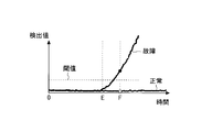
- FIG. 3 is a time chart showing the transition of the detection value of the PM sensor 17 when the filter 5 is normal and when it is malfunctioning.
- PM accumulates early on the PM sensor 17, so that the time point E at which the detection value starts increasing is earlier than that of the normal filter 5. For this reason, for example, if the detected value when the predetermined time F has elapsed since the start of the internal combustion engine 1 is equal to or greater than the threshold value, it can be determined that the filter 5 has failed.
- the predetermined time F is a time when the detection value of the PM sensor 17 does not increase if the filter 5 is normal, and the detection value of the PM sensor 17 increases if the filter 5 is faulty. is there.
- This predetermined time F is obtained by experiments or the like.
- the threshold value is obtained in advance by experiments or the like as the lower limit value of the detection value of the PM sensor 17 when the filter 5 is out of order.
- the PM sensor 17 is provided downstream of the filter 5 and upstream of the NOx catalyst 7.
- the distance from the filter 5 to the PM sensor 17 is shortened.
- PM that has passed through the cracked portion of the filter 5 reaches the periphery of the PM sensor 17 without being dispersed in the exhaust gas.
- PM hardly adheres to the PM sensor 17, so PM may not be detected, and the accuracy of failure determination may be reduced.
- the reducing agent (urea) injected from the injection valve 6 may adhere to the PM sensor 17. If the reducing agent adheres to the PM sensor 17, the detection value of the PM sensor 17 may change.
- the hydrolysis of urea is prevented by the PM. Then, urea that is not hydrolyzed flows out of the NOx catalyst 7 without reacting with the NOx catalyst 7. That is, when PM covers the NOx catalyst 7, urea passes through the NOx catalyst 7. When this urea adheres to the PM sensor 17, the detection value of the PM sensor 17 changes.
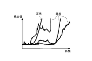
- FIG. 4 is a time chart showing the transition between when the detection value of the PM sensor 17 is normal and when it is abnormal.
- the case where the detection value is abnormal is a case where the detection value is changed due to a reducing agent adhering to the PM sensor 17.
- the normal detection value increases with time. That is, the detected value increases in accordance with the amount of PM attached to the PM sensor 17.
- an abnormal detection value may decrease as well as increase in the detection value.
- abnormal detection values may take time to increase.
- urea adheres to the PM sensor 17 and accumulates a predetermined amount or more the detection value of the PM sensor 17 increases as in the case where PM accumulates.
- the amount of urea deposited decreases, and the detection value of the PM sensor 17 decreases. This is a phenomenon that does not occur when only PM is deposited on the PM sensor 17.
- the amount of PM adhering to the NOx catalyst 7 (hereinafter also referred to as PM accumulation amount) is estimated or detected, and when this PM accumulation amount exceeds a threshold value, the NOx catalyst 7 It is considered that urea passes through the NOx catalyst 7 due to PM adhering to the catalyst.
- the PM accumulation amount has a correlation with an integrated value of the PM amount passing through the filter 5 (also referred to as “passing PM amount”). For this reason, when the passing-through PM amount is estimated or detected, and the integrated value of the passing-through PM amount is equal to or greater than a predetermined value, it is considered that the PM accumulation amount is equal to or greater than the threshold value.
- the amount of PM adhering to the NOx catalyst 7 is considered to be equal to or greater than a threshold value. Also good.
- the normal range may be obtained from the amount of PM discharged from the internal combustion engine 1.
- the predetermined value here is the lower limit of the absolute value of the difference between the range in which the detection value of the PM sensor 17 is normal and the detection value of the PM sensor 17 when urea is attached to the PM sensor 17. It is good. Further, as shown in FIG. 4, when urea adheres to the PM sensor 17, the detection value of the PM sensor 17 can decrease. Therefore, when the detection value of the PM sensor 17 decreases, it may be considered that the detection value of the PM sensor 17 deviates from a normal range by a predetermined value or more.
- the urea water injection from the injection valve 6 is limited. At the same time, failure determination of the filter 5 may be prohibited. Further, use of the detection value of the PM sensor 17 may be prohibited. In addition, restricting the injection of urea water from the injection valve 6 can include prohibiting the injection of urea water or reducing the injection amount of urea water.
- the amount of reducing agent adsorbed by the NOx catalyst 7 when the PM accumulation amount is equal to or greater than the threshold is an amount capable of purifying NOx, the urea water injection from the injection valve 6 is prohibited, while the NOx If the amount is less than the amount that can be purified, the failure determination of the filter 5 may be prohibited while permitting the injection of urea water from the injection valve 6.
- the PM accumulation amount increases according to the integrated value of the passing-through PM amount. For this reason, when the accumulated value of the passing-through PM amount reaches a predetermined value, the PM accumulation amount exceeds the allowable range.
- the allowable range of this PM accumulation amount is determined so that the amount of urea passing through the NOx catalyst 7 falls within the allowable range. Then, the integrated value of the passing PM amount is estimated as follows.
- the passing-through PM amount when it is assumed that a failure such as a crack has occurred in the filter 5 is estimated.
- the passing PM amount is obtained by multiplying the PM amount discharged from the internal combustion engine 1 obtained from the operating state of the internal combustion engine 1 by a predetermined value.
- the predetermined value here is a ratio of the PM amount flowing out from the filter 5 to the PM amount flowing into the filter 5 when a failure has occurred in the filter 5, and is hereinafter referred to as a “pass-through rate”.
- the pass-through rate varies depending on the size of the crack of the filter 5 or the degree of the crack (hereinafter also referred to as the crack rate).
- the crack rate is a value representing the degree of failure of the filter 5 and can be determined based on, for example, PM collection efficiency. For example, the crack rate is 0% when it is new, and the crack rate is 100% when PM cannot be collected at all. Further, when the filter 5 is removed, the cracking rate may be 100%.
- the PM amount is set on the assumption that the filter 5 has a predetermined cracking rate.
- the passing PM amount is obtained by multiplying the PM amount discharged from the internal combustion engine 1 by the passing rate. Since the PM amount discharged from the internal combustion engine 1 has a correlation with the engine speed and the fuel injection amount, these relationships are obtained by experiments and mapped beforehand. Then, the PM amount discharged from the internal combustion engine 1 is calculated using this map, the engine speed and the fuel injection amount.
- the pass-through rate varies depending on the filter differential pressure or the amount of exhaust gas flowing into the filter 5, the relationship between the pass-through rate and the filter differential pressure, or the pass-through rate and the amount of exhaust gas flowing into the filter 5.
- the relationship is obtained in advance by experiments or the like and is mapped and stored in the ECU 10. For example, when the cracking rate of the filter 5 is large to some extent, the passing-through rate increases as the filter differential pressure increases.
- the amount of exhaust can be obtained based on the intake air amount of the internal combustion engine 1 and the fuel supply amount to the internal combustion engine 1. Then, by calculating and adding the passing PM amount every predetermined time, an integrated value of the passing PM amount can be obtained.
- FIG. 5 is a diagram showing the relationship between the travel time of the vehicle on which the internal combustion engine 1 is mounted and the integrated value of the PM amount passing through the filter 5 (passing PM amount).
- the travel time of the vehicle may be the travel distance of the vehicle.
- the integrated value of the passing PM amount is correlated with the PM amount adhering to the NOx catalyst 7. This relationship can be obtained in advance by experiments or the like.
- the accumulated value of the passing PM amount becomes equal to or greater than a predetermined value
- the amount of PM adhering to the NOx catalyst 7 becomes equal to or greater than the threshold value, so that the process of removing the PM adhering to the NOx catalyst 7 is performed.
- PM may be removed by attaching a heater to the NOx catalyst 7 and increasing the temperature of the NOx catalyst 7. Further, similarly to the regeneration process of the filter 5, the temperature of the exhaust gas flowing into the NOx catalyst 7 may be increased. Further, the temperature of the exhaust gas flowing into the NOx catalyst 7 may be increased by performing the regeneration process of the filter 5. Thus, when the PM adhering to the NOx catalyst 7 is removed, the integrated value of the passing-through PM amount decreases and becomes zero.
- the ECU 10 that performs the process of removing PM from the NOx catalyst 7 corresponds to the removing unit in the present invention.
- the urea supply amount is limited. Further, the failure determination of the filter 5 is prohibited, or the use of the detection value of the PM sensor 17 is prohibited.
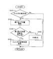
- FIG. 6 is a flowchart showing a flow of failure determination of the filter 5 according to the present embodiment. This routine is executed every predetermined time by the ECU 10.
- step S101 it is determined whether or not the regeneration process of the filter 5 has been performed.
- PM adhering to the NOx catalyst 7 and urea adhering to the PM sensor 17 are removed. That is, the integrated value of the passing-through PM amount becomes zero. Such a state is a precondition.
- step S101 If an affirmative determination is made in step S101, the process proceeds to step S102. On the other hand, if a negative determination is made, the precondition is not satisfied, and this routine is terminated.
- step S102 the passing-through PM amount is integrated.
- the passing-through PM amount is obtained as a value having a correlation with the PM amount adhering to the NOx catalyst 7 (PM accumulation amount).
- the passing PM amount is obtained by multiplying the PM amount discharged from the internal combustion engine 1 by the passing rate. Then, by calculating and adding the passing PM amount every predetermined time, an integrated value of the passing PM amount is obtained.
- the process of step S102 proceeds to step S103.
- step S103 it is determined whether or not the integrated value of the passing-through PM amount is less than a predetermined value.
- This predetermined value is obtained in advance by experiments or the like as the lower limit value of the integrated value of the passing-through PM amount that prevents the hydrolysis of urea in the NOx catalyst 7. That is, in this step, it is determined whether or not urea is normally hydrolyzed in the NOx catalyst 7. If an affirmative determination is made in step S103, the process proceeds to step S104. On the other hand, if a negative determination is made, the process proceeds to step S105.
- step S104 the failure determination of the filter 5 is performed using the PM sensor 17. At this time, the supply of urea is permitted. When the process of step S104 is completed, this routine is terminated.
- step S105 a process of removing PM adhering to the NOx catalyst 7 is performed. For example, by supplying HC to the oxidation catalyst 4, the temperature of the exhaust gas flowing into the NOx catalyst 7 is raised to oxidize PM. At this time, failure detection of the filter 5 is prohibited, and the supply of urea from the injection valve 6 is restricted.
- the process of step S105 is completed, the process returns to step S102.
- the ECU 10 that processes step S105 corresponds to a restriction unit or a prohibition unit in the present invention.
- the supply of urea is limited, or the failure determination of the filter 5 is performed. Or the use of the detection value of the PM sensor 17 can be prohibited. Thereby, it can suppress that the detection accuracy of PM sensor 17 falls, or it can control that an incorrect judgment is made in failure judgment of filter 5. That is, it can suppress that the accuracy of the failure determination of the filter 5 falls.
- the present embodiment can be applied even when the filter 5 is not provided.
- the passing PM amount may be considered to be the same as the PM amount discharged from the internal combustion engine 1. Moreover, it is good also considering a penetration rate and a crack rate as 100%.
- Example 2 In the present embodiment, the method for setting the pass-through rate is different from that in the first embodiment. Further, the differential pressure sensor 20 is used in combination when determining the failure of the filter 5. Since other devices are the same as those in the first embodiment, the description thereof is omitted.
- the degree of failure (cracking rate) of the filter 5 is the minimum degree of failure (cracking rate) that can be determined by the differential pressure sensor 20 that the filter 5 has failed. Then, the pass-through rate or the pass-through PM amount is set. Note that the differential pressure sensor 20 cannot detect a crack in the filter 5 because the change in the differential pressure is small when the crack rate is small. Also, if the passing rate is set on the assumption that the filter 5 has a boundary whether or not the cracking rate exceeds the allowable range, when the filter 5 is removed by the user, a large amount of PM is transferred to the NOx catalyst 7 and PM. When the sensor 17 is reached, the actual pass-through rate is higher than the estimated pass-through rate. Therefore, an abnormality occurs in the detected value of the PM sensor 17 before the failure determination of the filter 5 is prohibited. For this reason, there is a possibility that the accuracy of the failure determination of the filter 5 is lowered.
- the passing-through rate is set in consideration of removal of the filter 5 or the like, the estimated passing-through PM amount increases. Therefore, since the integrated value of the estimated passing-through PM amount frequently reaches a predetermined value, supply of urea Is often restricted. That is, as shown in FIG. 5, when the integrated value of the passing-through PM amount is larger than a predetermined value, and when the process of removing PM from the NOx catalyst 7 is being performed, the urea supply restriction is performed. The Then, if the accumulated value of the passing-through PM amount frequently exceeds a predetermined value, the opportunity for determining the failure of the filter 5 also decreases.
- the failure degree (cracking rate) of the filter 5 is the minimum failure degree (cracking rate) that can be determined by the differential pressure sensor 20 that the filter 5 has failed. Assuming that the passing-through rate and the passing-through PM amount are estimated. The pass-through rate and the pass-through PM amount can be obtained based on the map in the same manner as in the first embodiment.
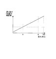
- FIG. 7 is a diagram showing the relationship between the degree of failure (breaking rate) of the filter 5 and the integrated value of the passing PM amount when the vehicle on which the internal combustion engine 1 is mounted travels for a predetermined time.
- the cracking rate of the filter 5 indicated by A is a regulation value or an upper limit value of an allowable range. That is, when the actual cracking rate is larger than the cracking rate of the filter 5 indicated by A, it is necessary to determine that the filter 5 has failed.
- the cracking rate of the filter 5 indicated by B is a lower limit value of the cracking rate that can be determined by the differential pressure sensor 20 that the filter 5 has failed.
- the failure determination of the filter 5 is performed using the detection value of the PM sensor 17.
- the cracking rate of the filter 5 is equal to or greater than B
- the integrated value of the actual passing PM amount becomes larger than the estimated passing PM amount integrated value, so that the detection value of the PM sensor 17 may become abnormal. There is.
- the failure determination of the filter 5 is performed using the differential pressure sensor 20 instead of the PM sensor 17, the accuracy of the failure determination can be improved.
- the passing-through PM amount is estimated to be small compared with the case where the passing-through rate is set in consideration of the removal of the filter 5 or the like, it is possible to suppress the frequent supply of urea. Moreover, it can suppress that the failure determination of the filter 5 is frequently prohibited. Further, it is possible to suppress the occurrence of an abnormality in the detection value of the PM sensor 17 due to a large amount of urea adhering to the PM sensor 17. Further, even if a crack larger than expected such as removal of the filter 5 occurs, the failure of the filter 5 can be determined by the differential pressure sensor 20.
- the passing rate is set. Even when the passing rate is actually larger, the failure of the filter 5 can be determined using the differential pressure sensor 20. That is, when the cracking rate of the filter 5 is so large that a failure can be determined by the differential pressure sensor 20, the actual passing-through PM amount is larger than the estimated passing-through PM amount. Will deposit more PM than expected. For this reason, urea passes through the NOx catalyst 7 and adheres to the PM sensor 17, and the detection accuracy of the PM sensor 17 decreases. Even in such a case, the failure of the filter 5 can be determined by the differential pressure sensor 20 because the crack rate is large.
- the actual passing-through PM amount is larger than the estimated passing-through PM amount. Becomes smaller. For this reason, the integrated value of the actual passing PM amount reaches the predetermined value after the estimated integrated value of the passing PM amount reaches the predetermined value. Then, when the accumulated value of the passing-through PM amount reaches a predetermined value, processing for removing the PM adhering to the NOx catalyst 7 is performed, so that the accumulated value of the passing-through PM amount reaches the predetermined value. Before, PM adhering to the NOx catalyst 7 is removed.
- the estimated passing-through PM amount integrated value is greater than or equal to a predetermined value
- urea supply is restricted, so that urea does not pass through the NOx catalyst 7, and urea adheres to the PM sensor 17. Can be suppressed. Thereby, the accuracy of the failure determination of the filter 5 can be improved.
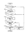
- FIG. 8 is a flowchart showing a flow for determining the failure of the filter 5 according to the present embodiment. This routine is executed every predetermined time by the ECU 10. In addition, about the step in which the same process as the flow shown in FIG. 6 is made, the same code
- step S ⁇ b> 201 failure determination of the filter 5 is performed using the differential pressure sensor 20. That is, in this step, failure determination of the filter 5 is performed using the differential pressure sensor 20.
- step S ⁇ b> 201 failure determination of the filter 5 is performed using the differential pressure sensor 20.
- the differential pressure sensor 20 when the differential pressure sensor 20 is used, a failure cannot be detected unless the crack rate of the filter 5 is relatively large. Therefore, in this step, it is determined whether or not a relatively large crack has occurred in the filter 5. Further, in this step, it is determined that the filter 5 has failed even when the filter 5 is removed.
- step S202 it is determined whether or not the filter 5 is normal. That is, in step S201, it is determined whether or not it has been concluded that the filter 5 is normal. When the crack rate of the filter 5 is relatively small, it is determined in step S201 that the filter 5 is normal. Therefore, the failure determination of the filter 5 is performed using the detection value of the PM sensor 17 in the following steps. Is implemented. If an affirmative determination is made in step S202, the process proceeds to step S102. On the other hand, if a negative determination is made, it is determined that the filter 5 has failed, and thus this routine is terminated.
- step S203 the failure determination of the filter 5 using the PM sensor 17 is prohibited. Note that the use of the detection value of the PM sensor 17 may be prohibited. Further, the supply of urea from the injection valve 6 is limited. At this time, since the failure determination of the filter 5 by the differential pressure sensor 20 is performed in Step S201 and Step S202, even if the filter 5 has a failure, the cracking rate is small. For this reason, if PM is removed from the NOx catalyst 7, urea can be supplied, or the failure determination of the filter 5 can be performed by the PM sensor 17.
- step S105 the ECU 10 that processes step S203 corresponds to the limiting unit or the prohibiting unit in the present invention.
- the degree of failure (cracking rate) of the filter 5 is the minimum degree of failure (cracking rate) that can be determined by the differential pressure sensor 20 that the filter 5 has failed.
- the pass-through rate it is possible to suppress the urea supply from being frequently restricted, or to prevent the failure determination of the filter 5 from being frequently prohibited.
- the failure determination of the filter 5 is implemented in the state in which abnormality has arisen in PM sensor 17.
Abstract
Priority Applications (12)
| Application Number | Priority Date | Filing Date | Title |
|---|---|---|---|
| JP2014516554A JP6240068B2 (ja) | 2012-05-22 | 2012-05-22 | 内燃機関の排気浄化装置 |
| GB1422171.7A GB2517376B (en) | 2012-05-22 | 2012-05-22 | Exhaust gas purification apparatus for internal combustion engine |
| PCT/JP2012/063050 WO2013175572A1 (fr) | 2012-05-22 | 2012-05-22 | Dispositif de purification d'émission d'échappement pour moteur à combustion interne |
| US14/402,830 US9550149B2 (en) | 2012-05-22 | 2012-05-22 | Exhaust gas purification apparatus for internal combustion engine |
| BR112014029076A BR112014029076A2 (pt) | 2012-05-22 | 2012-05-22 | dispositivo de purificação de emissão de escape para motor de combustão interna |
| MYPI2014003238A MY178101A (en) | 2012-05-22 | 2012-05-22 | Exhaust gas purification apparatus for internal combustion engine |
| KR1020147033888A KR101643494B1 (ko) | 2012-05-22 | 2012-05-22 | 내연 기관의 배기 정화 장치 |
| AU2012380501A AU2012380501B2 (en) | 2012-05-22 | 2012-05-22 | Exhaust gas purification apparatus for internal combustion engine |
| IN10230DEN2014 IN2014DN10230A (fr) | 2012-05-22 | 2012-05-22 | |
| CN201280073351.4A CN104334844B (zh) | 2012-05-22 | 2012-05-22 | 内燃机的排气净化装置 |
| DE112012006410.0T DE112012006410B4 (de) | 2012-05-22 | 2012-05-22 | Abgasreinigungsvorrichtung für Verbrennungskraftmaschine |
| RU2014148067/06A RU2594090C9 (ru) | 2012-05-22 | 2012-05-22 | Устройство для очистки отработавших газов двигателя внутреннего сгорания |
Applications Claiming Priority (1)
| Application Number | Priority Date | Filing Date | Title |
|---|---|---|---|
| PCT/JP2012/063050 WO2013175572A1 (fr) | 2012-05-22 | 2012-05-22 | Dispositif de purification d'émission d'échappement pour moteur à combustion interne |
Publications (1)
| Publication Number | Publication Date |
|---|---|
| WO2013175572A1 true WO2013175572A1 (fr) | 2013-11-28 |
Family
ID=49623303
Family Applications (1)
| Application Number | Title | Priority Date | Filing Date |
|---|---|---|---|
| PCT/JP2012/063050 WO2013175572A1 (fr) | 2012-05-22 | 2012-05-22 | Dispositif de purification d'émission d'échappement pour moteur à combustion interne |
Country Status (11)
| Country | Link |
|---|---|
| US (1) | US9550149B2 (fr) |
| JP (1) | JP6240068B2 (fr) |
| KR (1) | KR101643494B1 (fr) |
| CN (1) | CN104334844B (fr) |
| AU (1) | AU2012380501B2 (fr) |
| BR (1) | BR112014029076A2 (fr) |
| DE (1) | DE112012006410B4 (fr) |
| GB (1) | GB2517376B (fr) |
| IN (1) | IN2014DN10230A (fr) |
| RU (1) | RU2594090C9 (fr) |
| WO (1) | WO2013175572A1 (fr) |
Cited By (7)
| Publication number | Priority date | Publication date | Assignee | Title |
|---|---|---|---|---|
| JP2016056701A (ja) * | 2014-09-05 | 2016-04-21 | トヨタ自動車株式会社 | パティキュレートフィルタの異常診断装置 |
| WO2016114111A1 (fr) * | 2015-01-13 | 2016-07-21 | 株式会社デンソー | Dispositif de diagnostic d'anomalie |
| WO2016121386A1 (fr) * | 2015-01-30 | 2016-08-04 | 株式会社デンソー | Dispositif de purification de gaz d'échappement |
| JP2017048709A (ja) * | 2015-09-01 | 2017-03-09 | 日野自動車株式会社 | パティキュレートフィルタの故障診断装置 |
| JPWO2015093603A1 (ja) * | 2013-12-19 | 2017-03-23 | トヨタ自動車株式会社 | 内燃機関の排気浄化システム |
| JP2019509427A (ja) * | 2016-03-21 | 2019-04-04 | シーティーエス・コーポレーションCts Corporation | 高周波プロセス感知、制御、及び診断ネットワーク及びシステム |
| JP2020112040A (ja) * | 2019-01-08 | 2020-07-27 | トヨタ自動車株式会社 | 内燃機関の制御装置 |
Families Citing this family (14)
| Publication number | Priority date | Publication date | Assignee | Title |
|---|---|---|---|---|
| DE102013221598A1 (de) * | 2013-10-24 | 2015-05-13 | Robert Bosch Gmbh | Verfahren und Vorrichtung zur Überwachung eines Partikelfilters |
| WO2015188189A1 (fr) | 2014-06-06 | 2015-12-10 | Filter Sensing Technologies, Inc. | Procédé et système de mesure de variable d'état de fréquence radio |
| WO2015188188A1 (fr) | 2014-06-06 | 2015-12-10 | Filter Sensing Technologies, Inc. | Détection, et commande, de processus radiofréquence, réseau de diagnostic |
| JP2017538106A (ja) | 2014-10-20 | 2017-12-21 | フィルター・センシング・テクノロジーズ・インコーポレイテッドFilter Sensing Technologies,Inc. | フィルターろ過残渣の分析及び診断 |
| JP6256392B2 (ja) * | 2015-03-17 | 2018-01-10 | トヨタ自動車株式会社 | フィルタの異常検出装置 |
| JP6252537B2 (ja) * | 2015-04-02 | 2017-12-27 | トヨタ自動車株式会社 | パティキュレートフィルタの異常診断装置 |
| JP6137229B2 (ja) * | 2015-04-02 | 2017-05-31 | トヨタ自動車株式会社 | パティキュレートフィルタの異常診断装置 |
| US10799826B2 (en) * | 2015-06-08 | 2020-10-13 | Cts Corporation | Radio frequency process sensing, control, and diagnostics network and system |
| US10260400B2 (en) | 2015-06-08 | 2019-04-16 | Cts Corporation | Radio frequency system and method for monitoring engine-out exhaust constituents |
| FR3042223B1 (fr) * | 2015-10-12 | 2017-12-08 | Renault Sas | Dispositif de post-traitement des gaz d'echappement d'un moteur a combustion interne de vehicule automobile |
| DE102017109626A1 (de) * | 2017-05-04 | 2018-11-08 | Volkswagen Aktiengesellschaft | Abgasanlage für einen Verbrennungsmotor sowie Verfahren zum Betreiben einer solchen Abgasanlage |
| WO2019143595A1 (fr) | 2018-01-16 | 2019-07-25 | Cts Corporation | Système de capteur radiofréquence incorporant un système et un procédé d'apprentissage automatique |
| EP3786614A1 (fr) * | 2019-08-29 | 2021-03-03 | Carl Freudenberg KG | Procédé de fourniture d'un flux d'air |
| CN113653552B (zh) * | 2021-09-06 | 2023-01-06 | 安徽江淮汽车集团股份有限公司 | Scr系统尿素喷射控制方法 |
Citations (4)
| Publication number | Priority date | Publication date | Assignee | Title |
|---|---|---|---|---|
| JP2000008840A (ja) * | 1998-06-18 | 2000-01-11 | Nippon Soken Inc | 排気浄化用触媒の機能回復装置と機能回復方法 |
| JP2006125247A (ja) * | 2004-10-27 | 2006-05-18 | Hitachi Ltd | エンジンの排気ガス浄化方法及び排気ガス浄化装置 |
| JP2010229957A (ja) * | 2009-03-30 | 2010-10-14 | Ngk Spark Plug Co Ltd | 内燃機関の排気システム及びそれに用いる粒子状物質測定センサ |
| JP2012031826A (ja) * | 2010-08-02 | 2012-02-16 | Toyota Motor Corp | 排気浄化装置の異常検出システム |
Family Cites Families (13)
| Publication number | Priority date | Publication date | Assignee | Title |
|---|---|---|---|---|
| RU2120039C1 (ru) * | 1996-05-17 | 1998-10-10 | Василий Алексеевич Звонов | Электромеханический фильтр |
| JP2002136842A (ja) * | 2000-11-06 | 2002-05-14 | Isuzu Ceramics Res Inst Co Ltd | 排気ガス浄化装置 |
| JP4650222B2 (ja) * | 2005-11-11 | 2011-03-16 | トヨタ自動車株式会社 | Pmトラッパ故障検出装置 |
| KR100836367B1 (ko) * | 2006-11-21 | 2008-06-09 | 현대자동차주식회사 | 디젤엔진의 입자상물질과 질소산화물 저감을 위한 정화장치 |
| US7874147B2 (en) * | 2007-04-26 | 2011-01-25 | Emcon Technologies Llc | Method and apparatus for a non-catalytic NOx reduction |
| DE102007046460A1 (de) * | 2007-09-28 | 2009-04-02 | Daimler Ag | Verfahren zur Verminderung der Emission von Stickstoffdioxid bei einem Kraftfahrzeug mit einer mager betriebenen Brennkraftmaschine |
| US8397489B2 (en) * | 2008-09-10 | 2013-03-19 | Ford Global Technologies, Llc | Engine idling duration control |
| JP4756068B2 (ja) * | 2008-12-22 | 2011-08-24 | 本田技研工業株式会社 | 排気浄化フィルタの故障検知装置 |
| JP2010248952A (ja) * | 2009-04-13 | 2010-11-04 | Honda Motor Co Ltd | 触媒の劣化判定装置 |
| JP2010275917A (ja) | 2009-05-28 | 2010-12-09 | Honda Motor Co Ltd | 粒子状物質検出手段の故障判定装置 |
| JP5056898B2 (ja) | 2010-05-17 | 2012-10-24 | トヨタ自動車株式会社 | 排気浄化装置の故障検出装置 |
| US8490476B2 (en) * | 2011-03-08 | 2013-07-23 | Ford Global Technologies, Llc | Method for diagnosing operation of a particulate matter sensor |
| US8627645B2 (en) * | 2011-05-25 | 2014-01-14 | Ford Global Technologies, Llc | Emission control with a particulate matter sensor |
-
2012
- 2012-05-22 GB GB1422171.7A patent/GB2517376B/en not_active Expired - Fee Related
- 2012-05-22 AU AU2012380501A patent/AU2012380501B2/en not_active Ceased
- 2012-05-22 JP JP2014516554A patent/JP6240068B2/ja not_active Expired - Fee Related
- 2012-05-22 WO PCT/JP2012/063050 patent/WO2013175572A1/fr active Application Filing
- 2012-05-22 US US14/402,830 patent/US9550149B2/en not_active Expired - Fee Related
- 2012-05-22 CN CN201280073351.4A patent/CN104334844B/zh not_active Expired - Fee Related
- 2012-05-22 BR BR112014029076A patent/BR112014029076A2/pt not_active Application Discontinuation
- 2012-05-22 RU RU2014148067/06A patent/RU2594090C9/ru not_active IP Right Cessation
- 2012-05-22 DE DE112012006410.0T patent/DE112012006410B4/de not_active Expired - Fee Related
- 2012-05-22 KR KR1020147033888A patent/KR101643494B1/ko active IP Right Grant
- 2012-05-22 IN IN10230DEN2014 patent/IN2014DN10230A/en unknown
Patent Citations (4)
| Publication number | Priority date | Publication date | Assignee | Title |
|---|---|---|---|---|
| JP2000008840A (ja) * | 1998-06-18 | 2000-01-11 | Nippon Soken Inc | 排気浄化用触媒の機能回復装置と機能回復方法 |
| JP2006125247A (ja) * | 2004-10-27 | 2006-05-18 | Hitachi Ltd | エンジンの排気ガス浄化方法及び排気ガス浄化装置 |
| JP2010229957A (ja) * | 2009-03-30 | 2010-10-14 | Ngk Spark Plug Co Ltd | 内燃機関の排気システム及びそれに用いる粒子状物質測定センサ |
| JP2012031826A (ja) * | 2010-08-02 | 2012-02-16 | Toyota Motor Corp | 排気浄化装置の異常検出システム |
Cited By (12)
| Publication number | Priority date | Publication date | Assignee | Title |
|---|---|---|---|---|
| JPWO2015093603A1 (ja) * | 2013-12-19 | 2017-03-23 | トヨタ自動車株式会社 | 内燃機関の排気浄化システム |
| JP2016056701A (ja) * | 2014-09-05 | 2016-04-21 | トヨタ自動車株式会社 | パティキュレートフィルタの異常診断装置 |
| US9599004B2 (en) | 2014-09-05 | 2017-03-21 | Toyota Jidosha Kabushiki Kaisha | Abnormality diagnostic device for a particulate filter |
| WO2016114111A1 (fr) * | 2015-01-13 | 2016-07-21 | 株式会社デンソー | Dispositif de diagnostic d'anomalie |
| JP2016130457A (ja) * | 2015-01-13 | 2016-07-21 | 株式会社デンソー | 異常診断装置 |
| WO2016121386A1 (fr) * | 2015-01-30 | 2016-08-04 | 株式会社デンソー | Dispositif de purification de gaz d'échappement |
| JP2016142139A (ja) * | 2015-01-30 | 2016-08-08 | 株式会社デンソー | 排出ガス浄化装置 |
| JP2017048709A (ja) * | 2015-09-01 | 2017-03-09 | 日野自動車株式会社 | パティキュレートフィルタの故障診断装置 |
| JP2019509427A (ja) * | 2016-03-21 | 2019-04-04 | シーティーエス・コーポレーションCts Corporation | 高周波プロセス感知、制御、及び診断ネットワーク及びシステム |
| JP7208007B2 (ja) | 2016-03-21 | 2023-01-18 | シーティーエス・コーポレーション | 高周波プロセス感知、制御、及び診断ネットワーク及びシステム |
| JP2020112040A (ja) * | 2019-01-08 | 2020-07-27 | トヨタ自動車株式会社 | 内燃機関の制御装置 |
| JP7056588B2 (ja) | 2019-01-08 | 2022-04-19 | トヨタ自動車株式会社 | 内燃機関の制御装置 |
Also Published As
| Publication number | Publication date |
|---|---|
| CN104334844A (zh) | 2015-02-04 |
| RU2594090C9 (ru) | 2016-12-20 |
| DE112012006410B4 (de) | 2020-04-16 |
| US20150132187A1 (en) | 2015-05-14 |
| DE112012006410T5 (de) | 2015-03-19 |
| AU2012380501B2 (en) | 2016-03-31 |
| JP6240068B2 (ja) | 2017-11-29 |
| GB2517376A (en) | 2015-02-18 |
| KR101643494B1 (ko) | 2016-07-27 |
| RU2594090C2 (ru) | 2016-08-10 |
| BR112014029076A2 (pt) | 2017-06-27 |
| JPWO2013175572A1 (ja) | 2016-01-12 |
| US9550149B2 (en) | 2017-01-24 |
| IN2014DN10230A (fr) | 2015-08-07 |
| GB2517376B (en) | 2018-03-21 |
| KR20150003907A (ko) | 2015-01-09 |
| AU2012380501A1 (en) | 2014-12-11 |
| CN104334844B (zh) | 2017-02-22 |
| RU2014148067A (ru) | 2016-07-10 |
Similar Documents
| Publication | Publication Date | Title |
|---|---|---|
| WO2013175572A1 (fr) | Dispositif de purification d'émission d'échappement pour moteur à combustion interne | |
| JP5120464B2 (ja) | 排気浄化装置の異常検出装置及び排気浄化装置の異常検出方法 | |
| JP5590241B2 (ja) | 内燃機関の排気浄化装置 | |
| JP6201822B2 (ja) | 内燃機関の排気浄化システム及び、内燃機関の排気浄化システムのフィルタ故障判定方法 | |
| JP5344093B2 (ja) | 内燃機関の排気浄化装置 | |
| JP6107768B2 (ja) | 排気浄化システムの故障診断装置 | |
| JP5692397B2 (ja) | 内燃機関の排気浄化装置 | |
| JP5692398B2 (ja) | 内燃機関の排気浄化装置 | |
| JP2013087653A (ja) | 内燃機関の排気浄化装置 | |
| JP5344096B2 (ja) | 内燃機関の排気浄化装置 | |
| JP2013108452A (ja) | フィルタの故障検出装置 | |
| JP2013096285A (ja) | 内燃機関の排気浄化装置 | |
| JP2013234624A (ja) | 内燃機関の排気浄化装置の異常判定システム | |
| JP2013087652A (ja) | 内燃機関の排気浄化装置 | |
| JP2013087651A (ja) | 内燃機関の排気浄化装置 |
Legal Events
| Date | Code | Title | Description |
|---|---|---|---|
| 121 | Ep: the epo has been informed by wipo that ep was designated in this application |
Ref document number: 12877394 Country of ref document: EP Kind code of ref document: A1 |
|
| ENP | Entry into the national phase |
Ref document number: 2014516554 Country of ref document: JP Kind code of ref document: A |
|
| WWE | Wipo information: entry into national phase |
Ref document number: 14402830 Country of ref document: US |
|
| WWE | Wipo information: entry into national phase |
Ref document number: 1120120064100 Country of ref document: DE Ref document number: 112012006410 Country of ref document: DE |
|
| ENP | Entry into the national phase |
Ref document number: 20147033888 Country of ref document: KR Kind code of ref document: A |
|
| ENP | Entry into the national phase |
Ref document number: 2012380501 Country of ref document: AU Date of ref document: 20120522 Kind code of ref document: A |
|
| ENP | Entry into the national phase |
Ref document number: 1422171 Country of ref document: GB Kind code of ref document: A Free format text: PCT FILING DATE = 20120522 |
|
| WWE | Wipo information: entry into national phase |
Ref document number: 1422171.7 Country of ref document: GB |
|
| ENP | Entry into the national phase |
Ref document number: 2014148067 Country of ref document: RU Kind code of ref document: A |
|
| REG | Reference to national code |
Ref country code: BR Ref legal event code: B01A Ref document number: 112014029076 Country of ref document: BR |
|
| 122 | Ep: pct application non-entry in european phase |
Ref document number: 12877394 Country of ref document: EP Kind code of ref document: A1 |
|
| ENP | Entry into the national phase |
Ref document number: 112014029076 Country of ref document: BR Kind code of ref document: A2 Effective date: 20141121 |