WO2013157484A1 - 電気駆動車両 - Google Patents
電気駆動車両 Download PDFInfo
- Publication number
- WO2013157484A1 WO2013157484A1 PCT/JP2013/060971 JP2013060971W WO2013157484A1 WO 2013157484 A1 WO2013157484 A1 WO 2013157484A1 JP 2013060971 W JP2013060971 W JP 2013060971W WO 2013157484 A1 WO2013157484 A1 WO 2013157484A1
- Authority
- WO
- WIPO (PCT)
- Prior art keywords
- wheel
- vibration frequency
- pitching vibration
- value
- slip ratio
- Prior art date
- Legal status (The legal status is an assumption and is not a legal conclusion. Google has not performed a legal analysis and makes no representation as to the accuracy of the status listed.)
- Ceased
Links
Images










Classifications
-
- B—PERFORMING OPERATIONS; TRANSPORTING
- B60—VEHICLES IN GENERAL
- B60L—PROPULSION OF ELECTRICALLY-PROPELLED VEHICLES; SUPPLYING ELECTRIC POWER FOR AUXILIARY EQUIPMENT OF ELECTRICALLY-PROPELLED VEHICLES; ELECTRODYNAMIC BRAKE SYSTEMS FOR VEHICLES IN GENERAL; MAGNETIC SUSPENSION OR LEVITATION FOR VEHICLES; MONITORING OPERATING VARIABLES OF ELECTRICALLY-PROPELLED VEHICLES; ELECTRIC SAFETY DEVICES FOR ELECTRICALLY-PROPELLED VEHICLES
- B60L15/00—Methods, circuits, or devices for controlling the traction-motor speed of electrically-propelled vehicles
- B60L15/20—Methods, circuits, or devices for controlling the traction-motor speed of electrically-propelled vehicles for control of the vehicle or its driving motor to achieve a desired performance, e.g. speed, torque, programmed variation of speed
-
- B—PERFORMING OPERATIONS; TRANSPORTING
- B60—VEHICLES IN GENERAL
- B60L—PROPULSION OF ELECTRICALLY-PROPELLED VEHICLES; SUPPLYING ELECTRIC POWER FOR AUXILIARY EQUIPMENT OF ELECTRICALLY-PROPELLED VEHICLES; ELECTRODYNAMIC BRAKE SYSTEMS FOR VEHICLES IN GENERAL; MAGNETIC SUSPENSION OR LEVITATION FOR VEHICLES; MONITORING OPERATING VARIABLES OF ELECTRICALLY-PROPELLED VEHICLES; ELECTRIC SAFETY DEVICES FOR ELECTRICALLY-PROPELLED VEHICLES
- B60L15/00—Methods, circuits, or devices for controlling the traction-motor speed of electrically-propelled vehicles
- B60L15/20—Methods, circuits, or devices for controlling the traction-motor speed of electrically-propelled vehicles for control of the vehicle or its driving motor to achieve a desired performance, e.g. speed, torque, programmed variation of speed
- B60L15/2072—Methods, circuits, or devices for controlling the traction-motor speed of electrically-propelled vehicles for control of the vehicle or its driving motor to achieve a desired performance, e.g. speed, torque, programmed variation of speed for drive off
-
- B—PERFORMING OPERATIONS; TRANSPORTING
- B60—VEHICLES IN GENERAL
- B60L—PROPULSION OF ELECTRICALLY-PROPELLED VEHICLES; SUPPLYING ELECTRIC POWER FOR AUXILIARY EQUIPMENT OF ELECTRICALLY-PROPELLED VEHICLES; ELECTRODYNAMIC BRAKE SYSTEMS FOR VEHICLES IN GENERAL; MAGNETIC SUSPENSION OR LEVITATION FOR VEHICLES; MONITORING OPERATING VARIABLES OF ELECTRICALLY-PROPELLED VEHICLES; ELECTRIC SAFETY DEVICES FOR ELECTRICALLY-PROPELLED VEHICLES
- B60L15/00—Methods, circuits, or devices for controlling the traction-motor speed of electrically-propelled vehicles
- B60L15/20—Methods, circuits, or devices for controlling the traction-motor speed of electrically-propelled vehicles for control of the vehicle or its driving motor to achieve a desired performance, e.g. speed, torque, programmed variation of speed
- B60L15/2009—Methods, circuits, or devices for controlling the traction-motor speed of electrically-propelled vehicles for control of the vehicle or its driving motor to achieve a desired performance, e.g. speed, torque, programmed variation of speed for braking
-
- B—PERFORMING OPERATIONS; TRANSPORTING
- B60—VEHICLES IN GENERAL
- B60L—PROPULSION OF ELECTRICALLY-PROPELLED VEHICLES; SUPPLYING ELECTRIC POWER FOR AUXILIARY EQUIPMENT OF ELECTRICALLY-PROPELLED VEHICLES; ELECTRODYNAMIC BRAKE SYSTEMS FOR VEHICLES IN GENERAL; MAGNETIC SUSPENSION OR LEVITATION FOR VEHICLES; MONITORING OPERATING VARIABLES OF ELECTRICALLY-PROPELLED VEHICLES; ELECTRIC SAFETY DEVICES FOR ELECTRICALLY-PROPELLED VEHICLES
- B60L3/00—Electric devices on electrically-propelled vehicles for safety purposes; Monitoring operating variables, e.g. speed, deceleration or energy consumption
- B60L3/10—Indicating wheel slip ; Correction of wheel slip
- B60L3/106—Indicating wheel slip ; Correction of wheel slip for maintaining or recovering the adhesion of the drive wheels
-
- B—PERFORMING OPERATIONS; TRANSPORTING
- B60—VEHICLES IN GENERAL
- B60L—PROPULSION OF ELECTRICALLY-PROPELLED VEHICLES; SUPPLYING ELECTRIC POWER FOR AUXILIARY EQUIPMENT OF ELECTRICALLY-PROPELLED VEHICLES; ELECTRODYNAMIC BRAKE SYSTEMS FOR VEHICLES IN GENERAL; MAGNETIC SUSPENSION OR LEVITATION FOR VEHICLES; MONITORING OPERATING VARIABLES OF ELECTRICALLY-PROPELLED VEHICLES; ELECTRIC SAFETY DEVICES FOR ELECTRICALLY-PROPELLED VEHICLES
- B60L2200/00—Type of vehicles
- B60L2200/36—Vehicles designed to transport cargo, e.g. trucks
-
- B—PERFORMING OPERATIONS; TRANSPORTING
- B60—VEHICLES IN GENERAL
- B60L—PROPULSION OF ELECTRICALLY-PROPELLED VEHICLES; SUPPLYING ELECTRIC POWER FOR AUXILIARY EQUIPMENT OF ELECTRICALLY-PROPELLED VEHICLES; ELECTRODYNAMIC BRAKE SYSTEMS FOR VEHICLES IN GENERAL; MAGNETIC SUSPENSION OR LEVITATION FOR VEHICLES; MONITORING OPERATING VARIABLES OF ELECTRICALLY-PROPELLED VEHICLES; ELECTRIC SAFETY DEVICES FOR ELECTRICALLY-PROPELLED VEHICLES
- B60L2220/00—Electrical machine types; Structures or applications thereof
- B60L2220/40—Electrical machine applications
- B60L2220/46—Wheel motors, i.e. motor connected to only one wheel
-
- B—PERFORMING OPERATIONS; TRANSPORTING
- B60—VEHICLES IN GENERAL
- B60L—PROPULSION OF ELECTRICALLY-PROPELLED VEHICLES; SUPPLYING ELECTRIC POWER FOR AUXILIARY EQUIPMENT OF ELECTRICALLY-PROPELLED VEHICLES; ELECTRODYNAMIC BRAKE SYSTEMS FOR VEHICLES IN GENERAL; MAGNETIC SUSPENSION OR LEVITATION FOR VEHICLES; MONITORING OPERATING VARIABLES OF ELECTRICALLY-PROPELLED VEHICLES; ELECTRIC SAFETY DEVICES FOR ELECTRICALLY-PROPELLED VEHICLES
- B60L2240/00—Control parameters of input or output; Target parameters
- B60L2240/40—Drive Train control parameters
- B60L2240/42—Drive Train control parameters related to electric machines
- B60L2240/421—Speed
-
- B—PERFORMING OPERATIONS; TRANSPORTING
- B60—VEHICLES IN GENERAL
- B60L—PROPULSION OF ELECTRICALLY-PROPELLED VEHICLES; SUPPLYING ELECTRIC POWER FOR AUXILIARY EQUIPMENT OF ELECTRICALLY-PROPELLED VEHICLES; ELECTRODYNAMIC BRAKE SYSTEMS FOR VEHICLES IN GENERAL; MAGNETIC SUSPENSION OR LEVITATION FOR VEHICLES; MONITORING OPERATING VARIABLES OF ELECTRICALLY-PROPELLED VEHICLES; ELECTRIC SAFETY DEVICES FOR ELECTRICALLY-PROPELLED VEHICLES
- B60L2240/00—Control parameters of input or output; Target parameters
- B60L2240/40—Drive Train control parameters
- B60L2240/42—Drive Train control parameters related to electric machines
- B60L2240/423—Torque
-
- B—PERFORMING OPERATIONS; TRANSPORTING
- B60—VEHICLES IN GENERAL
- B60L—PROPULSION OF ELECTRICALLY-PROPELLED VEHICLES; SUPPLYING ELECTRIC POWER FOR AUXILIARY EQUIPMENT OF ELECTRICALLY-PROPELLED VEHICLES; ELECTRODYNAMIC BRAKE SYSTEMS FOR VEHICLES IN GENERAL; MAGNETIC SUSPENSION OR LEVITATION FOR VEHICLES; MONITORING OPERATING VARIABLES OF ELECTRICALLY-PROPELLED VEHICLES; ELECTRIC SAFETY DEVICES FOR ELECTRICALLY-PROPELLED VEHICLES
- B60L2240/00—Control parameters of input or output; Target parameters
- B60L2240/40—Drive Train control parameters
- B60L2240/46—Drive Train control parameters related to wheels
- B60L2240/461—Speed
-
- B—PERFORMING OPERATIONS; TRANSPORTING
- B60—VEHICLES IN GENERAL
- B60L—PROPULSION OF ELECTRICALLY-PROPELLED VEHICLES; SUPPLYING ELECTRIC POWER FOR AUXILIARY EQUIPMENT OF ELECTRICALLY-PROPELLED VEHICLES; ELECTRODYNAMIC BRAKE SYSTEMS FOR VEHICLES IN GENERAL; MAGNETIC SUSPENSION OR LEVITATION FOR VEHICLES; MONITORING OPERATING VARIABLES OF ELECTRICALLY-PROPELLED VEHICLES; ELECTRIC SAFETY DEVICES FOR ELECTRICALLY-PROPELLED VEHICLES
- B60L2240/00—Control parameters of input or output; Target parameters
- B60L2240/40—Drive Train control parameters
- B60L2240/46—Drive Train control parameters related to wheels
- B60L2240/465—Slip
-
- B—PERFORMING OPERATIONS; TRANSPORTING
- B60—VEHICLES IN GENERAL
- B60L—PROPULSION OF ELECTRICALLY-PROPELLED VEHICLES; SUPPLYING ELECTRIC POWER FOR AUXILIARY EQUIPMENT OF ELECTRICALLY-PROPELLED VEHICLES; ELECTRODYNAMIC BRAKE SYSTEMS FOR VEHICLES IN GENERAL; MAGNETIC SUSPENSION OR LEVITATION FOR VEHICLES; MONITORING OPERATING VARIABLES OF ELECTRICALLY-PROPELLED VEHICLES; ELECTRIC SAFETY DEVICES FOR ELECTRICALLY-PROPELLED VEHICLES
- B60L2260/00—Operating Modes
- B60L2260/20—Drive modes; Transition between modes
- B60L2260/28—Four wheel or all wheel drive
-
- B—PERFORMING OPERATIONS; TRANSPORTING
- B60—VEHICLES IN GENERAL
- B60L—PROPULSION OF ELECTRICALLY-PROPELLED VEHICLES; SUPPLYING ELECTRIC POWER FOR AUXILIARY EQUIPMENT OF ELECTRICALLY-PROPELLED VEHICLES; ELECTRODYNAMIC BRAKE SYSTEMS FOR VEHICLES IN GENERAL; MAGNETIC SUSPENSION OR LEVITATION FOR VEHICLES; MONITORING OPERATING VARIABLES OF ELECTRICALLY-PROPELLED VEHICLES; ELECTRIC SAFETY DEVICES FOR ELECTRICALLY-PROPELLED VEHICLES
- B60L2270/00—Problem solutions or means not otherwise provided for
- B60L2270/10—Emission reduction
- B60L2270/14—Emission reduction of noise
- B60L2270/145—Structure borne vibrations
-
- Y—GENERAL TAGGING OF NEW TECHNOLOGICAL DEVELOPMENTS; GENERAL TAGGING OF CROSS-SECTIONAL TECHNOLOGIES SPANNING OVER SEVERAL SECTIONS OF THE IPC; TECHNICAL SUBJECTS COVERED BY FORMER USPC CROSS-REFERENCE ART COLLECTIONS [XRACs] AND DIGESTS
- Y02—TECHNOLOGIES OR APPLICATIONS FOR MITIGATION OR ADAPTATION AGAINST CLIMATE CHANGE
- Y02T—CLIMATE CHANGE MITIGATION TECHNOLOGIES RELATED TO TRANSPORTATION
- Y02T10/00—Road transport of goods or passengers
- Y02T10/60—Other road transportation technologies with climate change mitigation effect
- Y02T10/64—Electric machine technologies in electromobility
-
- Y—GENERAL TAGGING OF NEW TECHNOLOGICAL DEVELOPMENTS; GENERAL TAGGING OF CROSS-SECTIONAL TECHNOLOGIES SPANNING OVER SEVERAL SECTIONS OF THE IPC; TECHNICAL SUBJECTS COVERED BY FORMER USPC CROSS-REFERENCE ART COLLECTIONS [XRACs] AND DIGESTS
- Y02—TECHNOLOGIES OR APPLICATIONS FOR MITIGATION OR ADAPTATION AGAINST CLIMATE CHANGE
- Y02T—CLIMATE CHANGE MITIGATION TECHNOLOGIES RELATED TO TRANSPORTATION
- Y02T10/00—Road transport of goods or passengers
- Y02T10/60—Other road transportation technologies with climate change mitigation effect
- Y02T10/72—Electric energy management in electromobility
Definitions
- the present invention relates to an electrically driven vehicle that travels when drive wheels are driven by an electric motor.
- the friction characteristic referred to here refers to the relationship between the slip ratio of the driving wheel and the friction coefficient between the wheel and the road surface, or a physical quantity equivalent thereto (for example, the driving force of the driving wheel).
- Patent Document 1 Is known.
- Patent Document 1 calculates the slip ratio of the driving wheel from the detected wheel speed values of the driving wheel and the driven wheel, and further calculates the friction coefficient from the ground load of the driving wheel and the driving force of the driving wheel in the traveling direction. This is a technique for calculating the gradient of the friction coefficient with respect to the slip ratio.
- pitching vibration When the vehicle body accelerates or decelerates, pitching vibration is generated in which the front and rear of the vehicle body vibrate up and down in opposite phases.
- the pitching vibration In general, in an automobile or the like, the pitching vibration is not greatly included in the driving force or the slip ratio waveform, so that the pitching vibration has little influence on the wheel speed control.
- the pitching vibration frequency component since the pitching vibration increases as the vehicle weight increases, when the vehicle weight is in the order of several hundred tons like a dump truck, the pitching vibration frequency component is largely included in the waveforms of the slip ratio and the driving force. Therefore, the pitching vibration frequency component becomes a factor that hinders the calculation of the gradient of the driving force with respect to the slip ratio, particularly in a work vehicle having a large vehicle weight.
- the pitching vibration frequency changes depending on whether or not the loading is performed.
- the pitching vibration frequency component may have an influence when controlling the speed of the wheel, but Patent Document 1 does not mention the influence of the pitching vibration at all.
- An object of the present invention is to provide an electric drive vehicle capable of controlling the speed of a wheel so as to obtain an appropriate wheel slip ratio even when the pitching vibration of the vehicle body is large.
- the present invention provides an electric motor, driving wheels driven or braked by the electric motor, driven wheels driven by rotation of the driving wheel, an electric motor controller for controlling the electric motor,
- An electric drive vehicle including a drive wheel and a speed detector that detects a wheel speed of the driven wheel; and the motor controller detects the slip ratio of the drive wheel from a wheel speed detection value detected by the speed detector.
- a slip ratio calculating unit that calculates a torque command for the driving wheel, a wheel speed detection value for the driving wheel, and a driving force generated in the driving wheel from the torque command for the driving wheel.
- a filter that reduces the slip ratio and the pitching vibration frequency component of the vehicle body included in the driving force.
- the filter for reducing the pitching vibration frequency component of the vehicle body included in the slip ratio and the driving force is provided, even when the pitching vibration of the vehicle body is large, an appropriate wheel slip ratio is calculated. it can. Therefore, if the calculation result is used, the speed of the wheel can be controlled so as to obtain an appropriate slip ratio.
- the electrically driven vehicle according to the present invention preferably has the following configuration.
- the filter has a filter characteristic for removing a pitching vibration frequency component of the vehicle body of about 1 to 3 Hz.
- the pitching vibration frequency of a heavy electric drive vehicle such as a dump truck is 1 to 3 Hz.
- the wheel speed can be controlled so that the slip ratio of the wheel is appropriate.
- a weight detector for detecting a load amount of the transported object and a filter characteristic calculation unit for calculating a pitching vibration frequency component of the vehicle body based on a value of the load amount detected by the weight detector,
- the filter is configured to remove the pitching vibration frequency component of the vehicle body calculated by the filter characteristic calculation unit.
- a work vehicle such as a dump truck has a large change in the weight of the pitching vibration frequency of the vehicle body because the vehicle weight greatly changes when a load is loaded and when it is not loaded. If the pitching vibration frequency component of the vehicle body is calculated based on the value of the amount, the speed of the wheel can be controlled so that an appropriate wheel slip rate is obtained regardless of the load of the load.
- the filter characteristic calculation unit calculates the pitching vibration frequency of the vehicle body so that the pitching vibration frequency of the vehicle body decreases as the value of the load amount increases, a suitable slip according to the value of the load amount is obtained. You can control the speed of the wheels to get a rate.
- a threshold value for determining whether or not the transported item is loaded is determined in advance, and when the value of the loading amount detected by the weight detector is equal to or larger than the threshold value, the filter characteristic calculation is performed.
- the unit outputs a first pitching vibration frequency, and when the load value detected by the weight detector is less than the threshold value, the filter characteristic calculation unit outputs a second pitching vibration frequency.
- a driving force gradient calculating unit that calculates a gradient of the driving force with respect to the slip rate from the slip rate and the driving force in which the pitching vibration frequency component of the vehicle body is reduced by the filter; and the driving force gradient calculating unit It is preferable to further include a slip determination unit that performs a slip determination from the gradient of the driving force with respect to the calculated slip ratio.
- the driving force gradient computing unit first accelerates or decelerates when the driving force gradient changes from positive to negative during the driving force gradient calculating unit, the driving wheel slips. It is good to judge.
- the slip determination unit determines that the driving wheel is slipping when the gradient of the driving force with respect to the slip ratio exceeds a predetermined threshold during acceleration or deceleration traveling in the driving force gradient calculation unit. You can also
- the torque command calculation unit adds a torque reduction command to the torque command so that the slip rate becomes the slip rate at the time of the slip determination. .
- the wheel can be rotated at an appropriate slip rate.
- the present invention provides an electric motor, driving wheels driven or braked by the electric motor, driven wheels driven by rotation of the driving wheels, and an electric motor controller for controlling the electric motor.
- An electric drive vehicle comprising: a speed detector that detects wheel speeds of the drive wheel and the driven wheel; and the electric motor controller is configured to detect the vehicle speed included in the wheel speed detection value detected by the speed detector.
- a filter that reduces a pitching vibration frequency component, and a slip ratio calculation unit that calculates a slip ratio of the driving wheel from the detected wheel speed value in which the pitching vibration frequency component of the vehicle body is reduced by the filter. It is a feature.
- the filter for reducing the pitching vibration frequency component of the vehicle body included in the detected wheel speed value since the filter for reducing the pitching vibration frequency component of the vehicle body included in the detected wheel speed value is provided, an appropriate wheel slip ratio can be calculated even when the pitching vibration of the vehicle body is large. . Therefore, if the calculation result is used, the speed of the wheel can be controlled so as to obtain an appropriate slip ratio.
- the electrically driven vehicle according to the present invention preferably has the following configuration.
- the filter has a filter characteristic for removing a pitching vibration frequency component of the vehicle body of about 1 to 3 Hz.
- the pitching vibration frequency of a heavy electric drive vehicle such as a dump truck is 1 to 3 Hz.
- the wheel speed can be controlled so that the slip ratio of the wheel is appropriate.
- a weight detector for detecting a load amount of the transported object and a filter characteristic calculation unit for calculating a pitching vibration frequency component of the vehicle body based on a value of the load amount detected by the weight detector,
- the filter is configured to remove the pitching vibration frequency component of the vehicle body calculated by the filter characteristic calculation unit.
- a work vehicle such as a dump truck has a large change in the weight of the pitching vibration frequency of the vehicle body because the vehicle weight greatly changes when a load is loaded and when it is not loaded. If the pitching vibration frequency component of the vehicle body is calculated based on the value of the amount, the speed of the wheel can be controlled so that an appropriate wheel slip rate is obtained regardless of the load of the load.
- the filter characteristic calculation unit calculates the pitching vibration frequency of the vehicle body so that the pitching vibration frequency of the vehicle body decreases as the value of the load amount increases, a suitable slip according to the value of the load amount is obtained. You can control the speed of the wheels to get a rate.
- a threshold value for determining whether or not the transported item is loaded is determined in advance, and when the value of the loading amount detected by the weight detector is equal to or larger than the threshold value, the filter characteristic calculation is performed.
- the unit outputs a first pitching vibration frequency, and when the load value detected by the weight detector is less than the threshold value, the filter characteristic calculation unit outputs a second pitching vibration frequency.
- an appropriate wheel slip ratio can be calculated even when vehicle pitching vibration occurs, and control can be performed to achieve an appropriate wheel speed according to the calculation result.
- FIG. 1 is a side view of a dump truck according to a first embodiment of the present invention. It is a block diagram of the control apparatus of the dump truck shown in FIG. It is a block diagram of the slip ratio calculator shown in FIG. FIG. 6 is a relationship diagram of a slip ratio and a friction coefficient between a wheel and a road surface. It is a wheel speed waveform of a driven wheel and a driving wheel at the time of acceleration traveling when performing slip control. It is a wheel speed waveform of a driven wheel and a drive wheel at the time of decelerating traveling when performing slip control. It is a block diagram of the driving force calculator shown in FIG. FIG. 3 is a configuration diagram of a driving force gradient calculator shown in FIG. 2.
- FIG. 10 is a configuration diagram of a driving force gradient calculator according to Modification 1. It is a pitching vibration schematic diagram of a vehicle body.
- FIG. 10 is a configuration diagram of a driving force gradient calculator according to Modification 2. It is a block diagram of the slip ratio calculator based on the modification 3. It is a block diagram of the driving force calculator which concerns on the modification 4. It is a block diagram of the slip ratio calculator of the dump truck which concerns on 2nd Example of this invention. It is a block diagram of the slip ratio calculator which concerns on the modification 5. It is a block diagram of the slip ratio calculator based on the modification 6. It is a block diagram of the slip ratio calculator based on the modification 7.
- the present invention is applied to a dump truck.
- the dump truck according to the first embodiment includes a frame B forming a main body, a cab C disposed at a front side position of the frame B, wheels (driven wheels) 7, 8 and wheels. (Drive wheels) 3 and 6 and a loading platform V that can be rotated in the vertical direction, and the wheels 3 run as drive wheels. Further, the loading platform V is for loading a transported material such as crushed stone mined in a mine or the like.
- the motor 1 drives the wheel 3 via the gear 2
- the motor 4 drives the wheel 6 via the gear 5, so that the vehicle moves forward or backward.
- the electric motor 1 and the electric motor 4 are controlled by an electric motor controller 50, and the power converter 13 drives the electric motor 1 and the electric motor 4.
- the current detector 14 is connected between the power converter 13 and the electric motor 1 and detects a current flowing between them.
- the current detector 15 is connected between the power converter 13 and the electric motor 4 and detects a current flowing between them.
- the speed detector 9 is connected to the electric motor 1 and detects the rotational speed of the electric motor 1.
- the speed detector 10 is connected to the electric motor 4 and detects the rotational speed of the electric motor 4.
- the speed detector 11 is connected to the shaft of the wheel 7 and detects the rotational speed of the wheel 7.
- the speed detector 12 is connected to the shaft of the wheel 8 and detects the rotational speed of the wheel 8. Note that load detectors 25, 26, 27, and 28 are connected to the shafts of the wheels 3, 6, 7, and 8, respectively, and the load applied to each wheel is detected.
- the accelerator opening detector 22 detects the opening degree of the accelerator pedal according to the driver's accelerator operation
- the brake opening degree detector 23 detects the opening degree of the brake pedal according to the driver's brake operation
- the steering angle detector 24 detects the steering angle corresponding to the driver's steering operation.
- the torque command calculator (torque command calculator) 20 includes an accelerator opening detection value output from the accelerator opening detector 22, a brake opening detection value output from the brake opening detector 23, and a steering angle detector 24. A torque command to the electric motor 1 and a torque command to the electric motor 4 are output using the detected steering angle detection value as an input.
- the friction characteristic calculator 65 calculates a friction characteristic of the road surface, and includes a driving force calculator (driving force calculator) 19, a driving force gradient calculator (driving force gradient calculator) 18, and a slip determiner ( Slip determination unit) 17 is provided.
- the driving force calculator 19 outputs the torque command to the motor 1 and the torque command to the motor 4 output from the torque command calculator 20, and the wheel speed detection value of the driving wheel output from the speed detectors 9 and 10. As an input, the driving force of the driving wheel is output.
- the driving force gradient calculator 18 outputs the driving force of the driving wheel output from the driving force calculator 19, the slip ratio output from the slip ratio calculator 21, and the load detectors 25, 26, 27, and 28. Using the load detection value of each wheel as an input, the gradient of the driving force with respect to the slip ratio is output.
- the slip determiner 17 receives the driving force gradient with respect to the slip ratio output from the driving force gradient calculator 18 and performs a slip determination, and if one or both of the wheels 3 and 6 are slipped. If it is determined, a torque reduction command is output to the torque command calculator 20 so that the torque of either or both of the motor 1 and the motor 4 is reduced.
- the torque controller 16 outputs the motor 1 from the torque command to the motor 1 output from the torque command calculator 20, the current detection value output from the current detector 14, and the rotational speed detection value output from the speed detector 9.
- a gate pulse signal is output to the power converter 13 by PWM (Pulse Width Modulation) control so that the torque follows the torque command to the electric motor 1.
- the torque controller 16 determines the motor 4 from the torque command to the motor 4 output from the torque command calculator 20, the current detection value output from the current detector 15, and the rotational speed detection value output from the speed detector 10.
- a gate pulse signal is output to the power converter 13 by PWM control so that the torque to be output follows the torque command to the electric motor 4.
- the power converter 13 receives these gate pulse signals, and a switching element such as an IGBT (Insulated Gate Bipolar Transistor) performs switching at high speed, thereby realizing highly responsive torque control.
- IGBT Insulated Gate Bipolar Transistor
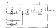
- the slip ratio calculator 21 receives the rotational speed detection values output from the speed detector 9, the speed detector 10, the speed detector 11, and the speed detector 12 as input, and the wheel 3 that is a drive wheel. And the slip ratio of the wheel 6 is calculated.
- the gain 29 outputs the rotation speed detection value of the wheel 3 by applying the gain given by the reciprocal of the gear ratio Gr of the gear 2 with the rotation speed of the electric motor 1 output from the speed detector 9 as an input value.
- the gain 30 outputs the wheel speed detection value of the wheel 3 by multiplying the radius R lr of the wheel 3 by using the rotation speed detection value of the wheel 3 output by the gain 29 as an input.
- the gain 31 outputs the wheel speed detection value of the wheel 7 by multiplying the radius R lf of the wheel 7 by using the rotation speed detection value of the wheel 7 output from the speed detector 11 as an input.
- the gain 32 outputs the rotation speed detection value of the wheel 6 by applying the gain given by the reciprocal of the gear ratio Gr of the gear 5 with the rotation speed detection value of the electric motor 4 output from the speed detector 10 as an input.
- the gain 33 outputs the wheel speed detection value of the wheel 6 by applying the radius R rr of the wheel 6 with the rotation speed detection value of the wheel 6 output by the gain 32 as an input.
- the gain 34 receives the rotation speed detection value of the wheel 8 output from the speed detector 12 and applies the radius R rf of the wheel 8 to output the wheel speed detection value of the wheel 8.
- the adder 35 inputs the wheel speed detection value of the wheel 7 and the wheel speed detection value of the wheel 8 and outputs the sum of them.
- the adder 36 receives the wheel speed detection value of the wheel 3 and the wheel speed detection value of the wheel 6 as inputs, and outputs the sum thereof.
- the gain 37 inputs the total value of the wheel speed detection values of the wheels 7 and 8 output from the adder 35, and outputs an average value of the wheel speed detection values of the wheels 7 and 8 by applying a gain of 0.5.
- the gain 38 receives the total value of the wheel speed detection values of the wheels 3 and 6 output from the adder 36 and outputs an average value of the wheel speed detection values of the wheels 3 and 6 by applying a gain of 0.5.
- the slip ratio calculator 21 receives the average value of the wheel speed detection values of the wheels 7 and 8 output from the gain 37 and the average value of the wheel speed detection values of the wheels 3 and 6 output from the gain 38 as the wheels 3. And the slip ratio of the wheel 6 is calculated.
- the average value of the wheel speed detection values of the wheels 7 and 8 is considered to represent the actual vehicle speed.
- the subtractor 39 receives the detected wheel speed value of the driving wheel and the detected wheel speed value of the driven wheel, and outputs the difference between them.
- the maximum value selector 40 receives the wheel speed detection value of the driving wheel and the wheel speed detection value of the driven wheel, and outputs the larger value.
- the divider 41 outputs the slip ratio by dividing the output of the subtractor 39 by the output of the maximum value selector 40.
- ⁇ represents the slip ratio of the drive wheel output from the slip ratio calculator 21
- V r represents the wheel speed of the drive wheel
- V represents the wheel speed of the driven wheel.
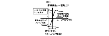
- FIG. 4 shows the relationship between the slip ratio ⁇ and the friction coefficient ⁇ between the wheel and the road surface.
- the fact that the friction coefficient ⁇ is in a negative region means that the force generated between the wheel and the road surface is opposite to the traveling direction of the vehicle.
- the value of the friction coefficient between the wheel and the road surface increases as the value of the slip ratio increases, so that the force acting between the wheel and the road surface also increases and no slip occurs. This is the same when the slip ratio becomes a negative value. Therefore, in FIG. 4, the slip does not occur in the region where the slip ratio ⁇ satisfies ⁇ 1 ⁇ ⁇ 2 .
- slip ratio value when the slip ratio value exceeds a certain range, the friction coefficient value between the wheel and the road surface decreases as the slip ratio value increases. appear.
- slip occurs in a region where the slip ratio ⁇ satisfies ⁇ > ⁇ 2 or ⁇ ⁇ 1 .
- the friction coefficient ⁇ is proportional to the driving force F of the driving wheel.
- slip control if the slip ratios ⁇ 1 and ⁇ 2 that change according to the road surface condition are searched for as a control target, and the slip ratio is controlled to be the searched value (that is, the rotational speed of the wheel is controlled).
- the maximum driving force during acceleration and the maximum braking force during deceleration are obtained.
- this control is referred to as “slip control”.
- the change in wheel speed when the drive wheel slip control is performed will be described.
- the case where the accelerator operation is performed will be described.
- the driving wheel rotates idly, and when the slip control is not performed, the wheel speed of the driving wheel becomes much higher than the wheel speed of the driven wheel.
- the rotation of the wheel is controlled so that the wheel speed of the driving wheel becomes close to the wheel speed of the driven wheel.
- FIG. 5 shows an example of the waveform of the wheel speed when the slip control of the driven wheel and the drive wheel during acceleration traveling is performed. Since (wheel wheel speed of the drive wheel) ⁇ (wheel speed of the driven wheel) always holds during the accelerator operation, the above-described equation (1) can be converted into the following equation. Accordingly, the value of the slip ratio ⁇ is always positive during the accelerator operation. When the accelerator operation is performed from a state in which the vehicle body is stopped or running, the slip ratio initially increases in the positive direction. However, if the slip determination unit 17 described later determines that the driving wheel is slipping, the driving is performed. In order to loosen the driving torque of the wheel, the wheel speed of the driving wheel shows a behavior approaching the wheel speed of the driven wheel.
- FIG. 6 shows a waveform example of the wheel speed when the slip control of the driven wheel and the driving wheel is performed at the time of the deceleration traveling. Since (wheel wheel speed of the driven wheel) ⁇ (wheel speed of the drive wheel) always holds during the brake operation, the above-described equation (1) can be converted into the following equation. Therefore, it can be seen that the value of the slip ratio ⁇ is always negative when the brake is operated. When the brake operation is performed while the vehicle body is running, the slip ratio initially increases in the negative direction, but when the slip determination device 17 described later determines that the drive wheel is slipping, the braking torque of the drive wheel is loosened. Therefore, the wheel speed of the driving wheel shows a behavior approaching the wheel speed of the driven wheel.
- the friction characteristic calculator 65 determines whether or not the driving wheel is slipping. When it is determined that the driving wheel is slipping, the friction characteristic calculator 65 searches for a slip rate control target (hereinafter referred to as “slip rate target value”), A torque reduction command is output to the torque command calculator 20 so that the searched slip ratio is obtained. In this case, there are a case where a torque reduction command is output so that one of the torques of the electric motor 1 and the electric motor 4 is reduced, and a case where a torque reduction command is output so that the torque output by both is reduced.
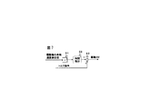
- FIG. 7 shows the configuration of the driving force calculator 19.
- the differentiator 52 outputs a product obtained by time-differentiating a value obtained by multiplying the wheel speed detection value of the driving wheel by the electric motor and the inertia 51 of the wheel.
- the subtractor 53 receives the torque command output from the torque command calculator 20 and the time differential value output from the differentiator 52 as inputs, and outputs the difference between them as a driving force F.
- FIG. 8 shows the configuration of the driving force gradient calculator 18.
- the driving force gradient calculator 18 calculates the gradient of the driving force with respect to the slip rate by calculating the time rate of change of each of the slip rate ⁇ and the driving force F in FIG.
- the pitching vibration frequency component removal filter 54 receives the driving force F output from the driving force calculator 19 and removes the pitching vibration frequency component included in the driving force F.
- the pitching vibration frequency of a dump truck is about 1 to 3 Hz. Therefore, for the filter 54, for example, a band-eliminate filter having a filter characteristic for dropping only a frequency band of about 1 to 3 Hz can be used. Note that a combination of a low pass filter and a high pass filter may be used instead of the band eliminate filter.
- the differentiator 55 receives the driving force F output from the pitching vibration frequency component removal filter 54 and outputs a time differential value dF / dt.
- the pitching vibration frequency component removal filter 56 receives the slip ratio ⁇ output from the slip ratio calculator 21 and removes the pitching vibration frequency component included in the slip ratio ⁇ .
- the filter 56 has the same characteristics as the filter 54.
- the differentiator 57 receives the slip ratio ⁇ output from the pitching vibration frequency component removal filter 56 and outputs a time differential value d ⁇ / dt.
- the divider 58 divides dF / dt output from the differentiator 55 by d ⁇ / dt output from the differentiator 57 to output a driving force gradient dF / d ⁇ with respect to the slip ratio.
- DF / d ⁇ has a positive value in the non-slip region and a negative value in the slip region both during acceleration traveling and during deceleration traveling. Therefore, the slip ratio at the moment when dF / d ⁇ changes from positive to negative is the slip ratio at which the driving force is maximized during acceleration traveling and the braking force is maximized during deceleration traveling.
- the slip determiner 17 determines that the driving wheel is not slipping and does not correct the torque command. Then, it is determined that the driving wheel is slipping at the moment when the value of dF / d ⁇ first changes from positive to negative, and a torque reduction command is output so that the slip ratio becomes the slip ratio at the time of slip determination. Correct the command.
- the slip determination method is not limited to the moment when dF / d ⁇ first changes from positive to negative. For example, the drive wheel slips at the moment when the value of dF / d ⁇ exceeds a predetermined threshold. May be determined.
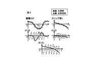
- FIG. 9 shows a comparison between the prior art and the first embodiment of the present invention with respect to the driving force F, slip ratio ⁇ , and time differential dF / dt, d ⁇ / dt, and dF / d ⁇ waveforms during deceleration traveling. .
- both dF / dt and d ⁇ / dt vibrate greatly in the positive and negative directions and dF / d ⁇ cannot be calculated correctly. For this reason, it is not possible to search for the slip ratio at which the braking force becomes maximum, and the slip ratio cannot be controlled to an appropriate slip ratio target value.
- the pitching vibration included in the driving force F and the slip ratio ⁇ is removed, noise is not included in each time differential waveform, and a correct dF / d ⁇ value can be output.
- dF / d ⁇ is correctly calculated and driven during acceleration traveling. It is possible to search for the slip ratio at which the braking force is maximum when the force is decelerated and to control the torque so that the searched slip ratio is obtained.
- a detection signal from a weight sensor (weight detector) 90 provided in the dump truck is input to the driving force gradient calculator 18 ′.
- the weight sensor 90 is for detecting the weight of the transported object loaded on the loading platform V.
- a sensor other than the weight sensor 90 may be used as long as it can detect the loading amount of the loading platform V.
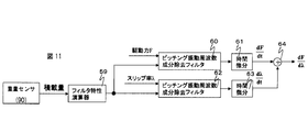
- FIG. 11 shows the configuration of the driving force gradient calculator 18 'when taking into account changes in the loading capacity.
- the filter characteristic calculator 59 calculates the pitching vibration frequency of the vehicle body using the load from the weight sensor 90 as an input.
- the pitching vibration frequency component removal filter 60 receives the driving force F and removes the pitching vibration frequency calculated by the filter characteristic calculator 59 from the driving force F.
- the differential calculator 61 receives the driving force F output from the pitching vibration frequency component removal filter 60 and outputs a time differential value dF / dt.
- the pitching vibration frequency component removal filter 62 receives the slip ratio ⁇ and removes the pitching vibration frequency calculated by the filter characteristic calculator 59 from the slip ratio ⁇ .
- the differential calculator 63 receives the slip ratio ⁇ output from the pitching vibration frequency component removal filter 62 and outputs a time differential value d ⁇ / dt.
- the divider 64 outputs dF / d ⁇ corresponding to the gradient of FIG. 4 by dividing dF / dt output from the differentiator 61 by d ⁇ / dt output from the differentiator 63.
- FIG. 10 shows the relationship between the loading amount and the pitching vibration frequency.
- FIG. 10 is a graph in which the natural frequency of the vehicle body is calculated from the equation of motion of the vehicle body to determine the pitching vibration frequency corresponding to the load, and this is plotted in a curve.
- Fig. 12 shows the vibration model of the car body.
- the vibration model shown in FIG. 12 is a simple model in which the vehicle body is divided into a sprung and unsprung state. If the pitch angle is ⁇ , the equation of motion of the vehicle body is expressed by the following equation.
- I y is the moment of inertia in the y-axis direction and is generally proportional to the load capacity.
- k f and k r are spring constants of the front and rear wheels, and l f and l r are distances in the x-axis direction from the center of gravity of the vehicle body to the front and rear wheels.
- the filter characteristic calculator 59 can calculate the pitching vibration frequency component corresponding to the load amount.
- the filter characteristic calculator 59 calculates the pitching vibration frequency of the vehicle body such that the larger the load value, the smaller the pitching vibration frequency of the vehicle body.
- the dump truck according to the modified example 1 removes the pitching vibration frequency component even when the pitching vibration frequency changes in accordance with the change in the loading capacity, and the driving force during acceleration traveling is the braking force during deceleration traveling. It is possible to search for the slip ratio that maximizes the torque and control the torque so that the searched slip ratio is obtained.
- a detection signal from a weight sensor (weight detector) 90 provided in the dump truck is input to the driving force gradient calculator 18 ''.
- the weight sensor 90 is for detecting the weight of the transported object loaded on the loading platform V.
- a sensor other than the weight sensor 90 may be used as long as it can detect the loading amount of the loading platform V.
- FIG. 13 shows the configuration of the driving force gradient calculator 18 ′′ when the change in the loading capacity is taken into consideration.
- the filter characteristic calculator 81 receives the loading amount from the weight sensor 90 as an input and selects the pitching vibration frequency of the vehicle body from predetermined numerical values.
- the filter characteristic calculator 81 determines whether or not the value of the loading amount of the loading platform V input from the weight sensor 90 is equal to or greater than a predetermined threshold value. Then, if the value of the load capacity is equal to or higher than the threshold is regarded as consignment in the carrier V are stacked, the filter characteristic calculator 81 outputs the pitching vibration frequency f l (first pitching vibration frequency) To do. On the other hand, when the value of the load amount is less than the threshold value, it is considered that no load is loaded on the loading platform V, and the filter characteristic calculator 81 outputs the pitching vibration frequency fe (second pitching vibration frequency). To do.
- the loading platform V is often either loaded with a full load or empty. This focuses on, in Modification 2, based on input from the filter characteristic calculator 81 weight sensor 90, the pitching vibration frequency f l in the case of there load, in the case of no load pitching vibration frequency f e Selective output.
- the pitching vibration frequency component removal filter 82 receives the driving force F and removes the pitching vibration frequency selected by the filter characteristic calculator 81 from the driving force F.
- the differential calculator 83 receives the driving force F output from the pitching vibration frequency component removal filter 82 and outputs a time differential value dF / dt.
- the pitching vibration frequency component removal filter 84 receives the slip ratio ⁇ and removes the pitching vibration frequency selected by the filter characteristic calculator 81 from the slip ratio ⁇ .
- the differential calculator 63 receives the slip ratio ⁇ output from the pitching vibration frequency component removal filter 62 and outputs a time differential value d ⁇ / dt.
- the divider 64 outputs dF / d ⁇ corresponding to the gradient of FIG. 4 by dividing dF / dt output from the differentiator 61 by d ⁇ / dt output from the differentiator 63.
- the dump truck according to the modified example 2 removes the pitching vibration frequency component even when the pitching vibration frequency changes in accordance with the change in the loading amount, and the driving force during acceleration traveling is the braking force during deceleration traveling. It is possible to search for the slip ratio that maximizes the torque and control the torque so that the searched slip ratio is obtained. Moreover, according to the modification 2, since the pitching vibration frequency output with the presence or absence of a conveyed product can be selected, there exists an advantage which can simplify control of the speed of a wheel.
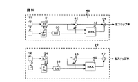
- Modification 3 has a configuration for separately calculating the slip ratio of the left wheel and the slip ratio of the right wheel.
- FIG. 14 shows the configuration of a slip ratio calculator according to the third modification.
- the slip ratio calculator 48 for the left wheel calculates the slip ratios of the wheel 3 that is the driving wheel and the wheel 7 that is the driven wheel, using the rotational speed detection values output from the speed detector 9 and the speed detector 11 as inputs.
- the gain 29 outputs the rotation speed detection value of the wheel 3 by applying the gain given by the reciprocal of the gear ratio Gr of the gear 2 with the rotation speed of the electric motor 1 output from the speed detector 9 as an input value.
- the gain 30 outputs the wheel speed detection value of the wheel 3 by multiplying the radius R lr of the wheel 3 by using the rotation speed detection value of the wheel 3 output by the gain 29 as an input.
- the gain 31 outputs the wheel speed detection value of the wheel 7 by multiplying the radius R lf of the wheel 7 by using the rotation speed detection value of the wheel 7 output from the speed detector 11 as an input.
- the wheel speed detection value of the wheel 7 is considered to represent the actual vehicle speed.
- the subtractor 42 receives the detected wheel speed value of the driving wheel and the detected wheel speed value of the driven wheel, and outputs the difference between them.
- the maximum value selector 43 receives the detected wheel speed value of the driving wheel and the detected wheel speed value of the driven wheel, and outputs the larger value.
- the divider 44 outputs the slip ratio of the left wheel by dividing the output of the subtractor 42 by the output of the maximum value selector 43. In addition, when the slip ratio of the output left wheel is expressed by an equation, the above-described equation (1) is obtained.
- the slip ratio calculator 49 for the right wheel receives the rotational speed detection values output from the speed detector 10 and the speed detector 12 as inputs, and calculates the slip ratio of the wheel 6 that is the driving wheel and the wheel 8 that is the driven wheel. Calculate.
- the gain 32 outputs the rotation speed detection value of the wheel 6 by applying the gain given by the reciprocal of the gear ratio Gr of the gear 5 with the rotation speed detection value of the electric motor 4 output from the speed detector 10 as an input.
- the gain 33 outputs the wheel speed detection value of the wheel 6 by applying the radius R rr of the wheel 6 with the rotation speed detection value of the wheel 6 output by the gain 32 as an input.
- the gain 34 outputs the wheel speed detection value of the wheel 8 by multiplying the radius R rf of the wheel 8 by using the rotation speed detection value of the wheel 8 output from the speed detector 12 as an input.
- the wheel speed detection value of the wheel 8 is considered to represent the actual vehicle speed.
- the subtracter 45 receives the detected wheel speed value of the driving wheel and the detected wheel speed value of the driven wheel, and outputs the difference between them.
- the maximum value selector 46 receives the wheel speed detection value of the driving wheel and the wheel speed detection value of the driven wheel, and outputs the larger value.
- the divider 47 divides the output of the subtractor 45 by the output of the maximum value selector 46 to output the slip ratio of the right wheel.
- the dump truck according to the modified example 3 can separately calculate the slip ratio of the left wheel and the slip ratio of the right wheel, and can control the torque of the drive wheels 3 and 6 independently. Therefore, the rotational speed of the wheel can be controlled with higher accuracy. Moreover, according to the modification 3, even if one of the speed detectors 9 and 10 for the left wheel or the speed detectors 11 and 12 for the right wheel breaks down, the slip ratio can be calculated. Even if the speed detector breaks down, the control of the rotational speed of the wheel can be continued.
- Modification 4 has a configuration for separately calculating the driving force of the left driving wheel and the driving force of the right driving wheel.
- FIG. 15 shows the configuration of the driving force calculator according to the fourth modification.
- the driving force calculator 72 is for calculating the driving force F of the left driving wheel.
- the differentiator 67 outputs a product obtained by time-differentiating a value obtained by multiplying the wheel speed detection value of the left driving wheel by the electric motor and the inertia 66 of the wheel.
- the subtractor 68 receives the torque command for the left driving wheel output from the torque command calculator 20 and the time differential value output from the differentiator 67 and outputs the difference between them as the driving force F for the left driving wheel.
- the driving force calculator 73 is for calculating the driving force F of the right driving wheel.
- the differentiator 70 outputs a product obtained by time-differentiating a value obtained by multiplying the wheel speed detection value of the right driving wheel by the electric motor and the inertia 69 of the wheel.
- the subtractor 71 receives the torque command of the right drive wheel output from the torque command calculator 20 and the time differential value output from the differentiator 70 as an input, and outputs the difference between them as the drive force F of the right drive wheel.
- the dump truck according to the modified example 4 can separately calculate the driving force of the left driving wheel and the driving force of the right driving wheel, and can control the torque of the driving wheels 3 and 6 independently on the left and right. . Therefore, the rotational speed of the wheel can be controlled with higher accuracy. Moreover, according to the modification 4, even if one of the speed detectors 9 and 10 for the left wheels or the speed detectors 11 and 12 for the right wheels breaks down, the driving force can be calculated. Even if the speed detector breaks down, the control of the rotational speed of the wheel can be continued.
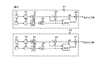
- FIG. 16 shows the configuration of the dump truck slip ratio calculator 79 according to the second embodiment.
- the slip ratio calculator 79 includes pitching vibrations for the wheel speed detection values of the wheels 3, 6, 7, and 8 output from the speed detectors 9, 10, 11, and 12, respectively.
- Frequency component removal filters 74, 75, 76, and 77 are installed. These pitching vibration frequency component removal filters 74, 75, 76 and 77 remove the pitching vibration frequency component included in the wheel speed detection value.
- the slip ratio calculator 79 receives the average value of the wheel speeds of the left and right driven wheels 7 and 8 and the drive wheels 3 and 6 from which the pitching vibration frequency component has been removed to obtain the slip ratio.
- the frequency component is removed by the filter.
- the pitching vibration frequency component removal filters 74, 75, 76, and 77 are band-eliminate filters having a filter characteristic that drops only the frequency band of about 1 to 3 Hz. This is because the pitching vibration frequency of the dump truck is about 1 to 3 Hz.
- a combination of a low-pass filter and a high-pass filter may be used instead of the band-eliminated filter.
- Modification 5" a detection signal from a weight sensor (weight detector) 90 provided in the dump truck is input to the slip ratio calculator 80.
- the weight sensor 90 is for detecting the weight of the transported object loaded on the loading platform V.
- a sensor other than the weight sensor 90 may be used as long as it can detect the loading amount of the loading platform V.
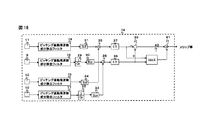
- FIG. 17 shows the configuration of the slip ratio calculator 80 when a change in the loading amount is taken into consideration.
- the filter characteristic calculator 78 receives the load amount from the weight sensor 90 and calculates the pitching vibration frequency of the vehicle body using the above-described equation (5).
- the filter characteristic calculator 78 calculates the pitching vibration frequency of the vehicle body so that the pitching vibration frequency of the vehicle body becomes smaller as the load value is larger.
- the pitching vibration frequency component removal filters 74, 75, 76, 77 remove the pitching vibration frequency component calculated by the filter characteristic calculator 78 from the detected wheel speed value.
- the slip ratio calculator 80 inputs the average value of the wheel speeds of the left and right driven wheels 7 and 8 and the drive wheels 3 and 6 from which the pitching vibration frequency component has been removed to obtain the slip ratio.
- the dump truck according to the modified example 5 removes the pitching vibration frequency component even when the pitching vibration frequency changes according to the change in the loading capacity, and the driving force during acceleration traveling is the braking force during deceleration traveling. It is possible to search for the slip ratio that maximizes the torque and control the torque so that the searched slip ratio is obtained.
- Modification 6 In Modification 6, a detection signal from a weight sensor (weight detector) 90 provided in the dump truck is input to the slip ratio calculator 88.
- the weight sensor 90 is for detecting the weight of the transported object loaded on the loading platform V.
- a sensor other than the weight sensor 90 may be used as long as it can detect the loading amount of the loading platform V.
- FIG. 18 shows a configuration of the slip ratio calculator 88 when a change in the loading amount is taken into consideration.
- the filter characteristic calculator 87 determines whether or not the value of the loading amount of the loading platform V input from the weight sensor 90 is equal to or greater than a predetermined threshold value. Then, if the value of the load capacity is equal to or higher than the threshold is regarded as consignment in the carrier V are stacked, the filter characteristic calculator 87 outputs the pitching vibration frequency f l (first pitching vibration frequency) To do. On the other hand, when the value of the load amount is less than the threshold value, it is considered that no load is loaded on the loading platform V, and the filter characteristic calculator 87 outputs the pitching vibration frequency fe (second pitching vibration frequency). To do.
- the filter characteristic calculator 87 selectively outputs the pitching vibration frequency fl or the pitching vibration frequency fe based on the input from the weight sensor 90.
- the pitching vibration frequency component removal filters 74, 75, 76, and 77 remove the pitching vibration frequency component selected by the filter characteristic calculator 78 from the detected wheel speed value.
- the slip ratio calculator 88 obtains the slip ratio by inputting the average value of the wheel speeds of the left and right driven wheels 7 and 8 and the drive wheels 3 and 6 from which the pitching vibration frequency component has been removed.
- the dump truck according to the modified example 6 removes the pitching vibration frequency component even when the pitching vibration frequency changes in accordance with the change in the loading capacity, and the driving force during acceleration traveling is the braking force during deceleration traveling. It is possible to search for the slip ratio that maximizes the torque and control the torque so that the searched slip ratio is obtained. Moreover, according to the modification 6, since the pitching vibration frequency output with the presence or absence of a conveyed product can be selected, there exists an advantage which can simplify control of the speed of a wheel.
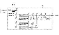
- the dump truck according to the second embodiment may be configured to separately calculate the slip ratio of the left wheel and the slip ratio of the right wheel.
- a pitching vibration frequency component removal filter 74 is installed between the speed detector 11 and the gain 31 of the slip ratio calculator 91 for the left wheel, and the speed detector 9 and the gain 29
- a pitching vibration frequency component removal filter 75 is installed between the two.
- a pitching vibration frequency component removal filter 76 is installed between the speed detector 12 and the gain 34 of the slip ratio calculator 92 for the right wheel, and the pitching vibration frequency component is removed between the speed detector 10 and the gain 32.
- a filter 77 is installed.
- the slip ratio calculator 91 calculates the slip ratio of the left wheel using the wheel speed detection value from which the pitching vibration frequency component has been removed by the pitching vibration frequency component removal filters 74 and 75. Similarly, the slip ratio calculator 92 calculates the slip ratio of the right wheel.
- the dump truck according to the modified example 7 can separately calculate the slip ratio of the left wheel and the slip ratio of the right wheel, and can control the torque of the drive wheels 3 and 6 independently. Therefore, the rotational speed of the wheel can be controlled with higher accuracy. Moreover, according to the modified example 7, even if one of the speed detectors 9 and 10 for the left wheels or the speed detectors 11 and 12 for the right wheels breaks down, the slip ratio can be calculated. Even if the speed detector breaks down, the control of the rotational speed of the wheel can be continued.
Landscapes
- Engineering & Computer Science (AREA)
- Power Engineering (AREA)
- Transportation (AREA)
- Mechanical Engineering (AREA)
- Life Sciences & Earth Sciences (AREA)
- Sustainable Development (AREA)
- Sustainable Energy (AREA)
- Electric Propulsion And Braking For Vehicles (AREA)
Description



変形例1では、ダンプトラックに設けられた重量センサ(重量検出器)90からの検出信号が駆動力勾配演算器18’に入力される。この重量センサ90は、荷台Vに積載されている運搬物の重量を検出するためのものである。なお、荷台Vの積載量を検出できるものであれば、重量センサ90以外のセンサを用いても良い。


数式(5)を用いることにより、フィルタ特性演算器59は、積載量に応じたピッチング振動周波数成分を演算することができる。なお、数式(5)によれば、分母にIyがあることから、積載量が大きいほど、車体の固有振動数fは小さくなることが分かる。即ち、フィルタ特性演算器59は、積載量の値が大きいほど車体のピッチング振動周波数が小さくなるように、車体のピッチング振動周波数を演算している。
変形例2では、ダンプトラックに設けられた重量センサ(重量検出器)90からの検出信号が駆動力勾配演算器18’’に入力される。この重量センサ90は、荷台Vに積載されている運搬物の重量を検出するためのものである。なお、荷台Vの積載量を検出できるものであれば、重量センサ90以外のセンサを用いても良い。
変形例3は、左側の車輪のスリップ率と右側の車輪のスリップ率を別々に演算する構成を備えている。その変形例3に係るスリップ率演算器の構成を図14に示す。
変形例4は、左側の駆動輪の駆動力と右側の駆動輪の駆動力を別々に演算する構成を備えている。その変形例4に係る駆動力演算器の構成を図15に示す。
続いて、本発明の第2実施例に係るダンプトラックについて図面を用いて説明する。なお、第1実施例におけるフィルタは、駆動力F及びスリップ率λに含まれるピッチング振動周波数成分を除去したのに対し、第2実施例におけるフィルタは、各車輪の車輪速度検出値に含まれるピッチング振動周波数成分を除去している点で相違する。別言すれば、第1実施例では、フィルタは駆動力勾配演算器に設けられていたが、第2実施例では、フィルタはスリップ率演算器に設けられている点で相違する。そこで、以下の説明は、この相違点を中心に説明することとし、第1実施例と同じ構成についての説明は省略する。なお、図中、第1実施例と同一符号のものは、同一の構成である。
変形例5では、ダンプトラックに設けられた重量センサ(重量検出器)90からの検出信号がスリップ率演算器80に入力される。この重量センサ90は、荷台Vに積載されている運搬物の重量を検出するためのものである。なお、荷台Vの積載量を検出できるものであれば、重量センサ90以外のセンサを用いても良い。
変形例6では、ダンプトラックに設けられた重量センサ(重量検出器)90からの検出信号がスリップ率演算器88に入力される。この重量センサ90は、荷台Vに積載されている運搬物の重量を検出するためのものである。なお、荷台Vの積載量を検出できるものであれば、重量センサ90以外のセンサを用いても良い。
第2実施例に係るダンプトラックにおいて、左側の車輪のスリップ率と右側の車輪のスリップ率を別々に演算する構成を備えても良い。この場合、図19に示すように、左側車輪用のスリップ率演算器91の速度検出器11とゲイン31との間にピッチング振動周波数成分除去フィルタ74を設置し、速度検出器9とゲイン29との間にピッチング振動周波数成分除去フィルタ75を設置する。また、右側車輪用のスリップ率演算器92の速度検出器12とゲイン34との間にピッチング振動周波数成分除去フィルタ76を設置し、速度検出器10とゲイン32との間にピッチング振動周波数成分除去フィルタ77を設置する。
Claims (14)
- 電動機と、前記電動機により駆動あるいは制動される駆動輪と、前記駆動輪の回転に従動する従動輪と、前記電動機を制御する電動機制御器と、前記駆動輪及び前記従動輪の車輪速度を検出する速度検出器と、を備えた電気駆動車両において、
前記電動機制御器は、
前記速度検出器により検出された車輪速度検出値から前記駆動輪のスリップ率を演算するスリップ率演算部と、
前記駆動輪のトルク指令を演算するトルク指令演算部と、
前記駆動輪の車輪速度検出値と前記駆動輪のトルク指令から前記駆動輪に発生する駆動力を演算する駆動力演算部と、
前記スリップ率及び前記駆動力に含まれる車体のピッチング振動周波数成分を低減するフィルタと、を有する
ことを特徴とする電気駆動車両。 - 請求項1において、
前記フィルタは、1~3Hz程度の前記車体のピッチング振動周波数成分を除去するフィルタ特性を有することを特徴とする電気駆動車両。 - 請求項1において、
運搬物の積載量を検出する重量検出器と、前記重量検出器にて検出された積載量の値に基づいて前記車体のピッチング振動周波数成分を演算するフィルタ特性演算部と、を更に備え、
前記フィルタは、前記フィルタ特性演算部で演算された前記車体のピッチング振動周波数成分を除去することを特徴とする電気駆動車両。 - 請求項3において、
前記フィルタ特性演算部は、前記積載量の値が大きいほど前記車体のピッチング振動周波数が小さくなるように、前記車体のピッチング振動周波数を演算することを特徴とする電気駆動車両。 - 請求項3において、
前記運搬物が積載されているか否かを判断するための閾値を予め定めておき、
前記重量検出器にて検出された積載量の値が前記閾値以上の場合には、前記フィルタ特性演算部は第1のピッチング振動周波数を出力し、前記重量検出器にて検出された積載量の値が前記閾値未満の場合には、前記フィルタ特性演算部は第2のピッチング振動周波数を出力するようにしたことを特徴とする電気駆動車両。 - 請求項1において、
前記フィルタにて前記車体のピッチング振動周波数成分が低減された前記スリップ率及び前記駆動力から、前記スリップ率に対する前記駆動力の勾配を演算する駆動力勾配演算部と、前記駆動力勾配演算部で演算した前記スリップ率に対する駆動力の勾配からスリップ判定を行うスリップ判定部と、を更に備えることを特徴とする電気駆動車両。 - 請求項6において、
前記スリップ判定部は、前記駆動力勾配演算部で前記スリップ率に対する前記駆動力の勾配が加速もしくは減速走行時に最初に正から負になった時に、前記駆動輪がスリップしていると判定することを特徴とする電気駆動車両。 - 請求項6において、
前記スリップ判定部は、前記駆動力勾配演算部で前記スリップ率に対する前記駆動力の勾配が、加速もしくは減速走行時に最初に所定の閾値を超えた時に前記駆動輪がスリップしていると判定することを特徴とする電気駆動車両。 - 請求項6において、
前記スリップ判定部がスリップ判定をした場合は、前記スリップ率が前記スリップ判定時の前記スリップ率になるように、前記トルク指令演算部は、前記トルク指令にトルク低減指令を加えることを特徴とする電気駆動車両。 - 電動機と、前記電動機により駆動あるいは制動される駆動輪と、前記駆動輪の回転に従動する従動輪と、前記電動機を制御する電動機制御器と、前記駆動輪及び前記従動輪の車輪速度を検出する速度検出器と、を備えた電気駆動車両において、
前記電動機制御器は、
前記速度検出器により検出された車輪速度検出値に含まれる車体のピッチング振動周波数成分を低減するフィルタと、
前記フィルタにて前記車体のピッチング振動周波数成分が低減された前記車輪速度検出値から前記駆動輪のスリップ率を演算するスリップ率演算部と、を有する
ことを特徴とする電気駆動車両。 - 請求項10において、
前記フィルタは、1~3Hz程度の前記車体のピッチング振動周波数成分を除去するフィルタ特性を有することを特徴とする電気駆動車両。 - 請求項10において、
運搬物の積載量を検出する重量検出器と、前記重量検出器にて検出された積載量の値に基づいて前記車体のピッチング振動周波数成分を演算するフィルタ特性演算部と、を更に備え、
前記フィルタは、前記フィルタ特性演算部で演算された前記車体のピッチング振動周波数成分を除去することを特徴とする電気駆動車両。 - 請求項12において、
前記フィルタ特性演算部は、前記積載量の値が大きいほど前記車体のピッチング振動周波数が小さくなるように、前記車体のピッチング振動周波数を演算することを特徴とする電気駆動車両。 - 請求項12において、
前記運搬物が積載されているか否かを判断するための閾値を予め定めておき、
前記重量検出器にて検出された積載量の値が前記閾値以上の場合には、前記フィルタ特性演算部は第1のピッチング振動周波数を出力し、前記重量検出器にて検出された積載量の値が前記閾値未満の場合には、前記フィルタ特性演算部は第2のピッチング振動周波数を出力するようにしたことを特徴とする電気駆動車両。
Priority Applications (3)
| Application Number | Priority Date | Filing Date | Title |
|---|---|---|---|
| AU2013250411A AU2013250411B2 (en) | 2012-04-20 | 2013-04-11 | Electric drive vehicle |
| DE112013002128.5T DE112013002128B4 (de) | 2012-04-20 | 2013-04-11 | Fahrzeug mit elektrischem Antrieb |
| US14/395,573 US9315116B2 (en) | 2012-04-20 | 2013-04-11 | Electric drive vehicle |
Applications Claiming Priority (2)
| Application Number | Priority Date | Filing Date | Title |
|---|---|---|---|
| JP2012096701A JP5824406B2 (ja) | 2012-04-20 | 2012-04-20 | 電気駆動車両 |
| JP2012-096701 | 2012-04-20 |
Publications (1)
| Publication Number | Publication Date |
|---|---|
| WO2013157484A1 true WO2013157484A1 (ja) | 2013-10-24 |
Family
ID=49383442
Family Applications (1)
| Application Number | Title | Priority Date | Filing Date |
|---|---|---|---|
| PCT/JP2013/060971 Ceased WO2013157484A1 (ja) | 2012-04-20 | 2013-04-11 | 電気駆動車両 |
Country Status (5)
| Country | Link |
|---|---|
| US (1) | US9315116B2 (ja) |
| JP (1) | JP5824406B2 (ja) |
| AU (1) | AU2013250411B2 (ja) |
| DE (1) | DE112013002128B4 (ja) |
| WO (1) | WO2013157484A1 (ja) |
Cited By (4)
| Publication number | Priority date | Publication date | Assignee | Title |
|---|---|---|---|---|
| DE102014203565A1 (de) * | 2014-02-27 | 2015-08-27 | Robert Bosch Gmbh | Steuereinrichtung und Verfahren zur Antriebsschlupfregelung für ein elektrisches Antriebssystem |
| CN107428260A (zh) * | 2015-03-27 | 2017-12-01 | 康奈可关精株式会社 | 电动车辆的驱动力控制装置 |
| CN108674254A (zh) * | 2018-05-11 | 2018-10-19 | 吉林大学 | 一种基于驱动能量在线优化的多轴驱动电动车辆车轮转矩分配方法 |
| CN111439254A (zh) * | 2018-12-28 | 2020-07-24 | 长沙智能驾驶研究院有限公司 | 动力半挂车控制方法、装置、控制设备和存储介质 |
Families Citing this family (16)
| Publication number | Priority date | Publication date | Assignee | Title |
|---|---|---|---|---|
| JP6167363B2 (ja) * | 2013-09-12 | 2017-07-26 | 日立オートモティブシステムズ株式会社 | 電動車両の制御装置及び電動車両の制御方法 |
| JP6183333B2 (ja) * | 2014-11-07 | 2017-08-23 | トヨタ自動車株式会社 | ハイブリッド自動車 |
| KR101865721B1 (ko) * | 2015-05-14 | 2018-06-08 | 현대자동차 주식회사 | 모터 토크 제어 장치 및 그 방법 |
| TW201710924A (zh) * | 2015-09-14 | 2017-03-16 | 義守大學 | 以多項式估測感應機參數之方法 |
| US10870356B2 (en) * | 2015-10-26 | 2020-12-22 | Mitsubishi Electric Corporation | Vehicle-speed control device |
| GB2550836A (en) * | 2016-03-22 | 2017-12-06 | Jaguar Land Rover Ltd | Controller and method |
| CN107539192B (zh) * | 2016-06-29 | 2019-08-13 | 比亚迪股份有限公司 | 一种电动矿山自卸车 |
| DE102016122245A1 (de) * | 2016-11-18 | 2018-05-24 | Dr. Ing. H.C. F. Porsche Aktiengesellschaft | Verfahren und Vorrichtung zur Traktionskontrolle für ein Fahrzeug |
| US10696313B2 (en) * | 2017-02-07 | 2020-06-30 | General Electric Company | Vehicle control system |
| JP7006532B2 (ja) * | 2018-08-06 | 2022-01-24 | トヨタ自動車株式会社 | トルク制御装置 |
| JP2020158001A (ja) * | 2019-03-27 | 2020-10-01 | アイシン精機株式会社 | 路面状態推定装置 |
| CN113386584A (zh) * | 2021-08-16 | 2021-09-14 | 达芬骑动力科技(北京)有限公司 | 车辆的防抱死控制方法、系统及电动车 |
| CN115675110A (zh) * | 2022-04-29 | 2023-02-03 | 一汽奔腾轿车有限公司 | 新能源汽车驱动电机扭矩过零时nvh电机控制方法 |
| US12311956B2 (en) * | 2022-05-27 | 2025-05-27 | Curtis Instruments, Inc. | Grade severity detection |
| JP2024139981A (ja) * | 2023-03-28 | 2024-10-10 | 日立建機株式会社 | 電動運搬車両及びその運行管制システム |
| JP2026067271A (ja) * | 2024-10-08 | 2026-04-20 | Astemo株式会社 | 車両制御装置、車両 |
Citations (3)
| Publication number | Priority date | Publication date | Assignee | Title |
|---|---|---|---|---|
| JP2002218605A (ja) * | 2000-11-14 | 2002-08-02 | Nissan Motor Co Ltd | 車両の駆動力制御装置 |
| JP2009077505A (ja) * | 2007-09-20 | 2009-04-09 | Hitachi Ltd | 電気駆動車両 |
| JP2011223691A (ja) * | 2010-04-06 | 2011-11-04 | Toyota Motor Corp | 車両制御装置 |
Family Cites Families (15)
| Publication number | Priority date | Publication date | Assignee | Title |
|---|---|---|---|---|
| DE3816166C2 (de) * | 1988-05-11 | 1996-06-20 | Bosch Gmbh Robert | Landwirtschaftlich nutzbare Zugmaschine mit angekoppeltem Arbeitsgerät |
| US5500798A (en) * | 1993-09-14 | 1996-03-19 | Toyota Jidosha Kabushiki Kaisha | Hydraulic active suspension controlled with side force compensation at respective vehicle wheels |
| US6371885B1 (en) * | 1999-04-01 | 2002-04-16 | Komatsu Ltd. | Working vehicle and vehicle speed control method thereof, variable power engine and power setting method thereof, and vehicle with variable power engine and power control method thereof |
| JP4356305B2 (ja) * | 2002-11-19 | 2009-11-04 | 株式会社デンソー | 車両制御装置 |
| US7337054B2 (en) * | 2004-07-29 | 2008-02-26 | Caterpillar Inc. | Systems and methods for controlling slip |
| US7416244B2 (en) * | 2006-03-06 | 2008-08-26 | Cnh America Llc | Vibration isolator with limited free movement |
| JP2007326404A (ja) * | 2006-06-06 | 2007-12-20 | Hitachi Constr Mach Co Ltd | 電気駆動ダンプトラックの駆動システム |
| JP2008091158A (ja) * | 2006-09-29 | 2008-04-17 | Seiko Epson Corp | 光源装置の製造方法、光源装置、およびプロジェクタ |
| US8144245B2 (en) * | 2007-02-28 | 2012-03-27 | Caterpillar Inc. | Method of determining a machine operation using virtual imaging |
| US20100094495A1 (en) * | 2007-03-05 | 2010-04-15 | Yokohama National University | Pitching control device of motor vehicle and control method |
| JP5103066B2 (ja) | 2007-06-21 | 2012-12-19 | 富士重工業株式会社 | 車両の路面状態推定装置 |
| JP5027933B2 (ja) * | 2009-01-08 | 2012-09-19 | 株式会社小松製作所 | トラクションコントロール装置 |
| JP5020388B2 (ja) * | 2009-01-08 | 2012-09-05 | 株式会社小松製作所 | 車両速度推定装置及びトラクションコントロール装置 |
| JP5455802B2 (ja) * | 2010-06-11 | 2014-03-26 | 日立建機株式会社 | 電動車両のピッチング制御装置 |
| US8548689B2 (en) * | 2010-11-23 | 2013-10-01 | Caterpillar Inc. | Implement induced machine pitch detection |
-
2012
- 2012-04-20 JP JP2012096701A patent/JP5824406B2/ja not_active Expired - Fee Related
-
2013
- 2013-04-11 WO PCT/JP2013/060971 patent/WO2013157484A1/ja not_active Ceased
- 2013-04-11 DE DE112013002128.5T patent/DE112013002128B4/de not_active Expired - Fee Related
- 2013-04-11 US US14/395,573 patent/US9315116B2/en active Active
- 2013-04-11 AU AU2013250411A patent/AU2013250411B2/en not_active Ceased
Patent Citations (3)
| Publication number | Priority date | Publication date | Assignee | Title |
|---|---|---|---|---|
| JP2002218605A (ja) * | 2000-11-14 | 2002-08-02 | Nissan Motor Co Ltd | 車両の駆動力制御装置 |
| JP2009077505A (ja) * | 2007-09-20 | 2009-04-09 | Hitachi Ltd | 電気駆動車両 |
| JP2011223691A (ja) * | 2010-04-06 | 2011-11-04 | Toyota Motor Corp | 車両制御装置 |
Cited By (7)
| Publication number | Priority date | Publication date | Assignee | Title |
|---|---|---|---|---|
| DE102014203565A1 (de) * | 2014-02-27 | 2015-08-27 | Robert Bosch Gmbh | Steuereinrichtung und Verfahren zur Antriebsschlupfregelung für ein elektrisches Antriebssystem |
| US10322648B2 (en) | 2014-02-27 | 2019-06-18 | Robert Bosch Gmbh | Control device and method for traction control for an electric drive system |
| EP3110651B1 (de) * | 2014-02-27 | 2022-11-09 | Robert Bosch GmbH | Steuereinrichtung und verfahren zur antriebsschlupfregelung für ein elektrisches antriebssystem |
| CN107428260A (zh) * | 2015-03-27 | 2017-12-01 | 康奈可关精株式会社 | 电动车辆的驱动力控制装置 |
| CN107428260B (zh) * | 2015-03-27 | 2020-03-10 | 康奈可关精株式会社 | 电动车辆的驱动力控制装置 |
| CN108674254A (zh) * | 2018-05-11 | 2018-10-19 | 吉林大学 | 一种基于驱动能量在线优化的多轴驱动电动车辆车轮转矩分配方法 |
| CN111439254A (zh) * | 2018-12-28 | 2020-07-24 | 长沙智能驾驶研究院有限公司 | 动力半挂车控制方法、装置、控制设备和存储介质 |
Also Published As
| Publication number | Publication date |
|---|---|
| US9315116B2 (en) | 2016-04-19 |
| US20150298577A1 (en) | 2015-10-22 |
| AU2013250411A1 (en) | 2014-11-06 |
| DE112013002128T5 (de) | 2014-12-31 |
| JP5824406B2 (ja) | 2015-11-25 |
| JP2013225975A (ja) | 2013-10-31 |
| DE112013002128B4 (de) | 2021-04-29 |
| AU2013250411B2 (en) | 2015-09-03 |
Similar Documents
| Publication | Publication Date | Title |
|---|---|---|
| JP5824406B2 (ja) | 電気駆動車両 | |
| EP3251888B1 (en) | Control device for electric vehicle and control method for electric vehicle | |
| US10266069B2 (en) | Control device for electric motor vehicle and control method for electric motor vehicle | |
| CN105980197B (zh) | 制动距离抑制装置 | |
| CN107848423B (zh) | 电动车辆的控制装置以及电动车辆的控制方法 | |
| EP3251906B1 (en) | Vehicle control device and vehicle control method | |
| JP6223717B2 (ja) | 電気自動車のスリップ制御装置 | |
| EP3093185A1 (en) | Control device for electric-powered vehicle and control method for electric-powered vehicle | |
| CN103209858B (zh) | 电驱动车辆 | |
| JP6440971B2 (ja) | 左右独立駆動車のトラクション制御機能付き駆動制御装置 | |
| KR20170140355A (ko) | 전동 차량의 제어 장치 및 전동 차량의 제어 방법 | |
| JP2004224172A (ja) | 横加速度センサのドリフト量推定装置、横加速度センサの出力補正装置及び路面摩擦状態推定装置 | |
| JP5994192B2 (ja) | トラクション制御装置及びトラクション制御方法 | |
| JP6266652B2 (ja) | トラクション制御装置及びトラクション制御方法 | |
| JP6096283B2 (ja) | トラクション制御装置及びトラクション制御方法 | |
| JP6880675B2 (ja) | 電動車両の制御方法、及び、電動車両の制御装置 | |
| JP2009077505A (ja) | 電気駆動車両 | |
| JP7169461B2 (ja) | 制御装置 | |
| JP5889736B2 (ja) | ブレーキ制御装置 | |
| JP6764292B2 (ja) | 滑り抑制制御装置 | |
| JP4686774B2 (ja) | 電動車両の制御装置 | |
| JP2025062854A (ja) | 運搬車両及び管制システム | |
| CN119502713A (zh) | 用于电动车辆的牵引力控制方法和装置 | |
| WO2014155700A1 (ja) | 鉱山用ダンプトラックおよびその運行診断方法 |
Legal Events
| Date | Code | Title | Description |
|---|---|---|---|
| 121 | Ep: the epo has been informed by wipo that ep was designated in this application |
Ref document number: 13778594 Country of ref document: EP Kind code of ref document: A1 |
|
| WWE | Wipo information: entry into national phase |
Ref document number: 14395573 Country of ref document: US Ref document number: 1120130021285 Country of ref document: DE Ref document number: 112013002128 Country of ref document: DE |
|
| ENP | Entry into the national phase |
Ref document number: 2013250411 Country of ref document: AU Date of ref document: 20130411 Kind code of ref document: A |
|
| 122 | Ep: pct application non-entry in european phase |
Ref document number: 13778594 Country of ref document: EP Kind code of ref document: A1 |