WO2013157401A1 - 空気調和機 - Google Patents
空気調和機 Download PDFInfo
- Publication number
- WO2013157401A1 WO2013157401A1 PCT/JP2013/060348 JP2013060348W WO2013157401A1 WO 2013157401 A1 WO2013157401 A1 WO 2013157401A1 JP 2013060348 W JP2013060348 W JP 2013060348W WO 2013157401 A1 WO2013157401 A1 WO 2013157401A1
- Authority
- WO
- WIPO (PCT)
- Prior art keywords
- heat exchanger
- auxiliary heat
- evaporation
- air conditioner
- indoor
- Prior art date
Links
Images


Classifications
-
- F—MECHANICAL ENGINEERING; LIGHTING; HEATING; WEAPONS; BLASTING
- F24—HEATING; RANGES; VENTILATING
- F24F—AIR-CONDITIONING; AIR-HUMIDIFICATION; VENTILATION; USE OF AIR CURRENTS FOR SCREENING
- F24F13/00—Details common to, or for air-conditioning, air-humidification, ventilation or use of air currents for screening
- F24F13/30—Arrangement or mounting of heat-exchangers
-
- F—MECHANICAL ENGINEERING; LIGHTING; HEATING; WEAPONS; BLASTING
- F24—HEATING; RANGES; VENTILATING
- F24F—AIR-CONDITIONING; AIR-HUMIDIFICATION; VENTILATION; USE OF AIR CURRENTS FOR SCREENING
- F24F1/00—Room units for air-conditioning, e.g. separate or self-contained units or units receiving primary air from a central station
- F24F1/0007—Indoor units, e.g. fan coil units
- F24F1/0059—Indoor units, e.g. fan coil units characterised by heat exchangers
- F24F1/0063—Indoor units, e.g. fan coil units characterised by heat exchangers by the mounting or arrangement of the heat exchangers
-
- F—MECHANICAL ENGINEERING; LIGHTING; HEATING; WEAPONS; BLASTING
- F24—HEATING; RANGES; VENTILATING
- F24F—AIR-CONDITIONING; AIR-HUMIDIFICATION; VENTILATION; USE OF AIR CURRENTS FOR SCREENING
- F24F1/00—Room units for air-conditioning, e.g. separate or self-contained units or units receiving primary air from a central station
- F24F1/0007—Indoor units, e.g. fan coil units
- F24F1/0083—Indoor units, e.g. fan coil units with dehumidification means
-
- F—MECHANICAL ENGINEERING; LIGHTING; HEATING; WEAPONS; BLASTING
- F24—HEATING; RANGES; VENTILATING
- F24F—AIR-CONDITIONING; AIR-HUMIDIFICATION; VENTILATION; USE OF AIR CURRENTS FOR SCREENING
- F24F11/00—Control or safety arrangements
- F24F11/89—Arrangement or mounting of control or safety devices
-
- F—MECHANICAL ENGINEERING; LIGHTING; HEATING; WEAPONS; BLASTING
- F24—HEATING; RANGES; VENTILATING
- F24F—AIR-CONDITIONING; AIR-HUMIDIFICATION; VENTILATION; USE OF AIR CURRENTS FOR SCREENING
- F24F3/00—Air-conditioning systems in which conditioned primary air is supplied from one or more central stations to distributing units in the rooms or spaces where it may receive secondary treatment; Apparatus specially designed for such systems
- F24F3/12—Air-conditioning systems in which conditioned primary air is supplied from one or more central stations to distributing units in the rooms or spaces where it may receive secondary treatment; Apparatus specially designed for such systems characterised by the treatment of the air otherwise than by heating and cooling
- F24F3/14—Air-conditioning systems in which conditioned primary air is supplied from one or more central stations to distributing units in the rooms or spaces where it may receive secondary treatment; Apparatus specially designed for such systems characterised by the treatment of the air otherwise than by heating and cooling by humidification; by dehumidification
-
- F—MECHANICAL ENGINEERING; LIGHTING; HEATING; WEAPONS; BLASTING
- F25—REFRIGERATION OR COOLING; COMBINED HEATING AND REFRIGERATION SYSTEMS; HEAT PUMP SYSTEMS; MANUFACTURE OR STORAGE OF ICE; LIQUEFACTION SOLIDIFICATION OF GASES
- F25B—REFRIGERATION MACHINES, PLANTS OR SYSTEMS; COMBINED HEATING AND REFRIGERATION SYSTEMS; HEAT PUMP SYSTEMS
- F25B13/00—Compression machines, plants or systems, with reversible cycle
-
- F—MECHANICAL ENGINEERING; LIGHTING; HEATING; WEAPONS; BLASTING
- F25—REFRIGERATION OR COOLING; COMBINED HEATING AND REFRIGERATION SYSTEMS; HEAT PUMP SYSTEMS; MANUFACTURE OR STORAGE OF ICE; LIQUEFACTION SOLIDIFICATION OF GASES
- F25B—REFRIGERATION MACHINES, PLANTS OR SYSTEMS; COMBINED HEATING AND REFRIGERATION SYSTEMS; HEAT PUMP SYSTEMS
- F25B40/00—Subcoolers, desuperheaters or superheaters
- F25B40/02—Subcoolers
-
- F—MECHANICAL ENGINEERING; LIGHTING; HEATING; WEAPONS; BLASTING
- F24—HEATING; RANGES; VENTILATING
- F24F—AIR-CONDITIONING; AIR-HUMIDIFICATION; VENTILATION; USE OF AIR CURRENTS FOR SCREENING
- F24F2140/00—Control inputs relating to system states
- F24F2140/20—Heat-exchange fluid temperature
-
- F—MECHANICAL ENGINEERING; LIGHTING; HEATING; WEAPONS; BLASTING
- F25—REFRIGERATION OR COOLING; COMBINED HEATING AND REFRIGERATION SYSTEMS; HEAT PUMP SYSTEMS; MANUFACTURE OR STORAGE OF ICE; LIQUEFACTION SOLIDIFICATION OF GASES
- F25B—REFRIGERATION MACHINES, PLANTS OR SYSTEMS; COMBINED HEATING AND REFRIGERATION SYSTEMS; HEAT PUMP SYSTEMS
- F25B2313/00—Compression machines, plants or systems with reversible cycle not otherwise provided for
- F25B2313/023—Compression machines, plants or systems with reversible cycle not otherwise provided for using multiple indoor units
- F25B2313/0234—Compression machines, plants or systems with reversible cycle not otherwise provided for using multiple indoor units in series arrangements
-
- F—MECHANICAL ENGINEERING; LIGHTING; HEATING; WEAPONS; BLASTING
- F25—REFRIGERATION OR COOLING; COMBINED HEATING AND REFRIGERATION SYSTEMS; HEAT PUMP SYSTEMS; MANUFACTURE OR STORAGE OF ICE; LIQUEFACTION SOLIDIFICATION OF GASES
- F25B—REFRIGERATION MACHINES, PLANTS OR SYSTEMS; COMBINED HEATING AND REFRIGERATION SYSTEMS; HEAT PUMP SYSTEMS
- F25B2313/00—Compression machines, plants or systems with reversible cycle not otherwise provided for
- F25B2313/031—Sensor arrangements
- F25B2313/0314—Temperature sensors near the indoor heat exchanger
Definitions
- the present invention relates to an air conditioner capable of performing a dehumidifying operation.
- an auxiliary heat exchanger is arranged on the back side of the main heat exchanger, and the refrigerant is evaporated only by the auxiliary heat exchanger to perform dehumidification locally, so that the load is reduced (compression)
- the evaporation region is limited to the auxiliary heat exchanger, and the temperature sensor is disposed downstream of the evaporation region, and is controlled to have a certain degree of superheat.
- an object of the present invention is to provide an air conditioner that can be used as both a sensor that detects the completion of evaporation of a liquid refrigerant and a sensor that detects a condensation temperature or an evaporation temperature in an air conditioning operation. .
- An air conditioner includes a refrigerant circuit in which a compressor, an outdoor heat exchanger, an expansion valve, and an indoor heat exchanger are connected.
- An auxiliary heat exchanger disposed on the windward side and supplied with liquid refrigerant; and a main heat exchanger disposed on the leeward side of the auxiliary heat exchanger, and during the dehumidifying operation, the auxiliary heat exchanger includes:
- the temperature detecting means has an evaporation area where the liquid refrigerant evaporates and a superheat area downstream of the evaporation area, and the temperature detection means for detecting that the evaporation of the liquid refrigerant is completed in the auxiliary heat exchanger, It arrange
- the air conditioner according to a second aspect of the invention is characterized in that, in the air conditioner according to the first aspect of the invention, the temperature detecting means is disposed near the center of the refrigerant path in the indoor heat exchanger.
- this air conditioner it is possible to detect the condensing temperature or the evaporating temperature in the cooling / heating operation by temperature detecting means for detecting that the evaporation of the liquid refrigerant is completed in the auxiliary heat exchanger during the dehumidifying operation.
- the liquid inlet in the auxiliary heat exchanger is below, and the temperature detecting means is the auxiliary heat exchanger. It is arranged near the upper end of.
- This air conditioner can increase the range of the evaporation zone of the auxiliary heat exchanger.
- An air conditioner according to a fourth invention is the air conditioner according to any one of the first to third inventions, wherein the main heat exchanger is disposed on the front side in the indoor unit; A back heat exchanger disposed on the back side in the indoor unit, and the auxiliary heat exchanger is disposed in front of the front heat exchanger.
- the air that has flowed through the superheated area is hardly cooled. Therefore, by detecting the temperature of the refrigerant circuit on the leeward side of the auxiliary heat exchanger, it is possible to detect that overheating is present at the outlet of the auxiliary heat exchanger. Moreover, there is no overcooling during the heating operation or erroneous detection of the temperature due to pressure loss during the cooling operation, and the operation does not become unstable.
- the temperature detecting means for detecting the evaporation of the liquid refrigerant in the auxiliary heat exchanger during the dehumidifying operation.
- the range of the evaporation region of the auxiliary heat exchanger can be increased.
- the area of the auxiliary heat exchanger can be increased, the range of the evaporation region of the auxiliary heat exchanger can be increased.
- the air conditioner 1 of this embodiment includes an indoor unit 2 installed indoors and an outdoor unit 3 installed outdoor.
- the air conditioner 1 includes a refrigerant circuit in which a compressor 10, a four-way valve 11, an outdoor heat exchanger 12, an expansion valve 13, and an indoor heat exchanger 14 are connected.
- an outdoor heat exchanger 12 is connected to the discharge port of the compressor 10 via a four-way valve 11, and an expansion valve 13 is connected to the outdoor heat exchanger 12.
- One end of the indoor heat exchanger 14 is connected to the expansion valve 13, and the suction port of the compressor 10 is connected to the other end of the indoor heat exchanger 14 via the four-way valve 11.
- the indoor heat exchanger 14 has an auxiliary heat exchanger 20 and a main heat exchanger 21.
- the air conditioner 1 can be operated in a cooling operation mode, a predetermined dehumidifying operation mode, and a heating operation mode.
- the remote controller selects one of the operations by a remote controller and performs an operation start operation, an operation switching operation or an operation. Stop operation can be performed. Further, the remote controller can change the air volume of the indoor unit 2 by setting a set temperature of the indoor temperature or changing the rotation speed of the indoor fan.
- the refrigerant discharged from the compressor 10 flows from the four-way valve 11 to the outdoor heat exchanger 12, the expansion valve 13, the auxiliary heat exchanger 20, the main heat, as indicated by the solid arrows in the figure.
- a cooling cycle or a dehumidification cycle is formed in which the refrigerant flows in sequence to the exchanger 21 and the refrigerant that has passed through the main heat exchanger 21 returns to the compressor 10 through the four-way valve 11. That is, the outdoor heat exchanger 12 functions as a condenser, and the indoor heat exchanger 14 (auxiliary heat exchanger 20 and main heat exchanger 21) functions as an evaporator.
- the refrigerant discharged from the compressor 10 is transferred from the four-way valve 11 to the main heat exchanger 21, the auxiliary heat exchanger 20, and the expansion, as indicated by broken arrows in the figure.
- a heating cycle is formed in which the refrigerant flows in order to the valve 13 and the outdoor heat exchanger 12, and the refrigerant that has passed through the outdoor heat exchanger 12 returns to the compressor 10 through the four-way valve 11. That is, the indoor heat exchanger 14 (auxiliary heat exchanger 20 and main heat exchanger 21) functions as a condenser, and the outdoor heat exchanger 12 functions as an evaporator.
- the indoor unit 2 has an air inlet 2a for indoor air on the upper surface, and an air outlet 2b for air conditioning air at the lower front surface.
- An air flow path is formed in the indoor unit 2 from the suction port 2a toward the blowout port 2b, and an indoor heat exchanger 14 and a cross-flow type indoor fan 16 are disposed in the air flow path. Therefore, when the indoor fan 16 rotates, room air is sucked into the indoor unit 1 from the suction port 2a.
- the intake air from the intake port 2 a flows to the indoor fan 16 side through the auxiliary heat exchanger 20 and the main heat exchanger 21.
- the intake air from the intake port 2 a flows through the main heat exchanger 21 to the indoor fan 16 side.
- the main heat exchanger 21 has a front heat exchanger 21 a disposed on the front side of the indoor unit 2 and a back heat exchanger 21 b disposed on the back side of the indoor unit 2, and this heat exchanger 21 a and 21 b are arranged in an inverted V shape so as to surround the indoor fan 16.
- the auxiliary heat exchanger 20 is arrange
- the auxiliary heat exchanger 20 and the main heat exchanger 21 each include a heat exchange pipe and a large number of fins.
- the liquid refrigerant is supplied from the liquid inlet 17a arranged near the lower end of the auxiliary heat exchanger 20, and the supplied liquid refrigerant is And flows so as to approach the upper end of the auxiliary heat exchanger 20. And it flows out from the exit 17b arrange
- the refrigerant branched in the branching portion 18a is supplied from the three inlets 17c of the main heat exchanger 21 to the lower and upper parts of the front heat exchanger 21a and the rear heat exchanger 21b, and then from the outlet 17d. It flows out and joins at the junction 18b.
- the refrigerant flows in the direction opposite to the above.
- the liquid refrigerant supplied from the liquid inlet 17 a of the auxiliary heat exchanger 20 is evaporated in the middle of the auxiliary heat exchanger 20. To do. Therefore, only a part of the auxiliary heat exchanger 20 near the liquid inlet 17a is an evaporation region where the liquid refrigerant evaporates. Therefore, when operating in the predetermined dehumidifying operation mode, in the indoor heat exchanger 14, only a part of the upstream side of the auxiliary heat exchanger 20 is an evaporation region and is downstream of the evaporation region of the auxiliary heat exchanger 20. Both the range on the side and the main heat exchanger 21 are overheated regions.
- the refrigerant that has flowed through the superheated region near the upper end of the auxiliary heat exchanger 20 flows through the lower part of the front heat exchanger 21 a disposed on the leeward side of the lower part of the auxiliary heat exchanger 20. Therefore, in the suction air from the suction port 2a, the air cooled in the evaporation region of the auxiliary heat exchanger 20 is heated by the front heat exchanger 21a and then blown out from the blower outlet 2b.
- the air that has flowed through the superheated area of the auxiliary heat exchanger 20 and the front heat exchanger 21a and the air that has flowed through the back heat exchanger 21b are substantially the same as the room temperature. And it blows out from the blower outlet 2b.
- an evaporation temperature sensor 30 that detects the evaporation temperature on the downstream side of the expansion valve 13 in the refrigerant circuit is attached to the outdoor unit 3. Then, the indoor unit 2 detects the indoor temperature sensor 31 that detects the indoor temperature (the temperature of the intake air from the suction port 2a of the indoor unit 2), and the auxiliary heat exchanger 20 detects that the evaporation of the liquid refrigerant has ended. An indoor heat exchanger temperature sensor 32 is attached.
- the indoor heat exchanger temperature sensor 32 is disposed on the leeward side near the upper end of the auxiliary heat exchanger 20, as shown in FIG. And in the superheat zone near the upper end of the auxiliary heat exchanger 20, the suction air from the suction inlet 2a is hardly cooled. Therefore, when the temperature detected by the indoor heat exchanger temperature sensor 32 is substantially the same as the indoor temperature detected by the indoor temperature sensor 31, the evaporation ends in the middle of the auxiliary heat exchanger 20, and the auxiliary heat It can be detected that the range near the upper end of the exchanger 20 is an overheated region.
- the indoor heat exchanger temperature sensor 32 is disposed in a heat transfer tube in an intermediate portion of the indoor heat exchanger 14. Therefore, the condensation temperature or evaporation temperature in the cooling / heating operation can be detected near the middle portion of the indoor heat exchanger 14.
- the control unit of the air conditioner 1 includes a compressor 10, a four-way valve 11, an expansion valve 13, a motor 16 a that drives an indoor fan 16, an evaporation temperature sensor 30, and an indoor temperature sensor. 31 and the indoor heat exchanger temperature sensor 32 are connected. Therefore, the control unit controls the command from the remote controller (operation start operation, set temperature of the room temperature, etc.), the evaporation temperature detected by the evaporation temperature sensor 30, the room temperature detected by the room temperature sensor 31 (the temperature of the intake air) ), The operation of the air conditioner 1 is controlled based on the intermediate heat exchange temperature detected by the indoor heat exchange temperature sensor 32.
- the auxiliary heat exchanger 20 in the predetermined dehumidifying operation mode, has an evaporation region where the liquid refrigerant evaporates and a superheat region downstream of the evaporation region.
- the compressor 10 and the expansion valve 13 are controlled so as to change according to the above.
- changing according to the load means changing according to the amount of heat supplied to the evaporation region, and the amount of heat is determined by, for example, the room temperature (the temperature of the intake air) and the room air volume.
- the load corresponds to the necessary dehumidifying capacity (necessary cooling capacity) and can be detected based on, for example, the difference between the room temperature and the set temperature.
- the compressor 10 is controlled based on the difference between the room temperature and the set temperature.
- the frequency of the compressor 10 is increased because the load is large when the difference between the room temperature and the set temperature is large, and the load is small when the difference between the room temperature and the set temperature is small. Controlled to decrease.
- the expansion valve 13 is controlled based on the evaporation temperature detected by the evaporation temperature sensor 30. As described above, when the frequency of the compressor 10 is controlled, the expansion valve 13 is set so that the evaporation temperature becomes a temperature within a predetermined range (10 ° C.-14 ° C.) near the target evaporation temperature (12 ° C.). Be controlled.
- the predetermined range of the evaporation temperature is preferably controlled to be constant regardless of the frequency of the compressor 10. However, even if it slightly changes depending on the frequency, there is no problem as long as it is substantially constant.
- the range of the evaporation region of the auxiliary heat exchanger 20 is changed, and the evaporation temperature is within the predetermined range.
- the auxiliary heat exchanger 20 and the front heat exchanger 21a each have 12 stages of heat transfer tubes. And when the number of stages used as the evaporation region of the auxiliary heat exchanger 20 in the predetermined dehumidifying operation mode is half or more of the number of stages of the front heat exchanger 21a, the range of the evaporation region of the auxiliary heat exchanger can be sufficiently widened. Sufficiently respond to load fluctuations. This is particularly effective when the load is large.
- FIG. 5 shows a change in flow rate when the opening degree of the expansion valve 13 is changed.
- the opening of the expansion valve 13 changes continuously according to the number of input drive pulses. And as the opening degree decreases, the flow rate of the refrigerant flowing through the expansion valve 13 decreases.
- the expansion valve 13 is in a fully closed state at the opening t0, and between the opening t0 and t1, the flow rate increases according to the first slope as the opening increases, and the opening t1 to t2 In between, the flow rate increases according to the second slope as the opening degree increases.
- the first slope is larger than the second slope.
- the frequency of the compressor 10 is decreased and the opening degree of the expansion valve 13 is decreased. Is changed small. Therefore, even if the range of the evaporation area of the auxiliary heat exchanger 20 is smaller than the predetermined area and the air volume sucked into the indoor unit 2 is constant, the air volume that actually passes through the evaporation area decreases.
- the indoor heat exchanger temperature sensor 32 is arrange
- the auxiliary heat since the liquid inlet 17a in the auxiliary heat exchanger 20 is located below and the indoor heat exchanger temperature sensor 32 is disposed near the upper end of the auxiliary heat exchanger 20, the auxiliary heat The range of the evaporation region of the exchanger 20 can be increased.
- the main heat exchanger 21 includes the front heat exchanger 21 a disposed on the front side in the indoor unit 2 and the back heat disposed on the back side in the indoor unit 2. Since the auxiliary heat exchanger 20 is arranged in front of the front heat exchanger 21a and the area of the auxiliary heat exchanger 20 can be increased, the evaporation area of the auxiliary heat exchanger 20 is increased. The range to change can be enlarged.
- the auxiliary heat exchanger and the main heat exchanger may be configured integrally. Therefore, in this case, the indoor heat exchanger is integrally configured, a portion corresponding to the auxiliary heat exchanger is provided on the uppermost wind side of the indoor heat exchanger, and a portion corresponding to the main heat exchanger is provided on the leeward side thereof. Is provided.
- the air conditioner that operates in the cooling operation mode, the predetermined dehumidifying operation mode, and the heating operation mode has been described.
- the dehumidifying operation that performs the dehumidifying operation by another method of the predetermined dehumidifying operation mode is described.
- An air conditioner that operates in the mode may be used.
- a sensor for detecting the end of evaporation of the liquid refrigerant and a sensor for detecting the condensation temperature or the evaporation temperature in the air conditioning operation can be used.
Landscapes
- Engineering & Computer Science (AREA)
- Mechanical Engineering (AREA)
- General Engineering & Computer Science (AREA)
- Chemical & Material Sciences (AREA)
- Combustion & Propulsion (AREA)
- Physics & Mathematics (AREA)
- Thermal Sciences (AREA)
- Air Conditioning Control Device (AREA)
- Air Filters, Heat-Exchange Apparatuses, And Housings Of Air-Conditioning Units (AREA)
Abstract
液冷媒の蒸発が終了したことを検知するセンサの他に、冷暖房運転での凝縮温度または蒸発温度を検知するためのセンサを配置する必要がある。 本発明の空気調和機では、室内熱交換器が、補助熱交換器20と、補助熱交換器20の風下側に配置された主熱交換器21とを有している。所定の除湿運転モードでの運転が行われているとき、補助熱交換器20に供給された液冷媒は、補助熱交換器20の途中で全て蒸発する。したがって、補助熱交換器20の上流側の一部だけが蒸発域であって、補助熱交換器20の蒸発域の下流側の範囲は過熱域である。そして、補助熱交換器20の過熱域の風下側であって、室内熱交換器の中間部近くに、室内熱交温度センサ32が配置される。
Description
本発明は、除湿運転を行うことができる空気調和機に関するものである。
従来の空気調和機には、主熱交換器の背面側に補助熱交換器を配置して、補助熱交換器だけで冷媒を蒸発させて局所的に除湿を行うことで、低負荷時(圧縮機の回転数が低いとき)、例えば、室温と設定温度との差が十分に小さく必要な冷却能力が小さいときでも除湿ができるようにした空気調和機がある。この空気調和機では、蒸発域を補助熱交換器に限定し、温度センサをその蒸発域の下流側に配置し、一定の過熱度となるように制御していた。
この空気調和機において、蒸発が完了していることを検知するための温度センサを、補助熱交換器の出口付近に設けた場合、室内熱交換器の液側寄りとなってしまう。これにより、冷房での高負荷運転時には、冷媒に圧力損失が付くため、熱交換器の蒸発温度としては高めの温度を誤検知してしまう。また、暖房運転時には、過冷却が付くため、実際の凝縮温度よりも低い温度が誤検知され、圧縮機に液が戻って、圧縮機の信頼性を損なう。
これを回避するためには、別途、冷暖房運転での凝縮温度または蒸発温度を検知するためのセンサが必要になり、コストがかかるという問題がある。
そこで、本発明の目的は、液冷媒の蒸発が終了したことを検知するセンサと、冷暖房運転での凝縮温度または蒸発温度を検知するためのセンサとを兼用できる空気調和機を提供することである。
第1の発明にかかる空気調和機は、圧縮機と、室外熱交換器と、膨張弁と、室内熱交換器とを接続した冷媒回路を備え、前記室内熱交換器が、除湿運転時に、最風上側に配置され且つ液冷媒が供給される補助熱交換器と、前記補助熱交換器の風下側に配置された主熱交換器とを有し、除湿運転時において、前記補助熱交換器は液冷媒が蒸発する蒸発域と前記蒸発域の下流側の過熱域を有しており、前記補助熱交換器において液冷媒の蒸発が終了していることを検知するための温度検知手段が、前記補助熱交換器の下流側に配置されることを特徴とする。
この空気調和機では、除湿運転時において、補助熱交換器の出口で十分に過熱が付いている場合には、その過熱域を流れた空気は、ほとんど冷却されないため、風下側の伝熱管を冷やさないので、補助熱交換器の風下側の冷媒回路の温度を検知することで、補助熱交換器の出口で過熱が付いていることを検出できる。また、暖房運転時に過冷却が付いたり、冷房運転時の圧損で、温度を誤検知して、運転が不安定になることが無い。
第2の発明にかかる空気調和機では、第1の発明にかかる空気調和機において、前記温度検知手段が、前記室内熱交換器における冷媒経路の中央近くに配置されることを特徴とする。
この空気調和機では、除湿運転時に補助熱交換器において液冷媒の蒸発が終了していることを検知する温度検知手段によって、冷暖房運転での凝縮温度または蒸発温度を検知できる。
第3の発明にかかる空気調和機では、第1または第2の発明にかかる空気調和機において、前記補助熱交換器における液入口が下方にあって、前記温度検知手段が、前記補助熱交換器の上端近くに配置されることを特徴とする。
この空気調和機では、補助熱交換器の蒸発域の範囲を大きくできる。
第4の発明にかかる空気調和機は、第1-第3のいずれかの発明にかかる空気調和機において、前記主熱交換器が、室内機内の前面側に配置された前面熱交換器と、室内機内の背面側に配置された背面熱交換器とを有し、前記補助熱交換器が、前記前面熱交換器の前方に配置されることを特徴とする。
この空気調和機では、補助熱交換器の面積を大きくできるので、補助熱交換器の蒸発域の範囲を大きくできる。
以上の説明に述べたように、本発明によれば、以下の効果が得られる。
第1の発明では、除湿運転時において、補助熱交換器の出口で十分に過熱が付いている場合には、その過熱域を流れた空気は、ほとんど冷却されないため、風下側の伝熱管を冷やさないので、補助熱交換器の風下側の冷媒回路の温度を検知することで、補助熱交換器の出口で過熱が付いていることを検出できる。また、暖房運転時に過冷却が付いたり、冷房運転時の圧損で、温度を誤検知して、運転が不安定になることが無い。
第2の発明では、除湿運転時に補助熱交換器において液冷媒の蒸発が終了していることを検知する温度検知手段によって、冷暖房運転での凝縮温度または蒸発温度を検知できる。
第3の発明では、補助熱交換器の蒸発域の範囲を大きくできる。
第4の発明では、補助熱交換器の面積を大きくできるので、補助熱交換器の蒸発域の範囲を大きくできる。
以下、本発明に係る空気調和機1の実施の形態について説明する。
<空気調和機1の全体構成>
図1に示すように、本実施形態の空気調和機1は、室内に設置される室内機2と、室外に設置される室外機3とを備えている。そして、空気調和機1は、圧縮機10と、四方弁11、室外熱交換器12と、膨張弁13と、室内熱交換器14とを接続した冷媒回路を備えている。冷媒回路において、圧縮機10の吐出口に四方弁11を介して室外熱交換器12が接続され、その室外熱交換器12に膨張弁13が接続される。そして、膨張弁13に室内熱交換器14の一端が接続され、その室内熱交換器14の他端に四方弁11を介して圧縮機10の吸込口が接続される。室内熱交換器14は、補助熱交換器20と、主熱交換器21とを有している。
図1に示すように、本実施形態の空気調和機1は、室内に設置される室内機2と、室外に設置される室外機3とを備えている。そして、空気調和機1は、圧縮機10と、四方弁11、室外熱交換器12と、膨張弁13と、室内熱交換器14とを接続した冷媒回路を備えている。冷媒回路において、圧縮機10の吐出口に四方弁11を介して室外熱交換器12が接続され、その室外熱交換器12に膨張弁13が接続される。そして、膨張弁13に室内熱交換器14の一端が接続され、その室内熱交換器14の他端に四方弁11を介して圧縮機10の吸込口が接続される。室内熱交換器14は、補助熱交換器20と、主熱交換器21とを有している。
空気調和機1は、冷房運転モード、所定の除湿運転モードおよび暖房運転モードにおける運転が可能であって、リモコンによって、いずれかの運転を選択して運転開始操作を行ったり、運転切換操作や運転停止操作を行うことができる。また、リモコンでは、室内温度の設定温度を設定したり、室内ファンの回転数を変化させることによって室内機2の風量を変更できる。
冷房運転モードおよび所定の除湿運転モードでは、図示実線矢印で示すように、圧縮機10から吐出された冷媒が四方弁11から室外熱交換器12、膨張弁13、補助熱交換器20、主熱交換器21へと順に流れ、主熱交換器21を経た冷媒が四方弁11を通って圧縮機10に戻る冷房サイクルまたは除湿サイクルが形成される。すなわち、室外熱交換器12が凝縮器、室内熱交換器14(補助熱交換器20および主熱交換器21)が蒸発器として機能する。
一方、暖房運転モードでは、四方弁11が切換わることにより、図示破線矢印で示すように、圧縮機10から吐出される冷媒が四方弁11から主熱交換器21、補助熱交換器20、膨張弁13、室外熱交換器12へと順に流れ、室外熱交換器12を経た冷媒が四方弁11を通って圧縮機10に戻る暖房サイクルが形成される。すなわち、室内熱交換器14(補助熱交換器20および主熱交換器21)が凝縮器、室外熱交換器12が蒸発器として機能する。
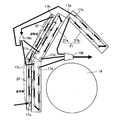
室内機2は、上面に室内空気の吸込口2aを有し、前面下部に空調用空気の吹出口2bとを有している。室内機2内には、吸込口2aから吹出口2bに向かって空気流路が形成され、この空気流路には、室内熱交換器14と、横流型の室内ファン16が配置される。したがって、室内ファン16が回転すると、室内空気が吸込口2aから室内ユニット1内に吸込まれる。室内機2の前側において、吸込口2aからの吸込み空気は、補助熱交換器20と主熱交換器21を通って室内ファン16側に流れる。一方、室内機2の背面側において、吸込口2aからの吸込み空気は、主熱交換器21を通って室内ファン16側に流れる。
室内熱交換器14は、上述したように、補助熱交換器20と、冷房運転モードおよび所定の除湿運転モードで運転されているときに、補助熱交換器20の下流側に配置された主熱交換器21を有している。主熱交換器21は、室内機2の前面側に配置された前面熱交換器21aと、室内機2の背面側に配置された背面熱交換器21bとを有しており、この熱交換器21a、21bが、室内ファン16を囲むように逆V字状に配置される。そして、補助熱交換器20が前面熱交換器21aの前方に配置される。補助熱交換器20および主熱交換器21(前面熱交換器21a、背面熱交換器21b)は、それぞれ、熱交換パイプおよび多数枚のフィンを備えている。
冷房運転モードおよび所定の除湿運転モードでは、図3に示すように、補助熱交換器20の下方の端部近くに配置された液入口17aから液冷媒が供給され、その供給された液冷媒は、補助熱交換器20の上端に近付くように流れる。そして、補助熱交換器20の上端近くに配置された出口17bから流れ出て分岐部18aに流れる。分岐部18aにおいて分岐された冷媒が、それぞれ、主熱交換器21の3つの入口17cから、前面熱交換器21aの下方部分と上方部分と背面熱交換器21bに供給され、その後、出口17dから流れ出て合流部18bで合流する。また、暖房運転モードでは、冷媒が上記と反対方向に流れる。
そして、空気調和機1では、所定の除湿運転モードでの運転が行われているとき、補助熱交換器20の液入口17aから供給された液冷媒は、補助熱交換器20の途中で全て蒸発する。したがって、補助熱交換器20の液入口17a近くの一部の範囲だけが、液冷媒が蒸発する蒸発域である。よって、所定の除湿運転モードで運転されているとき、室内熱交換器14において、補助熱交換器20の上流側の一部だけが蒸発域であって、補助熱交換器20の蒸発域の下流側の範囲と主熱交換器21とは、いずれも過熱域である。
そして、補助熱交換器20の上端近くの過熱域を流れた冷媒が、補助熱交換器20の下方部分の風下側に配置された前面熱交換器21aの下方部分を流れる。したがって、吸込口2aからの吸込空気において、補助熱交換器20の蒸発域で冷却された空気は、前面熱交換器21aで加熱された後で、吹出口2bから吹き出される。一方、吸込口2aからの吸込空気において、補助熱交換器20の過熱域と前面熱交換器21aを流れた空気と、背面熱交換器21bを流れた空気とは、室内温度と略同一の温度で、吹出口2bから吹き出される。
空気調和機1では、図1に示すように、室外機3に、冷媒回路において膨張弁13の下流側において蒸発温度を検知する蒸発温度センサ30が取り付けられる。そして、室内機2に、室内温度(室内機2の吸込口2aからの吸込空気の温度)を検知する室内温度センサ31と、補助熱交換器20において液冷媒の蒸発が終了したことを検知する室内熱交温度センサ32が取付けられる。
室内熱交温度センサ32は、図3に示すように、補助熱交換器20の上端近くの風下側に配置される。そして、補助熱交換器20の上端近くの過熱域では、吸込口2aからの吸込空気がほとんど冷却されない。したがって、室内熱交温度センサ32で検知される温度が、室内温度センサ31で検知される室内温度と略同一である場合には、補助熱交換器20の途中で蒸発が終了して、補助熱交換器20の上端近くの範囲が過熱域であることを検知できる。また、室内熱交温度センサ32は、室内熱交換器14の中間部の伝熱管に配置される。したがって、室内熱交換器14の中間部近くにおいて、冷暖房運転での凝縮温度または蒸発温度を検知できる。
図4に示すように、空気調和機1の制御部には、圧縮機10と、四方弁11、膨張弁13と、室内ファン16を駆動するモータ16aと、蒸発温度センサ30と、室内温度センサ31と、室内熱交温度センサ32とが接続される。したがって、制御部は、リモコンからの指令(運転開始操作や室内温度の設定温度等)や、蒸発温度センサ30で検知される蒸発温度、室内温度センサ31で検知される室内温度(吸込空気の温度)、室内熱交温度センサ32で検知される熱交中間温度に基づいて空気調和機1の運転を制御する。
そして、空気調和機1では、所定の除湿運転モードにおいて、補助熱交換器20が、液冷媒が蒸発する蒸発域と蒸発域の下流側の過熱域を有するが、この蒸発域の範囲が、負荷に応じて変化するように、圧縮機10及び膨張弁13が制御される。ここで、負荷に応じて変化するとは、蒸発域に供給される熱量に応じて変化することであって、熱量は例えば室内温度(吸込空気の温度)と室内風量によって決まる。また、負荷は、必要除湿能力(必要冷房能力)に対応しており、例えば室内温度と設定温度との差に基づいて検知できる。
圧縮機10は、室内温度と設定温度との差に基づいて制御される。室内温度と設定温度との差が大きい場合に負荷が大きいことから圧縮機10の周波数が増加され、室内温度と設定温度との差が小さい場合に負荷が小さいことから、圧縮機10の周波数が減少するように制御される。
膨張弁13は、蒸発温度センサ30で検知される蒸発温度に基づいて制御される。上述したように、圧縮機10の周波数が制御された状態において、蒸発温度が目標蒸発温度(12℃)近くの所定範囲(10℃-14℃)内の温度になるように、膨張弁13が制御される。この蒸発温度の所定範囲は、圧縮機10の周波数によらず一定に制御されるのが好ましい。ただし、周波数によって、わずかに変化するようにしても実質的に一定であれば問題ない。
このように、所定の除湿運転モードにおいて、負荷に応じて圧縮機10及び膨張弁13を制御することによって、補助熱交換器20の蒸発域の範囲を変化して、蒸発温度が所定範囲内の温度になるようにできる。
空気調和機1では、補助熱交換器20及び前面熱交換器21aが、12段の伝熱管をそれぞれ有している。そして、所定の除湿運転モードにおいて補助熱交換器20の蒸発域となる段数が、前面熱交換器21aの段数の半分以上である場合、補助熱交換器の蒸発域の範囲を十分に広くできるので負荷の変動に十分に対応できる。特に負荷が大きい場合に効果がある。
図5は、膨張弁13において開度を変化したときの流量変化を示している。膨張弁13は、入力される駆動パルスの数に応じて開度が連続的に変化する。そして、開度が減少するにつれて、膨張弁13を流れる冷媒の流量が減少する。膨張弁13では、開度t0のときに全閉状態であって、開度t0からt1の間では、開度が増加するにつれて流量が第1の傾きにしたがって増加し、開度t1からt2の間では、開度が増加するにつれて流量が第2の傾きにしたがって増加する。ここで、第1の傾きは、第2の傾きより大きい。
補助熱交換器20の蒸発域の範囲が変化するように行われる制御について、一例を説明する。例えば、所定の除湿運転モードにおいて、補助熱交換器20の蒸発域の範囲が所定面積であるときに負荷が大きくなった場合、圧縮機10の周波数が増加されると共に、膨張弁13の開度が大きく変更される。したがって、補助熱交換器20の蒸発域の範囲が所定面積より大きくなって、室内機2に吸い込まれた風量が一定であっても、実際に蒸発域を通過する風量が増加する。
一方、所定の除湿運転モードにおいて、補助熱交換器20の蒸発域の範囲が所定面積であるときに負荷が小さくなった場合、圧縮機10の周波数が減少されると共に、膨張弁13の開度が小さく変更される。したがって、補助熱交換器20の蒸発域の範囲が所定面積より小さくなって、室内機2に吸い込まれた風量が一定であっても、実際に蒸発域を通過する風量が減少する。
<本実施形態の空気調和機の特徴>
本実施形態の空気調和機1では、除湿運転時において、補助熱交換器20の出口で十分に過熱が付いている場合には、その過熱域を流れた空気は、ほとんど冷却されないため、風下側の伝熱管を冷やさないので、補助熱交換器20の風下側の冷媒回路の温度を検知することで、補助熱交換器20の出口で過熱が付いていることを検出できる。また、暖房運転時に過冷却が付いたり、冷房運転時の圧損で、温度を誤検知して、運転が不安定になることが無い。
本実施形態の空気調和機1では、除湿運転時において、補助熱交換器20の出口で十分に過熱が付いている場合には、その過熱域を流れた空気は、ほとんど冷却されないため、風下側の伝熱管を冷やさないので、補助熱交換器20の風下側の冷媒回路の温度を検知することで、補助熱交換器20の出口で過熱が付いていることを検出できる。また、暖房運転時に過冷却が付いたり、冷房運転時の圧損で、温度を誤検知して、運転が不安定になることが無い。
また、本実施形態の空気調和機1では、室内熱交温度センサ32が、室内熱交換器14の中間部の熱交換パイプに配置されるので、室内熱交換器14の中間部近くにおいて、冷暖房運転での凝縮温度または蒸発温度を検知できる。
さらに、本実施形態の空気調和機1では、補助熱交換器20における液入口17aが下方にあって、室内熱交温度センサ32が補助熱交換器20の上端近くに配置されるので、補助熱交換器20の蒸発域の範囲を大きくできる。
また、本実施形態の空気調和機1では、主熱交換器21が、室内機2内の前面側に配置された前面熱交換器21aと、室内機2内の背面側に配置された背面熱交換器21bとを有し、補助熱交換器20が、前面熱交換器21aの前方に配置されることで、補助熱交換器20の面積を大きくできるので、補助熱交換器20の蒸発域が変化する範囲を大きくできる。
以上、本発明の実施形態について図面に基づいて説明したが、具体的な構成は、これらの実施形態に限定されるものでないと考えられるべきである。本発明の範囲は、上記した実施形態の説明ではなく請求の範囲によって示され、さらに請求の範囲と均等の意味及び範囲内でのすべての変更が含まれる。
上述の実施形態において、補助熱交換器と主熱交換器とが一体に構成されてもよい。したがって、この場合、室内熱交換器が一体に構成され、室内熱交換器の最風上側に、補助熱交換器に対応した部分が設けられ、その風下側に、主熱交換器に対応した部分が設けられる。
また、上述の実施形態では、冷房運転モード、所定の除湿運転モードおよび暖房運転モードでの運転を行う空気調和機について説明したが、所定の除湿運転モードの他の方法で除湿運転を行う除湿運転モードでの運転を行う空気調和機であってもよい。
本発明を利用すれば、液冷媒の蒸発が終了したことを検知するセンサと、冷暖房運転での凝縮温度または蒸発温度を検知するためのセンサとを兼用できる。
1 空気調和機
2 室内機
3 室外機
10 圧縮機
12 室外熱交換器
13 膨張弁
14 室内熱交換器
16 室内ファン
20 補助熱交換器
21 主熱交換器
2 室内機
3 室外機
10 圧縮機
12 室外熱交換器
13 膨張弁
14 室内熱交換器
16 室内ファン
20 補助熱交換器
21 主熱交換器
Claims (4)
- 圧縮機と、室外熱交換器と、膨張弁と、室内熱交換器とを接続した冷媒回路を備え、
前記室内熱交換器が、除湿運転時に、最風上側に配置され且つ液冷媒が供給される補助熱交換器と、前記補助熱交換器の下流側に配置された主熱交換器とを有し、
除湿運転時において、前記補助熱交換器は液冷媒が蒸発する蒸発域と前記蒸発域の下流側の過熱域を有しており、
前記補助熱交換器において液冷媒の蒸発が終了していることを検知するための温度検知手段が、前記補助熱交換器の風下側に配置されることを特徴とする空気調和機。 - 前記温度検知手段が、前記室内熱交換器における冷媒経路の中央近くに配置されることを特徴とする請求項1に記載の空気調和機。
- 前記補助熱交換器における液入口が下方にあって、
前記温度検知手段が、前記補助熱交換器の上端近くに配置されることを特徴とする請求項1または2に記載の空気調和機。 - 前記主熱交換器が、室内機内の前面側に配置された前面熱交換器と、室内機内の背面側に配置された背面熱交換器とを有し、
前記補助熱交換器が、前記前面熱交換器の前方に配置されることを特徴とする請求項1-3のいずれかに記載の空気調和機。
Priority Applications (3)
| Application Number | Priority Date | Filing Date | Title |
|---|---|---|---|
| EP13777485.7A EP2857768B1 (en) | 2012-04-16 | 2013-04-04 | Air conditioner |
| ES13777485T ES2822249T3 (es) | 2012-04-16 | 2013-04-04 | Aparato de aire acondicionado |
| CN201380020149.XA CN104246387B (zh) | 2012-04-16 | 2013-04-04 | 空调机 |
Applications Claiming Priority (2)
| Application Number | Priority Date | Filing Date | Title |
|---|---|---|---|
| JP2012-093126 | 2012-04-16 | ||
| JP2012093126A JP5310904B1 (ja) | 2012-04-16 | 2012-04-16 | 空気調和機 |
Publications (1)
| Publication Number | Publication Date |
|---|---|
| WO2013157401A1 true WO2013157401A1 (ja) | 2013-10-24 |
Family
ID=49383365
Family Applications (1)
| Application Number | Title | Priority Date | Filing Date |
|---|---|---|---|
| PCT/JP2013/060348 WO2013157401A1 (ja) | 2012-04-16 | 2013-04-04 | 空気調和機 |
Country Status (5)
| Country | Link |
|---|---|
| EP (1) | EP2857768B1 (ja) |
| JP (1) | JP5310904B1 (ja) |
| CN (1) | CN104246387B (ja) |
| ES (1) | ES2822249T3 (ja) |
| WO (1) | WO2013157401A1 (ja) |
Cited By (1)
| Publication number | Priority date | Publication date | Assignee | Title |
|---|---|---|---|---|
| US10513626B2 (en) | 2013-06-26 | 2019-12-24 | 3M Innovative Properties Company | Stain resistant microsphere articles |
Families Citing this family (2)
| Publication number | Priority date | Publication date | Assignee | Title |
|---|---|---|---|---|
| CN113348328B (zh) * | 2019-02-05 | 2023-03-14 | 三菱电机株式会社 | 空调机 |
| JP6881641B2 (ja) * | 2019-03-25 | 2021-06-02 | ダイキン工業株式会社 | 空気調和機および空気調和システム |
Citations (4)
| Publication number | Priority date | Publication date | Assignee | Title |
|---|---|---|---|---|
| JPH0634184A (ja) * | 1992-07-21 | 1994-02-08 | Fujitsu General Ltd | 空気調和機 |
| JPH0914727A (ja) | 1995-06-28 | 1997-01-17 | Toshiba Corp | 空気調和機 |
| JPH0972599A (ja) * | 1995-06-28 | 1997-03-18 | Toshiba Ave Corp | 空気調和機 |
| JPH0996433A (ja) * | 1995-09-29 | 1997-04-08 | Toshiba Corp | 空気調和機 |
Family Cites Families (5)
| Publication number | Priority date | Publication date | Assignee | Title |
|---|---|---|---|---|
| US5678417A (en) * | 1995-06-28 | 1997-10-21 | Kabushiki Kaisha Toshiba | Air conditioning apparatus having dehumidifying operation function |
| JP4312894B2 (ja) * | 1999-09-09 | 2009-08-12 | 東芝キヤリア株式会社 | 空気調和機の室内ユニット |
| EP1092927B1 (en) * | 1999-10-14 | 2006-07-26 | Sharp Kabushiki Kaisha | Air conditioner and humidifying/dehumidifying apparatus attached thereto |
| JP2003232553A (ja) * | 2002-02-07 | 2003-08-22 | Daikin Ind Ltd | 空気調和機 |
| JP2010281548A (ja) * | 2009-06-08 | 2010-12-16 | Sharp Corp | 空気調和機 |
-
2012
- 2012-04-16 JP JP2012093126A patent/JP5310904B1/ja active Active
-
2013
- 2013-04-04 ES ES13777485T patent/ES2822249T3/es active Active
- 2013-04-04 WO PCT/JP2013/060348 patent/WO2013157401A1/ja unknown
- 2013-04-04 EP EP13777485.7A patent/EP2857768B1/en active Active
- 2013-04-04 CN CN201380020149.XA patent/CN104246387B/zh active Active
Patent Citations (4)
| Publication number | Priority date | Publication date | Assignee | Title |
|---|---|---|---|---|
| JPH0634184A (ja) * | 1992-07-21 | 1994-02-08 | Fujitsu General Ltd | 空気調和機 |
| JPH0914727A (ja) | 1995-06-28 | 1997-01-17 | Toshiba Corp | 空気調和機 |
| JPH0972599A (ja) * | 1995-06-28 | 1997-03-18 | Toshiba Ave Corp | 空気調和機 |
| JPH0996433A (ja) * | 1995-09-29 | 1997-04-08 | Toshiba Corp | 空気調和機 |
Non-Patent Citations (1)
| Title |
|---|
| See also references of EP2857768A4 |
Cited By (1)
| Publication number | Priority date | Publication date | Assignee | Title |
|---|---|---|---|---|
| US10513626B2 (en) | 2013-06-26 | 2019-12-24 | 3M Innovative Properties Company | Stain resistant microsphere articles |
Also Published As
| Publication number | Publication date |
|---|---|
| ES2822249T3 (es) | 2021-04-29 |
| CN104246387B (zh) | 2015-11-25 |
| CN104246387A (zh) | 2014-12-24 |
| EP2857768A4 (en) | 2016-04-06 |
| EP2857768A1 (en) | 2015-04-08 |
| EP2857768B1 (en) | 2020-08-26 |
| JP5310904B1 (ja) | 2013-10-09 |
| JP2013221672A (ja) | 2013-10-28 |
Similar Documents
| Publication | Publication Date | Title |
|---|---|---|
| JP5533926B2 (ja) | 空気調和機 | |
| JP6044238B2 (ja) | 空気調和機 | |
| JP5817803B2 (ja) | 空気調和機 | |
| JP5805579B2 (ja) | 空気調和機 | |
| JP5749210B2 (ja) | 空気調和機 | |
| JP5316668B1 (ja) | 空気調和機 | |
| JP6401015B2 (ja) | 空気調和機 | |
| JP5310904B1 (ja) | 空気調和機 | |
| JP5573881B2 (ja) | 空気調和機 | |
| JP5803898B2 (ja) | 空気調和機 | |
| JP6070624B2 (ja) | 空気調和機 | |
| JP2014159954A5 (ja) | ||
| JP5780199B2 (ja) | 空気調和機 | |
| KR102032178B1 (ko) | 공조 냉각 일체형 시스템 |
Legal Events
| Date | Code | Title | Description |
|---|---|---|---|
| 121 | Ep: the epo has been informed by wipo that ep was designated in this application |
Ref document number: 13777485 Country of ref document: EP Kind code of ref document: A1 |
|
| NENP | Non-entry into the national phase |
Ref country code: DE |