WO2013154185A1 - 高温超電導機器の冷却装置及びその運転方法 - Google Patents
高温超電導機器の冷却装置及びその運転方法 Download PDFInfo
- Publication number
- WO2013154185A1 WO2013154185A1 PCT/JP2013/061066 JP2013061066W WO2013154185A1 WO 2013154185 A1 WO2013154185 A1 WO 2013154185A1 JP 2013061066 W JP2013061066 W JP 2013061066W WO 2013154185 A1 WO2013154185 A1 WO 2013154185A1
- Authority
- WO
- WIPO (PCT)
- Prior art keywords
- temperature
- heat exchanger
- refrigerant gas
- gas
- coolant
- Prior art date
- Legal status (The legal status is an assumption and is not a legal conclusion. Google has not performed a legal analysis and makes no representation as to the accuracy of the status listed.)
- Ceased
Links
Images

Classifications
-
- F—MECHANICAL ENGINEERING; LIGHTING; HEATING; WEAPONS; BLASTING
- F25—REFRIGERATION OR COOLING; COMBINED HEATING AND REFRIGERATION SYSTEMS; HEAT PUMP SYSTEMS; MANUFACTURE OR STORAGE OF ICE; LIQUEFACTION SOLIDIFICATION OF GASES
- F25B—REFRIGERATION MACHINES, PLANTS OR SYSTEMS; COMBINED HEATING AND REFRIGERATION SYSTEMS; HEAT PUMP SYSTEMS
- F25B5/00—Compression machines, plants or systems, with several evaporator circuits, e.g. for varying refrigerating capacity
- F25B5/04—Compression machines, plants or systems, with several evaporator circuits, e.g. for varying refrigerating capacity arranged in series
-
- F—MECHANICAL ENGINEERING; LIGHTING; HEATING; WEAPONS; BLASTING
- F25—REFRIGERATION OR COOLING; COMBINED HEATING AND REFRIGERATION SYSTEMS; HEAT PUMP SYSTEMS; MANUFACTURE OR STORAGE OF ICE; LIQUEFACTION SOLIDIFICATION OF GASES
- F25B—REFRIGERATION MACHINES, PLANTS OR SYSTEMS; COMBINED HEATING AND REFRIGERATION SYSTEMS; HEAT PUMP SYSTEMS
- F25B25/00—Machines, plants or systems, using a combination of modes of operation covered by two or more of the groups F25B1/00 - F25B23/00
- F25B25/005—Machines, plants or systems, using a combination of modes of operation covered by two or more of the groups F25B1/00 - F25B23/00 using primary and secondary systems
-
- F—MECHANICAL ENGINEERING; LIGHTING; HEATING; WEAPONS; BLASTING
- F25—REFRIGERATION OR COOLING; COMBINED HEATING AND REFRIGERATION SYSTEMS; HEAT PUMP SYSTEMS; MANUFACTURE OR STORAGE OF ICE; LIQUEFACTION SOLIDIFICATION OF GASES
- F25B—REFRIGERATION MACHINES, PLANTS OR SYSTEMS; COMBINED HEATING AND REFRIGERATION SYSTEMS; HEAT PUMP SYSTEMS
- F25B40/00—Subcoolers, desuperheaters or superheaters
-
- F—MECHANICAL ENGINEERING; LIGHTING; HEATING; WEAPONS; BLASTING
- F25—REFRIGERATION OR COOLING; COMBINED HEATING AND REFRIGERATION SYSTEMS; HEAT PUMP SYSTEMS; MANUFACTURE OR STORAGE OF ICE; LIQUEFACTION SOLIDIFICATION OF GASES
- F25B—REFRIGERATION MACHINES, PLANTS OR SYSTEMS; COMBINED HEATING AND REFRIGERATION SYSTEMS; HEAT PUMP SYSTEMS
- F25B41/00—Fluid-circulation arrangements
-
- F—MECHANICAL ENGINEERING; LIGHTING; HEATING; WEAPONS; BLASTING
- F25—REFRIGERATION OR COOLING; COMBINED HEATING AND REFRIGERATION SYSTEMS; HEAT PUMP SYSTEMS; MANUFACTURE OR STORAGE OF ICE; LIQUEFACTION SOLIDIFICATION OF GASES
- F25B—REFRIGERATION MACHINES, PLANTS OR SYSTEMS; COMBINED HEATING AND REFRIGERATION SYSTEMS; HEAT PUMP SYSTEMS
- F25B49/00—Arrangement or mounting of control or safety devices
-
- F—MECHANICAL ENGINEERING; LIGHTING; HEATING; WEAPONS; BLASTING
- F25—REFRIGERATION OR COOLING; COMBINED HEATING AND REFRIGERATION SYSTEMS; HEAT PUMP SYSTEMS; MANUFACTURE OR STORAGE OF ICE; LIQUEFACTION SOLIDIFICATION OF GASES
- F25B—REFRIGERATION MACHINES, PLANTS OR SYSTEMS; COMBINED HEATING AND REFRIGERATION SYSTEMS; HEAT PUMP SYSTEMS
- F25B9/00—Compression machines, plants or systems, in which the refrigerant is air or other gas of low boiling point
- F25B9/06—Compression machines, plants or systems, in which the refrigerant is air or other gas of low boiling point using expanders
-
- F—MECHANICAL ENGINEERING; LIGHTING; HEATING; WEAPONS; BLASTING
- F25—REFRIGERATION OR COOLING; COMBINED HEATING AND REFRIGERATION SYSTEMS; HEAT PUMP SYSTEMS; MANUFACTURE OR STORAGE OF ICE; LIQUEFACTION SOLIDIFICATION OF GASES
- F25B—REFRIGERATION MACHINES, PLANTS OR SYSTEMS; COMBINED HEATING AND REFRIGERATION SYSTEMS; HEAT PUMP SYSTEMS
- F25B2700/00—Sensing or detecting of parameters; Sensors therefor
- F25B2700/21—Temperatures
- F25B2700/2117—Temperatures of an evaporator
- F25B2700/21171—Temperatures of an evaporator of the fluid cooled by the evaporator
Definitions
- the present invention relates to a cooling apparatus for high-temperature superconducting equipment and an operation method thereof.
- This application claims priority based on Japanese Patent Application No. 2012-092079 filed in Japan on April 13, 2012, the contents of which are incorporated herein by reference.
- HTS devices such as transformers, power transmission cables, and motors using high temperature superconducting (hereinafter referred to as “HTS”) need to be cooled to about 60 to 80K in order to maintain the superconducting state.
- a cooling system refrigerator
- a refrigerator having a refrigerating capacity of about 2 to 10 kW is required.
- the HTS device is cooled by, for example, liquid nitrogen, and this liquid nitrogen is circulated by the liquid nitrogen circulation device in a subcooled state.
- the liquid nitrogen in the liquid nitrogen circulation device is cooled by a refrigerator.
- the subcooled state refers to a state in which the liquid temperature is lower than its saturation temperature.
- liquid nitrogen having a temperature from the boiling point (about 77 K) to the freezing point (about 63 K).
- the saturation temperature refers to a temperature at which the pressure of a certain liquid becomes equal to the saturation vapor pressure.
- a refrigerator required for HTS equipment not only its size but also cooling performance such as cooling temperature, refrigeration capacity, and refrigeration efficiency are important.
- the GM refrigerator or Stirling refrigerator cannot be used with the refrigeration capacity (60 to 80K, 0.1 to 0.6kW).
- Brayton cycle refrigerator Brayton Cycle Refrigerator
- a Brayton cycle refrigerator using neon gas as a refrigerant gas (working fluid, working fluid) and liquid nitrogen as a cooling liquid has been developed.
- the liquid nitrogen is cooled to the subcooled state by exchanging heat between the neon gas circulating in the Brayton cycle refrigerator and the liquid nitrogen circulating in the liquid nitrogen circulation device in the auxiliary heat exchanger.
- a plate fin heat exchanger can be downsized.
- a heating means for example, a heater or the like
- the liquid nitrogen channel is not frozen, so that the liquid nitrogen temperature is higher than the freezing point. It can also be controlled.
- a problem that requires extra equipment such as a heater occurs. In the first place, the need for extra equipment such as a heater means that liquid nitrogen is cooled too much, that is, the Brayton cycle refrigerator cannot be operated efficiently.
- the present invention has been made to solve such a problem, and can be brought into a subcooling state without solidifying the cooling liquid, and even when the operating state of the object to be cooled changes suddenly. It is an object of the present invention to provide a cooling apparatus for a high-temperature superconducting device capable of maintaining a coolant at an appropriate temperature and an operation method thereof.
- a first aspect of the present invention includes a turbo compressor that compresses and circulates refrigerant gas; A main heat exchanger that cools the compressed refrigerant gas by heat exchange with the returned refrigerant gas (refrigerant gas before compression); An expansion turbine for adiabatically expanding the cooled refrigerant gas; A sub heat exchanger for exchanging heat between the cryogenic refrigerant gas exiting the expansion turbine and the coolant; A circulation pump for circulating the cooling liquid between the auxiliary heat exchanger and a body to be cooled; Temperature measuring means for measuring the temperature of the coolant; A first closed flow path constituting a circulation path for circulating the refrigerant gas after heat exchange in the auxiliary heat exchanger to the turbo compressor via the main heat exchanger; A second closed flow path that constitutes a circulation path for circulating the coolant after the heat exchange with the auxiliary heat exchanger with the circulation pump; The auxiliary heat exchanger is A first heat exchanging unit having a path through which the refrigerant gas flows in parallel, and
- the temperature measuring unit measures the temperature of the coolant after heat exchange is performed by the auxiliary heat exchanger.
- the refrigerant gas is neon gas, a mixed gas of helium gas and neon gas, a mixed gas of hydrogen and neon gas, a mixed gas of hydrogen and helium gas, or neon gas, helium gas or the above-mentioned It is preferably one of mixed gases obtained by mixing an inert gas with a mixed gas.
- the cooling liquid is liquid nitrogen.
- the second aspect of the present invention is a method of operating the cooling device for the high-temperature superconducting equipment according to the first aspect of the present invention, Provided is a method of operating a cooling device for a high-temperature superconducting device, in which the temperature of refrigerant gas is controlled by the number of revolutions of a turbo compressor so that the coolant in the second closed flow path is in a temperature range in which the coolant is in a subcooled state.
- the circulating flow rate of the cooling liquid is controlled by the number of rotations of the circulating pump so that the cooling liquid in the second closed flow path is in a temperature range where the cooling liquid enters a subcooled state.
- the rotation speed of the circulation pump is preferably controlled by inverter control.
- a sub heat exchanger is provided in the cooling apparatus for bringing the coolant in the second closed flow path into a subcooled state, and the second heat exchanger in the sub heat exchanger is provided. Since the refrigerant gas in the first closed flow path is heat-exchanged by itself in the first heat exchange section and the coolant in the second closed flow path is cooled in the second heat exchange section, the sub heat exchanger The cooling liquid is not solidified inside.
- the turbo compressor provided in the first closed flow path only in accordance with the temperature change of the coolant on the outlet side of the auxiliary heat exchanger Since the number of rotations is controlled, the object to be cooled can be appropriately and efficiently cooled without solidifying the coolant in the sub heat exchanger even when there is a sudden change in the operating state of the object to be cooled. .
- the combination of the refrigerator 1 and the body 6 to be cooled according to the present embodiment is a first circulation in which a turbo compressor 2, a main heat exchanger 3, an expansion turbine 4, and a sub heat exchanger 5 are provided.
- a path (first closed flow path) L1 a second circulation path (second closed flow path) L2 provided with the auxiliary heat exchanger 5, the cooled object 6, the circulation pump 7, and the temperature measuring means 10, and
- the refrigerant gas circulating in the first circulation path L1 and the coolant circulating in the second circulation path L2 exchange heat with the auxiliary heat exchanger 5.
- the refrigerator 1 includes a turbo compressor 2, a main heat exchanger 3, an expansion turbine 4, an auxiliary heat exchanger 5, a temperature measuring means 10, and a circulation pump 7. It is only the to-be-cooled body 6 provided outside 1. Moreover, all the components of the refrigerator 1 other than the cooled object 6 are accommodated in the same vacuum container (cold box).
- the refrigerator 1 of the present embodiment adiabatically compresses a refrigerant gas such as neon gas with a turbo compressor 2, and the main heat exchanger 3 returns a high-pressure side refrigerant gas and a low-pressure side return gas.
- the refrigerant gas on the high pressure side is cooled by heat exchange with the refrigerant gas, and the cooled refrigerant gas adiabatically expands in the expansion turbine 4, so that the refrigerant gas itself becomes a very low temperature, and the auxiliary heat exchanger 5
- the coolant is cooled by exchanging heat between the low-temperature refrigerant gas and the coolant such as liquid nitrogen sent from the circulation pump 7, and the cooled object 6 such as an HTS device is cooled with this coolant. .
- the refrigerant gas helium, neon or hydrogen having a lower boiling point than nitrogen and a mixed gas thereof, or a mixed gas in which an inert gas such as nitrogen or argon is slightly mixed with these gases can be used.
- the coolant is not particularly limited, but for example, liquid nitrogen can be used.
- the first circulation path L1 includes a turbo compressor 2 that compresses and circulates the refrigerant gas, a main heat exchanger 3 that cools the adiabatic-compressed refrigerant gas by heat exchange with the returned refrigerant gas, and the cooled refrigerant gas.
- a circulation path that circulates to the turbo compressor 2 through an expansion turbine 4 that adiabatically expands and an auxiliary heat exchanger that exchanges heat between the cryogenic refrigerant gas derived from the expansion turbine 4 and the coolant.
- the turbo compressor 2 is provided in the first circulation path L1 for adiabatically compressing and circulating the refrigerant gas.
- a single-stage turbo compressor is illustrated, but the present invention is not limited to this.
- a two-stage turbo compressor including an intercooler or the like may be used.
- the turbo compressor 2 may be driven by an inverter.
- the turbo compressor When the turbo compressor is driven by an inverter, when the outlet side pressure of the turbo compressor 2 becomes higher than a predetermined value, the output frequency of the inverter is changed to reduce the rotational speed of the turbo compressor 2. be able to. Therefore, the outlet side pressure of the turbo compressor 2 can be kept below a predetermined value.
- the turbo compressor 2 can perform inverter control, the number of revolutions can be suitably controlled.
- the rotation speed of the turbo compressor 2 is increased by changing the output frequency of the inverter, the outlet side pressure of the turbo compressor 2 can be increased.
- a heat exchanger may be provided at the rear stage on the outlet side of the turbo compressor 2. With this heat exchanger, the high-temperature refrigerant gas emitted from the turbo compressor 2 can be cooled to near atmospheric temperature.
- An example is a water-cooled aftercooler.
- the main heat exchanger 3 is installed between the turbo compressor 2 and the expansion turbine 4 in the first circulation path L1, and the refrigerant gas adiabatically compressed by the turbo compressor 2 and The refrigerant gas discharged from the turbo compressor 2 is cooled by exchanging heat with the refrigerant gas returned from the auxiliary heat exchanger 5.
- the expansion turbine 4 is installed at the rear stage of the main heat exchanger 3 in the first circulation path L1, and a refrigerant gas cooled by the main heat exchanger 3 is adiabatically expanded to generate a cryogenic temperature.
- Refrigerant gas may be integrated with the turbo compressor 2 so as to be provided coaxially. Since the power for operating the expansion turbine 4 and the turbo compressor 2 can be integrated by adopting an integral structure, the refrigerator can be miniaturized.
- the outlet temperature of the expansion turbine 4 (corresponding to the temperature at point 1 in FIG. 2) depends on the type of refrigerant gas, but in the cooling device of the present invention in which a main heat exchanger and a sub heat exchanger are combined, Often within the range of 55K to 65K.
- the auxiliary heat exchanger 5 is installed on the outlet side of the expansion turbine 4 in the first circulation path L ⁇ b> 1, and cools the refrigerant gas and the object 6 to be cooled that have been extremely cooled by the expansion turbine 4.
- the cooling liquid is cooled by exchanging heat with the cooling liquid. That is, the object to be cooled is cooled by the coolant gas cooling the coolant.
- the circulation pump 7 circulates the coolant in the second circulation path L2.
- the second circulation path L ⁇ b> 2 is provided with a temperature measuring means 10 for measuring the temperature of the coolant flowing out from the sub heat exchanger 5.
- the temperature measuring means 10 include a thermocouple.
- HTS apparatus such as a superconducting power transmission cable, a superconducting transformer, a superconducting motor, is mentioned, for example.
- the refrigerant gas is adiabatically compressed by the turbo compressor 2 in the first circulation path L1.
- the refrigerant gas is introduced into the main heat exchanger 3 and heat exchanged with the refrigerant gas returned from the auxiliary heat exchanger 5 (the refrigerant gas before being adiabatically compressed).
- the adiabatic-compressed refrigerant gas is cooled to 65 to 70K. Since the refrigerant gas adiabatically compressed by the turbo compressor 2 becomes a high temperature, a heat exchanger may be provided at the subsequent stage of the turbo compressor 2 to cool the refrigerant gas to near the atmospheric temperature.
- the expansion turbine 4 adiabatic expansion from the pressure (high pressure side pressure, 1 to 2 MPa) for introducing the refrigerant gas to the expansion turbine 4 to the pressure (low pressure side pressure, 0.5 to 1 MPa) derived from the expansion turbine 4 is performed.
- the refrigerant gas temperature is lowered to 55 to 65K.
- the refrigerant gas cooled to 55 to 65 K by the expansion turbine 4 is introduced into the auxiliary heat exchanger 5 and heat exchanged with the cooling liquid for cooling the cooled object 6.
- the coolant is cooled to the subcooled state. For example, when liquid nitrogen is cooled to 65K, the refrigerant gas temperature rises to about 65 to 70K.
- the coolant in the subcooled state circulates through the second circulation path L2 so that the cooled body 6 is maintained at a constant temperature by the circulation pump 7.
- the temperature range of the coolant in the subcooled state is a temperature from the boiling point (about 77 K) to the freezing point (about 63 K).
- the temperature of the coolant for cooling the cooled object 6 is constantly monitored by the temperature measuring means 10. Although the temperature at which the object to be cooled 6 is held varies slightly depending on the HTS equipment, most of them are cooled and maintained at about 70K.
- the refrigerant gas (returned refrigerant gas) derived from the auxiliary heat exchanger 5 returns to the main heat exchanger 3 and is heat-exchanged with the refrigerant gas adiabatically compressed by the turbo compressor 2. At this time, the temperature of the refrigerant gas (returned refrigerant gas) derived from the auxiliary heat exchanger 5 further increases to near the atmospheric temperature. Thereafter, the refrigerant gas (returned refrigerant gas) derived from the auxiliary heat exchanger 5 returns to the inlet side of the turbo compressor.
- the first circulation path L1 provided in the refrigerator 1 of the present embodiment is configured such that the refrigerant gas circulates, and constitutes a Brayton cycle. Further, when the pressure loss of the cooling gas is large in the auxiliary heat exchanger 5, the expansion turbine 4 is provided in the rear stage of the auxiliary heat exchanger 5, that is, in the front stage of the main heat exchanger 3, in the first circulation path L1. A high-pressure refrigerant gas of 2 MPa can be introduced into the auxiliary heat exchanger 5. Thereby, even if the pressure loss of the cooling gas is large in the auxiliary heat exchanger 5, it can be dealt with.
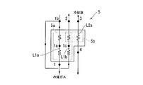
- the sub heat exchanger 5 of the present embodiment will be described in more detail based on FIG.
- the first circulation path L1 through which the refrigerant gas flows is arranged so that the path L1a and the path L1b are in parallel (the refrigerant gas in the path L1a and the path L1b
- the first heat exchange section 5a is formed so that the refrigerant gas is in a parallel flow.
- the second heat exchange is performed so that the path L2a through which the coolant flows is opposed to the path L1b through which the refrigerant gas flows (so that the path L1b and the path L2a are opposed to each other). Part 5b is formed.
- the temperature of the refrigerant gas cooled by the expansion turbine 4 is exchanged between the refrigerant gases in the parallel flow portion of the first heat exchange section 5a.
- heat is exchanged between the refrigerant gas and the cooling liquid (subcooled state) for cooling the cooled object 6 to cool the cooling liquid.
- the refrigerant gas and the cooling liquid are heat-exchanged in a state where the cooling liquid is in the subcooled state and the freezing point or higher.
- the temperature of the coolant changes due to the load fluctuation / operation change of the cooled object (HTS device) 6.
- the temperature measuring means 10 is provided in the subsequent stage of the auxiliary heat exchanger 5 (that is, the preceding stage of the cooled object 6), so that the cooled object 6 is cooled.
- the temperature of the coolant to be measured can always be measured.
- the rotational speed of the turbo compressor 2 can be controlled in accordance with the measured temperature of the coolant. When the measured temperature of the coolant is lowered, that is, when the load on the cooled object 6 such as an HTS device is reduced, the rotational speed of the turbo compressor 2 is lowered.
- the rotational speed of the turbo compressor 2 is increased.
- the refrigeration capacity of the refrigerator 1 can be changed by controlling the rotational speed of the turbo compressor 2.
- the expansion ratio of the expansion turbine 4 is determined by the relationship between the high pressure side pressure and the low pressure side pressure of the refrigerator 1. It is the compression ratio of the turbo compressor 2 that determines these pressures in the refrigerator 1.
- the expansion turbine 4 only has a function of expanding the refrigerant gas outlet pressure (high pressure side pressure) increased through the turbo compressor 2 to the refrigerant gas inlet pressure (low pressure side pressure) of the turbo compressor 2.
- the expansion ratio cannot be determined by the expansion turbine 4 itself. That is, the expansion ratio of the refrigerant gas in the expansion turbine 4 is determined according to the compression ratio of the refrigerant gas in the turbo compressor 2.
- the refrigerant gas can be quickly controlled by controlling the rotation speed of the turbo compressor 2 in accordance with the load fluctuation / operation change of the cooled object 6 such as an HTS device. Can be maintained at an appropriate temperature. Therefore, the to-be-cooled body 6 can be kept at a constant temperature.
- the refrigerator 1 of the present embodiment is a sub heat exchanger for bringing the coolant (liquid nitrogen) in the second circulation path L2 into a subcool state in the refrigerator 1 constituting the Brayton cycle.
- the refrigerant gas (neon gas) in the first circulation path L1 is heat-exchanged by the first heat exchange section 5a in the sub heat exchanger 5 and the second circulation path L2 in the second heat exchange section 5b. It is comprised so that the inside coolant may be cooled. Therefore, the cooling liquid is not solidified in the auxiliary heat exchanger 5.
- the rotation of the turbo compressor 2 provided in the first circulation path L1 according to only the temperature change of the coolant on the outlet side of the auxiliary heat exchanger 5. Because the number is controlled, the high-temperature superconductor in the HTS device is not solidified in the sub heat exchanger 5 even if there is a sudden change in the operating state of the cooled object (HTS device) 6. It can be cooled appropriately and efficiently.
- the rotational speed of the turbo compressor 2 is controlled so that the temperature 10 at the coolant outlet (point 4) of the auxiliary heat exchanger 5 is constant. Therefore, if the circulating flow rate of the coolant is constant, the temperature of the coolant inlet (point 3) of the auxiliary heat exchanger 5 depends on the load of the body 6 to be cooled. When the load on the cooled object 6 decreases, the temperature of the coolant inlet (point 3) of the auxiliary heat exchanger 5 decreases, and the temperature of the refrigerant gas that returns to the main heat exchanger 3 also decreases. Furthermore, the inlet temperature of the expansion turbine 4 also decreases.
- the refrigerant gas whose temperature has decreased in the sub heat exchanger 5 and the cooling gas whose temperature has increased perform heat exchange, so that the cooling liquid in the sub heat exchanger 5 can be prevented from solidifying.
- the circulating flow rate of the coolant is restored by immediately increasing the rotational speed of the turbo compressor 2 and the rotational speed of the circulation pump 7 to the original values.
- Example 1 The refrigerator to which the cooling device for the high-temperature superconducting equipment of the present invention shown in FIG. 1 was applied was operated until it reached a steady state. Neon gas was used as the refrigerant gas, and liquid nitrogen was used as the coolant. The results of measuring the temperature at each point (measurement point) shown in FIG.
- the temperature at point 1a shown in FIG. 2 was 64.8K
- the temperature at point 1c was 65.4K
- the temperature at point 4 was 67.0K
- the nitrogen temperature in the subcooled state under atmospheric pressure is from the boiling point (about 77 K) to the freezing point (about 63 K). Therefore, according to the refrigerator of the present invention, the refrigerant gas temperature can be maintained at a temperature at which the coolant does not solidify without using a heater or the like for heating the coolant.
- Example 2 The Brayton cycle refrigerator to which the cooling apparatus for high-temperature superconducting equipment of the present invention shown in FIG. Neon gas was used as the refrigerant gas, and liquid nitrogen was used as the coolant.
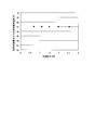
- the load of the HTS equipment fluctuates from 0.7 to 2.5 kW as shown in FIG. Even in this case, the temperature of the liquid nitrogen outlet (point 4) of the auxiliary heat exchanger was constant at 67K.
- the refrigerant gas temperature is maintained at a temperature at which the cooling liquid does not solidify without using a heater or the like for heating the cooling liquid even in the case of load fluctuation operation.
Landscapes
- Engineering & Computer Science (AREA)
- Physics & Mathematics (AREA)
- Mechanical Engineering (AREA)
- Thermal Sciences (AREA)
- General Engineering & Computer Science (AREA)
- Containers, Films, And Cooling For Superconductive Devices (AREA)
Abstract
Description
本願は、2012年4月13日に、日本に出願された特願2012-092079号に基づき優先権を主張し、その内容をここに援用する。
例えば、特許文献1にあるように、冷媒ガス(動作流体、作動流体)としてネオンガスを用い、冷却液として液体窒素を用いたブレイトンサイクル冷凍機が開発されている。ブレイトンサイクル冷凍機内を循環するネオンガスと、液体窒素循環装置内を循環する液体窒素と、が副熱交換器で熱交換することで、液体窒素をサブクール状態まで冷却している。
本発明の第1の態様は、冷媒ガスを圧縮・循環させるターボ圧縮機と、
圧縮した冷媒ガスを戻りの冷媒ガス(圧縮する前の冷媒ガス)との熱交換により冷却する主熱交換器と、
冷却した冷媒ガスを断熱膨張させる膨張タービンと、
前記膨張タービンを出た極低温の冷媒ガスと冷却液とを熱交換させる副熱交換器と、
前記冷却液を前記副熱交換器と被冷却体の間で循環させる循環ポンプと、
前記冷却液の温度を測定する温度測定手段と、
前記副熱交換器で熱交換した後の冷媒ガスを、前記主熱交換器を介して前記ターボ圧縮機に循環させる循環経路を構成する第1の閉流路と、
前記副熱交換器で熱交換した後の冷却液を、前記循環ポンプで循環させる循環経路を構成する第2の閉流路と、を備え、
前記副熱交換器は、
前記冷媒ガスが並行に流れる経路を有し、前記冷媒ガスが相互に熱交換する第1熱交換部と、
前記第1熱交換部で熱交換された冷媒ガスと前記冷却液とが対向するように熱交換する第2熱交換部と、を有する高温超電導機器の冷却装置を提供する。
第2の閉流路内の冷却液がサブクール状態となる温度範囲になるように、冷媒ガスの温度をターボ圧縮機の回転数により制御する高温超電導機器の冷却装置の運転方法を提供する。
また、本発明の第2の態様においては、第2の閉流路内の冷却液がサブクール状態となる温度範囲になるように、前記冷却液の循環流量を前記循環ポンプの回転数により制御し、前記循環ポンプの回転数をインバータ制御によって制御することが好ましい。
図1に示すように、本実施形態の冷凍機1と被冷却体6の組合せは、ターボ圧縮機2、主熱交換器3、膨張タービン4、副熱交換器5が設けられた第1循環経路(第1の閉流路)L1と、副熱交換器5、被冷却体6、循環ポンプ7、温度測定手段10が設けられた第2循環経路(第2の閉流路)L2と、を備えて概略構成されており、第1循環経路L1内を循環する冷媒ガスと第2循環経路L2を循環する冷却液とが副熱交換器5で熱交換するようになっている。
また、冷却液としては、特に限定されないが、例えば液体窒素を用いることができる。
なお、膨張タービン4の出口温度(図2における点1の温度に相当)は、冷媒ガスの種類に依存するが、主熱交換器と副熱交換器を組み合せた本願発明の冷却装置においては、55K~65Kの範囲内であることが多い。
また、図1に示すように、第2循環経路L2には、副熱交換器5から流出する冷却液の温度を測定するための温度測定手段10が設けられている。温度測定手段10としては、例えば、熱電対などがあげられる。
また、被冷却体6としては、例えば、超電導送電ケーブル、超電導変圧器、超電導モーター等のHTS機器が挙げられる。
まず、第1循環経路L1において、ターボ圧縮機2によって冷媒ガスが断熱圧縮される。次に、冷媒ガスは主熱交換器3に導入され、副熱交換器5からの戻りの冷媒ガス(断熱圧縮される前の冷媒ガス)と熱交換される。このとき、断熱圧縮された冷媒ガスは65~70Kまで冷却される。
なお、ターボ圧縮機2で断熱圧縮された冷媒ガスは高温となるため、ターボ圧縮機2の後段に熱交換器を設けて、冷媒ガスを大気温度近くまで冷却してもよい。
また、副熱交換器5で冷却ガスの圧力損失が大きい場合には、第1循環経路L1において、膨張タービン4を副熱交換器5の後段すなわち主熱交換器3の前段に設け、1~2MPaの高圧の冷媒ガスを副熱交換器5に導入することもできる。これにより、副熱交換器5で冷却ガスの圧力損失が大きい場合であっても対応することができる。
図2に示すように、副熱交換器5内には、冷媒ガスが流れる第1循環経路L1が、経路L1aと経路L1bとが並行するように(経路L1a内の冷媒ガスと経路L1b内の冷媒ガスが並行流となるように)、第1熱交換部5aが形成されている。また、副熱交換器5内には、冷却液が流れる経路L2aが、冷媒ガスが流れる経路L1bと対向するように(経路L1bと経路L2aとが対向流となるように)、第2熱交換部5bが形成されている。
すなわち、副熱交換器5では、冷却液がサブクール状態かつ凝固点以上の状態で、冷媒ガスと冷却液とが熱交換される。
以上により、冷凍機1の冷凍能力は、ターボ圧縮機2の回転数の制御によって変化させることがきる。
逆に、ターボ圧縮機2の回転数を上げると、ターボ圧縮機2の特性により圧縮比が大きくなり、結果、膨張タービン4の膨張比が大きくなるので、膨張タービン4から導出される冷媒ガス温度は回転数を上げる前よりも下降する。
本発明の高温超電導機器の冷却装置では、副熱交換器5の冷却液出口(点4)の温度10を一定とする様にターボ圧縮機2の回転数を制御している。よって、冷却液の循環流量が一定であれば、副熱交換器5の冷却液入口(点3)の温度は被冷却体6の負荷に依存する。
被冷却体6の負荷が減少すると、副熱交換器5の冷却液入口(点3)の温度が下降し、主熱交換器3に戻る冷媒ガスの温度も下降する。更に、膨張タービン4の入口温度も下降する。一方、被冷却体6の負荷が減少すると、冷凍能力を下げるためにターボ圧縮機2の回転数を下げる自動制御が行われる。ターボ圧縮機2の回転数が減少すると、冷媒ガスの圧縮比が流量とともに減少する。この時、膨張タービン4の入口温度の低下と膨張比の低下が同時に起こる。ただし、膨張タービンの出口温度は、用いたターボ圧縮機2と膨張タービン4の特性により上昇する場合と下降する場合がある。
膨張タービン4の出口温度が上昇した場合は、副熱交換器5の冷媒ガス入口(点1)の温度が上昇するので、副熱交換器5内で液体窒素(冷却液)が凝固することはない。一方、膨張タービン4の出口温度が下降した場合は、副熱交換器5の冷媒ガス入口(点1)の温度が下がるので、副熱交換器5内で冷却液が凝固する危険性がある。この冷却液の凝固を回避するため、副熱交換器5の冷媒ガス入口(点1)の温度に基づいて、循環ポンプ7の回転数を減少させ、冷却液の循環流量を減らすことが好ましい。冷却液の循環流量が減少すると、被冷却体6の影響によって冷却液の温度が上昇する。その結果、副熱交換器5において温度が下降した冷媒ガスと温度が上昇した冷却ガスが熱交換を行うことになるので、副熱交換器5内の冷却液の凝固を防ぐことができる。
被冷却体6の負荷が上昇し、定常に戻った場合には、直ちにターボ圧縮機2の回転数及び循環ポンプ7の回転数を元の数値まで増加させることで、冷却液の循環流量を回復させる。これにより、第2の閉流路L2内の冷却液の温度がサブクール状態となる温度範囲になるよう維持し、系全体の温度を安定に維持することができる。循環ポンプ7の回転数制御には、一般的なインバータ制御が適用可能である。
図1に示す本発明の高温超電導機器の冷却装置を適用した冷凍機を定常状態となるまで運転した。冷媒ガスにはネオンガスを用い、冷却液には液体窒素を用いた。図2中に示した各点(測定点)における温度を測定した結果を、以下の表1に示す。
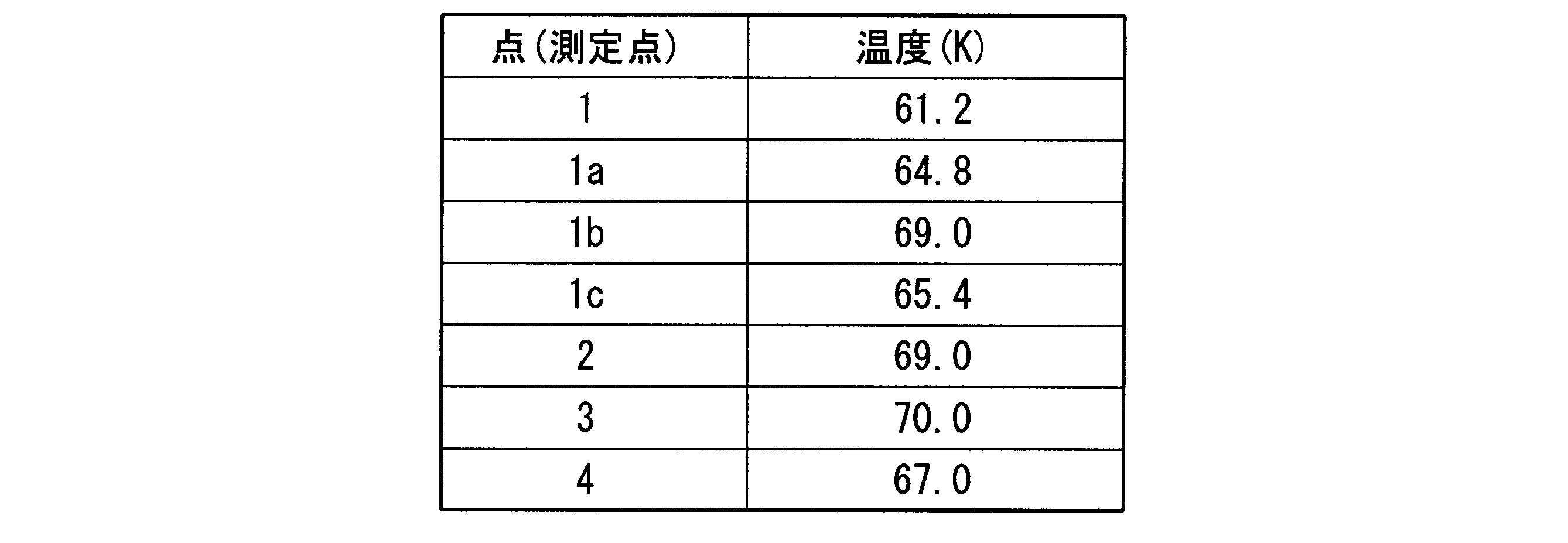
図1に示す本発明の高温超電導機器の冷却装置を適用したブレイトンサイクル冷凍機を負荷変動運転した。冷媒ガスにはネオンガスを用い、冷却液には液体窒素を用いた。
HTS機器の負荷を変動させて、ターボ圧縮機の回転数を制御し、冷凍機の冷凍能力を制御した結果、図3に示すように、HTS機器の負荷が0.7から2.5kWに変動した場合でも、副熱交換器の液体窒素出口(点4)の温度は67Kで一定であった。したがって、本発明の高温超電導機器の冷却装置によれば、負荷変動運転した場合であっても冷却液を加熱するためのヒーター等を用いることなく、冷媒ガス温度を冷却液が凝固しない温度に維持することができた。
2 ターボ圧縮機
3 主熱交換器
4 膨張タービン
5 副熱交換器
5a 第1熱交換部
5b 第2熱交換部
6 被冷却体
7 循環ポンプ
10 温度測定手段
L1 第1循環経路(第1の閉流路)
L2 第2循環経路(第2の閉流路)
Claims (8)
- 冷媒ガスを圧縮・循環させるターボ圧縮機と、
圧縮した冷媒ガスを戻りの冷媒ガスとの熱交換により冷却する主熱交換器と、
冷却した冷媒ガスを断熱膨張させる膨張タービンと、
前記膨張タービンを出た極低温の冷媒ガスと冷却液とを熱交換させる副熱交換器と、
前記冷却液を前記副熱交換器と被冷却体の間で循環させる循環ポンプと、
前記冷却液の温度を測定する温度測定手段と、
前記副熱交換器で熱交換した後の冷媒ガスを、前記主熱交換器を介して前記ターボ圧縮機に循環させる循環経路を構成する第1の閉流路と、
前記副熱交換器で熱交換した後の冷却液を、前記循環ポンプで循環させる循環経路を構成する第2の閉流路と、を備え、
前記副熱交換器は、
前記冷媒ガスが並行に流れる経路を有し、前記冷媒ガスが相互に熱交換する第1熱交換部と、
前記第1熱交換部で熱交換された冷媒ガスと前記冷却液とが対向するように熱交換する第2熱交換部と、を有する高温超電導機器の冷却装置。 - 前記温度測定手段は、前記副熱交換器で熱交換された後の前記冷却液の温度を測定する請求項1に記載の高温超電導機器の冷却装置。
- 前記冷媒ガスは、ネオンガス、ヘリウムガス及びネオンガスの混合ガス、水素及びネオンガスの混合ガス、水素及びヘリウムガスの混合ガス、又はネオンガス、ヘリウムガス若しくは前記混合ガスに不活性ガスを混合させた混合ガスのいずれかである請求項1に記載の高温超電導機器の冷却装置。
- 前記冷却液は、液体窒素である請求項1に記載の高温超電導機器の冷却装置。
- 請求項1乃至4いずれか一項に記載の高温超電導機器の冷却装置の運転方法であって、
第2の閉流路内の冷却液の温度がサブクール状態となる温度範囲になるように、冷媒ガスの温度をターボ圧縮機の回転数により制御する高温超電導機器の冷却装置の運転方法。 - 前記第2の閉流路内の冷却液の温度が低くなった場合には、前記ターボ圧縮機の回転数を下げる請求項5に記載の高温超電導機器の冷却装置の運転方法。
- 前記第2の閉流路内の冷却液の温度が高くなった場合には、前記ターボ圧縮機の回転数を上げる請求項5に記載の高温超電導機器の冷却装置の運転方法。
- 第2の閉流路内の冷却液がサブクール状態となる温度範囲になるように、前記冷却液の循環流量を前記循環ポンプの回転数により制御し、
前記循環ポンプの回転数をインバータ制御によって制御する請求項5に記載の高温超電導機器の冷却装置の運転方法。
Priority Applications (2)
| Application Number | Priority Date | Filing Date | Title |
|---|---|---|---|
| JP2014510212A JP5705375B2 (ja) | 2012-04-13 | 2013-04-12 | 高温超電導機器の冷却装置及びその運転方法 |
| KR1020137032572A KR101368722B1 (ko) | 2012-04-13 | 2013-04-12 | 고온 초전도 기기의 냉각 장치 및 그 운전 방법 |
Applications Claiming Priority (2)
| Application Number | Priority Date | Filing Date | Title |
|---|---|---|---|
| JP2012092079 | 2012-04-13 | ||
| JP2012-092079 | 2012-04-13 |
Publications (1)
| Publication Number | Publication Date |
|---|---|
| WO2013154185A1 true WO2013154185A1 (ja) | 2013-10-17 |
Family
ID=49327743
Family Applications (1)
| Application Number | Title | Priority Date | Filing Date |
|---|---|---|---|
| PCT/JP2013/061066 Ceased WO2013154185A1 (ja) | 2012-04-13 | 2013-04-12 | 高温超電導機器の冷却装置及びその運転方法 |
Country Status (3)
| Country | Link |
|---|---|
| JP (1) | JP5705375B2 (ja) |
| KR (1) | KR101368722B1 (ja) |
| WO (1) | WO2013154185A1 (ja) |
Cited By (8)
| Publication number | Priority date | Publication date | Assignee | Title |
|---|---|---|---|---|
| WO2018132785A1 (en) * | 2017-01-16 | 2018-07-19 | Praxair Technology, Inc. | Refrigeration cycle for liquid oxygen densification |
| CN110853832A (zh) * | 2019-11-14 | 2020-02-28 | 深圳市开迩文科技有限公司 | 一种超导电缆冷却系统 |
| JP2020060351A (ja) * | 2018-10-12 | 2020-04-16 | 大陽日酸株式会社 | 極低温流体循環式冷却システム |
| JP2020122634A (ja) * | 2019-01-31 | 2020-08-13 | 大陽日酸株式会社 | 極低温流体循環式冷却システム及び極低温流体循環式冷却方法 |
| US20210341182A1 (en) * | 2018-07-30 | 2021-11-04 | Linde Gmbh | High temperature superconductor refrigeration system |
| WO2022191166A1 (ja) * | 2021-03-10 | 2022-09-15 | 大陽日酸株式会社 | 冷凍機 |
| FR3132754A1 (fr) * | 2022-02-15 | 2023-08-18 | L'air Liquide, Societe Anonyme Pour L'etude Et L'exploitation Des Procedes Georges Claude | Dispositif et un procédé de réfrigération |
| EP4446680A3 (de) * | 2023-04-11 | 2025-01-01 | Messer SE & Co. KGaA | Verfahren und vorrichtung zum verflüssigen von gasen |
Families Citing this family (2)
| Publication number | Priority date | Publication date | Assignee | Title |
|---|---|---|---|---|
| KR102001251B1 (ko) * | 2016-09-21 | 2019-07-18 | 한국전력공사 | 액체질소 순환 및 냉동기를 통합한 초전도 케이블 냉각시스템 |
| FR3107586B1 (fr) * | 2020-02-21 | 2022-11-18 | Air Liquide | Dispositif et procédé de réfrigération à dilution |
Citations (4)
| Publication number | Priority date | Publication date | Assignee | Title |
|---|---|---|---|---|
| US6438994B1 (en) * | 2001-09-27 | 2002-08-27 | Praxair Technology, Inc. | Method for providing refrigeration using a turboexpander cycle |
| JP2004146830A (ja) * | 2002-10-23 | 2004-05-20 | Praxair Technol Inc | 高温超伝導用多重レベル冷却 |
| JP2011106755A (ja) * | 2009-11-18 | 2011-06-02 | Taiyo Nippon Sanso Corp | 極低温冷凍装置及びその運転方法 |
| EP2336677A1 (en) * | 2009-12-15 | 2011-06-22 | Siemens Aktiengesellschaft | Refrigeration system and method |
-
2013
- 2013-04-12 JP JP2014510212A patent/JP5705375B2/ja active Active
- 2013-04-12 WO PCT/JP2013/061066 patent/WO2013154185A1/ja not_active Ceased
- 2013-04-12 KR KR1020137032572A patent/KR101368722B1/ko not_active Expired - Fee Related
Patent Citations (4)
| Publication number | Priority date | Publication date | Assignee | Title |
|---|---|---|---|---|
| US6438994B1 (en) * | 2001-09-27 | 2002-08-27 | Praxair Technology, Inc. | Method for providing refrigeration using a turboexpander cycle |
| JP2004146830A (ja) * | 2002-10-23 | 2004-05-20 | Praxair Technol Inc | 高温超伝導用多重レベル冷却 |
| JP2011106755A (ja) * | 2009-11-18 | 2011-06-02 | Taiyo Nippon Sanso Corp | 極低温冷凍装置及びその運転方法 |
| EP2336677A1 (en) * | 2009-12-15 | 2011-06-22 | Siemens Aktiengesellschaft | Refrigeration system and method |
Cited By (15)
| Publication number | Priority date | Publication date | Assignee | Title |
|---|---|---|---|---|
| US11293671B2 (en) | 2017-01-16 | 2022-04-05 | Praxair Technology, Inc. | Refrigeration cycle for liquid oxygen densification |
| WO2018132785A1 (en) * | 2017-01-16 | 2018-07-19 | Praxair Technology, Inc. | Refrigeration cycle for liquid oxygen densification |
| US10808967B2 (en) | 2017-01-16 | 2020-10-20 | Praxair Technology, Inc. | Refrigeration cycle for liquid oxygen densification |
| US20210341182A1 (en) * | 2018-07-30 | 2021-11-04 | Linde Gmbh | High temperature superconductor refrigeration system |
| JP7065745B2 (ja) | 2018-10-12 | 2022-05-12 | 大陽日酸株式会社 | 極低温流体循環式冷却システム |
| JP2020060351A (ja) * | 2018-10-12 | 2020-04-16 | 大陽日酸株式会社 | 極低温流体循環式冷却システム |
| JP2020122634A (ja) * | 2019-01-31 | 2020-08-13 | 大陽日酸株式会社 | 極低温流体循環式冷却システム及び極低温流体循環式冷却方法 |
| JP7141342B2 (ja) | 2019-01-31 | 2022-09-22 | 大陽日酸株式会社 | 極低温流体循環式冷却システム及び極低温流体循環式冷却方法 |
| CN110853832A (zh) * | 2019-11-14 | 2020-02-28 | 深圳市开迩文科技有限公司 | 一种超导电缆冷却系统 |
| WO2022191166A1 (ja) * | 2021-03-10 | 2022-09-15 | 大陽日酸株式会社 | 冷凍機 |
| JP2022138673A (ja) * | 2021-03-10 | 2022-09-26 | 大陽日酸株式会社 | ターボブレイトン冷凍機 |
| US12078401B2 (en) | 2021-03-10 | 2024-09-03 | Taiyo Nippon Sanso Corporation | Refrigeration machine |
| FR3132754A1 (fr) * | 2022-02-15 | 2023-08-18 | L'air Liquide, Societe Anonyme Pour L'etude Et L'exploitation Des Procedes Georges Claude | Dispositif et un procédé de réfrigération |
| WO2023156047A1 (fr) * | 2022-02-15 | 2023-08-24 | L'air Liquide, Societe Anonyme Pour L'etude Et L'exploitation Des Procedes Georges Claude | Dispositif et procédé de réfrigération |
| EP4446680A3 (de) * | 2023-04-11 | 2025-01-01 | Messer SE & Co. KGaA | Verfahren und vorrichtung zum verflüssigen von gasen |
Also Published As
| Publication number | Publication date |
|---|---|
| JPWO2013154185A1 (ja) | 2015-12-21 |
| KR20130142201A (ko) | 2013-12-27 |
| KR101368722B1 (ko) | 2014-02-28 |
| JP5705375B2 (ja) | 2015-04-22 |
Similar Documents
| Publication | Publication Date | Title |
|---|---|---|
| JP5705375B2 (ja) | 高温超電導機器の冷却装置及びその運転方法 | |
| CN101861500B (zh) | 极低温冷冻装置及其控制方法 | |
| JP5356983B2 (ja) | 極低温冷凍装置及びその運転方法 | |
| JP6445752B2 (ja) | 超電導磁石装置 | |
| JP2018091391A (ja) | ボイルオフガスの液化システム | |
| JPS59122868A (ja) | ネオンガスを利用したカスケ−ドタ−ボヘリウム冷凍液化装置 | |
| US20220275999A1 (en) | Refrigeration and/or liquefaction method, device and system | |
| US20230296294A1 (en) | Simplified cryogenic refrigeration system | |
| JP2022543221A (ja) | 冷凍装置及びシステム | |
| JP2015187525A (ja) | ブレイトンサイクル冷凍機、及びターボ圧縮機の発熱部の冷却方法 | |
| Hirai et al. | Neon turbo-Brayton cycle refrigerator for HTS power machines | |
| Lee et al. | Design of high efficiency mixed refrigerant Joule–Thomson refrigerator for cooling HTS cable | |
| JP2018066511A (ja) | ターボ冷凍機 | |
| JP2016169880A (ja) | 超電導ケーブル冷却装置、及び超電導ケーブルの冷却方法 | |
| US20210341182A1 (en) | High temperature superconductor refrigeration system | |
| JP2019095079A (ja) | 高温超電導電力機器用冷却システム及びその運転方法 | |
| Hirai et al. | Development of a Neon Cryogenic turbo‐expander with Magnetic Bearings | |
| JP2020122634A (ja) | 極低温流体循環式冷却システム及び極低温流体循環式冷却方法 | |
| US20190252096A1 (en) | Superconductive cable cooling system having integration of liquid nitrogen circulation and refrigerator | |
| JP2005003314A (ja) | 超電導電磁石冷却装置 | |
| JP2873388B2 (ja) | 冷凍機及びその冷凍能力の調整方法 | |
| JP6951598B1 (ja) | ターボブレイトン冷凍機 | |
| JP2020125866A (ja) | 極低温冷却装置及びその運転方法 | |
| CN102997478A (zh) | 冷却设备 | |
| JP2018189170A (ja) | 液化ガス貯蔵装置 |
Legal Events
| Date | Code | Title | Description |
|---|---|---|---|
| ENP | Entry into the national phase |
Ref document number: 20137032572 Country of ref document: KR Kind code of ref document: A |
|
| 121 | Ep: the epo has been informed by wipo that ep was designated in this application |
Ref document number: 13775720 Country of ref document: EP Kind code of ref document: A1 |
|
| ENP | Entry into the national phase |
Ref document number: 2014510212 Country of ref document: JP Kind code of ref document: A |
|
| NENP | Non-entry into the national phase |
Ref country code: DE |
|
| 122 | Ep: pct application non-entry in european phase |
Ref document number: 13775720 Country of ref document: EP Kind code of ref document: A1 |