WO2013153818A1 - Dispositif contact et contacteur électromagnétique l'utilisant - Google Patents
Dispositif contact et contacteur électromagnétique l'utilisant Download PDFInfo
- Publication number
- WO2013153818A1 WO2013153818A1 PCT/JP2013/002474 JP2013002474W WO2013153818A1 WO 2013153818 A1 WO2013153818 A1 WO 2013153818A1 JP 2013002474 W JP2013002474 W JP 2013002474W WO 2013153818 A1 WO2013153818 A1 WO 2013153818A1
- Authority
- WO
- WIPO (PCT)
- Prior art keywords
- arc
- contact
- movable contact
- movable
- fixed
- Prior art date
Links
Images


Classifications
-
- H—ELECTRICITY
- H01—ELECTRIC ELEMENTS
- H01H—ELECTRIC SWITCHES; RELAYS; SELECTORS; EMERGENCY PROTECTIVE DEVICES
- H01H33/00—High-tension or heavy-current switches with arc-extinguishing or arc-preventing means
- H01H33/02—Details
- H01H33/04—Means for extinguishing or preventing arc between current-carrying parts
- H01H33/20—Means for extinguishing or preventing arc between current-carrying parts using arcing horns
-
- H—ELECTRICITY
- H01—ELECTRIC ELEMENTS
- H01H—ELECTRIC SWITCHES; RELAYS; SELECTORS; EMERGENCY PROTECTIVE DEVICES
- H01H1/00—Contacts
- H01H1/06—Contacts characterised by the shape or structure of the contact-making surface, e.g. grooved
-
- H—ELECTRICITY
- H01—ELECTRIC ELEMENTS
- H01H—ELECTRIC SWITCHES; RELAYS; SELECTORS; EMERGENCY PROTECTIVE DEVICES
- H01H3/00—Mechanisms for operating contacts
- H01H3/22—Power arrangements internal to the switch for operating the driving mechanism
- H01H3/28—Power arrangements internal to the switch for operating the driving mechanism using electromagnet
-
- H—ELECTRICITY
- H01—ELECTRIC ELEMENTS
- H01H—ELECTRIC SWITCHES; RELAYS; SELECTORS; EMERGENCY PROTECTIVE DEVICES
- H01H33/00—High-tension or heavy-current switches with arc-extinguishing or arc-preventing means
- H01H33/02—Details
- H01H33/04—Means for extinguishing or preventing arc between current-carrying parts
- H01H33/18—Means for extinguishing or preventing arc between current-carrying parts using blow-out magnet
- H01H33/182—Means for extinguishing or preventing arc between current-carrying parts using blow-out magnet using permanent magnets
-
- H—ELECTRICITY
- H01—ELECTRIC ELEMENTS
- H01H—ELECTRIC SWITCHES; RELAYS; SELECTORS; EMERGENCY PROTECTIVE DEVICES
- H01H50/00—Details of electromagnetic relays
- H01H50/16—Magnetic circuit arrangements
- H01H50/36—Stationary parts of magnetic circuit, e.g. yoke
- H01H50/38—Part of main magnetic circuit shaped to suppress arcing between the contacts of the relay
-
- H—ELECTRICITY
- H01—ELECTRIC ELEMENTS
- H01H—ELECTRIC SWITCHES; RELAYS; SELECTORS; EMERGENCY PROTECTIVE DEVICES
- H01H50/00—Details of electromagnetic relays
- H01H50/54—Contact arrangements
- H01H50/546—Contact arrangements for contactors having bridging contacts
-
- H—ELECTRICITY
- H01—ELECTRIC ELEMENTS
- H01H—ELECTRIC SWITCHES; RELAYS; SELECTORS; EMERGENCY PROTECTIVE DEVICES
- H01H73/00—Protective overload circuit-breaking switches in which excess current opens the contacts by automatic release of mechanical energy stored by previous operation of a hand reset mechanism
- H01H73/02—Details
- H01H73/04—Contacts
- H01H73/045—Bridging contacts
-
- H—ELECTRICITY
- H01—ELECTRIC ELEMENTS
- H01H—ELECTRIC SWITCHES; RELAYS; SELECTORS; EMERGENCY PROTECTIVE DEVICES
- H01H9/00—Details of switching devices, not covered by groups H01H1/00 - H01H7/00
- H01H9/30—Means for extinguishing or preventing arc between current-carrying parts
- H01H9/44—Means for extinguishing or preventing arc between current-carrying parts using blow-out magnet
- H01H9/443—Means for extinguishing or preventing arc between current-carrying parts using blow-out magnet using permanent magnets
-
- H—ELECTRICITY
- H01—ELECTRIC ELEMENTS
- H01H—ELECTRIC SWITCHES; RELAYS; SELECTORS; EMERGENCY PROTECTIVE DEVICES
- H01H9/00—Details of switching devices, not covered by groups H01H1/00 - H01H7/00
- H01H9/30—Means for extinguishing or preventing arc between current-carrying parts
- H01H9/46—Means for extinguishing or preventing arc between current-carrying parts using arcing horns
-
- H—ELECTRICITY
- H01—ELECTRIC ELEMENTS
- H01H—ELECTRIC SWITCHES; RELAYS; SELECTORS; EMERGENCY PROTECTIVE DEVICES
- H01H50/00—Details of electromagnetic relays
- H01H50/02—Bases; Casings; Covers
- H01H50/023—Details concerning sealing, e.g. sealing casing with resin
- H01H2050/025—Details concerning sealing, e.g. sealing casing with resin containing inert or dielectric gasses, e.g. SF6, for arc prevention or arc extinction
Definitions
- the present invention relates to a contact device including a stationary contact and a movable contact inserted in a current path and an electromagnetic switch using the contact device, and occurs when the stationary contact and the movable contact are opened, that is, when a current is interrupted. The arc is extinguished easily.
- a pair of fixed contacts each having a fixed contact disposed at a predetermined distance away from each other, and a movable contact having a movable contact at left and right ends disposed so as to be able to contact with and separate from the pair of fixed contacts
- An electromagnetic switching device comprising an electromagnet device for driving the movable contact and an enclosing member for housing the movable contact and the stationary contact, and an arc extinguishing permanent magnet arranged in parallel to the moveable contact on the outside of the enclosing member
- the present invention has been made paying attention to the unsolved problems of the above-described conventional example, and a contact device that can easily extinguish an arc generated between a fixed contact and a movable contact at the time of opening. And it aims at providing the electromagnetic switch using this.
- a first aspect of the contact device includes a pair of fixed contacts fixedly arranged in the arc extinguishing chamber at a predetermined interval, and the pair of fixed contacts. And a movable contact arranged so as to be able to contact and separate.
- the movable contact is provided with an arc foot movement promoting portion that promotes movement of an arc foot generated at the time of opening away from the pair of fixed contacts in a direction away from the fixed contact. .
- an arc is generated between the movable contact and the pair of fixed contacts when the movable contact is separated from the pair of fixed contacts.
- the arc foot movement promoting portion is formed on the movable contact, the arc foot generated by the arc foot movement promoting portion can be moved away from the fixed contact without staying at the corner. . Therefore, the electric field strength at the time of arc generation becomes large, and it is possible to suppress the recurrence of the arc and improve the interruption performance.
- a second aspect of the contact device is an inclined surface in which the arc foot movement promoting portion becomes thinner as it goes to the end portion in a direction perpendicular to the current flow direction of the movable contact. It is configured. According to the second aspect, since the inclined surface such as the tapered surface or the arc surface whose thickness decreases as it goes to the step portion in the direction orthogonal to the current flow direction of the movable contact, the inclined surface is formed. The downward movement of the arc foot is promoted.
- the said inclined surface is comprised by the taper surface.
- the inclined surface is a tapered surface, it is possible to easily form the movable contact having the arc foot movement promoting portion.
- the inclined surface is formed by an arcuate curved surface. According to the fourth aspect, since the inclined surface is an arcuate curved surface, no corner is formed before the movable contactor reaches the bottom surface side, and the arc foot is easily and reliably moved. be able to.
- the 5th aspect of the contact apparatus which concerns on this invention is an opposite side to the said pair of stationary contact side which the said arc leg movement promotion part formed in the end surface orthogonal to the electric current flow direction of the said movable contact. It consists of an arc runner that protrudes and extends.
- an arc runner is provided as an arc leg movement promotion part, and this arc runner is projected and extended on the opposite side to a pair of fixed contacts of a movable contact. For this reason, since the legs of the arc generated at the time of opening are moved in the direction away from the fixed contact without staying at the corners, the electric field strength at the time of arc generation is increased to suppress recurring arcs and improve the breaking performance be able to.
- the 6th form of the contact apparatus which concerns on this invention is formed so that the said arc runner may cover the side surface of the said movable contact.
- the leg of the arc generated at the time of opening reaches the corner of the movable contact, it is surely moved downward along the arc runner, thereby improving the breaking performance. I can do it.
- the arc runner has an inwardly inclined protrusion on the side of the movable contact opposite to the pair of fixed contacts.
- the arc foot can be extended to the lower side of the movable contact, and the arc extinguishing can be performed.
- the space can be expanded and the volume can be used effectively.
- the arc runner is configured such that a protruding portion of the movable contact opposite to the pair of fixed contacts is inclined outward. According to the eighth aspect, since the arc runner is inclined outward on the lower side of the movable contact, the distance between the arc foot of the fixed contact is increased by extending the arc foot in a direction that is easy to spread. Can do.
- the arc runner has a protruding portion of the movable contact opposite to the pair of fixed contacts that extends outwardly. According to the ninth aspect, the arc runner can widen the arc leg outward and the distance between the fixed contact and the arc leg can be increased.
- a first aspect of the electromagnetic switch according to the present invention includes the contact device according to the first to ninth aspects, wherein the movable contact is connected to a movable iron core of an electromagnet device, and the fixed contact is externally provided. Connected to the connection terminal. According to this configuration, it is possible to provide an electromagnetic switch capable of improving the interrupting performance by reliably extinguishing an arc generated at the time of opening with a simple configuration.
- the contact device having the above effects to an electromagnetic switch, an electromagnetic contactor, an electromagnetic relay, etc. that can easily extinguish an arc generated at the time of opening with a simple configuration and improve a breaking performance.
- An electromagnetic switch can be provided.
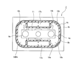
- FIG. 2 is a schematic cross-sectional view along the line AA in FIG. 1.
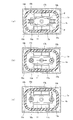
- FIG. 3 is a cross-sectional view taken along line BB in FIG. It is explanatory drawing with which it uses for description of arc extinguishing by the permanent magnet for arc extinguishing.
- It is typical sectional drawing which shows the modification of the 1st Embodiment of this invention.
- It is typical sectional drawing which shows the other modification of the 1st Embodiment of this invention.
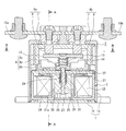
- FIG. 1 is a sectional view showing an example in which the contact device of the present invention is applied to an electromagnetic contactor as an electromagnetic switch.
- 1 is an exterior case made of, for example, a synthetic resin.
- the exterior case 1 includes a bottomed cylindrical body 1a whose lower end surface is opened and a bottom plate 1b that closes the lower end surface of the bottomed cylindrical body 1a.
- a contact device 2 having a contact mechanism and an electromagnet unit 3 as an electromagnet device for driving the contact device 2 are accommodated in a relationship in which the electromagnet unit 3 is arranged on the bottom plate 1b.
- the contact device 2 has an arc extinguishing container 4.
- the arc extinguishing container 4 is a bowl-shaped body 4a having a lower end formed of ceramics, synthetic resin or the like. And a metal joining member 4b that is tightly fixed to the open end surface thereof, and a metal cylinder 4c that covers the side surface of the bowl-shaped body 4a.
- the joining member 4b is fixed to the upper surface of the upper magnetic yoke 22 of the electromagnet unit 3 in an airtight state by brazing, welding, or the like.
- each of the fixed contacts 6 a and 6 b is composed of an upper-side large-diameter head 7 and a lower-side small-diameter cylindrical portion 8 that is coaxially connected to the large-diameter head 7.
- These fixed contacts 6a, 6b seal the through holes 5a, 5b by brazing, adhesive, or the like to the rod-like body 4a in a state where the small-diameter cylindrical portion 8 is inserted into the through-holes 5a, 5b of the rod-like body 4a. It is fixed to.
- the movable contact 11 is opposed to the lower end surfaces of the small-diameter cylindrical portions 8 of the fixed contacts 6a and 6b so that the movable contact 11 can be contacted and separated with a relatively narrow predetermined gap.
- the movable contact 11 has a flat surface 11a formed at least at a position facing the fixed contacts 6a and 6b.
- the movable contact 11 is formed with an arc foot movement promoting portion 12 in a direction orthogonal to the longitudinal direction of the movable contact 11 on the flat surface 11a, that is, on the front and rear end side.
- the arc foot movement promoting portion 12 is composed of inclined surfaces, that is, tapered surfaces 12 a and 12 b, whose thickness gradually decreases from the front and rear end portions of the flat surface 11 a toward the front and rear end portions of the movable contact 11.
- the movable contact 11 is attached to the contact holder 13 by being urged upward by a contact spring 14.
- the contact holder 13 is connected to a movable iron core 25 of the electromagnet unit 3 described later and is driven in the vertical direction.
- external connection terminal plates 15a and 15b are screwed to the large-diameter heads 7 of the fixed contacts 6a and 6b.
- magnet housing cylinder portions 16a and 16b are formed on the inner peripheral surface of the bowl-shaped body 4a facing the side surface orthogonal to the longitudinal direction of the movable contact 11, and these magnet housing cylinder portions 16a and 16a are formed.
- the arc extinguishing permanent magnets 17a and 17b are accommodated in 16b. These arc extinguishing permanent magnets 17a and 17b are magnetized such that the inner peripheral surfaces facing each other are N poles and the outer peripheral surfaces are magnetized S poles.
- the left and right spaces of the magnet housing cylinder portions 16a and 16b are arc extinguishing spaces 18a and 18b, respectively.
- a gas such as hydrogen gas, nitrogen gas, a mixed gas of hydrogen and nitrogen, air, SF 6 or the like is sealed in the arc extinguishing container 4 including the bowl-shaped body 4a, the joining member 4b, and the metal cylinder 4c.
- the electromagnet unit 3 has a U-shaped magnetic yoke 21 as viewed from the side, and a cylindrical portion 21 b having a lower end opened at the center of the bottom plate portion 21 a of the magnetic yoke 21.
- the upper surface side of the magnetic yoke 21 is connected by the upper magnetic yoke 22.
- a coil holder 24 around which an exciting coil 23 is wound is mounted on the outer peripheral surface of the cylindrical portion 21b of the magnetic yoke 21, and a bottomed cylindrical shape in which a movable iron core 25 is slidably mounted on the inner peripheral surface of the cylindrical portion 21b.
- a cap 26 is provided.
- a rubber seat 27 that contacts the bottom surface of the movable iron core 25 and absorbs an impact when the movable iron core 25 is lowered is disposed on the bottom surface of the cap 26.
- a connecting shaft 28 is fitted to the center of the movable iron core 25, and the head of the connecting shaft 28 extends upward through a through hole 29 formed in the upper magnetic yoke 22 and is connected to the contact holder 13. Yes. Further, a spring insertion hole 30 is formed around the connecting shaft 28 of the movable iron core 25, and a return spring 31 for biasing the movable iron core 25 downward is mounted between the spring insertion hole 30 and the upper magnetic yoke 22. Yes.
- the external connection terminal plate 15a is connected to a power supply source that supplies a large current, for example, and the external connection terminal plate 15b is connected to a load.
- the excitation coil 23 in the electromagnet unit 3 is in a non-energized state and no excitation force for moving the movable iron core 25 by the electromagnet unit 3 is generated.
- the movable iron core 25 is urged downward by the return spring 31 away from the upper magnetic yoke 22 and comes into contact with the rubber seat 27.
- the movable contact 11 supported by the contact holder 13 connected to the movable iron core 25 via the connecting shaft 28 sandwiches a predetermined gap from the lower end surface of the small diameter cylindrical portion 8 of the fixed contacts 6a and 6b.
- the contact device 2 is in an open (released) state.
- a closed state (input) state in which a large current i of the external power supply source is supplied to the load through the external connection terminal plate 15a, the fixed contact 6a, the movable contact 11, the fixed contact 6b, and the external connection terminal plate 15b. It becomes.
- the current supply to the load is cut off from the closed state of the contact device 2, the voltage application to the exciting coil 23 of the electromagnet unit 3 is stopped.
- the exciting force that moves the movable iron core 25 upward by the electromagnet unit 3 disappears, and the movable iron core 25 is lowered by the biasing force of the return spring 31.
- the contact holder 13 connected via the connecting shaft 28 is lowered.
- the movable contact 11 is in contact with the fixed contacts 6a and 6b while a contact pressure is applied by the contact spring 14 in accordance with the lowering of the contact holder 13. Thereafter, when the contact pressure of the contact spring 14 disappears, the movable contact 11 is brought into a contact opening start state in which the movable contact 11 is separated downward from the fixed contacts 6a and 6b.
- the arc generating portion of the contact portion of the fixed contact 6b and the contact portion of the movable contact 11 traverses in the longitudinal direction of the movable contact 11 from the inside to the outside and reaches the S pole to form a magnetic field. Therefore, the magnetic fluxes of the arc extinguishing permanent magnets 17a and 17b are both opposite to each other in the longitudinal direction of the movable contact 11 between the fixed contact 6a and the movable contact 11 and between the fixed contact 6b and the movable contact 11. Will cross.
- This Lorentz force F causes an arc generated between the stationary contact 6a and the movable contact 11 to reach the lower surface side of the movable contact 11 from the side surface of the stationary contact 6a through the arc extinguishing space 18b. Is greatly stretched to extinguish the arc. Further, in the arc extinguishing space 18b, the direction of the magnetic flux between the fixed contact 6a and the movable contact 11 is uniform on the lower side and the upper side, and the current direction differs depending on the extension of the arc.
- the arc stretched in the arc extinguishing space 18b is stretched so that it further spreads in the direction of the corner of the arc extinguishing space 18b, the arc length can be lengthened, and good interrupting performance can be achieved. Obtainable.
- the arc generated between the fixed contact 6b and the movable contact 11 by this Lorentz force F reaches the side of the fixed contact 6b from the upper surface side of the movable contact 11 through the arc extinguishing space 18b.
- the direction of the magnetic flux between the fixed contact 6b and the movable contact 11 is uniform on the lower side and the upper side, and the direction of the current is caused by the extension of the arc. Different.
- the arc stretched in the arc extinguishing space 18b by the direction of the current is further stretched in the direction of the corner of the arc extinguishing space 18b, the arc length can be increased, and good interruption performance can be obtained. .
- the distance between the arc leg of the taper surface 12a or 12b of the movable contact 11 and the other leg of the arc formed on the fixed contacts 6a and 6b is increased, which is affected by metal vapor or the like. Without increasing the electric field strength. For this reason, it is possible to reliably prevent a re-occurring arc from occurring between the electrodes in the vicinity of the arc foot of the movable contact 11 and improve the interruption performance.
- the movable contact 11 is a flat surface on which the tapered surfaces 12a and 12b are not formed, an arc generated between the movable contact 11 and the fixed contacts 6a and 6b on the movable contact 11 side.
- the arc leg is stretched toward the arc extinguishing space 18b by the magnetic force of the arc extinguishing permanent magnets 17a and 17b, the arc leg remains at the corner between the flat surface and the side surface.
- the electric field strength between the arc legs may be lowered to an arc voltage or less due to metal vapor or the like.
- a recurring arc is generated between the electrodes in the vicinity of the arc foot, and the interruption performance is reduced.
- the arc foot can easily move to the surface of the movable contact 11 opposite to the fixed contacts 6a and 6b and can easily extend. Therefore, the blocking performance can be further improved.
- the arc foot movement promoting portion 12 including the tapered surfaces 12a and 12b is formed on the side surface orthogonal to the longitudinal direction of the movable contact 11, the movable contact 11 is fixed. It is possible to easily move the foot on the movable contact side of the arc generated at the time of opening apart from the contacts 6a and 6b along the tapered surface 12a (or 12b).
- the distance between the arc legs generated between the movable contact 11 and the fixed contacts 6a and 6b is increased to increase the electric field strength, thereby preventing re-arcing and quickening the arc extinction to improve the interruption performance. be able to.
- the gap between the fixed contacts 6a and 6b and the movable contact 11 can be narrowed, and the opening time for cutting off the current can be shortened. it can.
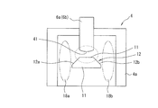
- the portion of the fixed contacts 6a and 6b facing the movable contact 11 is the small-diameter cylindrical portion 8.
- the present invention is not limited to this.
- the contact portions of the fixed contacts 6a and 6b facing the movable contact 11 may be formed on the curved surface 41 having a spherical or cylindrical shape.
- the legs of the arc also move upward on the fixed contacts 6a and 6b side, the distance between the arc legs can be made longer, and the arc is extinguished more reliably and the interruption performance. Can be further improved.
- the arc leg movement promotion part 12 was formed in taper surface 12a, 12b was demonstrated, it is not limited to this, As shown in FIG.
- the arcuate curved surfaces 42a and 42b that form a part of the curved surface may be used. In this case, as the arc foot moves outward along the arcuate curved surfaces 42a and 42b, the distance between the stationary contact 6a and 6b and the arc foot can be increased, and the interruption performance is further improved. Can be made.
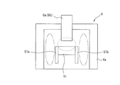
- an arc runner is provided as an arc foot movement promoting portion instead of the inclined surface. That is, in the second embodiment, as shown in FIG. 7, an arc runner 51 a that covers the side surface in a direction orthogonal to the longitudinal direction of the movable contact 11 having a rectangular cross section and extends downward from the lower surface of the movable contact 11, 52b is fixed.
- each of the arc runners 51a and 51b may be formed of an arc-resistant material such as tungsten (W) or silver (Ag), or a metal material having conductivity such as copper (Cu).
- the arc leg on the movable contactor 11 side moves to the side of the arc runner 51a (or 51b) as the arc leg is extended to the arc extinguishing space 18a (or 18b) side, and the arc leg moves to the arc runner.
- 51a (or 51b) it will rapidly move downward along this arc runner 51a (or 51b).
- the legs of the arc do not stay at the corners of the side surface of the movable contact 11, and the distance between the fixed contacts 6a and 6b and the legs of the arc is lengthened to prevent the electric field strength from being lowered due to metal vapor or the like. be able to. Therefore, the arc can be easily extinguished and the interruption performance can be improved.
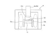
- the present invention is not limited to this, and both arc runners 51a and 51b are used.
- the upper end portions may be connected by a connecting portion 51c to form an inverted U-shaped cross section.
- a groove 52 extending in the front-rear direction is formed on the surface of the movable contact 11 facing the fixed contacts 6a and 6b, and the connecting portion 51c is engaged with and fixed to the groove 52.
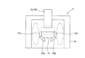
- an arc runner 53 formed in an inverted U shape may be fixed to the lower surface side of the movable contact 11. Even in this case, when the arc is stretched by the arc extinguishing permanent magnets 17a and 17b and reaches the end portion on the side surface side of the movable contact 11, the arc foot does not stay at the end portion, but on the lower surface side. It is drawn to the formed arc runner 53. For this reason, the distance between the arc leg on the movable contact 11 side and the arc leg of the fixed contacts 6a and 6b can be lengthened, and the electric field strength between the arc legs can be increased to improve the interruption performance.
- the arc runners 54a and 54b on the lower surface side of the movable contactor 11 may be bent inward and inclined inward.
- the arc foot of the movable contact 11 can be moved to the lower surface side of the movable contact 11, and the lower side of the movable contact 11 can be used as an arc extinguishing space.
- the stretched length can be increased to facilitate arc extinction, and the volume can be effectively used.
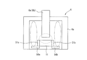
- the arc runners 55a and 55b on the lower side of the movable contactor 11 may be bent outward and inclined outward as opposed to FIG. In this case, the arc foot can be moved in the direction in which the arc is easily spread on the lower surface side of the movable contact 11. The arc foot can be moved reliably and the arc can be easily extinguished.
- the arc runners 56a and 56b on the lower side of the movable contactor 11 may be bent outward in a right angle direction and protrude outward. Also in this case, similarly to FIG. 11, the arc foot can be moved in the direction in which the arc easily spreads on the lower surface side of the movable contact 11, and the arc foot can be reliably moved to easily extinguish the arc. be able to.
- the surfaces of the fixed contacts 6a and 6b facing the movable contact 11 are formed in a spherical shape or a cylindrical surface shape. Also good.
- the arc extinguishing permanent magnets 17a and 17b are arranged inside the rod-shaped body 4a.
- the arc permanent magnets 17a and 17b may be arranged outside the bowl-shaped body 4a in parallel with the movable contactor 11.
- the said 1st and 2nd embodiment demonstrated the case where the arc-extinguishing container 4 was comprised by the rod-shaped body 4a, the joining member 4b, and the metal cylinder 4c, it is not limited to this, A metal An insulating cylinder may be arranged inside the made cage, and any configuration can be adopted.
- the case where gas is sealed in the arc extinguishing container 4 has been described.
- the present invention is not limited to this, and when the current value to be cut off is small, the gas is sealed. Can be omitted.
- the movable contact 11 may be formed in flat form in the longitudinal direction, it is not limited to this,
- the movable contact 11 The central part between the contact parts facing the fixed contacts 6a, 6b may be formed in a concave or convex shape.
- the fixed contact 6a And 6b may be arranged on the lower side of the arc extinguishing container 4, and the movable contact 11 may be opposed to the contact parts from the upper side.
- the configuration of the electromagnet unit 3 is not limited to the above embodiment, and any configuration can be applied as long as the contact holder 13 can be moved by electromagnetic force. Furthermore, in the said embodiment, although the case where the contact apparatus 2 of this invention was applied to an electromagnetic contactor was demonstrated, it is not limited to this, Arbitrary switches including an electromagnetic relay and another electromagnetic switch Can be applied to.
- the arc foot movement promoting part is formed that moves the foot of the arc generated when the movable contact is opened in a direction away from the fixed contact. Therefore, it is possible to provide a contact device that can easily extinguish an arc generated between the fixed contact and the movable contact at the time of opening, and an electromagnetic switch using the contact device.
Abstract
L'invention concerne un dispositif contact et un contacteur électromagnétique utilisant ledit dispositif contact qui sont capables d'éteindre facilement un arc produit entre un élément de contact fixe et un élément de contact mobile lorsque ledit dispositif contact est ouvert. Ledit dispositif contact comprend : une paire d'éléments de contact fixe (6a, 6b) qui, en maintenant un intervalle spécifié, sont fixés en place dans une chambre d'extinction d'arc; et l'élément de contact mobile (11), qui est agencé de façon à permettre la fixation à la paire d'éléments de contact fixe ou la séparation de celle-ci. Une section d'encouragement de mouvement de l'origine de l'arc (12) est formée sur l'élément de contact mobile (11), ladite section d'encouragement de mouvement de l'origine de l'arc (12) encourageant le mouvement de l'origine de l'arc produit lorsque le dispositif contact est ouvert, moment auquel l'élément de contact mobile se sépare de la paire d'éléments de contact fixe.
Priority Applications (4)
| Application Number | Priority Date | Filing Date | Title |
|---|---|---|---|
| CN201380018926.7A CN104221115B (zh) | 2012-04-13 | 2013-04-11 | 触点装置和使用它的电磁开关 |
| EP13776087.2A EP2838099A4 (fr) | 2012-04-13 | 2013-04-11 | Dispositif contact et contacteur électromagnétique l'utilisant |
| KR1020147027928A KR20140145143A (ko) | 2012-04-13 | 2013-04-11 | 접점 장치 및 이것을 사용한 전자 개폐기 |
| US14/505,680 US9508509B2 (en) | 2012-04-13 | 2014-10-03 | Contact device having arc root movement promotion portion, and electromagnetic switch in which the contact device is used |
Applications Claiming Priority (2)
| Application Number | Priority Date | Filing Date | Title |
|---|---|---|---|
| JP2012092451A JP5990028B2 (ja) | 2012-04-13 | 2012-04-13 | 接点装置及びこれを使用した電磁開閉器 |
| JP2012-092451 | 2012-04-13 |
Related Child Applications (1)
| Application Number | Title | Priority Date | Filing Date |
|---|---|---|---|
| US14/505,680 Continuation US9508509B2 (en) | 2012-04-13 | 2014-10-03 | Contact device having arc root movement promotion portion, and electromagnetic switch in which the contact device is used |
Publications (1)
| Publication Number | Publication Date |
|---|---|
| WO2013153818A1 true WO2013153818A1 (fr) | 2013-10-17 |
Family
ID=49327402
Family Applications (1)
| Application Number | Title | Priority Date | Filing Date |
|---|---|---|---|
| PCT/JP2013/002474 WO2013153818A1 (fr) | 2012-04-13 | 2013-04-11 | Dispositif contact et contacteur électromagnétique l'utilisant |
Country Status (6)
| Country | Link |
|---|---|
| US (1) | US9508509B2 (fr) |
| EP (1) | EP2838099A4 (fr) |
| JP (1) | JP5990028B2 (fr) |
| KR (1) | KR20140145143A (fr) |
| CN (1) | CN104221115B (fr) |
| WO (1) | WO2013153818A1 (fr) |
Cited By (1)
| Publication number | Priority date | Publication date | Assignee | Title |
|---|---|---|---|---|
| CN106229179A (zh) * | 2016-08-03 | 2016-12-14 | 太仓美宅姬娱乐传媒有限公司 | 一种采用拨叉消弧的电磁开关 |
Families Citing this family (37)
| Publication number | Priority date | Publication date | Assignee | Title |
|---|---|---|---|---|
| JP5965197B2 (ja) | 2012-04-13 | 2016-08-03 | 富士電機機器制御株式会社 | 開閉器 |
| KR101698421B1 (ko) * | 2012-12-06 | 2017-01-20 | 후지 덴키 기기세이교 가부시끼가이샤 | 접점 장치 및 이것을 사용한 전자 개폐기 |
| JP6064223B2 (ja) * | 2012-12-28 | 2017-01-25 | パナソニックIpマネジメント株式会社 | 接点装置および当該接点装置を搭載した電磁継電器 |
| CN105359243B (zh) | 2013-06-28 | 2018-06-05 | 松下知识产权经营株式会社 | 触点装置以及搭载有该触点装置的电磁继电器 |
| CN105793951B (zh) * | 2014-05-20 | 2017-10-10 | 富士电机机器制御株式会社 | 电磁接触器 |
| KR101592271B1 (ko) * | 2014-06-30 | 2016-02-11 | 현대중공업 주식회사 | 전자접촉기 |
| KR200486468Y1 (ko) * | 2014-09-29 | 2018-07-05 | 엘에스산전 주식회사 | 직류 릴레이 |
| JP6548905B2 (ja) * | 2015-02-06 | 2019-07-24 | 富士通コンポーネント株式会社 | スイッチ |
| CN104779102A (zh) | 2015-03-25 | 2015-07-15 | 敬德强 | 新型大电流簧片式开关触点结构 |
| JP6528271B2 (ja) * | 2015-04-13 | 2019-06-12 | パナソニックIpマネジメント株式会社 | 接点装置および電磁継電器 |
| KR101961661B1 (ko) * | 2015-07-31 | 2019-03-26 | 엘에스산전 주식회사 | 고전압 릴레이 장치 |
| JP6536472B2 (ja) * | 2016-04-28 | 2019-07-03 | 株式会社デンソー | ソレノイド |
| JP6668997B2 (ja) * | 2016-07-29 | 2020-03-18 | オムロン株式会社 | 電磁継電器 |
| JP6828294B2 (ja) * | 2016-07-29 | 2021-02-10 | オムロン株式会社 | 電磁継電器 |
| CN106710969A (zh) * | 2017-02-09 | 2017-05-24 | 苏州安来强电子科技有限公司 | 带引弧角的密封型接触器 |
| JP6801629B2 (ja) * | 2017-10-31 | 2020-12-16 | オムロン株式会社 | 電磁継電器 |
| JP2019083174A (ja) * | 2017-10-31 | 2019-05-30 | オムロン株式会社 | 電磁継電器 |
| JP6919504B2 (ja) * | 2017-10-31 | 2021-08-18 | オムロン株式会社 | 電磁継電器 |
| CN108231441B (zh) * | 2018-03-12 | 2024-02-20 | 西安开天铁路电气股份有限公司 | 一种触头结构 |
| DE102018109403A1 (de) * | 2018-04-19 | 2019-10-24 | Tdk Electronics Ag | Schaltvorrichtung |
| KR102324514B1 (ko) * | 2018-08-31 | 2021-11-10 | 엘에스일렉트릭 (주) | 직류 릴레이 |
| KR20200000311A (ko) * | 2018-08-31 | 2020-01-02 | 엘에스산전 주식회사 | 직류 릴레이 |
| KR102652524B1 (ko) * | 2018-11-09 | 2024-03-29 | 샤먼 홍파 일렉트릭 파워 컨트롤즈 컴퍼니 리미티드 | 단락전류 방지용 직류 릴레이 |
| JP7142219B2 (ja) * | 2018-11-13 | 2022-09-27 | パナソニックIpマネジメント株式会社 | 接点装置及び電磁継電器 |
| JP7142220B2 (ja) * | 2018-11-13 | 2022-09-27 | パナソニックIpマネジメント株式会社 | 接点装置及び電磁継電器 |
| JP7206831B2 (ja) * | 2018-11-16 | 2023-01-18 | オムロン株式会社 | 接点装置 |
| JP7056549B2 (ja) * | 2018-12-28 | 2022-04-19 | オムロン株式会社 | 電磁継電器 |
| JP7036047B2 (ja) * | 2019-01-18 | 2022-03-15 | オムロン株式会社 | リレー |
| JP7310474B2 (ja) * | 2019-09-13 | 2023-07-19 | オムロン株式会社 | リレー |
| JP7351157B2 (ja) | 2019-09-18 | 2023-09-27 | オムロン株式会社 | リレー |
| EP3951825B1 (fr) * | 2019-11-18 | 2023-06-21 | Fuji Electric FA Components & Systems Co., Ltd. | Unité de contact auxiliaire |
| CN211208340U (zh) * | 2019-12-04 | 2020-08-07 | Ls产电株式会社 | 电弧路径形成部及包括其的直流继电器 |
| JP7443842B2 (ja) * | 2020-03-11 | 2024-03-06 | オムロン株式会社 | 電磁継電器 |
| JP2022069864A (ja) * | 2020-10-26 | 2022-05-12 | オムロン株式会社 | 電磁継電器 |
| JP2023025545A (ja) * | 2021-08-10 | 2023-02-22 | 富士電機機器制御株式会社 | 電磁接触器 |
| DE102022110496B4 (de) * | 2022-04-29 | 2023-12-21 | Tdk Electronics Ag | Schaltvorrichtung |
| JP2024014554A (ja) | 2022-07-22 | 2024-02-01 | オムロン株式会社 | 電磁継電器 |
Citations (2)
| Publication number | Priority date | Publication date | Assignee | Title |
|---|---|---|---|---|
| JP2002334644A (ja) * | 2001-05-10 | 2002-11-22 | Toyota Motor Corp | 電磁継電器 |
| JP2006019148A (ja) | 2004-07-01 | 2006-01-19 | Matsushita Electric Works Ltd | 電磁開閉装置 |
Family Cites Families (9)
| Publication number | Priority date | Publication date | Assignee | Title |
|---|---|---|---|---|
| US5519370A (en) | 1991-03-28 | 1996-05-21 | Kilovac Corporation | Sealed relay device |
| JP3321963B2 (ja) * | 1994-02-22 | 2002-09-09 | 株式会社デンソー | プランジャ型電磁継電器 |
| US5680084A (en) * | 1994-11-28 | 1997-10-21 | Matsushita Electric Works, Ltd. | Sealed contact device and operating mechanism |
| JP3228105B2 (ja) * | 1995-12-11 | 2001-11-12 | 富士電機株式会社 | 電気接点 |
| JP4241300B2 (ja) * | 2003-09-29 | 2009-03-18 | 株式会社デンソー | スタータ用電磁スイッチ |
| CN101978453B (zh) * | 2008-03-19 | 2013-11-13 | 松下电器产业株式会社 | 接点装置 |
| JP5197480B2 (ja) * | 2009-05-14 | 2013-05-15 | 株式会社日本自動車部品総合研究所 | 電磁継電器 |
| KR101681591B1 (ko) * | 2010-01-25 | 2016-12-01 | 엘에스산전 주식회사 | 전자 개폐기 |
| JP5573250B2 (ja) * | 2010-03-09 | 2014-08-20 | オムロン株式会社 | 封止接点装置 |
-
2012
- 2012-04-13 JP JP2012092451A patent/JP5990028B2/ja not_active Expired - Fee Related
-
2013
- 2013-04-11 KR KR1020147027928A patent/KR20140145143A/ko not_active Application Discontinuation
- 2013-04-11 CN CN201380018926.7A patent/CN104221115B/zh not_active Expired - Fee Related
- 2013-04-11 EP EP13776087.2A patent/EP2838099A4/fr not_active Withdrawn
- 2013-04-11 WO PCT/JP2013/002474 patent/WO2013153818A1/fr active Application Filing
-
2014
- 2014-10-03 US US14/505,680 patent/US9508509B2/en active Active
Patent Citations (2)
| Publication number | Priority date | Publication date | Assignee | Title |
|---|---|---|---|---|
| JP2002334644A (ja) * | 2001-05-10 | 2002-11-22 | Toyota Motor Corp | 電磁継電器 |
| JP2006019148A (ja) | 2004-07-01 | 2006-01-19 | Matsushita Electric Works Ltd | 電磁開閉装置 |
Non-Patent Citations (1)
| Title |
|---|
| See also references of EP2838099A4 |
Cited By (1)
| Publication number | Priority date | Publication date | Assignee | Title |
|---|---|---|---|---|
| CN106229179A (zh) * | 2016-08-03 | 2016-12-14 | 太仓美宅姬娱乐传媒有限公司 | 一种采用拨叉消弧的电磁开关 |
Also Published As
| Publication number | Publication date |
|---|---|
| US9508509B2 (en) | 2016-11-29 |
| EP2838099A4 (fr) | 2015-12-30 |
| JP2013222562A (ja) | 2013-10-28 |
| US20150022291A1 (en) | 2015-01-22 |
| JP5990028B2 (ja) | 2016-09-07 |
| EP2838099A1 (fr) | 2015-02-18 |
| CN104221115B (zh) | 2016-12-28 |
| KR20140145143A (ko) | 2014-12-22 |
| CN104221115A (zh) | 2014-12-17 |
Similar Documents
| Publication | Publication Date | Title |
|---|---|---|
| JP5990028B2 (ja) | 接点装置及びこれを使用した電磁開閉器 | |
| JP5986419B2 (ja) | 接点装置及びこれを使用した電磁開閉器 | |
| JP5856426B2 (ja) | 接点装置及びこれを使用した電磁接触器 | |
| JP5437949B2 (ja) | 接点装置及びこれを使用した電磁接触器 | |
| JP5809443B2 (ja) | 接点機構及びこれを使用した電磁接触器 | |
| JP6081787B2 (ja) | 接点装置及びこれを使用した電磁開閉器 | |
| JP5768223B2 (ja) | 接点装置 | |
| WO2012020529A1 (fr) | Dispositif à contacts et commutateur électromagnétique utilisant ce dispositif | |
| WO2012029218A1 (fr) | Commutateur électromagnétique | |
| JP6359896B2 (ja) | 接点機構及びこれを使用した電磁接触器 | |
| KR20150004805A (ko) | 개폐기 | |
| JP2016012505A (ja) | 接点機構及びこれを使用した電磁接触器 | |
| JP5629108B2 (ja) | 接点装置 | |
| JP2013246873A (ja) | 接点装置 | |
| JP2016134308A (ja) | 電磁接触器 | |
| JP5990281B2 (ja) | 接点装置及びこれを使用した電磁開閉器 | |
| CN113785378A (zh) | 直流继电器 | |
| JP6291871B2 (ja) | 接点装置及びこれを使用した電磁接触器 | |
| JP5942276B2 (ja) | 接点装置 | |
| JP7077890B2 (ja) | 接点機構及びこれを使用した電磁接触器 | |
| JP2022139892A (ja) | 電磁接触器 | |
| JP2023552893A (ja) | 永久磁石消弧付きの高圧直流リレー | |
| JP2015028934A (ja) | 接点装置およびこれを使用した電磁接触器 | |
| JP2021057319A (ja) | 接点機構及びこれを使用した電磁接触器 |
Legal Events
| Date | Code | Title | Description |
|---|---|---|---|
| 121 | Ep: the epo has been informed by wipo that ep was designated in this application |
Ref document number: 13776087 Country of ref document: EP Kind code of ref document: A1 |
|
| ENP | Entry into the national phase |
Ref document number: 20147027928 Country of ref document: KR Kind code of ref document: A |
|
| WWE | Wipo information: entry into national phase |
Ref document number: 2013776087 Country of ref document: EP |
|
| NENP | Non-entry into the national phase |
Ref country code: DE |