WO2013153818A1 - Contact device and electromagnetic switch using same - Google Patents
Contact device and electromagnetic switch using same Download PDFInfo
- Publication number
- WO2013153818A1 WO2013153818A1 PCT/JP2013/002474 JP2013002474W WO2013153818A1 WO 2013153818 A1 WO2013153818 A1 WO 2013153818A1 JP 2013002474 W JP2013002474 W JP 2013002474W WO 2013153818 A1 WO2013153818 A1 WO 2013153818A1
- Authority
- WO
- WIPO (PCT)
- Prior art keywords
- arc
- contact
- movable contact
- movable
- fixed
- Prior art date
Links
Images


Classifications
-
- H—ELECTRICITY
- H01—ELECTRIC ELEMENTS
- H01H—ELECTRIC SWITCHES; RELAYS; SELECTORS; EMERGENCY PROTECTIVE DEVICES
- H01H33/00—High-tension or heavy-current switches with arc-extinguishing or arc-preventing means
- H01H33/02—Details
- H01H33/04—Means for extinguishing or preventing arc between current-carrying parts
- H01H33/20—Means for extinguishing or preventing arc between current-carrying parts using arcing horns
-
- H—ELECTRICITY
- H01—ELECTRIC ELEMENTS
- H01H—ELECTRIC SWITCHES; RELAYS; SELECTORS; EMERGENCY PROTECTIVE DEVICES
- H01H1/00—Contacts
- H01H1/06—Contacts characterised by the shape or structure of the contact-making surface, e.g. grooved
-
- H—ELECTRICITY
- H01—ELECTRIC ELEMENTS
- H01H—ELECTRIC SWITCHES; RELAYS; SELECTORS; EMERGENCY PROTECTIVE DEVICES
- H01H3/00—Mechanisms for operating contacts
- H01H3/22—Power arrangements internal to the switch for operating the driving mechanism
- H01H3/28—Power arrangements internal to the switch for operating the driving mechanism using electromagnet
-
- H—ELECTRICITY
- H01—ELECTRIC ELEMENTS
- H01H—ELECTRIC SWITCHES; RELAYS; SELECTORS; EMERGENCY PROTECTIVE DEVICES
- H01H33/00—High-tension or heavy-current switches with arc-extinguishing or arc-preventing means
- H01H33/02—Details
- H01H33/04—Means for extinguishing or preventing arc between current-carrying parts
- H01H33/18—Means for extinguishing or preventing arc between current-carrying parts using blow-out magnet
- H01H33/182—Means for extinguishing or preventing arc between current-carrying parts using blow-out magnet using permanent magnets
-
- H—ELECTRICITY
- H01—ELECTRIC ELEMENTS
- H01H—ELECTRIC SWITCHES; RELAYS; SELECTORS; EMERGENCY PROTECTIVE DEVICES
- H01H50/00—Details of electromagnetic relays
- H01H50/16—Magnetic circuit arrangements
- H01H50/36—Stationary parts of magnetic circuit, e.g. yoke
- H01H50/38—Part of main magnetic circuit shaped to suppress arcing between the contacts of the relay
-
- H—ELECTRICITY
- H01—ELECTRIC ELEMENTS
- H01H—ELECTRIC SWITCHES; RELAYS; SELECTORS; EMERGENCY PROTECTIVE DEVICES
- H01H50/00—Details of electromagnetic relays
- H01H50/54—Contact arrangements
- H01H50/546—Contact arrangements for contactors having bridging contacts
-
- H—ELECTRICITY
- H01—ELECTRIC ELEMENTS
- H01H—ELECTRIC SWITCHES; RELAYS; SELECTORS; EMERGENCY PROTECTIVE DEVICES
- H01H73/00—Protective overload circuit-breaking switches in which excess current opens the contacts by automatic release of mechanical energy stored by previous operation of a hand reset mechanism
- H01H73/02—Details
- H01H73/04—Contacts
- H01H73/045—Bridging contacts
-
- H—ELECTRICITY
- H01—ELECTRIC ELEMENTS
- H01H—ELECTRIC SWITCHES; RELAYS; SELECTORS; EMERGENCY PROTECTIVE DEVICES
- H01H9/00—Details of switching devices, not covered by groups H01H1/00 - H01H7/00
- H01H9/30—Means for extinguishing or preventing arc between current-carrying parts
- H01H9/44—Means for extinguishing or preventing arc between current-carrying parts using blow-out magnet
- H01H9/443—Means for extinguishing or preventing arc between current-carrying parts using blow-out magnet using permanent magnets
-
- H—ELECTRICITY
- H01—ELECTRIC ELEMENTS
- H01H—ELECTRIC SWITCHES; RELAYS; SELECTORS; EMERGENCY PROTECTIVE DEVICES
- H01H9/00—Details of switching devices, not covered by groups H01H1/00 - H01H7/00
- H01H9/30—Means for extinguishing or preventing arc between current-carrying parts
- H01H9/46—Means for extinguishing or preventing arc between current-carrying parts using arcing horns
-
- H—ELECTRICITY
- H01—ELECTRIC ELEMENTS
- H01H—ELECTRIC SWITCHES; RELAYS; SELECTORS; EMERGENCY PROTECTIVE DEVICES
- H01H50/00—Details of electromagnetic relays
- H01H50/02—Bases; Casings; Covers
- H01H50/023—Details concerning sealing, e.g. sealing casing with resin
- H01H2050/025—Details concerning sealing, e.g. sealing casing with resin containing inert or dielectric gasses, e.g. SF6, for arc prevention or arc extinction
Definitions
- the present invention relates to a contact device including a stationary contact and a movable contact inserted in a current path and an electromagnetic switch using the contact device, and occurs when the stationary contact and the movable contact are opened, that is, when a current is interrupted. The arc is extinguished easily.
- a pair of fixed contacts each having a fixed contact disposed at a predetermined distance away from each other, and a movable contact having a movable contact at left and right ends disposed so as to be able to contact with and separate from the pair of fixed contacts
- An electromagnetic switching device comprising an electromagnet device for driving the movable contact and an enclosing member for housing the movable contact and the stationary contact, and an arc extinguishing permanent magnet arranged in parallel to the moveable contact on the outside of the enclosing member
- the present invention has been made paying attention to the unsolved problems of the above-described conventional example, and a contact device that can easily extinguish an arc generated between a fixed contact and a movable contact at the time of opening. And it aims at providing the electromagnetic switch using this.
- a first aspect of the contact device includes a pair of fixed contacts fixedly arranged in the arc extinguishing chamber at a predetermined interval, and the pair of fixed contacts. And a movable contact arranged so as to be able to contact and separate.
- the movable contact is provided with an arc foot movement promoting portion that promotes movement of an arc foot generated at the time of opening away from the pair of fixed contacts in a direction away from the fixed contact. .
- an arc is generated between the movable contact and the pair of fixed contacts when the movable contact is separated from the pair of fixed contacts.
- the arc foot movement promoting portion is formed on the movable contact, the arc foot generated by the arc foot movement promoting portion can be moved away from the fixed contact without staying at the corner. . Therefore, the electric field strength at the time of arc generation becomes large, and it is possible to suppress the recurrence of the arc and improve the interruption performance.
- a second aspect of the contact device is an inclined surface in which the arc foot movement promoting portion becomes thinner as it goes to the end portion in a direction perpendicular to the current flow direction of the movable contact. It is configured. According to the second aspect, since the inclined surface such as the tapered surface or the arc surface whose thickness decreases as it goes to the step portion in the direction orthogonal to the current flow direction of the movable contact, the inclined surface is formed. The downward movement of the arc foot is promoted.
- the said inclined surface is comprised by the taper surface.
- the inclined surface is a tapered surface, it is possible to easily form the movable contact having the arc foot movement promoting portion.
- the inclined surface is formed by an arcuate curved surface. According to the fourth aspect, since the inclined surface is an arcuate curved surface, no corner is formed before the movable contactor reaches the bottom surface side, and the arc foot is easily and reliably moved. be able to.
- the 5th aspect of the contact apparatus which concerns on this invention is an opposite side to the said pair of stationary contact side which the said arc leg movement promotion part formed in the end surface orthogonal to the electric current flow direction of the said movable contact. It consists of an arc runner that protrudes and extends.
- an arc runner is provided as an arc leg movement promotion part, and this arc runner is projected and extended on the opposite side to a pair of fixed contacts of a movable contact. For this reason, since the legs of the arc generated at the time of opening are moved in the direction away from the fixed contact without staying at the corners, the electric field strength at the time of arc generation is increased to suppress recurring arcs and improve the breaking performance be able to.
- the 6th form of the contact apparatus which concerns on this invention is formed so that the said arc runner may cover the side surface of the said movable contact.
- the leg of the arc generated at the time of opening reaches the corner of the movable contact, it is surely moved downward along the arc runner, thereby improving the breaking performance. I can do it.
- the arc runner has an inwardly inclined protrusion on the side of the movable contact opposite to the pair of fixed contacts.
- the arc foot can be extended to the lower side of the movable contact, and the arc extinguishing can be performed.
- the space can be expanded and the volume can be used effectively.
- the arc runner is configured such that a protruding portion of the movable contact opposite to the pair of fixed contacts is inclined outward. According to the eighth aspect, since the arc runner is inclined outward on the lower side of the movable contact, the distance between the arc foot of the fixed contact is increased by extending the arc foot in a direction that is easy to spread. Can do.
- the arc runner has a protruding portion of the movable contact opposite to the pair of fixed contacts that extends outwardly. According to the ninth aspect, the arc runner can widen the arc leg outward and the distance between the fixed contact and the arc leg can be increased.
- a first aspect of the electromagnetic switch according to the present invention includes the contact device according to the first to ninth aspects, wherein the movable contact is connected to a movable iron core of an electromagnet device, and the fixed contact is externally provided. Connected to the connection terminal. According to this configuration, it is possible to provide an electromagnetic switch capable of improving the interrupting performance by reliably extinguishing an arc generated at the time of opening with a simple configuration.
- the contact device having the above effects to an electromagnetic switch, an electromagnetic contactor, an electromagnetic relay, etc. that can easily extinguish an arc generated at the time of opening with a simple configuration and improve a breaking performance.
- An electromagnetic switch can be provided.
- FIG. 2 is a schematic cross-sectional view along the line AA in FIG. 1.
- FIG. 3 is a cross-sectional view taken along line BB in FIG. It is explanatory drawing with which it uses for description of arc extinguishing by the permanent magnet for arc extinguishing.
- It is typical sectional drawing which shows the modification of the 1st Embodiment of this invention.
- It is typical sectional drawing which shows the other modification of the 1st Embodiment of this invention.
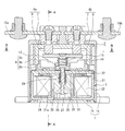
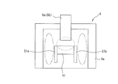
- FIG. 1 is a sectional view showing an example in which the contact device of the present invention is applied to an electromagnetic contactor as an electromagnetic switch.
- 1 is an exterior case made of, for example, a synthetic resin.
- the exterior case 1 includes a bottomed cylindrical body 1a whose lower end surface is opened and a bottom plate 1b that closes the lower end surface of the bottomed cylindrical body 1a.
- a contact device 2 having a contact mechanism and an electromagnet unit 3 as an electromagnet device for driving the contact device 2 are accommodated in a relationship in which the electromagnet unit 3 is arranged on the bottom plate 1b.
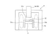
- the contact device 2 has an arc extinguishing container 4.
- the arc extinguishing container 4 is a bowl-shaped body 4a having a lower end formed of ceramics, synthetic resin or the like. And a metal joining member 4b that is tightly fixed to the open end surface thereof, and a metal cylinder 4c that covers the side surface of the bowl-shaped body 4a.
- the joining member 4b is fixed to the upper surface of the upper magnetic yoke 22 of the electromagnet unit 3 in an airtight state by brazing, welding, or the like.
- each of the fixed contacts 6 a and 6 b is composed of an upper-side large-diameter head 7 and a lower-side small-diameter cylindrical portion 8 that is coaxially connected to the large-diameter head 7.
- These fixed contacts 6a, 6b seal the through holes 5a, 5b by brazing, adhesive, or the like to the rod-like body 4a in a state where the small-diameter cylindrical portion 8 is inserted into the through-holes 5a, 5b of the rod-like body 4a. It is fixed to.
- the movable contact 11 is opposed to the lower end surfaces of the small-diameter cylindrical portions 8 of the fixed contacts 6a and 6b so that the movable contact 11 can be contacted and separated with a relatively narrow predetermined gap.
- the movable contact 11 has a flat surface 11a formed at least at a position facing the fixed contacts 6a and 6b.
- the movable contact 11 is formed with an arc foot movement promoting portion 12 in a direction orthogonal to the longitudinal direction of the movable contact 11 on the flat surface 11a, that is, on the front and rear end side.
- the arc foot movement promoting portion 12 is composed of inclined surfaces, that is, tapered surfaces 12 a and 12 b, whose thickness gradually decreases from the front and rear end portions of the flat surface 11 a toward the front and rear end portions of the movable contact 11.
- the movable contact 11 is attached to the contact holder 13 by being urged upward by a contact spring 14.
- the contact holder 13 is connected to a movable iron core 25 of the electromagnet unit 3 described later and is driven in the vertical direction.
- external connection terminal plates 15a and 15b are screwed to the large-diameter heads 7 of the fixed contacts 6a and 6b.
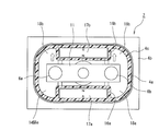
- magnet housing cylinder portions 16a and 16b are formed on the inner peripheral surface of the bowl-shaped body 4a facing the side surface orthogonal to the longitudinal direction of the movable contact 11, and these magnet housing cylinder portions 16a and 16a are formed.
- the arc extinguishing permanent magnets 17a and 17b are accommodated in 16b. These arc extinguishing permanent magnets 17a and 17b are magnetized such that the inner peripheral surfaces facing each other are N poles and the outer peripheral surfaces are magnetized S poles.
- the left and right spaces of the magnet housing cylinder portions 16a and 16b are arc extinguishing spaces 18a and 18b, respectively.
- a gas such as hydrogen gas, nitrogen gas, a mixed gas of hydrogen and nitrogen, air, SF 6 or the like is sealed in the arc extinguishing container 4 including the bowl-shaped body 4a, the joining member 4b, and the metal cylinder 4c.
- the electromagnet unit 3 has a U-shaped magnetic yoke 21 as viewed from the side, and a cylindrical portion 21 b having a lower end opened at the center of the bottom plate portion 21 a of the magnetic yoke 21.
- the upper surface side of the magnetic yoke 21 is connected by the upper magnetic yoke 22.
- a coil holder 24 around which an exciting coil 23 is wound is mounted on the outer peripheral surface of the cylindrical portion 21b of the magnetic yoke 21, and a bottomed cylindrical shape in which a movable iron core 25 is slidably mounted on the inner peripheral surface of the cylindrical portion 21b.
- a cap 26 is provided.
- a rubber seat 27 that contacts the bottom surface of the movable iron core 25 and absorbs an impact when the movable iron core 25 is lowered is disposed on the bottom surface of the cap 26.
- a connecting shaft 28 is fitted to the center of the movable iron core 25, and the head of the connecting shaft 28 extends upward through a through hole 29 formed in the upper magnetic yoke 22 and is connected to the contact holder 13. Yes. Further, a spring insertion hole 30 is formed around the connecting shaft 28 of the movable iron core 25, and a return spring 31 for biasing the movable iron core 25 downward is mounted between the spring insertion hole 30 and the upper magnetic yoke 22. Yes.
- the external connection terminal plate 15a is connected to a power supply source that supplies a large current, for example, and the external connection terminal plate 15b is connected to a load.
- the excitation coil 23 in the electromagnet unit 3 is in a non-energized state and no excitation force for moving the movable iron core 25 by the electromagnet unit 3 is generated.
- the movable iron core 25 is urged downward by the return spring 31 away from the upper magnetic yoke 22 and comes into contact with the rubber seat 27.
- the movable contact 11 supported by the contact holder 13 connected to the movable iron core 25 via the connecting shaft 28 sandwiches a predetermined gap from the lower end surface of the small diameter cylindrical portion 8 of the fixed contacts 6a and 6b.
- the contact device 2 is in an open (released) state.
- a closed state (input) state in which a large current i of the external power supply source is supplied to the load through the external connection terminal plate 15a, the fixed contact 6a, the movable contact 11, the fixed contact 6b, and the external connection terminal plate 15b. It becomes.
- the current supply to the load is cut off from the closed state of the contact device 2, the voltage application to the exciting coil 23 of the electromagnet unit 3 is stopped.
- the exciting force that moves the movable iron core 25 upward by the electromagnet unit 3 disappears, and the movable iron core 25 is lowered by the biasing force of the return spring 31.
- the contact holder 13 connected via the connecting shaft 28 is lowered.
- the movable contact 11 is in contact with the fixed contacts 6a and 6b while a contact pressure is applied by the contact spring 14 in accordance with the lowering of the contact holder 13. Thereafter, when the contact pressure of the contact spring 14 disappears, the movable contact 11 is brought into a contact opening start state in which the movable contact 11 is separated downward from the fixed contacts 6a and 6b.
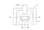
- the arc generating portion of the contact portion of the fixed contact 6b and the contact portion of the movable contact 11 traverses in the longitudinal direction of the movable contact 11 from the inside to the outside and reaches the S pole to form a magnetic field. Therefore, the magnetic fluxes of the arc extinguishing permanent magnets 17a and 17b are both opposite to each other in the longitudinal direction of the movable contact 11 between the fixed contact 6a and the movable contact 11 and between the fixed contact 6b and the movable contact 11. Will cross.
- This Lorentz force F causes an arc generated between the stationary contact 6a and the movable contact 11 to reach the lower surface side of the movable contact 11 from the side surface of the stationary contact 6a through the arc extinguishing space 18b. Is greatly stretched to extinguish the arc. Further, in the arc extinguishing space 18b, the direction of the magnetic flux between the fixed contact 6a and the movable contact 11 is uniform on the lower side and the upper side, and the current direction differs depending on the extension of the arc.
- the arc stretched in the arc extinguishing space 18b is stretched so that it further spreads in the direction of the corner of the arc extinguishing space 18b, the arc length can be lengthened, and good interrupting performance can be achieved. Obtainable.
- the arc generated between the fixed contact 6b and the movable contact 11 by this Lorentz force F reaches the side of the fixed contact 6b from the upper surface side of the movable contact 11 through the arc extinguishing space 18b.
- the direction of the magnetic flux between the fixed contact 6b and the movable contact 11 is uniform on the lower side and the upper side, and the direction of the current is caused by the extension of the arc. Different.
- the arc stretched in the arc extinguishing space 18b by the direction of the current is further stretched in the direction of the corner of the arc extinguishing space 18b, the arc length can be increased, and good interruption performance can be obtained. .
- the distance between the arc leg of the taper surface 12a or 12b of the movable contact 11 and the other leg of the arc formed on the fixed contacts 6a and 6b is increased, which is affected by metal vapor or the like. Without increasing the electric field strength. For this reason, it is possible to reliably prevent a re-occurring arc from occurring between the electrodes in the vicinity of the arc foot of the movable contact 11 and improve the interruption performance.
- the movable contact 11 is a flat surface on which the tapered surfaces 12a and 12b are not formed, an arc generated between the movable contact 11 and the fixed contacts 6a and 6b on the movable contact 11 side.
- the arc leg is stretched toward the arc extinguishing space 18b by the magnetic force of the arc extinguishing permanent magnets 17a and 17b, the arc leg remains at the corner between the flat surface and the side surface.
- the electric field strength between the arc legs may be lowered to an arc voltage or less due to metal vapor or the like.
- a recurring arc is generated between the electrodes in the vicinity of the arc foot, and the interruption performance is reduced.
- the arc foot can easily move to the surface of the movable contact 11 opposite to the fixed contacts 6a and 6b and can easily extend. Therefore, the blocking performance can be further improved.
- the arc foot movement promoting portion 12 including the tapered surfaces 12a and 12b is formed on the side surface orthogonal to the longitudinal direction of the movable contact 11, the movable contact 11 is fixed. It is possible to easily move the foot on the movable contact side of the arc generated at the time of opening apart from the contacts 6a and 6b along the tapered surface 12a (or 12b).
- the distance between the arc legs generated between the movable contact 11 and the fixed contacts 6a and 6b is increased to increase the electric field strength, thereby preventing re-arcing and quickening the arc extinction to improve the interruption performance. be able to.
- the gap between the fixed contacts 6a and 6b and the movable contact 11 can be narrowed, and the opening time for cutting off the current can be shortened. it can.
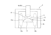
- the portion of the fixed contacts 6a and 6b facing the movable contact 11 is the small-diameter cylindrical portion 8.
- the present invention is not limited to this.
- the contact portions of the fixed contacts 6a and 6b facing the movable contact 11 may be formed on the curved surface 41 having a spherical or cylindrical shape.
- the legs of the arc also move upward on the fixed contacts 6a and 6b side, the distance between the arc legs can be made longer, and the arc is extinguished more reliably and the interruption performance. Can be further improved.
- the arc leg movement promotion part 12 was formed in taper surface 12a, 12b was demonstrated, it is not limited to this, As shown in FIG.
- the arcuate curved surfaces 42a and 42b that form a part of the curved surface may be used. In this case, as the arc foot moves outward along the arcuate curved surfaces 42a and 42b, the distance between the stationary contact 6a and 6b and the arc foot can be increased, and the interruption performance is further improved. Can be made.
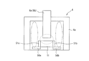
- an arc runner is provided as an arc foot movement promoting portion instead of the inclined surface. That is, in the second embodiment, as shown in FIG. 7, an arc runner 51 a that covers the side surface in a direction orthogonal to the longitudinal direction of the movable contact 11 having a rectangular cross section and extends downward from the lower surface of the movable contact 11, 52b is fixed.
- each of the arc runners 51a and 51b may be formed of an arc-resistant material such as tungsten (W) or silver (Ag), or a metal material having conductivity such as copper (Cu).
- the arc leg on the movable contactor 11 side moves to the side of the arc runner 51a (or 51b) as the arc leg is extended to the arc extinguishing space 18a (or 18b) side, and the arc leg moves to the arc runner.
- 51a (or 51b) it will rapidly move downward along this arc runner 51a (or 51b).
- the legs of the arc do not stay at the corners of the side surface of the movable contact 11, and the distance between the fixed contacts 6a and 6b and the legs of the arc is lengthened to prevent the electric field strength from being lowered due to metal vapor or the like. be able to. Therefore, the arc can be easily extinguished and the interruption performance can be improved.
- the present invention is not limited to this, and both arc runners 51a and 51b are used.
- the upper end portions may be connected by a connecting portion 51c to form an inverted U-shaped cross section.
- a groove 52 extending in the front-rear direction is formed on the surface of the movable contact 11 facing the fixed contacts 6a and 6b, and the connecting portion 51c is engaged with and fixed to the groove 52.
- an arc runner 53 formed in an inverted U shape may be fixed to the lower surface side of the movable contact 11. Even in this case, when the arc is stretched by the arc extinguishing permanent magnets 17a and 17b and reaches the end portion on the side surface side of the movable contact 11, the arc foot does not stay at the end portion, but on the lower surface side. It is drawn to the formed arc runner 53. For this reason, the distance between the arc leg on the movable contact 11 side and the arc leg of the fixed contacts 6a and 6b can be lengthened, and the electric field strength between the arc legs can be increased to improve the interruption performance.
- the arc runners 54a and 54b on the lower surface side of the movable contactor 11 may be bent inward and inclined inward.
- the arc foot of the movable contact 11 can be moved to the lower surface side of the movable contact 11, and the lower side of the movable contact 11 can be used as an arc extinguishing space.
- the stretched length can be increased to facilitate arc extinction, and the volume can be effectively used.
- the arc runners 55a and 55b on the lower side of the movable contactor 11 may be bent outward and inclined outward as opposed to FIG. In this case, the arc foot can be moved in the direction in which the arc is easily spread on the lower surface side of the movable contact 11. The arc foot can be moved reliably and the arc can be easily extinguished.
- the arc runners 56a and 56b on the lower side of the movable contactor 11 may be bent outward in a right angle direction and protrude outward. Also in this case, similarly to FIG. 11, the arc foot can be moved in the direction in which the arc easily spreads on the lower surface side of the movable contact 11, and the arc foot can be reliably moved to easily extinguish the arc. be able to.
- the surfaces of the fixed contacts 6a and 6b facing the movable contact 11 are formed in a spherical shape or a cylindrical surface shape. Also good.
- the arc extinguishing permanent magnets 17a and 17b are arranged inside the rod-shaped body 4a.
- the arc permanent magnets 17a and 17b may be arranged outside the bowl-shaped body 4a in parallel with the movable contactor 11.
- the said 1st and 2nd embodiment demonstrated the case where the arc-extinguishing container 4 was comprised by the rod-shaped body 4a, the joining member 4b, and the metal cylinder 4c, it is not limited to this, A metal An insulating cylinder may be arranged inside the made cage, and any configuration can be adopted.
- the case where gas is sealed in the arc extinguishing container 4 has been described.
- the present invention is not limited to this, and when the current value to be cut off is small, the gas is sealed. Can be omitted.
- the movable contact 11 may be formed in flat form in the longitudinal direction, it is not limited to this,
- the movable contact 11 The central part between the contact parts facing the fixed contacts 6a, 6b may be formed in a concave or convex shape.
- the fixed contact 6a And 6b may be arranged on the lower side of the arc extinguishing container 4, and the movable contact 11 may be opposed to the contact parts from the upper side.
- the configuration of the electromagnet unit 3 is not limited to the above embodiment, and any configuration can be applied as long as the contact holder 13 can be moved by electromagnetic force. Furthermore, in the said embodiment, although the case where the contact apparatus 2 of this invention was applied to an electromagnetic contactor was demonstrated, it is not limited to this, Arbitrary switches including an electromagnetic relay and another electromagnetic switch Can be applied to.
- the arc foot movement promoting part is formed that moves the foot of the arc generated when the movable contact is opened in a direction away from the fixed contact. Therefore, it is possible to provide a contact device that can easily extinguish an arc generated between the fixed contact and the movable contact at the time of opening, and an electromagnetic switch using the contact device.
Abstract
Provided are a contact device and an electromagnetic switch using said contact device that are capable of easily extinguishing an arc generated between a fixed contact element and a movable contact element when said contact device is open. Said contact device is provided with: a pair of fixed contact elements (6a, 6b) that, maintaining a specified interval, are fixed in place in an arc-extinguishing chamber; and the movable contact element (11), which is arranged so as to enable attachment to/removal from the pair of fixed contact elements. An arc root movement promotion section (12) is formed on the movable contact element (11), said arc root movement promotion section (12) promoting movement of the root of the arc generated when the contact device is open, at which the movable contact element separates from the pair of fixed contact elements.
Description
本発明は、電流路に介挿された固定接触子及び可動接触子を備えた接点装置及びこれを使用した電磁開閉器に関し、固定接触子及び可動接触子の開極時すなわち電流遮断時に発生するアークを容易に消弧するようにしたものである。
The present invention relates to a contact device including a stationary contact and a movable contact inserted in a current path and an electromagnetic switch using the contact device, and occurs when the stationary contact and the movable contact are opened, that is, when a current is interrupted. The arc is extinguished easily.
電流路の開閉を行う接点装置として、従来、電磁継電器や電磁接触器などでは、固定接触子及び可動接触子が接触している接点機構の閉成状態から電流を遮断して開成状態とするために可動接触子を固定接触子から離間させる開極時に発生するアークを消弧する接点機構が種々提案されている。
例えば、所定距離だけ離間して配設されたそれぞれ固定接点を有する一対の固定接触子と、これら一対の固定接触子に接離自在に配設された左右端に可動接点を有する可動接触子と、可動接触子を駆動する電磁石装置と、可動接触子及び固定接触子を収納する囲み部材とを備え、囲み部材の外側に可動接触子と平行にアーク消弧用の永久磁石を配置した電磁開閉装置が提案されている(例えば、特許文献1参照)。 Conventionally, as a contact device that opens and closes a current path, in an electromagnetic relay, an electromagnetic contactor, etc., the current is cut off from the closed state of the contact mechanism in contact with the fixed contact and the movable contact to be opened. Various contact mechanisms have been proposed for extinguishing an arc generated during opening of a pole that separates the movable contact from the fixed contact.
For example, a pair of fixed contacts each having a fixed contact disposed at a predetermined distance away from each other, and a movable contact having a movable contact at left and right ends disposed so as to be able to contact with and separate from the pair of fixed contacts An electromagnetic switching device comprising an electromagnet device for driving the movable contact and an enclosing member for housing the movable contact and the stationary contact, and an arc extinguishing permanent magnet arranged in parallel to the moveable contact on the outside of the enclosing member An apparatus has been proposed (see, for example, Patent Document 1).
しかしながら、上記特許文献1に記載された従来例にあっては、永久磁石の磁力によってアークを引き伸ばして消弧し易くなるものの、固定接触子に可動接触子が接触している投入状態から可動接触子を離間させる電流遮断時すなわち開極時に発生するアークの足は、永久磁石の磁力によって可動接触子の可動接点を消弧空間側へ移動する。移動したアークの足は可動接触子の角部に留まってアーク足から生じる金属蒸気等により電界強度低下が生じ、アークの再発弧が繰り返されるなど遮断性能が低下するという未解決の課題がある。
そこで、本発明は、上記従来例の未解決の課題に着目してなされたものであり、開極時に固定接触子及び可動接触子間に発生するアークを容易に消弧することができる接点装置及びこれを使用した電磁開閉器を提供することを目的としている。 However, in the conventional example described in Patent Document 1, it is easy to extinguish the arc by stretching the arc by the magnetic force of the permanent magnet, but it is possible to move the movable contact from the input state in which the movable contact is in contact with the fixed contact. The legs of the arc generated at the time of interrupting the current that separates the child, that is, at the time of opening, move the movable contact of the movable contact to the arc extinguishing space side by the magnetic force of the permanent magnet. There is an unsolved problem that the electric field strength is lowered due to the metal vapor generated from the arc foot while the foot of the moving arc stays at the corner of the movable contact, and the interruption performance is lowered, for example, the arc is repeatedly re-ignited.
Accordingly, the present invention has been made paying attention to the unsolved problems of the above-described conventional example, and a contact device that can easily extinguish an arc generated between a fixed contact and a movable contact at the time of opening. And it aims at providing the electromagnetic switch using this.
上記目的を達成するために、本発明に係る接点装置の第1の態様は、消弧室内に所定間隔を保って固定配置された一対の固定接触子と、該一対の固定接触子に対して接離可能に配設された可動接触子とを備えている。そして、前記可動接触子には、前記一対の固定接触子から離間する開極時に発生するアークの足の当該固定接触子から離れる方向への移動を促進するアーク足移動促進部を形成している。
In order to achieve the above object, a first aspect of the contact device according to the present invention includes a pair of fixed contacts fixedly arranged in the arc extinguishing chamber at a predetermined interval, and the pair of fixed contacts. And a movable contact arranged so as to be able to contact and separate. The movable contact is provided with an arc foot movement promoting portion that promotes movement of an arc foot generated at the time of opening away from the pair of fixed contacts in a direction away from the fixed contact. .
この第1の態様によると、可動接触子が一対の固定接触子から離間する開極時に、可動接触子と一対の固定接触子との間にアークが発生する。このとき、可動接触子にアーク足移動促進部が形成されているので、このアーク足移動促進部によって発生したアークの足が角部に留まることなく固定接触子から離れる方向へ移動させることができる。したがって、アーク発生時の電界強度が大きくなり、アークの再発弧を抑制して遮断性能を向上させることができる。
According to the first aspect, an arc is generated between the movable contact and the pair of fixed contacts when the movable contact is separated from the pair of fixed contacts. At this time, since the arc foot movement promoting portion is formed on the movable contact, the arc foot generated by the arc foot movement promoting portion can be moved away from the fixed contact without staying at the corner. . Therefore, the electric field strength at the time of arc generation becomes large, and it is possible to suppress the recurrence of the arc and improve the interruption performance.
また、本発明に係る接点装置の第2の態様は、前記アーク足移動促進部が、前記可動接触子の電流の通流方向と直交する方向で端部に行くに従い厚みが薄くなる傾斜面で構成されている。
この第2の態様によると、可動接触子の電流の通流方向と直交する方向で段部に行くに従い厚みが薄くなるテーパー面、円弧面等の傾斜面が形成されているので、この傾斜面に沿ってアークの足の下方への移動が促進される。 In addition, a second aspect of the contact device according to the present invention is an inclined surface in which the arc foot movement promoting portion becomes thinner as it goes to the end portion in a direction perpendicular to the current flow direction of the movable contact. It is configured.
According to the second aspect, since the inclined surface such as the tapered surface or the arc surface whose thickness decreases as it goes to the step portion in the direction orthogonal to the current flow direction of the movable contact, the inclined surface is formed. The downward movement of the arc foot is promoted.
また、本発明に係る接点装置の第3の態様は、前記傾斜面が、テーパー面で構成されている。
この第3の態様によると、傾斜面がテーパー面であるので、アーク足移動促進部を有する可動接触子を容易に形成することができる。
また、本発明に係る接点装置の第4の態様は、前記傾斜面が、円弧状湾曲面で構成されている。
この第4の態様によると、傾斜面が円弧状湾曲面であるので、可動接触子の底面側に達するまでの間に角部が生じることがなく、アークの足の移動を容易かつ確実に行うことができる。 Moreover, as for the 3rd aspect of the contact device which concerns on this invention, the said inclined surface is comprised by the taper surface.
According to the third aspect, since the inclined surface is a tapered surface, it is possible to easily form the movable contact having the arc foot movement promoting portion.
In a fourth aspect of the contact device according to the present invention, the inclined surface is formed by an arcuate curved surface.
According to the fourth aspect, since the inclined surface is an arcuate curved surface, no corner is formed before the movable contactor reaches the bottom surface side, and the arc foot is easily and reliably moved. be able to.
また、本発明に係る接点装置の第5の態様は、前記アーク足移動促進部が、前記可動接触子の電流通流方向と直交する端面に形成した前記一対の固定接触子側とは反対側に突出延長するアークランナーで構成されている。
この第5の態様によると、アーク足移動促進部としてアークランナーを設け、このアークランナーを可動接触子の一対の固定接触子とは反対側に突出延長させている。このため、開極時に発生するアークの足が角部に留まることなく固定接触子から離れる方向に移動されるのでアーク発生時の電界強度を大きくして再発弧を抑制し、遮断性能を向上させることができる。 Moreover, the 5th aspect of the contact apparatus which concerns on this invention is an opposite side to the said pair of stationary contact side which the said arc leg movement promotion part formed in the end surface orthogonal to the electric current flow direction of the said movable contact. It consists of an arc runner that protrudes and extends.
According to this 5th aspect, an arc runner is provided as an arc leg movement promotion part, and this arc runner is projected and extended on the opposite side to a pair of fixed contacts of a movable contact. For this reason, since the legs of the arc generated at the time of opening are moved in the direction away from the fixed contact without staying at the corners, the electric field strength at the time of arc generation is increased to suppress recurring arcs and improve the breaking performance be able to.
また、本発明に係る接点装置の第6の形態は、前記アークランナーが、前記可動接触子の側面を覆うように形成されている。
この第6の態様によると、開極時に発生したアークの足が可動接触子の角部に達したときに、アークランナーを伝って下方に確実に移動されることになり、遮断性能を向上させることかできる。 Moreover, the 6th form of the contact apparatus which concerns on this invention is formed so that the said arc runner may cover the side surface of the said movable contact.
According to the sixth aspect, when the leg of the arc generated at the time of opening reaches the corner of the movable contact, it is surely moved downward along the arc runner, thereby improving the breaking performance. I can do it.
また、本発明に係る接点装置の第7の態様は、前記アークランナーが、前記可動接触子の前記一対の固定接触子とは反対側の突出部が内方に傾斜されている。
この第7の態様は、アークランナーの可動接触子における固定接触子とは反対側で内方に傾斜しているので、アークの足を可動接触子の下側に拡げることができ、アーク消弧スペースを拡大して容積の有効利用を行うことができる。 Further, according to a seventh aspect of the contact device of the present invention, the arc runner has an inwardly inclined protrusion on the side of the movable contact opposite to the pair of fixed contacts.
In the seventh aspect, since the movable contact of the arc runner is inclined inward on the side opposite to the fixed contact, the arc foot can be extended to the lower side of the movable contact, and the arc extinguishing can be performed. The space can be expanded and the volume can be used effectively.
また、本発明に係る接点装置の第8の態様は、前記アークランナーが、前記可動接触子の前記一対の固定接触子とは反対側の突出部が外方に傾斜されている。
この第8の態様によると、アークランナーが可動接触子の下側で外方に傾斜されているので、アークの足を広がり易い方向へ延ばして、固定接触子のアーク足との距離を広げることができる。 According to an eighth aspect of the contact device of the present invention, the arc runner is configured such that a protruding portion of the movable contact opposite to the pair of fixed contacts is inclined outward.
According to the eighth aspect, since the arc runner is inclined outward on the lower side of the movable contact, the distance between the arc foot of the fixed contact is increased by extending the arc foot in a direction that is easy to spread. Can do.
また、本発明に係る接点装置の第9の態様は、前記アークランナーは、前記可動接触子の前記一対の固定接触子とは反対側の突出部が外方に突出延長されている。
この第9の態様によると、アークランナーによってアークの足を外側に広げて固定接触子のアーク足との距離を広げることができる。 In the ninth aspect of the contact device according to the present invention, the arc runner has a protruding portion of the movable contact opposite to the pair of fixed contacts that extends outwardly.
According to the ninth aspect, the arc runner can widen the arc leg outward and the distance between the fixed contact and the arc leg can be increased.
また、本発明に係る電磁開閉器の第1の態様は、上記第1~第9の態様の接点装置を備え、前記可動接触子が電磁石装置の可動鉄心に連結され、前記固定接触子が外部接続端子に接続されている。
この構成によると、簡単な構成で開極時に発生するアークを確実に消弧して遮断性能を向上することができる電磁開閉器を提供することができる。 A first aspect of the electromagnetic switch according to the present invention includes the contact device according to the first to ninth aspects, wherein the movable contact is connected to a movable iron core of an electromagnet device, and the fixed contact is externally provided. Connected to the connection terminal.
According to this configuration, it is possible to provide an electromagnetic switch capable of improving the interrupting performance by reliably extinguishing an arc generated at the time of opening with a simple configuration.
本発明によれば、可動接触子に開極時に発生するアークの足を固定接触子から離れる方向に移動させるアーク足移動促進部を形成したので、開極時に発生したアークが可動接触子の角部に留まってアーク足間の電界強度がアーク電圧以下に低下してアーク足近傍の電極間に再点弧が発生することを確実に防止して遮断性能を向上させることができる。
また、上記効果を有する接点装置を電磁開閉器に適用することにより、簡易な構成で開極時に発生するアークを容易に消弧して遮断性能を向上することができる電磁接触器、電磁継電器等の電磁開閉器を提供することができる。 According to the present invention, since the arc foot movement accelerating portion that moves the foot of the arc generated at the opening of the movable contact in the direction away from the fixed contact is formed, the arc generated at the time of opening the angle of the movable contact The electric field strength between the arc feet stays at the portion and falls below the arc voltage, so that reignition between the electrodes in the vicinity of the arc feet is surely prevented and the interruption performance can be improved.
In addition, by applying the contact device having the above effects to an electromagnetic switch, an electromagnetic contactor, an electromagnetic relay, etc. that can easily extinguish an arc generated at the time of opening with a simple configuration and improve a breaking performance. An electromagnetic switch can be provided.
以下、本発明の実施の形態を図面に基づいて説明する。
図1は本発明の接点装置を電磁開閉器としての電磁接触器に適用した場合の一例を示す断面図である。この図1において、1は例えば合成樹脂製の外装ケースである。この外装ケース1は、下端面が開放された有底筒体1aと、この有底筒体1aの下端面を閉塞する底板1bとで構成されている。
外装ケース1内には、接点機構を配置した接点装置2と、この接点装置2を駆動する電磁石装置としての電磁石ユニット3とが電磁石ユニット3を底板1b上に配置した関係で収納されている。 Hereinafter, embodiments of the present invention will be described with reference to the drawings.
FIG. 1 is a sectional view showing an example in which the contact device of the present invention is applied to an electromagnetic contactor as an electromagnetic switch. In FIG. 1, 1 is an exterior case made of, for example, a synthetic resin. The exterior case 1 includes a bottomedcylindrical body 1a whose lower end surface is opened and a bottom plate 1b that closes the lower end surface of the bottomed cylindrical body 1a.
In the exterior case 1, acontact device 2 having a contact mechanism and an electromagnet unit 3 as an electromagnet device for driving the contact device 2 are accommodated in a relationship in which the electromagnet unit 3 is arranged on the bottom plate 1b.
図1は本発明の接点装置を電磁開閉器としての電磁接触器に適用した場合の一例を示す断面図である。この図1において、1は例えば合成樹脂製の外装ケースである。この外装ケース1は、下端面が開放された有底筒体1aと、この有底筒体1aの下端面を閉塞する底板1bとで構成されている。
外装ケース1内には、接点機構を配置した接点装置2と、この接点装置2を駆動する電磁石装置としての電磁石ユニット3とが電磁石ユニット3を底板1b上に配置した関係で収納されている。 Hereinafter, embodiments of the present invention will be described with reference to the drawings.
FIG. 1 is a sectional view showing an example in which the contact device of the present invention is applied to an electromagnetic contactor as an electromagnetic switch. In FIG. 1, 1 is an exterior case made of, for example, a synthetic resin. The exterior case 1 includes a bottomed
In the exterior case 1, a
接点装置2は、図2及び図3とともに参照して明らかなように、消弧容器4を有する、この消弧容器4は、セラミックス、合成樹脂等で形成される下端を開放した桶状体4aとその開放端面に密着固定された金属製の接合部材4b、桶状体4aの側面を覆う金属筒体4cとで構成されている。そして、接合部材4bが電磁石ユニット3の上部磁気ヨーク22の上面にろう付け、溶接等によって気密状態で固定されている。
2 and 3, the contact device 2 has an arc extinguishing container 4. The arc extinguishing container 4 is a bowl-shaped body 4a having a lower end formed of ceramics, synthetic resin or the like. And a metal joining member 4b that is tightly fixed to the open end surface thereof, and a metal cylinder 4c that covers the side surface of the bowl-shaped body 4a. The joining member 4b is fixed to the upper surface of the upper magnetic yoke 22 of the electromagnet unit 3 in an airtight state by brazing, welding, or the like.
桶状体4aの上面には、長手方向に所定間隔を保って断面円形の貫通孔5a,5bが設けられ、これら貫通孔5a,5b内に例えば銅製の一対の固定接触子6a,6bが挿通されてろう付けや接着剤等によって固定されている。
この固定接触子6a,6bのそれぞれは、上部側の大径頭部7とこの大径頭部7と同軸的に連接された下部側の小径円柱部8とで構成されている。
これら固定接触子6a,6bが小径円柱部8を桶状体4aの貫通孔5a,5b内に挿通した状態で桶状体4aにろう付けや接着剤等によって貫通孔5a,5bを密封するように固定されている。 On the upper surface of the bowl-shapedbody 4a, through holes 5a and 5b having a circular cross section are provided in the longitudinal direction at a predetermined interval, and a pair of, for example, copper fixed contacts 6a and 6b are inserted into the through holes 5a and 5b. It is fixed by brazing or adhesive.
Each of the fixed contacts 6 a and 6 b is composed of an upper-side large-diameter head 7 and a lower-side small-diameter cylindrical portion 8 that is coaxially connected to the large-diameter head 7.
These fixed contacts 6a, 6b seal the through holes 5a, 5b by brazing, adhesive, or the like to the rod-like body 4a in a state where the small-diameter cylindrical portion 8 is inserted into the through-holes 5a, 5b of the rod-like body 4a. It is fixed to.
この固定接触子6a,6bのそれぞれは、上部側の大径頭部7とこの大径頭部7と同軸的に連接された下部側の小径円柱部8とで構成されている。
これら固定接触子6a,6bが小径円柱部8を桶状体4aの貫通孔5a,5b内に挿通した状態で桶状体4aにろう付けや接着剤等によって貫通孔5a,5bを密封するように固定されている。 On the upper surface of the bowl-shaped
Each of the fixed
These fixed
また、接点装置2は、固定接触子6a,6bの小径円柱部8の下端面に比較的狭い所定のギャップを隔てて可動接触子11が接離可能に対向配置されている。この可動接触子11は、図2に示すように、少なくとも固定接触子6a,6bと対向する位置に平坦面11aが形成されている。また、可動接触子11には、平坦面11aの可動接触子11の長手方向と直交する方向すなわち前後端部側にアーク足移動促進部12が形成されている。このアーク足移動促進部12は、平坦面11aの前後端部から可動接触子11の前後端部に向かって厚みが徐々に薄くなる傾斜面すなわちテーパー面12a,12bで構成されている。
In the contact device 2, the movable contact 11 is opposed to the lower end surfaces of the small-diameter cylindrical portions 8 of the fixed contacts 6a and 6b so that the movable contact 11 can be contacted and separated with a relatively narrow predetermined gap. As shown in FIG. 2, the movable contact 11 has a flat surface 11a formed at least at a position facing the fixed contacts 6a and 6b. The movable contact 11 is formed with an arc foot movement promoting portion 12 in a direction orthogonal to the longitudinal direction of the movable contact 11 on the flat surface 11a, that is, on the front and rear end side. The arc foot movement promoting portion 12 is composed of inclined surfaces, that is, tapered surfaces 12 a and 12 b, whose thickness gradually decreases from the front and rear end portions of the flat surface 11 a toward the front and rear end portions of the movable contact 11.
そして、可動接触子11は接触子ホルダ13に接触スプリング14によって上方に付勢されて装着されている。接触子ホルダ13は、後述する電磁石ユニット3の可動鉄心25に連結されて上下方向に駆動される。
さらに、固定接触子6a,6bの大径頭部7には外部接続端子板15a,15bがビス止めされている。
また、桶状体4aの可動接触子11の長手方向と直交する側面に対向する内周面に図3に示すように、磁石収納筒部16a及び16bが形成され、これら磁石収納筒部16a及び16b内にアーク消弧用永久磁石17a及び17bが収納されている。これらアーク消弧用永久磁石17a及び17bは、互いに対向する内周面側がN極に、外周面側がS極に着磁されている。 Themovable contact 11 is attached to the contact holder 13 by being urged upward by a contact spring 14. The contact holder 13 is connected to a movable iron core 25 of the electromagnet unit 3 described later and is driven in the vertical direction.
Further, external connection terminal plates 15a and 15b are screwed to the large-diameter heads 7 of the fixed contacts 6a and 6b.
Further, as shown in FIG. 3, magnet housing cylinder portions 16a and 16b are formed on the inner peripheral surface of the bowl-shaped body 4a facing the side surface orthogonal to the longitudinal direction of the movable contact 11, and these magnet housing cylinder portions 16a and 16a are formed. The arc extinguishing permanent magnets 17a and 17b are accommodated in 16b. These arc extinguishing permanent magnets 17a and 17b are magnetized such that the inner peripheral surfaces facing each other are N poles and the outer peripheral surfaces are magnetized S poles.
さらに、固定接触子6a,6bの大径頭部7には外部接続端子板15a,15bがビス止めされている。
また、桶状体4aの可動接触子11の長手方向と直交する側面に対向する内周面に図3に示すように、磁石収納筒部16a及び16bが形成され、これら磁石収納筒部16a及び16b内にアーク消弧用永久磁石17a及び17bが収納されている。これらアーク消弧用永久磁石17a及び17bは、互いに対向する内周面側がN極に、外周面側がS極に着磁されている。 The
Further, external
Further, as shown in FIG. 3, magnet
そして、磁石収納筒部16a及び16bの左右の空間がそれぞれアーク消弧空間18a及び18bとされている。
そして、桶状体4a、接合部材4b及び金属筒体4cで構成される消弧容器4内に水素ガス、窒素ガス、水素及び窒素の混合ガス、空気、SF6等のガスが封入されている。
電磁石ユニット3は、側面から見てU字形状の磁気ヨーク21を有し、この磁気ヨーク21の底板部21aの中央部に下端を開放した円筒部21bが形成されている。この磁気ヨーク21の上面側が上部磁気ヨーク22によって連接されている。 The left and right spaces of the magnet housing cylinder portions 16a and 16b are arc extinguishing spaces 18a and 18b, respectively.
A gas such as hydrogen gas, nitrogen gas, a mixed gas of hydrogen and nitrogen, air, SF 6 or the like is sealed in thearc extinguishing container 4 including the bowl-shaped body 4a, the joining member 4b, and the metal cylinder 4c. .
Theelectromagnet unit 3 has a U-shaped magnetic yoke 21 as viewed from the side, and a cylindrical portion 21 b having a lower end opened at the center of the bottom plate portion 21 a of the magnetic yoke 21. The upper surface side of the magnetic yoke 21 is connected by the upper magnetic yoke 22.
そして、桶状体4a、接合部材4b及び金属筒体4cで構成される消弧容器4内に水素ガス、窒素ガス、水素及び窒素の混合ガス、空気、SF6等のガスが封入されている。
電磁石ユニット3は、側面から見てU字形状の磁気ヨーク21を有し、この磁気ヨーク21の底板部21aの中央部に下端を開放した円筒部21bが形成されている。この磁気ヨーク21の上面側が上部磁気ヨーク22によって連接されている。 The left and right spaces of the magnet
A gas such as hydrogen gas, nitrogen gas, a mixed gas of hydrogen and nitrogen, air, SF 6 or the like is sealed in the
The
磁気ヨーク21の円筒部21bの外周面には励磁コイル23を巻装したコイルホルダ24が装着され、円筒部21bの内周面には可動鉄心25を摺動可能に内装した有底円筒状のキャップ26が配設されている。このキャップ26の底面には、可動鉄心25の底面と接触して可動鉄心25の下降時の衝撃を吸収するゴム座27が配設されている。
A coil holder 24 around which an exciting coil 23 is wound is mounted on the outer peripheral surface of the cylindrical portion 21b of the magnetic yoke 21, and a bottomed cylindrical shape in which a movable iron core 25 is slidably mounted on the inner peripheral surface of the cylindrical portion 21b. A cap 26 is provided. A rubber seat 27 that contacts the bottom surface of the movable iron core 25 and absorbs an impact when the movable iron core 25 is lowered is disposed on the bottom surface of the cap 26.
可動鉄心25には、中心部に連結軸28が嵌合され、この連結軸28の頭部が上部磁気ヨーク22に形成された貫通孔29を通じて上方に延長され、接触子ホルダ13に連結されている。
また、可動鉄心25の連結軸28の周囲にスプリング挿通孔30が形成され、このスプリング挿通孔30と上部磁気ヨーク22との間に可動鉄心25を下方に付勢する復帰スプリング31が装着されている。 A connectingshaft 28 is fitted to the center of the movable iron core 25, and the head of the connecting shaft 28 extends upward through a through hole 29 formed in the upper magnetic yoke 22 and is connected to the contact holder 13. Yes.
Further, aspring insertion hole 30 is formed around the connecting shaft 28 of the movable iron core 25, and a return spring 31 for biasing the movable iron core 25 downward is mounted between the spring insertion hole 30 and the upper magnetic yoke 22. Yes.
また、可動鉄心25の連結軸28の周囲にスプリング挿通孔30が形成され、このスプリング挿通孔30と上部磁気ヨーク22との間に可動鉄心25を下方に付勢する復帰スプリング31が装着されている。 A connecting
Further, a
次に、上記実施形態の動作を説明する。
今、外部接続端子板15aが例えば大電流を供給する電力供給源に接続され、外部接続端子板15bが負荷に接続されているものとする。
この状態で、電磁石ユニット3における励磁コイル23が非通電状態にあって、電磁石ユニット3で可動鉄心25を可動させる励磁力を発生していないものとする。この状態では、可動鉄心25が復帰スプリング31によって、上部磁気ヨーク22から離れる下方向に付勢されて、ゴム座27に当接した状態となる。このため、可動鉄心25に連結軸28を介して連結された接触子ホルダ13に支持された可動接触子11は、固定接触子6a,6bの小径円柱部8の下端面から所定のギャップを挟んで対向しており、接点装置2が開極(釈放)状態となっている。 Next, the operation of the above embodiment will be described.
Now, it is assumed that the externalconnection terminal plate 15a is connected to a power supply source that supplies a large current, for example, and the external connection terminal plate 15b is connected to a load.
In this state, it is assumed that theexcitation coil 23 in the electromagnet unit 3 is in a non-energized state and no excitation force for moving the movable iron core 25 by the electromagnet unit 3 is generated. In this state, the movable iron core 25 is urged downward by the return spring 31 away from the upper magnetic yoke 22 and comes into contact with the rubber seat 27. For this reason, the movable contact 11 supported by the contact holder 13 connected to the movable iron core 25 via the connecting shaft 28 sandwiches a predetermined gap from the lower end surface of the small diameter cylindrical portion 8 of the fixed contacts 6a and 6b. The contact device 2 is in an open (released) state.
今、外部接続端子板15aが例えば大電流を供給する電力供給源に接続され、外部接続端子板15bが負荷に接続されているものとする。
この状態で、電磁石ユニット3における励磁コイル23が非通電状態にあって、電磁石ユニット3で可動鉄心25を可動させる励磁力を発生していないものとする。この状態では、可動鉄心25が復帰スプリング31によって、上部磁気ヨーク22から離れる下方向に付勢されて、ゴム座27に当接した状態となる。このため、可動鉄心25に連結軸28を介して連結された接触子ホルダ13に支持された可動接触子11は、固定接触子6a,6bの小径円柱部8の下端面から所定のギャップを挟んで対向しており、接点装置2が開極(釈放)状態となっている。 Next, the operation of the above embodiment will be described.
Now, it is assumed that the external
In this state, it is assumed that the
この接点装置2の開極状態から、電磁石ユニット3の励磁コイル23に通電すると、この電磁石ユニット3で励磁力を発生させて、可動鉄心25を復帰スプリング31に抗して上方に押し上げる。これに応じて、可動鉄心25に連結軸28を介して連結されている接触子ホルダ13が上方に移動し、可動接触子11が固定接触子6a,6bの小径円柱部8の底面に接触スプリング14の接触圧で接触する。
When the exciting coil 23 of the electromagnet unit 3 is energized from the open state of the contact device 2, an exciting force is generated by the electromagnet unit 3 to push the movable iron core 25 upward against the return spring 31. In response to this, the contact holder 13 connected to the movable iron core 25 via the connecting shaft 28 moves upward, and the movable contact 11 contacts the bottom surface of the small-diameter cylindrical portion 8 of the fixed contacts 6a and 6b. Contact with a contact pressure of 14.
このため、外部電力供給源の大電流iが外部接続端子板15a、固定接触子6a、可動接触子11、固定接触子6b及び外部接続端子板15bを通じて負荷に供給される閉極(投入)状態となる。
この接点装置2の閉極状態から、負荷への電流供給を遮断する場合には、電磁石ユニット3の励磁コイル23への電圧印加を停止する。 For this reason, a closed state (input) state in which a large current i of the external power supply source is supplied to the load through the externalconnection terminal plate 15a, the fixed contact 6a, the movable contact 11, the fixed contact 6b, and the external connection terminal plate 15b. It becomes.
When the current supply to the load is cut off from the closed state of thecontact device 2, the voltage application to the exciting coil 23 of the electromagnet unit 3 is stopped.
この接点装置2の閉極状態から、負荷への電流供給を遮断する場合には、電磁石ユニット3の励磁コイル23への電圧印加を停止する。 For this reason, a closed state (input) state in which a large current i of the external power supply source is supplied to the load through the external
When the current supply to the load is cut off from the closed state of the
これによって、電磁石ユニット3で可動鉄心25を上方に移動させる励磁力がなくなることにより、可動鉄心25が復帰スプリング31の付勢力によって下降する。この可動鉄心25が下降することにより、連結軸28を介して連結された接触子ホルダ13が下降する。この接触子ホルダ13の下降に応じて接触スプリング14で接触圧を与えている間は可動接触子11が固定接触子6a,6bに接触している。その後、接触スプリング14の接触圧がなくなった時点で可動接触子11が固定接触子6a,6bから下方に離間する開極開始状態となる。
Thereby, the exciting force that moves the movable iron core 25 upward by the electromagnet unit 3 disappears, and the movable iron core 25 is lowered by the biasing force of the return spring 31. When the movable iron core 25 is lowered, the contact holder 13 connected via the connecting shaft 28 is lowered. The movable contact 11 is in contact with the fixed contacts 6a and 6b while a contact pressure is applied by the contact spring 14 in accordance with the lowering of the contact holder 13. Thereafter, when the contact pressure of the contact spring 14 disappears, the movable contact 11 is brought into a contact opening start state in which the movable contact 11 is separated downward from the fixed contacts 6a and 6b.
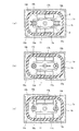
この開極開始状態となると、固定接触子6a,6bと可動接触子11との間にアークが発生する。このとき、アーク消弧用永久磁石17a及び17bの対向磁極面がN極であり、その外側がS極である。このため、N極が出た磁束が、平面から見て図4(a)に示すように、各アーク消弧用永久磁石17a及び17b、固定接触子6aと可動接触子11との対向部のアーク発生部を可動接触子11の長手方向に内側から外側に横切ってS極に達して磁界が形成される。
In this opening start state, an arc is generated between the fixed contacts 6a and 6b and the movable contact 11. At this time, the opposing magnetic pole surfaces of the arc extinguishing permanent magnets 17a and 17b are N poles, and the outer side is the S pole. For this reason, as shown in FIG. 4A, the magnetic flux emitted from the N pole is obtained at each of the opposing portions of the arc extinguishing permanent magnets 17a and 17b, the stationary contact 6a and the movable contact 11, as shown in FIG. A magnetic field is formed by crossing the arc generating portion from the inside to the outside in the longitudinal direction of the movable contact 11 and reaching the south pole.
同様に、固定接触子6bの接点部と可動接触子11の接点部のアーク発生部を可動接触子11の長手方向に内側から外側に横切ってS極に達して磁界が形成される。
したがって、アーク消弧用永久磁石17a及び17bの磁束がともに固定接触子6a及び可動接触子11間と、固定接触子6b及び可動接触子11間を可動接触子11の長手方向で互いに逆方向に横切ることになる。 Similarly, the arc generating portion of the contact portion of the fixedcontact 6b and the contact portion of the movable contact 11 traverses in the longitudinal direction of the movable contact 11 from the inside to the outside and reaches the S pole to form a magnetic field.
Therefore, the magnetic fluxes of the arc extinguishing permanent magnets 17a and 17b are both opposite to each other in the longitudinal direction of the movable contact 11 between the fixed contact 6a and the movable contact 11 and between the fixed contact 6b and the movable contact 11. Will cross.
したがって、アーク消弧用永久磁石17a及び17bの磁束がともに固定接触子6a及び可動接触子11間と、固定接触子6b及び可動接触子11間を可動接触子11の長手方向で互いに逆方向に横切ることになる。 Similarly, the arc generating portion of the contact portion of the fixed
Therefore, the magnetic fluxes of the arc extinguishing
このため、固定接触子6aと可動接触子11との間では、図4(b)に示すように、電流Iが固定接触子6a側から可動接触子11側に流れるとともに(上面側へ)、磁束Φの向きが内側から外側に向かう左方向となる。このため、フレミングの左手の法則によって、図4(c)に示すように、可動接触子11の長手方向と直交し且つ固定接触子6aと可動接触子11との開閉方向と直交してアーク消弧空間18b側に向かう大きなローレンツ力Fが作用する。
For this reason, between the fixed contact 6a and the movable contact 11, as shown in FIG. 4B, the current I flows from the fixed contact 6a side to the movable contact 11 side (to the upper surface side), The direction of the magnetic flux Φ is the left direction from the inside toward the outside. Therefore, according to Fleming's left-hand rule, as shown in FIG. 4C, the arc extinction is perpendicular to the longitudinal direction of the movable contact 11 and perpendicular to the opening / closing direction of the fixed contact 6a and the movable contact 11. A large Lorentz force F toward the arc space 18b acts.
このローレンツ力Fによって、固定接触子6aと可動接触子11との間に発生したアークが、固定接触子6aの側面からアーク消弧空間18b内を通って可動接触子11の下面側に達するように大きく引き伸ばされて消弧される。
また、消弧空間18bでは、その下方側及び上方側で、固定接触子6a及び可動接触子11間の磁束の向きが均等であり、アークの伸長により、電流向きが異なる。このため、電流の向きによって、アーク消弧空間18bに引き伸ばされたアークがアーク消弧空間18bの隅の方向へさらに広がるように引き伸ばされ、アーク長を長くすることができ、良好な遮断性能を得ることができる。 This Lorentz force F causes an arc generated between thestationary contact 6a and the movable contact 11 to reach the lower surface side of the movable contact 11 from the side surface of the stationary contact 6a through the arc extinguishing space 18b. Is greatly stretched to extinguish the arc.
Further, in thearc extinguishing space 18b, the direction of the magnetic flux between the fixed contact 6a and the movable contact 11 is uniform on the lower side and the upper side, and the current direction differs depending on the extension of the arc. For this reason, depending on the direction of the current, the arc stretched in the arc extinguishing space 18b is stretched so that it further spreads in the direction of the corner of the arc extinguishing space 18b, the arc length can be lengthened, and good interrupting performance can be achieved. Obtainable.
また、消弧空間18bでは、その下方側及び上方側で、固定接触子6a及び可動接触子11間の磁束の向きが均等であり、アークの伸長により、電流向きが異なる。このため、電流の向きによって、アーク消弧空間18bに引き伸ばされたアークがアーク消弧空間18bの隅の方向へさらに広がるように引き伸ばされ、アーク長を長くすることができ、良好な遮断性能を得ることができる。 This Lorentz force F causes an arc generated between the
Further, in the
一方、固定接触子6bと可動接触子11との間では、図4(b)に示すように、電流Iが可動接触子11側から固定接触子6b側に流れるとともに手前に向かって流れ、磁束Φの向きが内側から外側に向かう右方向となる。このため、フレミングの左手の法則によって、図4(c)に示すように、可動接触子11の長手方向と直交し且つ固定接触子6bと可動接触子11との開閉方向と直交してアーク消弧空間18b側に向かう大きなローレンツ力Fが作用する。
On the other hand, between the fixed contact 6b and the movable contact 11, as shown in FIG. 4 (b), the current I flows from the movable contact 11 side to the fixed contact 6b side and flows toward the near side, and the magnetic flux. The direction of Φ is the right direction from the inside to the outside. Therefore, according to Fleming's left-hand rule, as shown in FIG. 4C, the arc extinction is perpendicular to the longitudinal direction of the movable contact 11 and perpendicular to the opening / closing direction of the fixed contact 6b and the movable contact 11. A large Lorentz force F toward the arc space 18b acts.
このローレンツ力Fによって、固定接触子6bと可動接触子11との間に発生したアークが、可動接触子11の上面側からアーク消弧空間18b内を通って固定接触子6bの側面側に達するように大きく引き伸ばされて消弧される。
また、アーク消弧空間18bでは、上述したように、その下方側及び上方側で、固定接触子6b及び可動接触子11間の磁束の向きが均等であり、アークの伸長によって、電流の向きが異なる。このため、電流の向きによってアーク消弧空間18bに引き伸ばされたアークがアーク消弧空間18bの隅の方向へさらに引き伸ばされ、アーク長を長くすることができ、良好な遮断性能を得ることができる。 The arc generated between thefixed contact 6b and the movable contact 11 by this Lorentz force F reaches the side of the fixed contact 6b from the upper surface side of the movable contact 11 through the arc extinguishing space 18b. As shown in FIG.
Further, in thearc extinguishing space 18b, as described above, the direction of the magnetic flux between the fixed contact 6b and the movable contact 11 is uniform on the lower side and the upper side, and the direction of the current is caused by the extension of the arc. Different. For this reason, the arc stretched in the arc extinguishing space 18b by the direction of the current is further stretched in the direction of the corner of the arc extinguishing space 18b, the arc length can be increased, and good interruption performance can be obtained. .
また、アーク消弧空間18bでは、上述したように、その下方側及び上方側で、固定接触子6b及び可動接触子11間の磁束の向きが均等であり、アークの伸長によって、電流の向きが異なる。このため、電流の向きによってアーク消弧空間18bに引き伸ばされたアークがアーク消弧空間18bの隅の方向へさらに引き伸ばされ、アーク長を長くすることができ、良好な遮断性能を得ることができる。 The arc generated between the
Further, in the
一方、電磁接触器10の閉極(投入)状態で、負荷側から直流電源側に回生電流が流れている状態で、釈放状態とする場合には、前述した図4(b)における電流の方向が逆となることから、ローレンツ力Fがアーク消弧空間18a側に作用し、アークがアーク消弧空間18a側に引き伸ばされることを除いては同様の消弧機能が発揮される。
このとき、アーク消弧用永久磁石17a及び17bは消弧容器4の桶状体4aに形成された磁石収納筒部16a及び16b内に配置されているので、アークが直接アーク消弧用永久磁石17a及び17bに接触することがない。このため、アーク消弧用永久磁石17a及び17bの磁気特性を安定して維持することができ、遮断性能を安定化させることができる。 On the other hand, when the electromagnetic contactor 10 is closed (turned on) and a regenerative current is flowing from the load side to the DC power supply side and the release state is set, the direction of the current in FIG. Therefore, the same arc extinguishing function is exhibited except that the Lorentz force F acts on thearc extinguishing space 18a side and the arc is stretched on the arc extinguishing space 18a side.
At this time, since the arc extinguishing permanent magnets 17a and 17b are disposed in the magnet housing cylinder portions 16a and 16b formed in the bowl 4a of the arc extinguishing container 4, the arc is directly arc extinguishing permanent magnet. There is no contact with 17a and 17b. For this reason, the magnetic characteristics of the arc extinguishing permanent magnets 17a and 17b can be stably maintained, and the interruption performance can be stabilized.
このとき、アーク消弧用永久磁石17a及び17bは消弧容器4の桶状体4aに形成された磁石収納筒部16a及び16b内に配置されているので、アークが直接アーク消弧用永久磁石17a及び17bに接触することがない。このため、アーク消弧用永久磁石17a及び17bの磁気特性を安定して維持することができ、遮断性能を安定化させることができる。 On the other hand, when the electromagnetic contactor 10 is closed (turned on) and a regenerative current is flowing from the load side to the DC power supply side and the release state is set, the direction of the current in FIG. Therefore, the same arc extinguishing function is exhibited except that the Lorentz force F acts on the
At this time, since the arc extinguishing
そして、可動接触子11が固定接触子6a及び6bから離間し始めてアークが発生すると、前述したようにアーク消弧用永久磁石17a及び17bの磁力によって、アークが電流の向きによって消弧空間18a又は18bに引き伸ばされる。
このとき、可動接触子11の側面側にはアーク足移動促進部12が形成されている。このため、アークがアーク消弧用永久磁石17a及び17bの磁力によってアーク消弧空間18a又は18bに引き伸ばされる際に、可動接触子11に形成されたテーパー面12a又は12bにより、アークの足が固定接触子6a及び6bに対向する位置からテーパー面12a又は12bに沿って外側で且つ下方に移動することになる。 When themovable contact 11 starts to move away from the fixed contacts 6a and 6b and an arc is generated, the arc is extinguished by the magnetic force of the arc extinguishing permanent magnets 17a and 17b as described above, depending on the direction of the current. 18b is stretched.
At this time, an arc footmovement promoting portion 12 is formed on the side surface side of the movable contact 11. For this reason, when the arc is stretched to the arc extinguishing space 18a or 18b by the magnetic force of the arc extinguishing permanent magnets 17a and 17b, the arc leg is fixed by the tapered surface 12a or 12b formed on the movable contact 11. From the position facing the contacts 6a and 6b, it moves outward and downward along the tapered surface 12a or 12b.
このとき、可動接触子11の側面側にはアーク足移動促進部12が形成されている。このため、アークがアーク消弧用永久磁石17a及び17bの磁力によってアーク消弧空間18a又は18bに引き伸ばされる際に、可動接触子11に形成されたテーパー面12a又は12bにより、アークの足が固定接触子6a及び6bに対向する位置からテーパー面12a又は12bに沿って外側で且つ下方に移動することになる。 When the
At this time, an arc foot
したがって、可動接触子11のテーパー面12a又は12bのアークの足と固定接触子6a及び6bに形成されているアークの他方の足との距離が離れることになり、金属蒸気等の影響を受けることがなく電界強度が高まる。このため、可動接触子11のアーク足の近傍の電極間に再発弧が発生することを確実に防止することができ、遮断性能を向上させることができる。
Therefore, the distance between the arc leg of the taper surface 12a or 12b of the movable contact 11 and the other leg of the arc formed on the fixed contacts 6a and 6b is increased, which is affected by metal vapor or the like. Without increasing the electric field strength. For this reason, it is possible to reliably prevent a re-occurring arc from occurring between the electrodes in the vicinity of the arc foot of the movable contact 11 and improve the interruption performance.
因みに、可動接触子11にテーパー面12a及び12bが形成されていない平坦面であるものとすると、可動接触子11と固定接触子6a及び6bとの間に発生したアークの可動接触子11側のアークの足がアーク消弧用永久磁石17a及び17bの磁力によって消弧空間18b側に引き伸ばされたときに、平坦面と側面との角部に留まってしまう。このため、固定接触子6a及び6bのアークの足との距離が短いままに留まると、金属蒸気等によりアーク足間の電界強度がアーク電圧以下に低下することがある。この結果、アーク足近傍の電極間に再発弧が発生して遮断性能が低下する。
Incidentally, if the movable contact 11 is a flat surface on which the tapered surfaces 12a and 12b are not formed, an arc generated between the movable contact 11 and the fixed contacts 6a and 6b on the movable contact 11 side. When the arc leg is stretched toward the arc extinguishing space 18b by the magnetic force of the arc extinguishing permanent magnets 17a and 17b, the arc leg remains at the corner between the flat surface and the side surface. For this reason, if the distance between the fixed contacts 6a and 6b and the arc legs remains short, the electric field strength between the arc legs may be lowered to an arc voltage or less due to metal vapor or the like. As a result, a recurring arc is generated between the electrodes in the vicinity of the arc foot, and the interruption performance is reduced.
このとき、可動接触子11の下側の消弧空間を大きくとることにより、アーク足が可動接触子11の固定接触子6a及び6bの反対側の面に移動し易くなるとともに、伸長しやすくなるので遮断性能をより向上させることができる。
このように、上記第1の実施形態によると、可動接触子11の長手方向と直交する側面側にテーパー面12a及び12bでなるアーク足移動促進部12を形成したので、可動接触子11が固定接触子6a及び6bから離間する開極時に発生するアークの可動接触子側の足をテーパー面12a(又は12b)に沿って容易に移動させることができる。このため、可動接触子11と固定接触子6a及び6bとの間に生じるアーク足間の距離を長くして電界強度が高まり、再発弧を防止してアークの消弧を早め遮断性能を向上させることができる。 At this time, by making the arc extinguishing space below themovable contact 11 large, the arc foot can easily move to the surface of the movable contact 11 opposite to the fixed contacts 6a and 6b and can easily extend. Therefore, the blocking performance can be further improved.
As described above, according to the first embodiment, since the arc footmovement promoting portion 12 including the tapered surfaces 12a and 12b is formed on the side surface orthogonal to the longitudinal direction of the movable contact 11, the movable contact 11 is fixed. It is possible to easily move the foot on the movable contact side of the arc generated at the time of opening apart from the contacts 6a and 6b along the tapered surface 12a (or 12b). For this reason, the distance between the arc legs generated between the movable contact 11 and the fixed contacts 6a and 6b is increased to increase the electric field strength, thereby preventing re-arcing and quickening the arc extinction to improve the interruption performance. be able to.
このように、上記第1の実施形態によると、可動接触子11の長手方向と直交する側面側にテーパー面12a及び12bでなるアーク足移動促進部12を形成したので、可動接触子11が固定接触子6a及び6bから離間する開極時に発生するアークの可動接触子側の足をテーパー面12a(又は12b)に沿って容易に移動させることができる。このため、可動接触子11と固定接触子6a及び6bとの間に生じるアーク足間の距離を長くして電界強度が高まり、再発弧を防止してアークの消弧を早め遮断性能を向上させることができる。 At this time, by making the arc extinguishing space below the
As described above, according to the first embodiment, since the arc foot
さらに、アークの消弧が的確に行われることにより、固定接触子6a,6bと可動接触子11との間のギャップを狭くすることが可能となり、電流を遮断する開極時間を短縮することができる。
なお、上記第1の実施形態においては、固定接触子6a,6bの可動接触子11と対向する部位を小径円柱部8とした場合について説明したが、これに限定されるものではなく、図5に示すように、固定接触子6a及び6bの可動接触子11と対向する接点部を球面状又は円筒面状の湾曲面41に形成するようにしてもよい。この場合には、固定接触子6a及び6b側でもアークの足が上方側に移動することになり、アーク足間の距離をより長くすることができ、より確実にアークを消弧して遮断性能をより向上させることができる。 Furthermore, when the arc is appropriately extinguished, the gap between the fixed contacts 6a and 6b and the movable contact 11 can be narrowed, and the opening time for cutting off the current can be shortened. it can.
In the first embodiment, the case has been described in which the portion of the fixed contacts 6a and 6b facing the movable contact 11 is the small-diameter cylindrical portion 8. However, the present invention is not limited to this. As shown in FIG. 5, the contact portions of the fixed contacts 6a and 6b facing the movable contact 11 may be formed on the curved surface 41 having a spherical or cylindrical shape. In this case, the legs of the arc also move upward on the fixed contacts 6a and 6b side, the distance between the arc legs can be made longer, and the arc is extinguished more reliably and the interruption performance. Can be further improved.
なお、上記第1の実施形態においては、固定接触子6a,6bの可動接触子11と対向する部位を小径円柱部8とした場合について説明したが、これに限定されるものではなく、図5に示すように、固定接触子6a及び6bの可動接触子11と対向する接点部を球面状又は円筒面状の湾曲面41に形成するようにしてもよい。この場合には、固定接触子6a及び6b側でもアークの足が上方側に移動することになり、アーク足間の距離をより長くすることができ、より確実にアークを消弧して遮断性能をより向上させることができる。 Furthermore, when the arc is appropriately extinguished, the gap between the fixed
In the first embodiment, the case has been described in which the portion of the fixed
また、上記第1の実施形態においては、アーク足移動促進部12をテーパー面12a,12bに形成する場合について説明したが、これに限定されるものではなく、図6に示すように、円筒面の一部を形成する円弧状湾曲面42a及び42bとするようにしてもよい。この場合には、アーク足が円弧状湾曲面42a及び42bに沿って外側に移動するに従い、固定接触子6a及び6bのアークの足との距離をより長くすることができ、遮断性能をより向上させることができる。
Moreover, in the said 1st Embodiment, although the case where the arc leg movement promotion part 12 was formed in taper surface 12a, 12b was demonstrated, it is not limited to this, As shown in FIG. The arcuate curved surfaces 42a and 42b that form a part of the curved surface may be used. In this case, as the arc foot moves outward along the arcuate curved surfaces 42a and 42b, the distance between the stationary contact 6a and 6b and the arc foot can be increased, and the interruption performance is further improved. Can be made.
次に、本発明の第2の実施形態を図7について説明する。
この第2の実施形態では、アーク足移動促進部として傾斜面に代えてアークランナーを設けるようにしたものである。
すなわち、第2の実施形態では、図7に示すように、断面長方形の可動接触子11の長手方向と直交する方向の側面を覆い、可動接触子11の下面より下方に延長するアークランナー51a及び52bを固定している。ここで、アークランナー51a及び51bのそれぞれは、タングステン(W)や銀(Ag)等の耐アーク性を有するものや、銅(Cu)などの電導性を有する金属材料で形成してもよい。 Next, a second embodiment of the present invention will be described with reference to FIG.
In the second embodiment, an arc runner is provided as an arc foot movement promoting portion instead of the inclined surface.
That is, in the second embodiment, as shown in FIG. 7, anarc runner 51 a that covers the side surface in a direction orthogonal to the longitudinal direction of the movable contact 11 having a rectangular cross section and extends downward from the lower surface of the movable contact 11, 52b is fixed. Here, each of the arc runners 51a and 51b may be formed of an arc-resistant material such as tungsten (W) or silver (Ag), or a metal material having conductivity such as copper (Cu).
この第2の実施形態では、アーク足移動促進部として傾斜面に代えてアークランナーを設けるようにしたものである。
すなわち、第2の実施形態では、図7に示すように、断面長方形の可動接触子11の長手方向と直交する方向の側面を覆い、可動接触子11の下面より下方に延長するアークランナー51a及び52bを固定している。ここで、アークランナー51a及び51bのそれぞれは、タングステン(W)や銀(Ag)等の耐アーク性を有するものや、銅(Cu)などの電導性を有する金属材料で形成してもよい。 Next, a second embodiment of the present invention will be described with reference to FIG.
In the second embodiment, an arc runner is provided as an arc foot movement promoting portion instead of the inclined surface.
That is, in the second embodiment, as shown in FIG. 7, an
その他の構成については、前述した第1の実施形態と同様の構成を有し、図2との対応部分には同一符号を付し、その詳細説明はこれを省略する。
この第2の実施形態によると、前述した第1の実施形態と同様に、可動接触子11が固定接触子6a及び6bから離間する開極時に、可動接触子11及び固定接触子6a及び6b間に発生するアークがアーク消弧用永久磁石17a及び17bの磁力によってアーク消弧空間18a(又は18b)側に引き伸ばされる。 About another structure, it has the same structure as 1st Embodiment mentioned above, the same code | symbol is attached | subjected to the corresponding part with FIG. 2, and the detailed description is abbreviate | omitted.
According to the second embodiment, as in the first embodiment described above, when themovable contact 11 is opened away from the fixed contacts 6a and 6b, the distance between the movable contact 11 and the fixed contacts 6a and 6b is increased. The arc generated at the arc extinguishing permanent magnets 17a and 17b is stretched toward the arc extinguishing space 18a (or 18b).
この第2の実施形態によると、前述した第1の実施形態と同様に、可動接触子11が固定接触子6a及び6bから離間する開極時に、可動接触子11及び固定接触子6a及び6b間に発生するアークがアーク消弧用永久磁石17a及び17bの磁力によってアーク消弧空間18a(又は18b)側に引き伸ばされる。 About another structure, it has the same structure as 1st Embodiment mentioned above, the same code | symbol is attached | subjected to the corresponding part with FIG. 2, and the detailed description is abbreviate | omitted.
According to the second embodiment, as in the first embodiment described above, when the
このとき、可動接触子11側のアークの足は、アーク消弧空間18a(又は18b)側に引き伸ばされるに応じて側面のアークランナー51a(又は51b)側に移動し、アークの足がアークランナー51a(又は51b)に達すると、このアークランナー51a(又は51b)に沿って速やかに下方に移動することになる。このため、アークの足が可動接触子11の側面の角部に留まることがなく、固定接触子6a及び6bのアークの足との距離を長くして金属蒸気等による電界強度の低下を防止することができる。したがって、アークを容易に消弧し、遮断性能を向上させることができる。
At this time, the arc leg on the movable contactor 11 side moves to the side of the arc runner 51a (or 51b) as the arc leg is extended to the arc extinguishing space 18a (or 18b) side, and the arc leg moves to the arc runner. When 51a (or 51b) is reached, it will rapidly move downward along this arc runner 51a (or 51b). For this reason, the legs of the arc do not stay at the corners of the side surface of the movable contact 11, and the distance between the fixed contacts 6a and 6b and the legs of the arc is lengthened to prevent the electric field strength from being lowered due to metal vapor or the like. be able to. Therefore, the arc can be easily extinguished and the interruption performance can be improved.
なお、上記第2の実施形態においては、アークランナー51a及び51bを可動接触子11の側面を覆うように形成した場合について説明したが、これに限定されるものではなく、両アークランナー51a及び51bの上端部を連結部51cで連結して断面逆U字状に形成してもよい。この場合には、可動接触子11の固定接触子6a及び6bとの対向面に前後方向に延長する溝部52を形成し、この溝部52に連結部51cを係合させて固定する。このように、アークランナーを逆U字状に形成することにより、連結部51cでのアークの足の移動をスムーズに行うことができるとともに、可動接触子11への固定を容易に行うことができる。
In the second embodiment, the case where the arc runners 51a and 51b are formed so as to cover the side surfaces of the movable contactor 11 is described. However, the present invention is not limited to this, and both arc runners 51a and 51b are used. Alternatively, the upper end portions may be connected by a connecting portion 51c to form an inverted U-shaped cross section. In this case, a groove 52 extending in the front-rear direction is formed on the surface of the movable contact 11 facing the fixed contacts 6a and 6b, and the connecting portion 51c is engaged with and fixed to the groove 52. Thus, by forming the arc runner in an inverted U shape, the arc foot can be smoothly moved at the connecting portion 51c and can be easily fixed to the movable contactor 11. .
また、図9に示すように、逆U字状に形成したアークランナー53を可動接触子11の下面側に固定するようにしてもよい。この場合でも、アークがアーク消弧用永久磁石17a及び17bによって引き伸ばされて、可動接触子11の側面側の端部に到達したときに、アークの足が端部に留まることなく、下面側に形成されたアークランナー53に引き寄せられる。このため、可動接触子11側のアークの足と、固定接触子6a及び6bのアークの足との距離を長くして、アークの足間の電界強度を高め遮断性能を向上させることができる。
Further, as shown in FIG. 9, an arc runner 53 formed in an inverted U shape may be fixed to the lower surface side of the movable contact 11. Even in this case, when the arc is stretched by the arc extinguishing permanent magnets 17a and 17b and reaches the end portion on the side surface side of the movable contact 11, the arc foot does not stay at the end portion, but on the lower surface side. It is drawn to the formed arc runner 53. For this reason, the distance between the arc leg on the movable contact 11 side and the arc leg of the fixed contacts 6a and 6b can be lengthened, and the electric field strength between the arc legs can be increased to improve the interruption performance.
さらには、図10に示すように、可動接触子11の下面側のアークランナー54a及び54bを内側に折り曲げて内側に傾斜させるようにしてもよい。この場合には、可動接触子11のアークの足を可動接触子11の下面側に移動させることができ、可動接触子11の下側をアーク消弧空間として使用することが可能となり、アークの引き延ばし長さを長くして消弧を容易とするとともに、容積の有効利用を図ることができる。
Furthermore, as shown in FIG. 10, the arc runners 54a and 54b on the lower surface side of the movable contactor 11 may be bent inward and inclined inward. In this case, the arc foot of the movable contact 11 can be moved to the lower surface side of the movable contact 11, and the lower side of the movable contact 11 can be used as an arc extinguishing space. The stretched length can be increased to facilitate arc extinction, and the volume can be effectively used.
また、図11に示すように、図10とは逆に可動接触子11の下側のアークランナー55a及び55bを外側に折り曲げて外側に傾斜させるようにしてもよい。この場合には、可動接触子11の下面側でアークの広がり易い方向にアーク足を移動させることができる。アーク足の移動を確実に行ってアークの消弧を容易に行うことができる。
さらに、図12に示すように、可動接触子11の下側のアークランナー56a及び56bを直角方向に外側に折り曲げて外方に突出させるようにしてもよい。この場合にも図11と同様に、可動接触子11の下面側でアークの広がり易い方向にアーク足を移動させることができ、アーク足の移動を確実に行ってアークの消弧を容易に行うことができる。 Moreover, as shown in FIG. 11, the arc runners 55a and 55b on the lower side of the movable contactor 11 may be bent outward and inclined outward as opposed to FIG. In this case, the arc foot can be moved in the direction in which the arc is easily spread on the lower surface side of the movable contact 11. The arc foot can be moved reliably and the arc can be easily extinguished.
Furthermore, as shown in FIG. 12, the arc runners 56a and 56b on the lower side of the movable contactor 11 may be bent outward in a right angle direction and protrude outward. Also in this case, similarly to FIG. 11, the arc foot can be moved in the direction in which the arc easily spreads on the lower surface side of the movable contact 11, and the arc foot can be reliably moved to easily extinguish the arc. be able to.
さらに、図12に示すように、可動接触子11の下側のアークランナー56a及び56bを直角方向に外側に折り曲げて外方に突出させるようにしてもよい。この場合にも図11と同様に、可動接触子11の下面側でアークの広がり易い方向にアーク足を移動させることができ、アーク足の移動を確実に行ってアークの消弧を容易に行うことができる。 Moreover, as shown in FIG. 11, the
Furthermore, as shown in FIG. 12, the
また、上記第2の実施形態においても、前述した第1の実施形態と同様に、固定接触子6a及び6bの可動接触子11との対向面を球面形状又は円筒面形状に形成するようにしてもよい。
また、上記第1及び第2の実施形態においては、アーク消弧用永久磁石17a及び17bを桶状体4aの内側に配置した場合について説明したが、これに限定されるものではなく、アーク消弧用永久磁石17a及び17bを桶状体4aの外側に可動接触子11と平行に配置するようにしてもよい。 Also in the second embodiment, as in the first embodiment described above, the surfaces of the fixed contacts 6a and 6b facing the movable contact 11 are formed in a spherical shape or a cylindrical surface shape. Also good.
In the first and second embodiments, the case where the arc extinguishing permanent magnets 17a and 17b are arranged inside the rod-shaped body 4a has been described. However, the present invention is not limited to this. The arc permanent magnets 17a and 17b may be arranged outside the bowl-shaped body 4a in parallel with the movable contactor 11.
また、上記第1及び第2の実施形態においては、アーク消弧用永久磁石17a及び17bを桶状体4aの内側に配置した場合について説明したが、これに限定されるものではなく、アーク消弧用永久磁石17a及び17bを桶状体4aの外側に可動接触子11と平行に配置するようにしてもよい。 Also in the second embodiment, as in the first embodiment described above, the surfaces of the fixed
In the first and second embodiments, the case where the arc extinguishing
また、上記第1及び第2の実施形態では、消弧容器4を桶状体4a、接合部材4b及び金属筒体4cで構成する場合について説明したが、これに限定されるものではなく、金属製の桶状体の内側に絶縁筒体を配置するようにしてもよく、任意の構成とすることができる。
さらに、上記第1及び第2の実施形態においては、消弧容器4にガスを封入する場合について説明したが、これに限定されるものではなく、遮断する電流値が少ない場合にはガスの封入を省略することができる。 Moreover, although the said 1st and 2nd embodiment demonstrated the case where the arc-extinguishingcontainer 4 was comprised by the rod-shaped body 4a, the joining member 4b, and the metal cylinder 4c, it is not limited to this, A metal An insulating cylinder may be arranged inside the made cage, and any configuration can be adopted.
Further, in the first and second embodiments, the case where gas is sealed in thearc extinguishing container 4 has been described. However, the present invention is not limited to this, and when the current value to be cut off is small, the gas is sealed. Can be omitted.
さらに、上記第1及び第2の実施形態においては、消弧容器4にガスを封入する場合について説明したが、これに限定されるものではなく、遮断する電流値が少ない場合にはガスの封入を省略することができる。 Moreover, although the said 1st and 2nd embodiment demonstrated the case where the arc-extinguishing
Further, in the first and second embodiments, the case where gas is sealed in the
また、上記第1及び第2の実施形態においては、可動接触子11の形状が長手方向に平板状に形成されている場合について説明したが、これに限定されるものではなく、可動接触子11の固定接触子6a,6bに対向する接点部間の中央部を凹状又は凸状に形成するようにしてもよい。
さらに、上記第1及び第2の実施形態においては、可動接触子11が固定接触子6a及び6bに下側から対向する場合について説明したが、これに限定されるものではなく、固定接触子6a及び6bの接点部を消弧容器4の下側に配置し、これら接点部に対して上側から可動接触子11を対向させるようにしてもよい。 Moreover, in the said 1st and 2nd embodiment, although the case where the shape of themovable contact 11 was formed in flat form in the longitudinal direction was demonstrated, it is not limited to this, The movable contact 11 The central part between the contact parts facing the fixed contacts 6a, 6b may be formed in a concave or convex shape.
Furthermore, in the said 1st and 2nd embodiment, although the case where themovable contact 11 opposes the fixed contacts 6a and 6b from the lower side was demonstrated, it is not limited to this, The fixed contact 6a And 6b may be arranged on the lower side of the arc extinguishing container 4, and the movable contact 11 may be opposed to the contact parts from the upper side.
さらに、上記第1及び第2の実施形態においては、可動接触子11が固定接触子6a及び6bに下側から対向する場合について説明したが、これに限定されるものではなく、固定接触子6a及び6bの接点部を消弧容器4の下側に配置し、これら接点部に対して上側から可動接触子11を対向させるようにしてもよい。 Moreover, in the said 1st and 2nd embodiment, although the case where the shape of the
Furthermore, in the said 1st and 2nd embodiment, although the case where the
さらに、電磁石ユニット3の構成も上記実施形態に限定されるものではなく、接触子ホルダ13を電磁力で可動させることができれば任意の構成を適用することができる。
さらに、上記実施形態においては、本発明の接点装置2を電磁接触器に適用した場合について説明したが、これに限定されるものではなく、電磁継電器や他の電磁開閉器を含む任意の開閉器に適用することができる。 Furthermore, the configuration of theelectromagnet unit 3 is not limited to the above embodiment, and any configuration can be applied as long as the contact holder 13 can be moved by electromagnetic force.
Furthermore, in the said embodiment, although the case where thecontact apparatus 2 of this invention was applied to an electromagnetic contactor was demonstrated, it is not limited to this, Arbitrary switches including an electromagnetic relay and another electromagnetic switch Can be applied to.
さらに、上記実施形態においては、本発明の接点装置2を電磁接触器に適用した場合について説明したが、これに限定されるものではなく、電磁継電器や他の電磁開閉器を含む任意の開閉器に適用することができる。 Furthermore, the configuration of the
Furthermore, in the said embodiment, although the case where the
本発明によれば、可動接触子に開極時に発生するアークの足を固定接触子から離れる方向に移動させるアーク足移動促進部を形成している。このため、開極時に固定接触子及び可動接触子間に発生するアークを容易に消弧することができる接点装置及びこれを使用した電磁開閉器を提供することができる。
According to the present invention, the arc foot movement promoting part is formed that moves the foot of the arc generated when the movable contact is opened in a direction away from the fixed contact. Therefore, it is possible to provide a contact device that can easily extinguish an arc generated between the fixed contact and the movable contact at the time of opening, and an electromagnetic switch using the contact device.
1…外装ケース、2…接点装置、3…電磁石ユニット、4…消弧容器、4a…桶状体、4b…接合部材、4c…金属筒体、6a,6b…固定接触子、11…可動接触子、12…アーク足移動促進部、12a,12b…テーパー面、13…接触子ホルダ、14…接触スプリング、15a,15b…外部接続端子板、21…磁気ヨーク、22…上部磁気ヨーク、23…励磁コイル、24…コイルホルダ、25…可動鉄心、26…キャップ、28…連結軸、31…復帰スプリング、51a,51b…アークランナー、51c…連結部、53…アークランナー、54a,54b、55a、55b、56a,56b…アークランナー
DESCRIPTION OF SYMBOLS 1 ... Exterior case, 2 ... Contact device, 3 ... Electromagnet unit, 4 ... Arc-extinguishing container, 4a ... Casing-like body, 4b ... Joining member, 4c ... Metal cylinder, 6a, 6b ... Fixed contact, 11 ... Movable contact Child, 12 ... arc foot movement promoting portion, 12a, 12b ... tapered surface, 13 ... contact holder, 14 ... contact spring, 15a, 15b ... external connection terminal plate, 21 ... magnetic yoke, 22 ... upper magnetic yoke, 23 ... Excitation coil, 24 ... coil holder, 25 ... movable iron core, 26 ... cap, 28 ... connecting shaft, 31 ... return spring, 51a, 51b ... arc runner, 51c ... connecting portion, 53 ... arc runner, 54a, 54b, 55a, 55b, 56a, 56b ... Arc Runner
Claims (10)
- 消弧室内に所定間隔を保って固定配置された一対の固定接触子と、
該一対の固定接触子に対して接離可能に配設された可動接触子とを備え、
前記可動接触子に、前記一対の固定接触子から離間する開極時に発生するアークの足の当該固定接触子から離れる方向への移動を促進するアーク足移動促進部を形成したことを特徴とする接点装置。 A pair of fixed contacts fixedly arranged in the arc extinguishing chamber at a predetermined interval;
A movable contact disposed so as to be able to contact and separate from the pair of fixed contacts;
The movable contact is formed with an arc foot movement accelerating portion that promotes movement of an arc foot generated at the time of opening away from the pair of fixed contacts in a direction away from the fixed contact. Contact device. - 前記アーク足移動促進部は、前記可動接触子の電流の通流方向と直交する方向で端部に行くに従い厚みが薄くなる傾斜面で構成されていることを特徴とする請求項1に記載の接点装置。 2. The arc foot movement promoting portion is configured by an inclined surface that decreases in thickness as it goes to an end portion in a direction orthogonal to a current flow direction of the movable contact. Contact device.
- 前記傾斜面は、テーパー面で構成されていることを特徴とする請求項2に記載の接点装置。 3. The contact device according to claim 2, wherein the inclined surface is constituted by a tapered surface.
- 前記傾斜面は、円弧状湾曲面で構成されていることを特徴とする請求項2に記載の接点装置。 3. The contact device according to claim 2, wherein the inclined surface is formed of an arcuate curved surface.
- 前記アーク足移動促進部は、前記可動接触子の電流通流方向と直交する端面に形成した前記一対の固定接触子側とは反対側に突出延長するアークランナーで構成されていることを特徴とする請求項1に記載の接点装置。 The arc foot movement promoting part is composed of an arc runner that protrudes and extends to the opposite side to the pair of fixed contact sides formed on an end surface orthogonal to the current flow direction of the movable contact. The contact device according to claim 1.
- 前記アークランナーは、前記可動接触子の側面を覆うように形成されていることを特徴とする請求項5に記載の接点装置。 The contact device according to claim 5, wherein the arc runner is formed so as to cover a side surface of the movable contact.
- 前記アークランナーは、前記可動接触子の前記一対の固定接触子とは反対側の突出部が内方に傾斜されていることを特徴とする請求項5又は6に記載の接点装置。 The contact device according to claim 5 or 6, wherein the arc runner has a protruding portion of the movable contact opposite to the pair of fixed contacts inclined inward.
- 前記アークランナーは、前記可動接触子の前記一対の固定接触子とは反対側の突出部が外方に傾斜されていることを特徴とする請求項5又は6に記載の接点装置。 The contact device according to claim 5 or 6, wherein the arc runner has a protruding portion of the movable contact opposite to the pair of fixed contacts inclined outward.
- 前記アークランナーは、前記可動接触子の前記一対の固定接触子とは反対側の突出部が外方に突出延長されていることを特徴とする請求項5又は6に記載の接点装置。 The contact device according to claim 5 or 6, wherein the arc runner has a protruding portion of the movable contact opposite to the pair of fixed contacts that protrudes outward.
- 前記請求項1乃至請求項9の何れか1項に記載の接点装置を備え、前記可動接触子が電磁石装置の可動鉄心に連結され、前記固定接触子が外部接続端子に接続されていることを特徴とする電磁開閉器。 The contact device according to any one of claims 1 to 9, wherein the movable contact is connected to a movable iron core of an electromagnet device, and the fixed contact is connected to an external connection terminal. Features an electromagnetic switch.
Priority Applications (4)
| Application Number | Priority Date | Filing Date | Title |
|---|---|---|---|
| KR1020147027928A KR20140145143A (en) | 2012-04-13 | 2013-04-11 | Contact device and electromagnetic switch using same |
| EP13776087.2A EP2838099A4 (en) | 2012-04-13 | 2013-04-11 | Contact device and electromagnetic switch using same |
| CN201380018926.7A CN104221115B (en) | 2012-04-13 | 2013-04-11 | Contact making device and its electromagnetic switch of use |
| US14/505,680 US9508509B2 (en) | 2012-04-13 | 2014-10-03 | Contact device having arc root movement promotion portion, and electromagnetic switch in which the contact device is used |
Applications Claiming Priority (2)
| Application Number | Priority Date | Filing Date | Title |
|---|---|---|---|
| JP2012-092451 | 2012-04-13 | ||
| JP2012092451A JP5990028B2 (en) | 2012-04-13 | 2012-04-13 | Contact device and electromagnetic switch using the same |
Related Child Applications (1)
| Application Number | Title | Priority Date | Filing Date |
|---|---|---|---|
| US14/505,680 Continuation US9508509B2 (en) | 2012-04-13 | 2014-10-03 | Contact device having arc root movement promotion portion, and electromagnetic switch in which the contact device is used |
Publications (1)
| Publication Number | Publication Date |
|---|---|
| WO2013153818A1 true WO2013153818A1 (en) | 2013-10-17 |
Family
ID=49327402
Family Applications (1)
| Application Number | Title | Priority Date | Filing Date |
|---|---|---|---|
| PCT/JP2013/002474 WO2013153818A1 (en) | 2012-04-13 | 2013-04-11 | Contact device and electromagnetic switch using same |
Country Status (6)
| Country | Link |
|---|---|
| US (1) | US9508509B2 (en) |
| EP (1) | EP2838099A4 (en) |
| JP (1) | JP5990028B2 (en) |
| KR (1) | KR20140145143A (en) |
| CN (1) | CN104221115B (en) |
| WO (1) | WO2013153818A1 (en) |
Cited By (1)
| Publication number | Priority date | Publication date | Assignee | Title |
|---|---|---|---|---|
| CN106229179A (en) * | 2016-08-03 | 2016-12-14 | 太仓美宅姬娱乐传媒有限公司 | A kind of electromagnetic switch using shift fork extinguishing arc |
Families Citing this family (37)
| Publication number | Priority date | Publication date | Assignee | Title |
|---|---|---|---|---|
| JP5965197B2 (en) * | 2012-04-13 | 2016-08-03 | 富士電機機器制御株式会社 | Switch |
| CN104718591B (en) * | 2012-12-06 | 2017-08-25 | 富士电机机器制御株式会社 | Contact making device and the electromagnetism shutter using the contact making device |
| JP6064223B2 (en) * | 2012-12-28 | 2017-01-25 | パナソニックIpマネジメント株式会社 | Contact device and electromagnetic relay equipped with the contact device |
| WO2014208098A1 (en) * | 2013-06-28 | 2014-12-31 | パナソニックIpマネジメント株式会社 | Contact point device and electromagnetic relay mounted with same |
| WO2015177958A1 (en) * | 2014-05-20 | 2015-11-26 | 富士電機機器制御株式会社 | Electromagnetic contactor |
| KR101592271B1 (en) * | 2014-06-30 | 2016-02-11 | 현대중공업 주식회사 | Magnetic contactor |
| KR200486468Y1 (en) * | 2014-09-29 | 2018-07-05 | 엘에스산전 주식회사 | Direct Current Relay |
| JP6548905B2 (en) * | 2015-02-06 | 2019-07-24 | 富士通コンポーネント株式会社 | switch |
| CN104779102A (en) * | 2015-03-25 | 2015-07-15 | 敬德强 | Novel high-current reed-type switch contact structure |
| JP6528271B2 (en) * | 2015-04-13 | 2019-06-12 | パナソニックIpマネジメント株式会社 | Contact device and electromagnetic relay |
| KR101961661B1 (en) * | 2015-07-31 | 2019-03-26 | 엘에스산전 주식회사 | High voltage relay decice |
| JP6536472B2 (en) * | 2016-04-28 | 2019-07-03 | 株式会社デンソー | solenoid |
| JP6828294B2 (en) * | 2016-07-29 | 2021-02-10 | オムロン株式会社 | Electromagnetic relay |
| JP6668997B2 (en) * | 2016-07-29 | 2020-03-18 | オムロン株式会社 | Electromagnetic relay |
| CN106710969A (en) * | 2017-02-09 | 2017-05-24 | 苏州安来强电子科技有限公司 | Sealing type contactor with arcing angle |
| JP6801629B2 (en) * | 2017-10-31 | 2020-12-16 | オムロン株式会社 | Electromagnetic relay |
| JP6919504B2 (en) * | 2017-10-31 | 2021-08-18 | オムロン株式会社 | Electromagnetic relay |
| JP2019083174A (en) * | 2017-10-31 | 2019-05-30 | オムロン株式会社 | Electromagnetic relay |
| CN108231441B (en) * | 2018-03-12 | 2024-02-20 | 西安开天铁路电气股份有限公司 | Contact structure |
| DE102018109403A1 (en) | 2018-04-19 | 2019-10-24 | Tdk Electronics Ag | switching device |
| KR20200000311A (en) * | 2018-08-31 | 2020-01-02 | 엘에스산전 주식회사 | Direct Current Relay |
| KR102324514B1 (en) * | 2018-08-31 | 2021-11-10 | 엘에스일렉트릭 (주) | Direct Current Relay |
| KR102652522B1 (en) * | 2018-11-09 | 2024-03-29 | 샤먼 홍파 일렉트릭 파워 컨트롤즈 컴퍼니 리미티드 | Direct-current relay resistant to short-circuit current |
| JP7142220B2 (en) * | 2018-11-13 | 2022-09-27 | パナソニックIpマネジメント株式会社 | Contact devices and electromagnetic relays |
| JP7142219B2 (en) * | 2018-11-13 | 2022-09-27 | パナソニックIpマネジメント株式会社 | Contact devices and electromagnetic relays |
| JP7206831B2 (en) * | 2018-11-16 | 2023-01-18 | オムロン株式会社 | Contact device |
| JP7056549B2 (en) * | 2018-12-28 | 2022-04-19 | オムロン株式会社 | Electromagnetic relay |
| JP7036047B2 (en) * | 2019-01-18 | 2022-03-15 | オムロン株式会社 | relay |
| JP7310474B2 (en) * | 2019-09-13 | 2023-07-19 | オムロン株式会社 | relay |
| JP7351157B2 (en) | 2019-09-18 | 2023-09-27 | オムロン株式会社 | relay |
| CN113728409A (en) * | 2019-11-18 | 2021-11-30 | 富士电机机器制御株式会社 | Auxiliary contact unit |
| CN211208340U (en) * | 2019-12-04 | 2020-08-07 | Ls产电株式会社 | Arc path forming part and direct current relay including the same |
| JP7443842B2 (en) * | 2020-03-11 | 2024-03-06 | オムロン株式会社 | electromagnetic relay |
| JP2022069864A (en) * | 2020-10-26 | 2022-05-12 | オムロン株式会社 | Electromagnetic relay |
| JP2023025545A (en) * | 2021-08-10 | 2023-02-22 | 富士電機機器制御株式会社 | Electromagnetic contactor |
| DE102022110496B4 (en) * | 2022-04-29 | 2023-12-21 | Tdk Electronics Ag | Switching device |
| JP2024014554A (en) | 2022-07-22 | 2024-02-01 | オムロン株式会社 | electromagnetic relay |
Citations (2)
| Publication number | Priority date | Publication date | Assignee | Title |
|---|---|---|---|---|
| JP2002334644A (en) * | 2001-05-10 | 2002-11-22 | Toyota Motor Corp | Electromagnetic relay |
| JP2006019148A (en) | 2004-07-01 | 2006-01-19 | Matsushita Electric Works Ltd | Electromagnetic switch |
Family Cites Families (9)
| Publication number | Priority date | Publication date | Assignee | Title |
|---|---|---|---|---|
| US5519370A (en) | 1991-03-28 | 1996-05-21 | Kilovac Corporation | Sealed relay device |
| JP3321963B2 (en) * | 1994-02-22 | 2002-09-09 | 株式会社デンソー | Plunger type electromagnetic relay |
| US5680084A (en) * | 1994-11-28 | 1997-10-21 | Matsushita Electric Works, Ltd. | Sealed contact device and operating mechanism |
| JP3228105B2 (en) * | 1995-12-11 | 2001-11-12 | 富士電機株式会社 | Electrical contacts |
| JP4241300B2 (en) * | 2003-09-29 | 2009-03-18 | 株式会社デンソー | Electromagnetic switch for starter |
| WO2009116493A1 (en) * | 2008-03-19 | 2009-09-24 | パナソニック電工株式会社 | Contact device |
| JP5197480B2 (en) * | 2009-05-14 | 2013-05-15 | 株式会社日本自動車部品総合研究所 | Electromagnetic relay |
| KR101681591B1 (en) * | 2010-01-25 | 2016-12-01 | 엘에스산전 주식회사 | Electromagnetic switch |
| JP5573250B2 (en) * | 2010-03-09 | 2014-08-20 | オムロン株式会社 | Sealed contact device |
-
2012
- 2012-04-13 JP JP2012092451A patent/JP5990028B2/en active Active
-
2013
- 2013-04-11 EP EP13776087.2A patent/EP2838099A4/en not_active Withdrawn
- 2013-04-11 KR KR1020147027928A patent/KR20140145143A/en not_active Application Discontinuation
- 2013-04-11 CN CN201380018926.7A patent/CN104221115B/en not_active Expired - Fee Related
- 2013-04-11 WO PCT/JP2013/002474 patent/WO2013153818A1/en active Application Filing
-
2014
- 2014-10-03 US US14/505,680 patent/US9508509B2/en active Active
Patent Citations (2)
| Publication number | Priority date | Publication date | Assignee | Title |
|---|---|---|---|---|
| JP2002334644A (en) * | 2001-05-10 | 2002-11-22 | Toyota Motor Corp | Electromagnetic relay |
| JP2006019148A (en) | 2004-07-01 | 2006-01-19 | Matsushita Electric Works Ltd | Electromagnetic switch |
Non-Patent Citations (1)
| Title |
|---|
| See also references of EP2838099A4 |
Cited By (1)
| Publication number | Priority date | Publication date | Assignee | Title |
|---|---|---|---|---|
| CN106229179A (en) * | 2016-08-03 | 2016-12-14 | 太仓美宅姬娱乐传媒有限公司 | A kind of electromagnetic switch using shift fork extinguishing arc |
Also Published As
| Publication number | Publication date |
|---|---|
| CN104221115B (en) | 2016-12-28 |
| EP2838099A1 (en) | 2015-02-18 |
| KR20140145143A (en) | 2014-12-22 |
| US9508509B2 (en) | 2016-11-29 |
| JP2013222562A (en) | 2013-10-28 |
| US20150022291A1 (en) | 2015-01-22 |
| EP2838099A4 (en) | 2015-12-30 |
| CN104221115A (en) | 2014-12-17 |
| JP5990028B2 (en) | 2016-09-07 |
Similar Documents
| Publication | Publication Date | Title |
|---|---|---|
| JP5990028B2 (en) | Contact device and electromagnetic switch using the same | |
| JP5986419B2 (en) | Contact device and electromagnetic switch using the same | |
| JP5856426B2 (en) | Contact device and electromagnetic contactor using the same | |
| JP5437949B2 (en) | Contact device and electromagnetic contactor using the same | |
| JP5809443B2 (en) | Contact mechanism and electromagnetic contactor using the same | |
| JP6081787B2 (en) | Contact device and electromagnetic switch using the same | |
| JP5768223B2 (en) | Contact device | |
| WO2012020529A1 (en) | Contact device, and electromagnetic switch using same | |
| WO2012029218A1 (en) | Electromagnetic switch | |
| JP6359896B2 (en) | Contact mechanism and electromagnetic contactor using the same | |
| KR20150004805A (en) | Switch | |
| JP2016012505A (en) | Contact mechanism, and electromagnetic contactor employing the same | |
| JP5629108B2 (en) | Contact device | |
| JP2013246873A (en) | Contact device | |
| JP2016134308A (en) | Electromagnetic contactor | |
| JP5990281B2 (en) | Contact device and electromagnetic switch using the same | |
| CN113785378A (en) | DC relay | |
| JP6291871B2 (en) | Contact device and electromagnetic contactor using the same | |
| JP5942276B2 (en) | Contact device | |
| JP7077890B2 (en) | Contact mechanism and electromagnetic contactor using this | |
| JP2022139892A (en) | magnetic contactor | |
| JP2023552893A (en) | High voltage DC relay with permanent magnet arc extinction | |
| JP2015028934A (en) | Contact device and electromagnetic contactor using the same | |
| JP2021057319A (en) | Contact mechanism and electromagnetic contactor using the same |
Legal Events
| Date | Code | Title | Description |
|---|---|---|---|
| 121 | Ep: the epo has been informed by wipo that ep was designated in this application |
Ref document number: 13776087 Country of ref document: EP Kind code of ref document: A1 |
|
| ENP | Entry into the national phase |
Ref document number: 20147027928 Country of ref document: KR Kind code of ref document: A |
|
| WWE | Wipo information: entry into national phase |
Ref document number: 2013776087 Country of ref document: EP |
|
| NENP | Non-entry into the national phase |
Ref country code: DE |