WO2013151005A1 - Dispositif à double cycle de réfrigération composite - Google Patents
Dispositif à double cycle de réfrigération composite Download PDFInfo
- Publication number
- WO2013151005A1 WO2013151005A1 PCT/JP2013/059912 JP2013059912W WO2013151005A1 WO 2013151005 A1 WO2013151005 A1 WO 2013151005A1 JP 2013059912 W JP2013059912 W JP 2013059912W WO 2013151005 A1 WO2013151005 A1 WO 2013151005A1
- Authority
- WO
- WIPO (PCT)
- Prior art keywords
- low
- temperature
- temperature side
- heat exchanger
- flow path
- Prior art date
Links
Images


Classifications
-
- F—MECHANICAL ENGINEERING; LIGHTING; HEATING; WEAPONS; BLASTING
- F25—REFRIGERATION OR COOLING; COMBINED HEATING AND REFRIGERATION SYSTEMS; HEAT PUMP SYSTEMS; MANUFACTURE OR STORAGE OF ICE; LIQUEFACTION SOLIDIFICATION OF GASES
- F25B—REFRIGERATION MACHINES, PLANTS OR SYSTEMS; COMBINED HEATING AND REFRIGERATION SYSTEMS; HEAT PUMP SYSTEMS
- F25B7/00—Compression machines, plants or systems, with cascade operation, i.e. with two or more circuits, the heat from the condenser of one circuit being absorbed by the evaporator of the next circuit
-
- F—MECHANICAL ENGINEERING; LIGHTING; HEATING; WEAPONS; BLASTING
- F25—REFRIGERATION OR COOLING; COMBINED HEATING AND REFRIGERATION SYSTEMS; HEAT PUMP SYSTEMS; MANUFACTURE OR STORAGE OF ICE; LIQUEFACTION SOLIDIFICATION OF GASES
- F25B—REFRIGERATION MACHINES, PLANTS OR SYSTEMS; COMBINED HEATING AND REFRIGERATION SYSTEMS; HEAT PUMP SYSTEMS
- F25B13/00—Compression machines, plants or systems, with reversible cycle
-
- F—MECHANICAL ENGINEERING; LIGHTING; HEATING; WEAPONS; BLASTING
- F25—REFRIGERATION OR COOLING; COMBINED HEATING AND REFRIGERATION SYSTEMS; HEAT PUMP SYSTEMS; MANUFACTURE OR STORAGE OF ICE; LIQUEFACTION SOLIDIFICATION OF GASES
- F25B—REFRIGERATION MACHINES, PLANTS OR SYSTEMS; COMBINED HEATING AND REFRIGERATION SYSTEMS; HEAT PUMP SYSTEMS
- F25B47/00—Arrangements for preventing or removing deposits or corrosion, not provided for in another subclass
- F25B47/02—Defrosting cycles
- F25B47/022—Defrosting cycles hot gas defrosting
- F25B47/025—Defrosting cycles hot gas defrosting by reversing the cycle
-
- F—MECHANICAL ENGINEERING; LIGHTING; HEATING; WEAPONS; BLASTING
- F25—REFRIGERATION OR COOLING; COMBINED HEATING AND REFRIGERATION SYSTEMS; HEAT PUMP SYSTEMS; MANUFACTURE OR STORAGE OF ICE; LIQUEFACTION SOLIDIFICATION OF GASES
- F25B—REFRIGERATION MACHINES, PLANTS OR SYSTEMS; COMBINED HEATING AND REFRIGERATION SYSTEMS; HEAT PUMP SYSTEMS
- F25B2339/00—Details of evaporators; Details of condensers
- F25B2339/04—Details of condensers
- F25B2339/047—Water-cooled condensers
-
- F—MECHANICAL ENGINEERING; LIGHTING; HEATING; WEAPONS; BLASTING
- F25—REFRIGERATION OR COOLING; COMBINED HEATING AND REFRIGERATION SYSTEMS; HEAT PUMP SYSTEMS; MANUFACTURE OR STORAGE OF ICE; LIQUEFACTION SOLIDIFICATION OF GASES
- F25B—REFRIGERATION MACHINES, PLANTS OR SYSTEMS; COMBINED HEATING AND REFRIGERATION SYSTEMS; HEAT PUMP SYSTEMS
- F25B2400/00—General features or devices for refrigeration machines, plants or systems, combined heating and refrigeration systems or heat-pump systems, i.e. not limited to a particular subgroup of F25B
- F25B2400/06—Several compression cycles arranged in parallel
-
- F—MECHANICAL ENGINEERING; LIGHTING; HEATING; WEAPONS; BLASTING
- F25—REFRIGERATION OR COOLING; COMBINED HEATING AND REFRIGERATION SYSTEMS; HEAT PUMP SYSTEMS; MANUFACTURE OR STORAGE OF ICE; LIQUEFACTION SOLIDIFICATION OF GASES
- F25B—REFRIGERATION MACHINES, PLANTS OR SYSTEMS; COMBINED HEATING AND REFRIGERATION SYSTEMS; HEAT PUMP SYSTEMS
- F25B2600/00—Control issues
- F25B2600/11—Fan speed control
- F25B2600/112—Fan speed control of evaporator fans
-
- Y—GENERAL TAGGING OF NEW TECHNOLOGICAL DEVELOPMENTS; GENERAL TAGGING OF CROSS-SECTIONAL TECHNOLOGIES SPANNING OVER SEVERAL SECTIONS OF THE IPC; TECHNICAL SUBJECTS COVERED BY FORMER USPC CROSS-REFERENCE ART COLLECTIONS [XRACs] AND DIGESTS
- Y02—TECHNOLOGIES OR APPLICATIONS FOR MITIGATION OR ADAPTATION AGAINST CLIMATE CHANGE
- Y02B—CLIMATE CHANGE MITIGATION TECHNOLOGIES RELATED TO BUILDINGS, e.g. HOUSING, HOUSE APPLIANCES OR RELATED END-USER APPLICATIONS
- Y02B30/00—Energy efficient heating, ventilation or air conditioning [HVAC]
- Y02B30/70—Efficient control or regulation technologies, e.g. for control of refrigerant flow, motor or heating
Definitions
- the present invention relates to a composite binary refrigeration cycle apparatus when two binary refrigeration cycles are juxtaposed.
- an air heat exchanger is used as an evaporator in the low temperature side refrigeration circuit, and the refrigerant introduced here evaporates by exchanging heat with the outside air. For this reason, when the outside air temperature becomes extremely low, the moisture contained in the outside air freezes to become frost and adheres as it is.
- the defrosting method includes a reverse cycle defrosting method in which the four-way valves of the high-temperature side refrigerant circuit and the low-temperature side refrigeration circuit are switched to reverse the refrigerant circulation direction, or the high-temperature discharge of the compressor of the low-temperature side refrigeration circuit
- a hot gas defrosting system in which the refrigerant is bypassed through the cascade heat exchanger and directly led to the evaporator can be considered.
- the object of the present invention is to maintain the simplification of the configuration even if two binary refrigeration cycles are provided, and to reduce the temperature of water flowing through the hot water piping or hot water as much as possible.
- An object of the present invention is to provide a composite dual refrigeration cycle apparatus that can supply hot water without defrosting in a short time.
- the composite dual refrigeration cycle apparatus that is one embodiment of the present invention provided to achieve the above object includes a water / refrigerant heat exchanger that exchanges heat between the refrigerant discharged from the high-temperature side compressor and water.
- Two high temperature side refrigeration circuits and two low temperature side refrigeration circuits each having an evaporator composed of an air heat exchanger having a blower fan are mounted in the same housing, and each of the high temperature side refrigeration circuits is cascade heat exchange.
- a hot water pipe configured to circulate water or hot water in the water-side flow path of the water / refrigerant heat exchanger of the high-temperature side refrigeration circuit.
- a composite dual refrigeration cycle apparatus provided with a control device for controlling the overall operation of the apparatus in the body, wherein the two low temperature side refrigeration circuits are connected to the control device, and one of the low temperature side refrigeration circuits When performing the defrosting operation of the evaporator, the other low-temperature side refrigeration circuit is controlled to radiate heat by the cascade heat exchanger, and the rotation speed of the blower fan of the other low-temperature side refrigeration circuit is adjusted to both It is configured to control the rotational speed to be higher than the rotational speed of the blower fan when the low temperature side refrigeration circuit is heated together.
- each of the cascade heat exchangers includes a high-temperature refrigerant channel communicating with the high-temperature side refrigeration circuit, a first low-temperature refrigerant channel communicating with one of the low-temperature side refrigeration circuits, A second low-temperature refrigerant flow path communicating with the other low-temperature side refrigeration circuit is provided, the first low-temperature refrigerant flow paths and the second refrigerant flow paths are connected in series, respectively, and the high-temperature refrigerant flow It is preferable that the first low-temperature refrigerant flow path is disposed on one surface side of the path and the plate-type heat exchanger is disposed on the other surface side with the second low-temperature refrigerant flow path.
- the problem of the above-described prior art can be solved, and even if two binary refrigeration cycles are provided, the simplification of the configuration can be maintained and the water flowing through the hot water pipe can be maintained.
- FIG. 4 is an external front view of the composite binary refrigeration cycle apparatus shown in FIG. 3.
- the external appearance side view of the composite binary refrigerating-cycle apparatus shown in FIG. FIG. 4 is an external perspective view of a composite dual refrigeration cycle apparatus when an optional device is accommodated in the partition wall shown in FIG. 3.
- the external appearance perspective view which shows the state which removed the outer cover of the partition part of the composite binary refrigeration cycle apparatus shown in FIG.
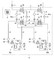
- FIG. 1 is a refrigeration cycle configuration diagram of a composite dual refrigeration cycle apparatus according to an embodiment used as a hot water supply system, for example.
- the composite binary refrigeration cycle apparatus has a first high-temperature side refrigeration in which, for example, R134a is circulated as a refrigerant in one housing K, hot water piping H that circulates water or hot water as a heat medium.
- the circuit R1a and the second high temperature side refrigeration circuit R1b, the first low temperature side refrigeration circuit R2a and the second low temperature side refrigeration circuit R2b that circulate, for example, R410A as a refrigerant, and the control device C are accommodated.
- the hot water pipe H has one end connected to a water supply source, a hot water storage tank, and the like, and the other end connected to a hot water storage side such as a hot water storage tank, a hot water tap.
- a pump 1 is connected to the hot water pipe H, and the water side flow path 3a of the first water / refrigerant heat exchanger 2A in the first high temperature side refrigeration circuit R1a with a predetermined interval on the downstream side thereof,
- the water side flow path 3b of the second water / refrigerant heat exchanger 2B in the second high temperature side refrigeration circuit R1b is connected.
- the first high temperature side refrigeration circuit R1a includes a discharge portion of the high temperature side compressor 5, the refrigerant side flow path 6 in the first water / heat exchanger 2A, the high temperature side receiver 7, the high temperature side expansion device 8, and the first.
- the high-temperature refrigerant flow path 10 of the cascade heat exchanger 9 and the suction part of the high-temperature side compressor 5 are sequentially connected by a refrigerant pipe P.
- the second high temperature side refrigeration circuit R1b includes a discharge portion of the high temperature side compressor 11, the refrigerant side flow path 12, the high temperature side receiver 13, the high temperature side expansion device 14, the second water / heat exchanger 2B.
- the high-temperature refrigerant flow path 16 of the cascade heat exchanger 15 and the suction portion of the high-temperature side compressor 11 are sequentially connected by the refrigerant pipe P.
- 1st low temperature side freezing circuit R2a has connected the discharge part of the low temperature side compressor 18 to the 1st port P1 of the four-way valve 19 through the refrigerant pipe P.
- the four-way valve 19 connects the second port P2 to the first low-temperature refrigerant flow path 33 of the second cascade heat exchanger 15, and the third port P3 is a first evaporator that is a first evaporator.
- the air heat exchanger 21 via refrigerant pipes P, respectively.
- the four-way valve 19 has its fourth port P4 connected to the suction portion of the low-temperature side compressor 18 through the accumulator 22 in series by the refrigerant pipe P.
- the first low-temperature refrigerant flow path 33 in the second cascade heat exchanger 15 is connected in series to the first low-temperature refrigerant flow path 20 in the first cascade heat exchanger 9 by the refrigerant pipe P. Further, the first low-temperature refrigerant flow path 20 in the first cascade heat exchanger 9 is sequentially connected to the low-temperature side receiver 23, the low-temperature side expansion device 24, and the air heat exchanger 21 by the refrigerant pipe P.
- a first blower fan FA is disposed opposite to the air heat exchanger 21.
- 2nd low temperature side freezing circuit R2b has connected the discharge part of the low temperature side compressor 25 to the 1st port P1 of the four-way valve 26 via the refrigerant pipe P.
- the four-way valve 26 connects the second port P2 to the second low-temperature refrigerant flow path 27 in the second cascade heat exchanger 15, and the third port P3 is a second evaporator that is a second evaporator.
- the air heat exchanger 28 via refrigerant pipes P, respectively.
- the four-way valve 26 has its fourth port connected to the suction portion of the low temperature side compressor 25 via the accumulator 29 in series by the refrigerant pipe P.
- the second low-temperature refrigerant flow path 27 in the second cascade heat exchanger 15 is connected in series to the second low-temperature refrigerant flow path 34 in the first cascade heat exchanger 9 by the refrigerant pipe P. .
- the second low-temperature refrigerant flow path 34 in the first cascade heat exchanger 9 is connected to the low-temperature side receiver 30, the low-temperature side expansion device 31, and the air heat exchanger 28 in the second low-temperature refrigeration circuit R 2 b.
- the pipes P are sequentially connected.
- a blower fan FB is disposed opposite to the air heat exchanger 28.
- FIG. 2 shows the configuration of the first cascade heat exchanger 9. Since the configuration of the first cascade heat exchanger 9 is the same as that of the second cascade heat exchanger 15, the latter description is omitted below.
- the first cascade heat exchanger 9 is provided on one side surface of the housing 40 at an end portion where the high-temperature refrigerant inlet 40a and the high-temperature refrigerant outlet 40b are separated from each other in the height direction.
- a refrigerant pipe P communicating with the high temperature side expansion device 8 is connected to the high temperature refrigerant introduction port 40a, and a refrigerant pipe P communicating with the suction portion of the high temperature side compressor 5 is connected to the high temperature refrigerant outlet port 40b.
- the housing 40 accommodates the high-temperature refrigerant flow path 10 therein.
- the high-temperature refrigerant flow path 10 is connected to the high-temperature refrigerant inlet 40a and the high-temperature refrigerant outlet 40b, and is paired with a pair of upper and lower main flow paths 41a and 41a parallel to each other and closed at opposite ends, and the main flow paths 41a, 41a, and a plurality of high-temperature refrigerant branch passages 41b parallel to each other at a predetermined interval in the horizontal direction in the figure.
- the housing 40 is provided with a first low-temperature refrigerant inlet 42a and a second low-temperature refrigerant inlet 43a on the other side surfaces at positions adjacent to each other. Furthermore, a first low-temperature refrigerant outlet 42 b and a second low-temperature refrigerant outlet 43 b are provided at positions adjacent to each other at positions separated on the same side surface of the housing 40.
- a refrigerant pipe P communicating with the first low-temperature refrigerant flow path 33 of the second cascade heat exchanger 15 is connected to the first low-temperature refrigerant inlet 42a, and the first low-temperature refrigerant outlet 42b is connected to the first low-temperature refrigerant outlet 42b.
- a refrigerant pipe P communicating with the low-temperature receiver 23 in the one low-temperature refrigeration circuit R2a is connected.
- a refrigerant pipe P communicating with the second low-temperature refrigerant flow path 27 of the second cascade heat exchanger 15 is connected to the second low-temperature refrigerant inlet 43a, and a second low-temperature refrigerant outlet 43b is connected to the second low-temperature refrigerant outlet 43b.
- a refrigerant pipe P communicating with the low-temperature receiver 30 in the second low-temperature refrigeration circuit R2b is connected.
- the housing 40 includes a first low-temperature refrigerant flow path 20 that communicates with the first low-temperature refrigerant inlet 42a and the first low-temperature refrigerant outlet 42b. Furthermore, a second low-temperature refrigerant flow path 34 communicating with the second low-temperature refrigerant inlet 43a and the second low-temperature refrigerant outlet 43b is formed in the housing 40.
- the first low-temperature refrigerant flow path 20 is connected to the first low-temperature refrigerant inlet port 42a and the first low-temperature refrigerant outlet port 42b, and is parallel to each other and closed at opposite ends in the figure. 44a, and a plurality of first low-temperature refrigerant branch flow paths 44b that communicate with each other between the pair of main flow paths 44a and 44a and are parallel to each other at a predetermined interval.
- the second low-temperature refrigerant channel 34 is connected to the second low-temperature refrigerant inlet 43a and the second low-temperature refrigerant outlet 43b, and is parallel to each other and closed between the main channel 45a and the main channel 45a. And a plurality of second low-temperature refrigerant branch flow paths 45b that are parallel to each other at a predetermined interval.
- the first low-temperature refrigerant branch channel 44 b that constitutes the first low-temperature refrigerant channel 20 and the second low-temperature refrigerant.
- the second low-temperature refrigerant branch flow paths 45b constituting the flow path 34 are provided in parallel at a predetermined interval.
- the first low-temperature refrigerant branch flow path 44b is provided on one surface side of the high-temperature refrigerant branch flow path 41b, and the second low-temperature refrigerant branch flow path 45b is provided on the other surface side.
- the two low-temperature refrigerant branch channels 44b and 45b are alternately arranged with respect to the high-temperature refrigerant branch channel 41b. For this reason, the flow of the high-temperature refrigerant and the low-temperature refrigerant becomes an opposite flow, and the heat transfer effect is improved.
- the flow path for the high-temperature refrigerant is provided inside the housing 40 and the low-temperature refrigerant flow path is formed on the outside thereof, the temperature drop of the high-temperature refrigerant can be reduced.
- the casing 40 constituting the first cascade heat exchanger 9 and the material of the partition member for partitioning each refrigerant flow path are made of materials having excellent thermal conductivity.
- the high-temperature refrigerant, the first low-temperature refrigerant, and the second low-temperature refrigerant efficiently exchange heat by the above-described flow path configuration of the first cascade heat exchanger 9 and selection of the constituent materials, thereby improving the heat exchange efficiency. be able to.
- the high-temperature refrigerant inlet 40a, the high-temperature refrigerant outlet 40b, the first low-temperature refrigerant inlet 42a, the second low-temperature refrigerant inlet 43a, the first low-temperature refrigerant outlet 42b, and the second low-temperature refrigerant outlet 43b are In addition to the above configuration, each of the side surfaces of the housing 40 may be provided, and there is no limitation.
- the high temperature refrigerant inlet 40a, the high temperature refrigerant outlet 40b, the first low temperature refrigerant inlet 42a, the second low temperature refrigerant inlet 43a, the first low temperature refrigerant outlet 42b, and the second low temperature refrigerant outlet 43b are: All may be provided on the same side surface of the housing 40.
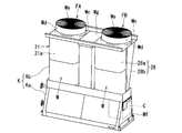
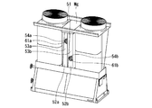
- FIGS. 3 to 5 are composite dual refrigeration cycle apparatus diagrams, FIG. 3 is an external perspective view of the composite dual refrigeration cycle apparatus according to the present embodiment, FIG. 4 is a front view thereof, and FIG. 5 is a side view thereof. is there.
- the composite binary refrigeration cycle apparatus has a housing K shown in FIG. 1 having an overall drum shape in a side view.
- the housing K includes a lower housing Ka having a substantially trapezoidal side surface and a substantially V-shaped upper housing Kb disposed integrally or integrally on the lower housing Ka.
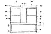
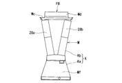
- the upper housing Kb is composed of a plurality (here, two sets) of heat exchanger modules M and M and the same number of blower fans FA and FB.
- One set of heat exchanger modules M are arranged such that a pair (two) of air heat exchangers 21a and 21b, 28a and 28b face each other, and each of these air heat exchangers 21a and 21b, 28a and 28b. It is comprised by arrange
- Each heat exchanger module M is provided with a top plate Mc at its upper end, and the blower fans FA and FB are attached to the top plate Mc at positions facing each other between the heat exchanger modules M. Cylindrical air outlets Md and Md are projected above the top plate Mc, and the projecting end surfaces of the air outlets Md and Md are covered with fan guards Me and Me, respectively.
- the air heat exchangers 21a and 21b, and 28a and 28b constituting the heat exchanger module M are opposed to each other so that the top plate Mc side, which is the upper end portion, is wide and the lower housing Ka side is narrow and close to each other. Are inclined with respect to each other so as to be substantially V-shaped.
- a partition wall portion Mg is provided between the heat exchanger modules M and M so as not to affect the heat between the heat exchanger modules M and M.
- the lower housing Ka is configured in the machine room Mf.
- the machine room Mf includes refrigeration cycle components constituting the first and second high temperature side refrigeration circuits R1a and R1b and the first and second low temperature side refrigeration circuits R2a and R2b shown in FIG.
- the control device C is accommodated.
- the control device C has a function of controlling the entire operation of the composite binary refrigeration cycle device. For example, an ON / OFF control function for receiving ON / OFF control of the operation of the refrigeration cycle in response to an operation signal from an operation device such as an operation panel (not shown), a switching function of the operation mode (heating / defrosting operation mode) , The function of detecting frost formation of the second air heat exchangers 21 and 28, the function of controlling the refrigerant circulation flow rate by the opening degree control of the high-temperature side and low-temperature side expansion devices 8, 14, 24 and 31, first and second Of the high-temperature side compressors 5 and 11, the first and second low-temperature side compressors 18 and 25, and the first and second blower fans FA and FB per unit time (hereinafter simply referred to as the number of revolutions).
- an ON / OFF control function for receiving ON / OFF control of the operation of the refrigeration cycle in response to an operation signal from an operation device such as an operation panel (not shown), a switching function of the operation mode
- control device C includes the first and second high temperature side compressors 5 and 11, the first and second low temperature side compressors 18 and 25, and the first and second blower fans FA, Six inverter boards (not shown) for driving each of the FBs are stored.
- the four-way valves 19 and 26 of the first and second low temperature side refrigeration circuits R2a and R2b are in the heating operation mode.
- the opening degree of each expansion device 8, 14, 24, 31 is controlled to a predetermined opening degree.
- the compressors 5, 11, 18, 25 and the blower fans FA and FB are started and operated at a required rotational speed.
- the refrigerant is led to the first high temperature side refrigeration circuit R1a, the second high temperature side refrigeration circuit R1b, the first low temperature side refrigeration circuit R2a, and the second low temperature side refrigeration circuit R2b, and sequentially circulates. .
- the refrigerant R134a is converted into the high temperature side compressor 5—the refrigerant side flow path 6—the high temperature side receiver 7—the high temperature side expansion device 8 in the first water / refrigerant heat exchanger 2A.
- the high-temperature refrigerant flow path 10 in the first cascade heat exchanger 9-the high-temperature side compressor 5- are guided and circulated in this order.
- the refrigerant side flow path 6 in the first water / refrigerant heat exchanger 2A acts as a condenser, and the high temperature refrigerant flow path 10 in the first cascade heat exchanger 9 acts as an evaporator.
- the refrigerant R410A discharged from the low-temperature side compressor 18 is transferred to the first low-temperature refrigerant flow path 33-first cascade heat in the four-way valve 19-second cascade heat exchanger 15.
- the first low-temperature refrigerant flow path 20 the low-temperature side receiver 23, the low-temperature side expansion device 24, the first air heat exchanger 21, the four-way valve 19, the accumulator 22, and the low-temperature side compressor 18 are led and circulated in this order. To do.
- the refrigerant R134a is supplied from the high temperature side compressor 11—the refrigerant side flow path 12—the high temperature side receiver 13—the high temperature side expansion device 14—in the second water / refrigerant heat exchanger 2B.
- the high-temperature refrigerant flow path 16 and the high-temperature side compressor 11 are led in order and circulated.
- the refrigerant side flow path 12 in the second water / refrigerant heat exchanger 2B acts as a condenser, and the high temperature refrigerant flow path 16 in the second cascade heat exchanger 15 acts as an evaporator.
- the refrigerant R410A discharged from the low-temperature side compressor 25 is transferred to the second low-temperature refrigerant flow path 27-first cascade heat in the four-way valve 26-second cascade heat exchanger 15.
- the second low-temperature refrigerant flow path 34, the low-temperature side receiver 30, the low-temperature side expansion device 31, the second air heat exchanger 28, the four-way valve 26, the accumulator 29, and the low-temperature side compressor 25 are led and circulated in this order. To do.
- the first low-temperature refrigerant flow path 20 and the second low-temperature refrigerant flow path 34 act as a condenser, and as described above, the high-temperature refrigerant of the first high-temperature side refrigeration circuit R1a.
- the flow path 10 acts as an evaporator. That is, the refrigerant condenses in the first and second low-temperature refrigerant flow paths 20 and 34 to release condensation heat, and the condensation heat evaporates while absorbing heat in the high-temperature refrigerant flow path 10.
- the water or hot water led to the hot water pipe H through the pump 1 is condensed in the first high temperature side refrigeration circuit R1a in the water side flow path 3a of the first water / refrigerant heat exchanger 2A.
- High-temperature condensation heat is absorbed from the refrigerant-side flow path 6 of the water / refrigerant heat exchanger 2A, and rises to a high temperature.
- the hot water having a high temperature in the water side channel 3a of the first water / refrigerant heat exchanger 2A is guided to the water side channel 3b of the second water / refrigerant heat exchanger 2B.
- the first low-temperature refrigerant flow path 33 and the second low-temperature refrigerant flow path 27 act as a condenser, and as described above, the high-temperature refrigerant of the second high-temperature side refrigeration circuit R1b.
- the channel 16 acts as an evaporator. That is, the refrigerant condenses in the first and second low-temperature refrigerant flow paths 33 and 27 to release condensation heat, and the condensation heat evaporates while absorbing heat in the high-temperature refrigerant flow path 16.
- the hot water guided from the first water / refrigerant heat exchanger 2A to the water-side flow path 3b of the second water / refrigerant heat exchanger 2B is condensed into the first water by the second high-temperature side refrigeration circuit R1b.
- the high-temperature condensation heat is further absorbed from the refrigerant-side flow path 12 of the refrigerant heat exchanger 2B, and rises to a higher temperature. That is, the temperature rises to the set temperature in the water-side flow path 3b of the second water / refrigerant heat exchanger 2B.
- the hot water that has risen to the set temperature from the second water / refrigerant heat exchanger 2B is led to the hot water outlet such as a hot water storage tank or hot water tap. Then, it is led again to the first and second water / refrigerant heat exchangers 2A and 2B and heated and circulated to the hot water storage tank or discharged directly to the hot water tap.
- the controller C needs to switch the four-way valve 19 of the first low-temperature side refrigeration circuit R2b to the defrosting operation side and perform the defrosting operation of the first and second air heat exchangers 21 and 28. is there.
- the defrosting operation of the first and second air heat exchangers 21 and 28 is not performed simultaneously. For example, first, the defrosting operation of the first air heat exchanger 21 in the first low-temperature side refrigeration circuit R2a is performed. After the defrosting operation is completed, the defrosting operation of the second air heat exchanger 28 in the second low temperature side refrigeration circuit R2b is performed.
- the defrosting operation of the second air heat exchanger 28 may be performed first, and the defrosting operation of the first air heat exchanger 21 may be performed after the defrosting is completed.
- the control device C switches the four-way valve 19 of the first low temperature side refrigeration circuit R2a to the reverse cycle.
- the four-way valve 26 of the second low temperature side refrigeration circuit R2b is held in the heating operation.
- the operation of the compressor 5 of the first high temperature side refrigeration circuit R1a and the compressor 11 of the second high temperature side refrigeration circuit R1b is stopped by the control device C or is operated at a slow speed.
- the operating frequency of the compressor 25 of the second low temperature side refrigeration circuit R2b during the heating operation is based on the operating frequency of the compressors 18 and 25 when both the first and second low temperature side refrigeration circuits R2a and R2b are heated.
- the frequency is increased to a higher operating frequency.
- the rotation speed of the second blower fan FB is increased to the maximum rotation speed, the evaporation temperature is increased, and the capacity of the refrigeration cycle of the second low-temperature side refrigeration circuit R2b is increased.
- the pump 1 since the hot water is not heated, the pump 1 is stopped. However, the operation of the pump 1 may be continued when it is necessary to continuously circulate the hot water due to a request from the user side.
- the high-temperature and high-pressure refrigerant discharged from the low-temperature side compressor 18 is directly led to the first air heat exchanger 21 through the four-way valve 19 and condensed. The heat of condensation is released to melt the attached frost.
- the refrigerant evaporates in the first low-temperature refrigerant flow path 20 in the first cascade heat exchanger 9 and the first low-temperature refrigerant flow path 33 in the second cascade heat exchanger 15, but the second low-temperature refrigerant flow path Since the side refrigeration circuit R2b continues the heating operation, the amount of heat corresponding to the heat of evaporation is transferred to the second low-temperature refrigerant flow path 34 in the first cascade heat exchanger 9 and the second cascade heat exchanger. 15 continues to supply heat to the second low-temperature refrigerant flow path 27 in the form of condensation heat.
- the first cascade heat exchange is performed.
- the first low-temperature refrigerant flow path 20 and the second low-temperature refrigerant flow path 34 in the vessel 9 are not adjacent to each other, the protrusions formed on the plate of the heat exchanger are in metal contact with each other. Heat can be exchanged by heat conduction of the plate metal.
- the first low-temperature refrigerant flow path 33 and the second low-temperature refrigerant flow path 27 in the second cascade heat exchanger 15 can similarly conduct heat.
- the compressor 5 of the first high temperature side refrigeration circuit R1a and the compressor 11 of the second high temperature side refrigeration circuit R1b are operated at a low speed by heating operation during defrosting, the first The first low-temperature refrigerant flow path 10 between the first low-temperature refrigerant flow path 20 and the second low-temperature refrigerant flow path 34 in the cascade heat exchanger 9 and the first low-temperature refrigerant in the second cascade heat exchanger 15.
- the first low-temperature refrigerant flow paths 20 and 33 in the first low-temperature side refrigeration circuit R2a being defrosted are in the heating operation.
- the second low-temperature refrigerant circuit R2b in the second low-temperature side refrigeration circuit R2b absorbs heat from each of the second low-temperature refrigerant flow paths 34 and 27 to constitute a binary cycle during defrosting.
- the capacity of the compressor 25 of the second low-temperature refrigerant circuit R2b during the heating operation is increased and the second blower fan FB is operating at the maximum rotation speed, each second low-temperature refrigerant flow path 34, The amount of heat absorbed at 27 can be increased.
- the defrosting can be completed in a short time.
- warm water is not used as a heat source, an extreme temperature drop in the warm water in the warm water pipe H during defrosting can be prevented.
- the operation of the pump 1 since the operation of the pump 1 can be stopped, the outflow of unheated warm water can be prevented. However, the operation of the pump 1 may be continued when it is necessary to continuously circulate the hot water due to a request from the user side.
- the defrosting of the first air heat exchanger 21 When the defrosting of the first air heat exchanger 21 is completed, the process moves to the defrosting of the second air heat exchanger 28. That is, the four-way valve 19 of the first low-temperature side refrigeration circuit R2a is switched to the normal heating operation, and the four-way valve 26 of the second low-temperature side refrigeration circuit R2b is switched to the reverse cycle.
- the high temperature and high pressure refrigerant discharged from the low temperature side compressor 25 is directly led to the second air heat exchanger 28 via the four-way valve 26. It condenses and releases condensation heat to melt the attached frost.
- the refrigerant evaporates in the second low-temperature refrigerant flow path 34 in the first cascade heat exchanger 9 and the second low-temperature refrigerant flow path 27 in the second cascade heat exchanger 15, but the first low-temperature side refrigeration circuit Since R2a is in a heating operation, the amount of heat corresponding to the heat of evaporation is converted into the first low-temperature refrigerant flow path 20 in the first cascade heat exchanger 9 and the first amount in the second cascade heat exchanger 15. It continues to be supplied as condensation heat to the low-temperature refrigerant flow path 33.
- the second low-temperature refrigerant flow paths 34 and 27 in the second low-temperature side refrigeration circuit R2b being defrosted are in the heating operation. Heat is absorbed from the first low-temperature refrigerant flow paths 20 and 33 in the first low-temperature side refrigeration circuit R2a to constitute a two-way cycle during defrosting.
- the heat supply source is secured in this way, defrosting can be completed in a short time. Moreover, since warm water is not used as a heat source, an extreme temperature drop in the warm water in the warm water pipe H during defrosting can be prevented. Since the pump 1 can be stopped, the outflow of warm water that is not heated can be prevented. However, the operation of the pump 1 may be continued when it is necessary to continuously circulate the hot water due to a request from the user side.
- the four-way valve 26 of the second low temperature side refrigeration circuit R2b is switched to the normal heating operation, and the compressor 5 of the first high temperature side refrigeration circuit R1a is switched. If the compressor 11 of the second high temperature side refrigeration circuit R1b and the pump 1 are stopped, the pump 1 may be driven. Therefore, in the first and second high temperature side refrigeration circuits R1a and R1b, the four-way valve and the accumulator are not required, and the configuration can be simplified.
- defrosting can be completed in a short time.
- the temperature of the compressor is not lowered more than necessary, the capacity rises quickly when the heating operation is resumed after defrosting.
- the pump can be stopped at the time of defrosting, and it is possible to prevent warm water below the set temperature from flowing out.
- the compressors 18 and 25 of the other first and second low temperature side refrigeration circuits R2a and R2b that are heated are operated. Since the operating frequency is higher than the operating frequency when both the first and second low temperature side refrigeration circuits R2a and R2b are operated for heating, the first and second blower fans FA and FB are operating at the maximum rotational speed. The defrosting time can be shortened.
- the first and second air heat exchangers 21 and 28 (heat exchanger modules M and M) are separated from each other by the partition wall portion Mg, the first and second low-temperature side refrigeration circuits R2a and R2b During one defrosting operation, the other air heat exchangers 21 and 28 are not affected by heat and the defrosting time can be shortened.
- this empty space is a space that can appropriately accommodate a desired optional device such as a harmonic reduction device 60 described later, for example.
- the partition part Mg has the same structure by the front side and a back side, and demonstrates below by illustrating the front side.
- the partition wall portion Mg When accommodating the harmonic reduction device 60 in the partition wall portion Mg, the partition wall portion Mg is closed by an outer lid 50 in which a plurality of sheet metal air holes 50a are formed as shown in FIG.
- left and right partition plates 51 are provided to partition the partition wall portion Mg left and right at the left and right center in FIG. 7, and two harmonics are reduced in each of the chambers partitioned left and right as shown in FIG.
- the device 60 is arranged side by side in the vertical direction. That is, a total of four harmonic reduction devices 60a to 60d are accommodated in the partition wall portion Mg.
- the harmonic reduction devices 60a to 60d are, for example, 18-pulse rectifiers or 12-pulse rectifiers, and can be connected to the inverter boards for the compressors housed in the control device C to reduce harmonics.
- the harmonic reduction devices 60a to 60d are each provided with exhaust heat fans 61a to 61d for discharging the heat inside, and a plurality of ventilation holes (not shown) are formed on the side surfaces.
- the inner lids 52a to 52d are provided inside the partition wall portion Mg so as to hide the harmonic reduction devices 54a to 54d.
- a gap is provided between the inner lids 52a to 52d and the outer lid 50, and the air discharged from the harmonic reduction devices 60a to 60d is discharged from the vent hole 50a of the outer lid 50 to the outside of the partition wall portion Mg. Ventilation paths 53a to 53d are formed.
- the inner lids 52a to 53d are provided with fan holes 54a to 54d facing the exhaust heat fans 61a to 61d in a state where the harmonic reduction devices 60a to 60d are accommodated in the partition wall portion Mg.
- the air discharged from the heat exhaust fans 61a to 61d is discharged to the ventilation paths 53a to 53d through the fan holes 54a to 54d.
- Adjacent ventilation paths 53 a and 53 b (back side 53 c and 53 d) are partitioned by a left and right partition plate 51. That is, four independent ventilation paths 53a to 53d are formed.
- the harmonic reduction device 60a arranged at the upper left stage is connected to the inverter board for the low temperature compressor 18 of the low temperature side refrigeration circuit R2a, and the harmonic reduction device 60b arranged at the lower right stage is the high temperature side refrigeration. It is connected to the inverter board for the high temperature side compressor 5 of the circuit R1a.
- the harmonic reduction device 60c disposed in the upper right stage is connected to the inverter board for the low temperature side compressor 25 of the low temperature side refrigeration circuit R2b, and the harmonic reduction device 60d disposed in the lower left stage is the high temperature side refrigeration circuit R1b. It is connected to the inverter board for the high temperature side compressor 11.
- the respective harmonic reduction devices 60a to 60d are arranged corresponding to the four independent ventilation paths 53a to 53d, so that they are not affected by the exhaust heat of the other harmonic reduction devices. .
- harmonic reduction device 60 is incorporated as necessary, and may be incorporated in up to four units or may not be incorporated in one unit.
- the harmonic reduction device 60 can be selectively disposed on the inverter board as necessary.
Abstract
La présente invention concerne un dispositif à double cycle de réfrigération composite équipé : de deux circuits de réfrigération côté haute température comprenant respectivement des échangeurs de chaleur à eau/réfrigérant pour l'échange thermique de l'eau et d'un réfrigérant évacués à partir d'un compresseur sur le côté haute température, et de deux circuits de réfrigération côté basse température comportant respectivement des évaporateurs comprenant des échangeurs de chaleur à air munis de ventilateurs, les circuits étant intégrés dans le même châssis ; et de conduites d'eau chaude conçues pour permettre un échange thermique à partir des circuits respectifs de réfrigération côté haute température vers les circuits respectifs de réfrigération côté basse température au moyen d'un échangeur de chaleur en cascade, permettant la circulation d'eau froide ou d'eau chaude vers le canal d'écoulement côté eau froide des échangeurs de chaleur à eau/réfrigérant des circuits de réfrigération côté haute température, l'intérieur du châssis étant équipé d'un dispositif de commande pour la commande globale du fonctionnement du dispositif. Le dispositif à double cycle de réfrigération composite selon l'invention est caractérisé en ce qu'il est conçu de sorte que les deux circuits de réfrigération côté basse température soient raccordés au dispositif de commande, et lorsque l'un des circuits de réfrigération côté basse température effectue une opération de dégivrage de l'évaporateur associé, l'autre circuit de réfrigération côté basse température est commandé de façon à effectuer un échange thermique avec l'échangeur de chaleur en cascade, tandis que la vitesse de rotation du ventilateur soufflant de l'autre circuit de réfrigération côté basse température est commandée à une vitesse de rotation supérieure à la vitesse de rotation du ventilateur soufflant pendant une opération de chauffage des deux circuits de réfrigération côté basse température conjointement.
Priority Applications (2)
| Application Number | Priority Date | Filing Date | Title |
|---|---|---|---|
| CN201380017567.3A CN104204693B (zh) | 2012-04-04 | 2013-04-01 | 复合二元制冷循环装置 |
| JP2014509153A JP5830602B2 (ja) | 2012-04-04 | 2013-04-01 | 複合二元冷凍サイクル装置 |
Applications Claiming Priority (2)
| Application Number | Priority Date | Filing Date | Title |
|---|---|---|---|
| JP2012-085611 | 2012-04-04 | ||
| JP2012085611 | 2012-04-04 |
Publications (1)
| Publication Number | Publication Date |
|---|---|
| WO2013151005A1 true WO2013151005A1 (fr) | 2013-10-10 |
Family
ID=49300488
Family Applications (1)
| Application Number | Title | Priority Date | Filing Date |
|---|---|---|---|
| PCT/JP2013/059912 WO2013151005A1 (fr) | 2012-04-04 | 2013-04-01 | Dispositif à double cycle de réfrigération composite |
Country Status (3)
| Country | Link |
|---|---|
| JP (1) | JP5830602B2 (fr) |
| CN (1) | CN104204693B (fr) |
| WO (1) | WO2013151005A1 (fr) |
Cited By (7)
| Publication number | Priority date | Publication date | Assignee | Title |
|---|---|---|---|---|
| WO2017217383A1 (fr) * | 2016-06-14 | 2017-12-21 | 東芝キヤリア株式会社 | Dispositif à cycle de réfrigération |
| CN108800664A (zh) * | 2017-04-27 | 2018-11-13 | 华东交通大学 | 一种基于地源技术的高效冷库与干燥库复合系统 |
| EP3287706A4 (fr) * | 2015-04-21 | 2019-01-16 | Mitsubishi Electric Corporation | Unité source de chaleur |
| WO2021024404A1 (fr) * | 2019-08-07 | 2021-02-11 | 三菱電機株式会社 | Unité de refroidissement et système de climatisation |
| JP2021527794A (ja) * | 2018-06-19 | 2021-10-14 | エヌ.エー.エム.テクノロジー リミテッド | マルチカスケード冷却システム |
| EP3995763A4 (fr) * | 2019-07-03 | 2022-07-20 | Mitsubishi Electric Corporation | Dispositif à cycle frigorifique |
| WO2023190233A1 (fr) * | 2022-03-30 | 2023-10-05 | 株式会社富士通ゼネラル | Dispositif pompe à chaleur |
Families Citing this family (2)
| Publication number | Priority date | Publication date | Assignee | Title |
|---|---|---|---|---|
| CN107314424A (zh) * | 2017-08-07 | 2017-11-03 | 宝莲华新能源技术(上海)股份有限公司 | 一种适用于北方冬季供暖的高效热泵采暖机组 |
| CN112154294A (zh) * | 2018-05-31 | 2020-12-29 | 三菱电机株式会社 | 室外机以及制冷循环装置 |
Citations (6)
| Publication number | Priority date | Publication date | Assignee | Title |
|---|---|---|---|---|
| JPH02583U (fr) * | 1988-06-09 | 1990-01-05 | ||
| JPH09269155A (ja) * | 1996-01-31 | 1997-10-14 | Daikin Ind Ltd | 二元冷凍装置 |
| JP2001280734A (ja) * | 2000-03-31 | 2001-10-10 | Sanyo Electric Co Ltd | 冷風発生装置 |
| JP2005282869A (ja) * | 2004-03-26 | 2005-10-13 | Mitsubishi Heavy Ind Ltd | 複合型冷凍サイクル設備及びその運転方法 |
| JP2007198693A (ja) * | 2006-01-27 | 2007-08-09 | Mayekawa Mfg Co Ltd | カスケード型ヒートポンプシステム |
| CN101210748A (zh) * | 2006-12-28 | 2008-07-02 | 苏宇贵 | 空调热水复合机 |
-
2013
- 2013-04-01 WO PCT/JP2013/059912 patent/WO2013151005A1/fr active Application Filing
- 2013-04-01 JP JP2014509153A patent/JP5830602B2/ja active Active
- 2013-04-01 CN CN201380017567.3A patent/CN104204693B/zh active Active
Patent Citations (6)
| Publication number | Priority date | Publication date | Assignee | Title |
|---|---|---|---|---|
| JPH02583U (fr) * | 1988-06-09 | 1990-01-05 | ||
| JPH09269155A (ja) * | 1996-01-31 | 1997-10-14 | Daikin Ind Ltd | 二元冷凍装置 |
| JP2001280734A (ja) * | 2000-03-31 | 2001-10-10 | Sanyo Electric Co Ltd | 冷風発生装置 |
| JP2005282869A (ja) * | 2004-03-26 | 2005-10-13 | Mitsubishi Heavy Ind Ltd | 複合型冷凍サイクル設備及びその運転方法 |
| JP2007198693A (ja) * | 2006-01-27 | 2007-08-09 | Mayekawa Mfg Co Ltd | カスケード型ヒートポンプシステム |
| CN101210748A (zh) * | 2006-12-28 | 2008-07-02 | 苏宇贵 | 空调热水复合机 |
Cited By (13)
| Publication number | Priority date | Publication date | Assignee | Title |
|---|---|---|---|---|
| EP3287706A4 (fr) * | 2015-04-21 | 2019-01-16 | Mitsubishi Electric Corporation | Unité source de chaleur |
| US10436458B2 (en) | 2015-04-21 | 2019-10-08 | Mitsubishi Electric Corporation | Heat source unit |
| JPWO2017217383A1 (ja) * | 2016-06-14 | 2019-01-17 | 東芝キヤリア株式会社 | 冷凍サイクル装置 |
| EP3470754A4 (fr) * | 2016-06-14 | 2020-02-26 | Toshiba Carrier Corporation | Dispositif à cycle de réfrigération |
| WO2017217383A1 (fr) * | 2016-06-14 | 2017-12-21 | 東芝キヤリア株式会社 | Dispositif à cycle de réfrigération |
| CN108800664A (zh) * | 2017-04-27 | 2018-11-13 | 华东交通大学 | 一种基于地源技术的高效冷库与干燥库复合系统 |
| JP2021527794A (ja) * | 2018-06-19 | 2021-10-14 | エヌ.エー.エム.テクノロジー リミテッド | マルチカスケード冷却システム |
| EP3995763A4 (fr) * | 2019-07-03 | 2022-07-20 | Mitsubishi Electric Corporation | Dispositif à cycle frigorifique |
| JPWO2021024404A1 (ja) * | 2019-08-07 | 2021-12-23 | 三菱電機株式会社 | チリングユニット及び空気調和システム |
| WO2021024404A1 (fr) * | 2019-08-07 | 2021-02-11 | 三菱電機株式会社 | Unité de refroidissement et système de climatisation |
| WO2023190233A1 (fr) * | 2022-03-30 | 2023-10-05 | 株式会社富士通ゼネラル | Dispositif pompe à chaleur |
| JP2023147886A (ja) * | 2022-03-30 | 2023-10-13 | 株式会社富士通ゼネラル | ヒートポンプ装置 |
| JP7380739B2 (ja) | 2022-03-30 | 2023-11-15 | 株式会社富士通ゼネラル | ヒートポンプ装置 |
Also Published As
| Publication number | Publication date |
|---|---|
| CN104204693B (zh) | 2016-06-01 |
| JP5830602B2 (ja) | 2015-12-09 |
| CN104204693A (zh) | 2014-12-10 |
| JPWO2013151005A1 (ja) | 2015-12-17 |
Similar Documents
| Publication | Publication Date | Title |
|---|---|---|
| JP5830602B2 (ja) | 複合二元冷凍サイクル装置 | |
| KR100810870B1 (ko) | 급탕장치 | |
| US9528732B2 (en) | Heat pump apparatus | |
| WO2013027757A1 (fr) | Appareil à cycle de réfrigération binaire combiné | |
| US20130167559A1 (en) | Heat pump and control method thereof | |
| JP6883186B2 (ja) | ヒートポンプシステム | |
| WO2011045976A1 (fr) | Système d'alimentation en eau chaude pour climatiseur | |
| JP4298990B2 (ja) | 二酸化炭素を冷媒として用いた冷凍装置 | |
| WO2013175731A1 (fr) | Dispositif de pompe à chaleur géothermique | |
| EP2629031B1 (fr) | Système de pompe à chaleur à gaz | |
| JP2005299935A (ja) | 空気調和装置 | |
| US7228700B2 (en) | Heating/cooling system | |
| WO2014076891A1 (fr) | Dispositif de test environnemental | |
| JP5157307B2 (ja) | 自動販売機 | |
| WO2006103968A1 (fr) | Dispositif de regulation de l'humidite | |
| KR20200065180A (ko) | 수냉식 컨덴서와 이를 이용하는 전기자동차용 냉난방 시스템 | |
| US20190219181A1 (en) | Switch valve | |
| KR100849613B1 (ko) | 온수 급탕 및 바닥 난방이 가능한 고효율 히트 펌프식냉난방 장치 | |
| JP2013040694A (ja) | 冷凍装置 | |
| KR20210011171A (ko) | 차량용 히트 펌프 시스템 | |
| KR101275580B1 (ko) | 공기조화기 및 그 운전방법 | |
| WO2013046723A1 (fr) | Système d'alimentation en eau chaude et de climatisation | |
| JP5768382B2 (ja) | 冷却装置 | |
| KR20200064362A (ko) | 수냉식 컨덴서와 이를 이용하는 전기자동차용 냉난방 시스템 | |
| KR101543747B1 (ko) | 다단 열교환패스 구조를 갖는 콤팩트형 히트펌프 시스템 |
Legal Events
| Date | Code | Title | Description |
|---|---|---|---|
| 121 | Ep: the epo has been informed by wipo that ep was designated in this application |
Ref document number: 13772806 Country of ref document: EP Kind code of ref document: A1 |
|
| ENP | Entry into the national phase |
Ref document number: 2014509153 Country of ref document: JP Kind code of ref document: A |
|
| NENP | Non-entry into the national phase |
Ref country code: DE |
|
| 122 | Ep: pct application non-entry in european phase |
Ref document number: 13772806 Country of ref document: EP Kind code of ref document: A1 |