WO2013151005A1 - Composite dual refrigeration cycle device - Google Patents
Composite dual refrigeration cycle device Download PDFInfo
- Publication number
- WO2013151005A1 WO2013151005A1 PCT/JP2013/059912 JP2013059912W WO2013151005A1 WO 2013151005 A1 WO2013151005 A1 WO 2013151005A1 JP 2013059912 W JP2013059912 W JP 2013059912W WO 2013151005 A1 WO2013151005 A1 WO 2013151005A1
- Authority
- WO
- WIPO (PCT)
- Prior art keywords
- low
- temperature
- temperature side
- heat exchanger
- flow path
- Prior art date
Links
Images


Classifications
-
- F—MECHANICAL ENGINEERING; LIGHTING; HEATING; WEAPONS; BLASTING
- F25—REFRIGERATION OR COOLING; COMBINED HEATING AND REFRIGERATION SYSTEMS; HEAT PUMP SYSTEMS; MANUFACTURE OR STORAGE OF ICE; LIQUEFACTION SOLIDIFICATION OF GASES
- F25B—REFRIGERATION MACHINES, PLANTS OR SYSTEMS; COMBINED HEATING AND REFRIGERATION SYSTEMS; HEAT PUMP SYSTEMS
- F25B7/00—Compression machines, plants or systems, with cascade operation, i.e. with two or more circuits, the heat from the condenser of one circuit being absorbed by the evaporator of the next circuit
-
- F—MECHANICAL ENGINEERING; LIGHTING; HEATING; WEAPONS; BLASTING
- F25—REFRIGERATION OR COOLING; COMBINED HEATING AND REFRIGERATION SYSTEMS; HEAT PUMP SYSTEMS; MANUFACTURE OR STORAGE OF ICE; LIQUEFACTION SOLIDIFICATION OF GASES
- F25B—REFRIGERATION MACHINES, PLANTS OR SYSTEMS; COMBINED HEATING AND REFRIGERATION SYSTEMS; HEAT PUMP SYSTEMS
- F25B13/00—Compression machines, plants or systems, with reversible cycle
-
- F—MECHANICAL ENGINEERING; LIGHTING; HEATING; WEAPONS; BLASTING
- F25—REFRIGERATION OR COOLING; COMBINED HEATING AND REFRIGERATION SYSTEMS; HEAT PUMP SYSTEMS; MANUFACTURE OR STORAGE OF ICE; LIQUEFACTION SOLIDIFICATION OF GASES
- F25B—REFRIGERATION MACHINES, PLANTS OR SYSTEMS; COMBINED HEATING AND REFRIGERATION SYSTEMS; HEAT PUMP SYSTEMS
- F25B47/00—Arrangements for preventing or removing deposits or corrosion, not provided for in another subclass
- F25B47/02—Defrosting cycles
- F25B47/022—Defrosting cycles hot gas defrosting
- F25B47/025—Defrosting cycles hot gas defrosting by reversing the cycle
-
- F—MECHANICAL ENGINEERING; LIGHTING; HEATING; WEAPONS; BLASTING
- F25—REFRIGERATION OR COOLING; COMBINED HEATING AND REFRIGERATION SYSTEMS; HEAT PUMP SYSTEMS; MANUFACTURE OR STORAGE OF ICE; LIQUEFACTION SOLIDIFICATION OF GASES
- F25B—REFRIGERATION MACHINES, PLANTS OR SYSTEMS; COMBINED HEATING AND REFRIGERATION SYSTEMS; HEAT PUMP SYSTEMS
- F25B2339/00—Details of evaporators; Details of condensers
- F25B2339/04—Details of condensers
- F25B2339/047—Water-cooled condensers
-
- F—MECHANICAL ENGINEERING; LIGHTING; HEATING; WEAPONS; BLASTING
- F25—REFRIGERATION OR COOLING; COMBINED HEATING AND REFRIGERATION SYSTEMS; HEAT PUMP SYSTEMS; MANUFACTURE OR STORAGE OF ICE; LIQUEFACTION SOLIDIFICATION OF GASES
- F25B—REFRIGERATION MACHINES, PLANTS OR SYSTEMS; COMBINED HEATING AND REFRIGERATION SYSTEMS; HEAT PUMP SYSTEMS
- F25B2400/00—General features or devices for refrigeration machines, plants or systems, combined heating and refrigeration systems or heat-pump systems, i.e. not limited to a particular subgroup of F25B
- F25B2400/06—Several compression cycles arranged in parallel
-
- F—MECHANICAL ENGINEERING; LIGHTING; HEATING; WEAPONS; BLASTING
- F25—REFRIGERATION OR COOLING; COMBINED HEATING AND REFRIGERATION SYSTEMS; HEAT PUMP SYSTEMS; MANUFACTURE OR STORAGE OF ICE; LIQUEFACTION SOLIDIFICATION OF GASES
- F25B—REFRIGERATION MACHINES, PLANTS OR SYSTEMS; COMBINED HEATING AND REFRIGERATION SYSTEMS; HEAT PUMP SYSTEMS
- F25B2600/00—Control issues
- F25B2600/11—Fan speed control
- F25B2600/112—Fan speed control of evaporator fans
-
- Y—GENERAL TAGGING OF NEW TECHNOLOGICAL DEVELOPMENTS; GENERAL TAGGING OF CROSS-SECTIONAL TECHNOLOGIES SPANNING OVER SEVERAL SECTIONS OF THE IPC; TECHNICAL SUBJECTS COVERED BY FORMER USPC CROSS-REFERENCE ART COLLECTIONS [XRACs] AND DIGESTS
- Y02—TECHNOLOGIES OR APPLICATIONS FOR MITIGATION OR ADAPTATION AGAINST CLIMATE CHANGE
- Y02B—CLIMATE CHANGE MITIGATION TECHNOLOGIES RELATED TO BUILDINGS, e.g. HOUSING, HOUSE APPLIANCES OR RELATED END-USER APPLICATIONS
- Y02B30/00—Energy efficient heating, ventilation or air conditioning [HVAC]
- Y02B30/70—Efficient control or regulation technologies, e.g. for control of refrigerant flow, motor or heating
Definitions
- the present invention relates to a composite binary refrigeration cycle apparatus when two binary refrigeration cycles are juxtaposed.
- an air heat exchanger is used as an evaporator in the low temperature side refrigeration circuit, and the refrigerant introduced here evaporates by exchanging heat with the outside air. For this reason, when the outside air temperature becomes extremely low, the moisture contained in the outside air freezes to become frost and adheres as it is.
- the defrosting method includes a reverse cycle defrosting method in which the four-way valves of the high-temperature side refrigerant circuit and the low-temperature side refrigeration circuit are switched to reverse the refrigerant circulation direction, or the high-temperature discharge of the compressor of the low-temperature side refrigeration circuit
- a hot gas defrosting system in which the refrigerant is bypassed through the cascade heat exchanger and directly led to the evaporator can be considered.
- the object of the present invention is to maintain the simplification of the configuration even if two binary refrigeration cycles are provided, and to reduce the temperature of water flowing through the hot water piping or hot water as much as possible.
- An object of the present invention is to provide a composite dual refrigeration cycle apparatus that can supply hot water without defrosting in a short time.
- the composite dual refrigeration cycle apparatus that is one embodiment of the present invention provided to achieve the above object includes a water / refrigerant heat exchanger that exchanges heat between the refrigerant discharged from the high-temperature side compressor and water.
- Two high temperature side refrigeration circuits and two low temperature side refrigeration circuits each having an evaporator composed of an air heat exchanger having a blower fan are mounted in the same housing, and each of the high temperature side refrigeration circuits is cascade heat exchange.
- a hot water pipe configured to circulate water or hot water in the water-side flow path of the water / refrigerant heat exchanger of the high-temperature side refrigeration circuit.
- a composite dual refrigeration cycle apparatus provided with a control device for controlling the overall operation of the apparatus in the body, wherein the two low temperature side refrigeration circuits are connected to the control device, and one of the low temperature side refrigeration circuits When performing the defrosting operation of the evaporator, the other low-temperature side refrigeration circuit is controlled to radiate heat by the cascade heat exchanger, and the rotation speed of the blower fan of the other low-temperature side refrigeration circuit is adjusted to both It is configured to control the rotational speed to be higher than the rotational speed of the blower fan when the low temperature side refrigeration circuit is heated together.
- each of the cascade heat exchangers includes a high-temperature refrigerant channel communicating with the high-temperature side refrigeration circuit, a first low-temperature refrigerant channel communicating with one of the low-temperature side refrigeration circuits, A second low-temperature refrigerant flow path communicating with the other low-temperature side refrigeration circuit is provided, the first low-temperature refrigerant flow paths and the second refrigerant flow paths are connected in series, respectively, and the high-temperature refrigerant flow It is preferable that the first low-temperature refrigerant flow path is disposed on one surface side of the path and the plate-type heat exchanger is disposed on the other surface side with the second low-temperature refrigerant flow path.
- the problem of the above-described prior art can be solved, and even if two binary refrigeration cycles are provided, the simplification of the configuration can be maintained and the water flowing through the hot water pipe can be maintained.
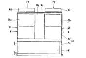
- FIG. 4 is an external front view of the composite binary refrigeration cycle apparatus shown in FIG. 3.
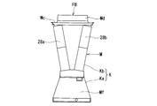
- the external appearance side view of the composite binary refrigerating-cycle apparatus shown in FIG. FIG. 4 is an external perspective view of a composite dual refrigeration cycle apparatus when an optional device is accommodated in the partition wall shown in FIG. 3.
- the external appearance perspective view which shows the state which removed the outer cover of the partition part of the composite binary refrigeration cycle apparatus shown in FIG.
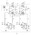
- FIG. 1 is a refrigeration cycle configuration diagram of a composite dual refrigeration cycle apparatus according to an embodiment used as a hot water supply system, for example.
- the composite binary refrigeration cycle apparatus has a first high-temperature side refrigeration in which, for example, R134a is circulated as a refrigerant in one housing K, hot water piping H that circulates water or hot water as a heat medium.
- the circuit R1a and the second high temperature side refrigeration circuit R1b, the first low temperature side refrigeration circuit R2a and the second low temperature side refrigeration circuit R2b that circulate, for example, R410A as a refrigerant, and the control device C are accommodated.
- the hot water pipe H has one end connected to a water supply source, a hot water storage tank, and the like, and the other end connected to a hot water storage side such as a hot water storage tank, a hot water tap.
- a pump 1 is connected to the hot water pipe H, and the water side flow path 3a of the first water / refrigerant heat exchanger 2A in the first high temperature side refrigeration circuit R1a with a predetermined interval on the downstream side thereof,
- the water side flow path 3b of the second water / refrigerant heat exchanger 2B in the second high temperature side refrigeration circuit R1b is connected.
- the first high temperature side refrigeration circuit R1a includes a discharge portion of the high temperature side compressor 5, the refrigerant side flow path 6 in the first water / heat exchanger 2A, the high temperature side receiver 7, the high temperature side expansion device 8, and the first.
- the high-temperature refrigerant flow path 10 of the cascade heat exchanger 9 and the suction part of the high-temperature side compressor 5 are sequentially connected by a refrigerant pipe P.
- the second high temperature side refrigeration circuit R1b includes a discharge portion of the high temperature side compressor 11, the refrigerant side flow path 12, the high temperature side receiver 13, the high temperature side expansion device 14, the second water / heat exchanger 2B.
- the high-temperature refrigerant flow path 16 of the cascade heat exchanger 15 and the suction portion of the high-temperature side compressor 11 are sequentially connected by the refrigerant pipe P.
- 1st low temperature side freezing circuit R2a has connected the discharge part of the low temperature side compressor 18 to the 1st port P1 of the four-way valve 19 through the refrigerant pipe P.
- the four-way valve 19 connects the second port P2 to the first low-temperature refrigerant flow path 33 of the second cascade heat exchanger 15, and the third port P3 is a first evaporator that is a first evaporator.
- the air heat exchanger 21 via refrigerant pipes P, respectively.
- the four-way valve 19 has its fourth port P4 connected to the suction portion of the low-temperature side compressor 18 through the accumulator 22 in series by the refrigerant pipe P.
- the first low-temperature refrigerant flow path 33 in the second cascade heat exchanger 15 is connected in series to the first low-temperature refrigerant flow path 20 in the first cascade heat exchanger 9 by the refrigerant pipe P. Further, the first low-temperature refrigerant flow path 20 in the first cascade heat exchanger 9 is sequentially connected to the low-temperature side receiver 23, the low-temperature side expansion device 24, and the air heat exchanger 21 by the refrigerant pipe P.
- a first blower fan FA is disposed opposite to the air heat exchanger 21.
- 2nd low temperature side freezing circuit R2b has connected the discharge part of the low temperature side compressor 25 to the 1st port P1 of the four-way valve 26 via the refrigerant pipe P.
- the four-way valve 26 connects the second port P2 to the second low-temperature refrigerant flow path 27 in the second cascade heat exchanger 15, and the third port P3 is a second evaporator that is a second evaporator.
- the air heat exchanger 28 via refrigerant pipes P, respectively.
- the four-way valve 26 has its fourth port connected to the suction portion of the low temperature side compressor 25 via the accumulator 29 in series by the refrigerant pipe P.
- the second low-temperature refrigerant flow path 27 in the second cascade heat exchanger 15 is connected in series to the second low-temperature refrigerant flow path 34 in the first cascade heat exchanger 9 by the refrigerant pipe P. .
- the second low-temperature refrigerant flow path 34 in the first cascade heat exchanger 9 is connected to the low-temperature side receiver 30, the low-temperature side expansion device 31, and the air heat exchanger 28 in the second low-temperature refrigeration circuit R 2 b.
- the pipes P are sequentially connected.
- a blower fan FB is disposed opposite to the air heat exchanger 28.
- FIG. 2 shows the configuration of the first cascade heat exchanger 9. Since the configuration of the first cascade heat exchanger 9 is the same as that of the second cascade heat exchanger 15, the latter description is omitted below.
- the first cascade heat exchanger 9 is provided on one side surface of the housing 40 at an end portion where the high-temperature refrigerant inlet 40a and the high-temperature refrigerant outlet 40b are separated from each other in the height direction.
- a refrigerant pipe P communicating with the high temperature side expansion device 8 is connected to the high temperature refrigerant introduction port 40a, and a refrigerant pipe P communicating with the suction portion of the high temperature side compressor 5 is connected to the high temperature refrigerant outlet port 40b.
- the housing 40 accommodates the high-temperature refrigerant flow path 10 therein.
- the high-temperature refrigerant flow path 10 is connected to the high-temperature refrigerant inlet 40a and the high-temperature refrigerant outlet 40b, and is paired with a pair of upper and lower main flow paths 41a and 41a parallel to each other and closed at opposite ends, and the main flow paths 41a, 41a, and a plurality of high-temperature refrigerant branch passages 41b parallel to each other at a predetermined interval in the horizontal direction in the figure.
- the housing 40 is provided with a first low-temperature refrigerant inlet 42a and a second low-temperature refrigerant inlet 43a on the other side surfaces at positions adjacent to each other. Furthermore, a first low-temperature refrigerant outlet 42 b and a second low-temperature refrigerant outlet 43 b are provided at positions adjacent to each other at positions separated on the same side surface of the housing 40.
- a refrigerant pipe P communicating with the first low-temperature refrigerant flow path 33 of the second cascade heat exchanger 15 is connected to the first low-temperature refrigerant inlet 42a, and the first low-temperature refrigerant outlet 42b is connected to the first low-temperature refrigerant outlet 42b.
- a refrigerant pipe P communicating with the low-temperature receiver 23 in the one low-temperature refrigeration circuit R2a is connected.
- a refrigerant pipe P communicating with the second low-temperature refrigerant flow path 27 of the second cascade heat exchanger 15 is connected to the second low-temperature refrigerant inlet 43a, and a second low-temperature refrigerant outlet 43b is connected to the second low-temperature refrigerant outlet 43b.
- a refrigerant pipe P communicating with the low-temperature receiver 30 in the second low-temperature refrigeration circuit R2b is connected.
- the housing 40 includes a first low-temperature refrigerant flow path 20 that communicates with the first low-temperature refrigerant inlet 42a and the first low-temperature refrigerant outlet 42b. Furthermore, a second low-temperature refrigerant flow path 34 communicating with the second low-temperature refrigerant inlet 43a and the second low-temperature refrigerant outlet 43b is formed in the housing 40.
- the first low-temperature refrigerant flow path 20 is connected to the first low-temperature refrigerant inlet port 42a and the first low-temperature refrigerant outlet port 42b, and is parallel to each other and closed at opposite ends in the figure. 44a, and a plurality of first low-temperature refrigerant branch flow paths 44b that communicate with each other between the pair of main flow paths 44a and 44a and are parallel to each other at a predetermined interval.
- the second low-temperature refrigerant channel 34 is connected to the second low-temperature refrigerant inlet 43a and the second low-temperature refrigerant outlet 43b, and is parallel to each other and closed between the main channel 45a and the main channel 45a. And a plurality of second low-temperature refrigerant branch flow paths 45b that are parallel to each other at a predetermined interval.
- the first low-temperature refrigerant branch channel 44 b that constitutes the first low-temperature refrigerant channel 20 and the second low-temperature refrigerant.
- the second low-temperature refrigerant branch flow paths 45b constituting the flow path 34 are provided in parallel at a predetermined interval.
- the first low-temperature refrigerant branch flow path 44b is provided on one surface side of the high-temperature refrigerant branch flow path 41b, and the second low-temperature refrigerant branch flow path 45b is provided on the other surface side.
- the two low-temperature refrigerant branch channels 44b and 45b are alternately arranged with respect to the high-temperature refrigerant branch channel 41b. For this reason, the flow of the high-temperature refrigerant and the low-temperature refrigerant becomes an opposite flow, and the heat transfer effect is improved.
- the flow path for the high-temperature refrigerant is provided inside the housing 40 and the low-temperature refrigerant flow path is formed on the outside thereof, the temperature drop of the high-temperature refrigerant can be reduced.
- the casing 40 constituting the first cascade heat exchanger 9 and the material of the partition member for partitioning each refrigerant flow path are made of materials having excellent thermal conductivity.
- the high-temperature refrigerant, the first low-temperature refrigerant, and the second low-temperature refrigerant efficiently exchange heat by the above-described flow path configuration of the first cascade heat exchanger 9 and selection of the constituent materials, thereby improving the heat exchange efficiency. be able to.
- the high-temperature refrigerant inlet 40a, the high-temperature refrigerant outlet 40b, the first low-temperature refrigerant inlet 42a, the second low-temperature refrigerant inlet 43a, the first low-temperature refrigerant outlet 42b, and the second low-temperature refrigerant outlet 43b are In addition to the above configuration, each of the side surfaces of the housing 40 may be provided, and there is no limitation.
- the high temperature refrigerant inlet 40a, the high temperature refrigerant outlet 40b, the first low temperature refrigerant inlet 42a, the second low temperature refrigerant inlet 43a, the first low temperature refrigerant outlet 42b, and the second low temperature refrigerant outlet 43b are: All may be provided on the same side surface of the housing 40.
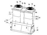
- FIGS. 3 to 5 are composite dual refrigeration cycle apparatus diagrams, FIG. 3 is an external perspective view of the composite dual refrigeration cycle apparatus according to the present embodiment, FIG. 4 is a front view thereof, and FIG. 5 is a side view thereof. is there.
- the composite binary refrigeration cycle apparatus has a housing K shown in FIG. 1 having an overall drum shape in a side view.
- the housing K includes a lower housing Ka having a substantially trapezoidal side surface and a substantially V-shaped upper housing Kb disposed integrally or integrally on the lower housing Ka.
- the upper housing Kb is composed of a plurality (here, two sets) of heat exchanger modules M and M and the same number of blower fans FA and FB.
- One set of heat exchanger modules M are arranged such that a pair (two) of air heat exchangers 21a and 21b, 28a and 28b face each other, and each of these air heat exchangers 21a and 21b, 28a and 28b. It is comprised by arrange
- Each heat exchanger module M is provided with a top plate Mc at its upper end, and the blower fans FA and FB are attached to the top plate Mc at positions facing each other between the heat exchanger modules M. Cylindrical air outlets Md and Md are projected above the top plate Mc, and the projecting end surfaces of the air outlets Md and Md are covered with fan guards Me and Me, respectively.
- the air heat exchangers 21a and 21b, and 28a and 28b constituting the heat exchanger module M are opposed to each other so that the top plate Mc side, which is the upper end portion, is wide and the lower housing Ka side is narrow and close to each other. Are inclined with respect to each other so as to be substantially V-shaped.
- a partition wall portion Mg is provided between the heat exchanger modules M and M so as not to affect the heat between the heat exchanger modules M and M.
- the lower housing Ka is configured in the machine room Mf.
- the machine room Mf includes refrigeration cycle components constituting the first and second high temperature side refrigeration circuits R1a and R1b and the first and second low temperature side refrigeration circuits R2a and R2b shown in FIG.
- the control device C is accommodated.
- the control device C has a function of controlling the entire operation of the composite binary refrigeration cycle device. For example, an ON / OFF control function for receiving ON / OFF control of the operation of the refrigeration cycle in response to an operation signal from an operation device such as an operation panel (not shown), a switching function of the operation mode (heating / defrosting operation mode) , The function of detecting frost formation of the second air heat exchangers 21 and 28, the function of controlling the refrigerant circulation flow rate by the opening degree control of the high-temperature side and low-temperature side expansion devices 8, 14, 24 and 31, first and second Of the high-temperature side compressors 5 and 11, the first and second low-temperature side compressors 18 and 25, and the first and second blower fans FA and FB per unit time (hereinafter simply referred to as the number of revolutions).
- an ON / OFF control function for receiving ON / OFF control of the operation of the refrigeration cycle in response to an operation signal from an operation device such as an operation panel (not shown), a switching function of the operation mode
- control device C includes the first and second high temperature side compressors 5 and 11, the first and second low temperature side compressors 18 and 25, and the first and second blower fans FA, Six inverter boards (not shown) for driving each of the FBs are stored.
- the four-way valves 19 and 26 of the first and second low temperature side refrigeration circuits R2a and R2b are in the heating operation mode.
- the opening degree of each expansion device 8, 14, 24, 31 is controlled to a predetermined opening degree.
- the compressors 5, 11, 18, 25 and the blower fans FA and FB are started and operated at a required rotational speed.
- the refrigerant is led to the first high temperature side refrigeration circuit R1a, the second high temperature side refrigeration circuit R1b, the first low temperature side refrigeration circuit R2a, and the second low temperature side refrigeration circuit R2b, and sequentially circulates. .
- the refrigerant R134a is converted into the high temperature side compressor 5—the refrigerant side flow path 6—the high temperature side receiver 7—the high temperature side expansion device 8 in the first water / refrigerant heat exchanger 2A.
- the high-temperature refrigerant flow path 10 in the first cascade heat exchanger 9-the high-temperature side compressor 5- are guided and circulated in this order.
- the refrigerant side flow path 6 in the first water / refrigerant heat exchanger 2A acts as a condenser, and the high temperature refrigerant flow path 10 in the first cascade heat exchanger 9 acts as an evaporator.
- the refrigerant R410A discharged from the low-temperature side compressor 18 is transferred to the first low-temperature refrigerant flow path 33-first cascade heat in the four-way valve 19-second cascade heat exchanger 15.
- the first low-temperature refrigerant flow path 20 the low-temperature side receiver 23, the low-temperature side expansion device 24, the first air heat exchanger 21, the four-way valve 19, the accumulator 22, and the low-temperature side compressor 18 are led and circulated in this order. To do.
- the refrigerant R134a is supplied from the high temperature side compressor 11—the refrigerant side flow path 12—the high temperature side receiver 13—the high temperature side expansion device 14—in the second water / refrigerant heat exchanger 2B.
- the high-temperature refrigerant flow path 16 and the high-temperature side compressor 11 are led in order and circulated.
- the refrigerant side flow path 12 in the second water / refrigerant heat exchanger 2B acts as a condenser, and the high temperature refrigerant flow path 16 in the second cascade heat exchanger 15 acts as an evaporator.
- the refrigerant R410A discharged from the low-temperature side compressor 25 is transferred to the second low-temperature refrigerant flow path 27-first cascade heat in the four-way valve 26-second cascade heat exchanger 15.
- the second low-temperature refrigerant flow path 34, the low-temperature side receiver 30, the low-temperature side expansion device 31, the second air heat exchanger 28, the four-way valve 26, the accumulator 29, and the low-temperature side compressor 25 are led and circulated in this order. To do.
- the first low-temperature refrigerant flow path 20 and the second low-temperature refrigerant flow path 34 act as a condenser, and as described above, the high-temperature refrigerant of the first high-temperature side refrigeration circuit R1a.
- the flow path 10 acts as an evaporator. That is, the refrigerant condenses in the first and second low-temperature refrigerant flow paths 20 and 34 to release condensation heat, and the condensation heat evaporates while absorbing heat in the high-temperature refrigerant flow path 10.
- the water or hot water led to the hot water pipe H through the pump 1 is condensed in the first high temperature side refrigeration circuit R1a in the water side flow path 3a of the first water / refrigerant heat exchanger 2A.
- High-temperature condensation heat is absorbed from the refrigerant-side flow path 6 of the water / refrigerant heat exchanger 2A, and rises to a high temperature.
- the hot water having a high temperature in the water side channel 3a of the first water / refrigerant heat exchanger 2A is guided to the water side channel 3b of the second water / refrigerant heat exchanger 2B.
- the first low-temperature refrigerant flow path 33 and the second low-temperature refrigerant flow path 27 act as a condenser, and as described above, the high-temperature refrigerant of the second high-temperature side refrigeration circuit R1b.
- the channel 16 acts as an evaporator. That is, the refrigerant condenses in the first and second low-temperature refrigerant flow paths 33 and 27 to release condensation heat, and the condensation heat evaporates while absorbing heat in the high-temperature refrigerant flow path 16.
- the hot water guided from the first water / refrigerant heat exchanger 2A to the water-side flow path 3b of the second water / refrigerant heat exchanger 2B is condensed into the first water by the second high-temperature side refrigeration circuit R1b.
- the high-temperature condensation heat is further absorbed from the refrigerant-side flow path 12 of the refrigerant heat exchanger 2B, and rises to a higher temperature. That is, the temperature rises to the set temperature in the water-side flow path 3b of the second water / refrigerant heat exchanger 2B.
- the hot water that has risen to the set temperature from the second water / refrigerant heat exchanger 2B is led to the hot water outlet such as a hot water storage tank or hot water tap. Then, it is led again to the first and second water / refrigerant heat exchangers 2A and 2B and heated and circulated to the hot water storage tank or discharged directly to the hot water tap.
- the controller C needs to switch the four-way valve 19 of the first low-temperature side refrigeration circuit R2b to the defrosting operation side and perform the defrosting operation of the first and second air heat exchangers 21 and 28. is there.
- the defrosting operation of the first and second air heat exchangers 21 and 28 is not performed simultaneously. For example, first, the defrosting operation of the first air heat exchanger 21 in the first low-temperature side refrigeration circuit R2a is performed. After the defrosting operation is completed, the defrosting operation of the second air heat exchanger 28 in the second low temperature side refrigeration circuit R2b is performed.
- the defrosting operation of the second air heat exchanger 28 may be performed first, and the defrosting operation of the first air heat exchanger 21 may be performed after the defrosting is completed.
- the control device C switches the four-way valve 19 of the first low temperature side refrigeration circuit R2a to the reverse cycle.
- the four-way valve 26 of the second low temperature side refrigeration circuit R2b is held in the heating operation.
- the operation of the compressor 5 of the first high temperature side refrigeration circuit R1a and the compressor 11 of the second high temperature side refrigeration circuit R1b is stopped by the control device C or is operated at a slow speed.
- the operating frequency of the compressor 25 of the second low temperature side refrigeration circuit R2b during the heating operation is based on the operating frequency of the compressors 18 and 25 when both the first and second low temperature side refrigeration circuits R2a and R2b are heated.
- the frequency is increased to a higher operating frequency.
- the rotation speed of the second blower fan FB is increased to the maximum rotation speed, the evaporation temperature is increased, and the capacity of the refrigeration cycle of the second low-temperature side refrigeration circuit R2b is increased.
- the pump 1 since the hot water is not heated, the pump 1 is stopped. However, the operation of the pump 1 may be continued when it is necessary to continuously circulate the hot water due to a request from the user side.
- the high-temperature and high-pressure refrigerant discharged from the low-temperature side compressor 18 is directly led to the first air heat exchanger 21 through the four-way valve 19 and condensed. The heat of condensation is released to melt the attached frost.
- the refrigerant evaporates in the first low-temperature refrigerant flow path 20 in the first cascade heat exchanger 9 and the first low-temperature refrigerant flow path 33 in the second cascade heat exchanger 15, but the second low-temperature refrigerant flow path Since the side refrigeration circuit R2b continues the heating operation, the amount of heat corresponding to the heat of evaporation is transferred to the second low-temperature refrigerant flow path 34 in the first cascade heat exchanger 9 and the second cascade heat exchanger. 15 continues to supply heat to the second low-temperature refrigerant flow path 27 in the form of condensation heat.
- the first cascade heat exchange is performed.
- the first low-temperature refrigerant flow path 20 and the second low-temperature refrigerant flow path 34 in the vessel 9 are not adjacent to each other, the protrusions formed on the plate of the heat exchanger are in metal contact with each other. Heat can be exchanged by heat conduction of the plate metal.
- the first low-temperature refrigerant flow path 33 and the second low-temperature refrigerant flow path 27 in the second cascade heat exchanger 15 can similarly conduct heat.
- the compressor 5 of the first high temperature side refrigeration circuit R1a and the compressor 11 of the second high temperature side refrigeration circuit R1b are operated at a low speed by heating operation during defrosting, the first The first low-temperature refrigerant flow path 10 between the first low-temperature refrigerant flow path 20 and the second low-temperature refrigerant flow path 34 in the cascade heat exchanger 9 and the first low-temperature refrigerant in the second cascade heat exchanger 15.
- the first low-temperature refrigerant flow paths 20 and 33 in the first low-temperature side refrigeration circuit R2a being defrosted are in the heating operation.
- the second low-temperature refrigerant circuit R2b in the second low-temperature side refrigeration circuit R2b absorbs heat from each of the second low-temperature refrigerant flow paths 34 and 27 to constitute a binary cycle during defrosting.
- the capacity of the compressor 25 of the second low-temperature refrigerant circuit R2b during the heating operation is increased and the second blower fan FB is operating at the maximum rotation speed, each second low-temperature refrigerant flow path 34, The amount of heat absorbed at 27 can be increased.
- the defrosting can be completed in a short time.
- warm water is not used as a heat source, an extreme temperature drop in the warm water in the warm water pipe H during defrosting can be prevented.
- the operation of the pump 1 since the operation of the pump 1 can be stopped, the outflow of unheated warm water can be prevented. However, the operation of the pump 1 may be continued when it is necessary to continuously circulate the hot water due to a request from the user side.
- the defrosting of the first air heat exchanger 21 When the defrosting of the first air heat exchanger 21 is completed, the process moves to the defrosting of the second air heat exchanger 28. That is, the four-way valve 19 of the first low-temperature side refrigeration circuit R2a is switched to the normal heating operation, and the four-way valve 26 of the second low-temperature side refrigeration circuit R2b is switched to the reverse cycle.
- the high temperature and high pressure refrigerant discharged from the low temperature side compressor 25 is directly led to the second air heat exchanger 28 via the four-way valve 26. It condenses and releases condensation heat to melt the attached frost.
- the refrigerant evaporates in the second low-temperature refrigerant flow path 34 in the first cascade heat exchanger 9 and the second low-temperature refrigerant flow path 27 in the second cascade heat exchanger 15, but the first low-temperature side refrigeration circuit Since R2a is in a heating operation, the amount of heat corresponding to the heat of evaporation is converted into the first low-temperature refrigerant flow path 20 in the first cascade heat exchanger 9 and the first amount in the second cascade heat exchanger 15. It continues to be supplied as condensation heat to the low-temperature refrigerant flow path 33.
- the second low-temperature refrigerant flow paths 34 and 27 in the second low-temperature side refrigeration circuit R2b being defrosted are in the heating operation. Heat is absorbed from the first low-temperature refrigerant flow paths 20 and 33 in the first low-temperature side refrigeration circuit R2a to constitute a two-way cycle during defrosting.
- the heat supply source is secured in this way, defrosting can be completed in a short time. Moreover, since warm water is not used as a heat source, an extreme temperature drop in the warm water in the warm water pipe H during defrosting can be prevented. Since the pump 1 can be stopped, the outflow of warm water that is not heated can be prevented. However, the operation of the pump 1 may be continued when it is necessary to continuously circulate the hot water due to a request from the user side.
- the four-way valve 26 of the second low temperature side refrigeration circuit R2b is switched to the normal heating operation, and the compressor 5 of the first high temperature side refrigeration circuit R1a is switched. If the compressor 11 of the second high temperature side refrigeration circuit R1b and the pump 1 are stopped, the pump 1 may be driven. Therefore, in the first and second high temperature side refrigeration circuits R1a and R1b, the four-way valve and the accumulator are not required, and the configuration can be simplified.
- defrosting can be completed in a short time.
- the temperature of the compressor is not lowered more than necessary, the capacity rises quickly when the heating operation is resumed after defrosting.
- the pump can be stopped at the time of defrosting, and it is possible to prevent warm water below the set temperature from flowing out.
- the compressors 18 and 25 of the other first and second low temperature side refrigeration circuits R2a and R2b that are heated are operated. Since the operating frequency is higher than the operating frequency when both the first and second low temperature side refrigeration circuits R2a and R2b are operated for heating, the first and second blower fans FA and FB are operating at the maximum rotational speed. The defrosting time can be shortened.
- the first and second air heat exchangers 21 and 28 (heat exchanger modules M and M) are separated from each other by the partition wall portion Mg, the first and second low-temperature side refrigeration circuits R2a and R2b During one defrosting operation, the other air heat exchangers 21 and 28 are not affected by heat and the defrosting time can be shortened.
- this empty space is a space that can appropriately accommodate a desired optional device such as a harmonic reduction device 60 described later, for example.
- the partition part Mg has the same structure by the front side and a back side, and demonstrates below by illustrating the front side.
- the partition wall portion Mg When accommodating the harmonic reduction device 60 in the partition wall portion Mg, the partition wall portion Mg is closed by an outer lid 50 in which a plurality of sheet metal air holes 50a are formed as shown in FIG.
- left and right partition plates 51 are provided to partition the partition wall portion Mg left and right at the left and right center in FIG. 7, and two harmonics are reduced in each of the chambers partitioned left and right as shown in FIG.
- the device 60 is arranged side by side in the vertical direction. That is, a total of four harmonic reduction devices 60a to 60d are accommodated in the partition wall portion Mg.
- the harmonic reduction devices 60a to 60d are, for example, 18-pulse rectifiers or 12-pulse rectifiers, and can be connected to the inverter boards for the compressors housed in the control device C to reduce harmonics.
- the harmonic reduction devices 60a to 60d are each provided with exhaust heat fans 61a to 61d for discharging the heat inside, and a plurality of ventilation holes (not shown) are formed on the side surfaces.
- the inner lids 52a to 52d are provided inside the partition wall portion Mg so as to hide the harmonic reduction devices 54a to 54d.
- a gap is provided between the inner lids 52a to 52d and the outer lid 50, and the air discharged from the harmonic reduction devices 60a to 60d is discharged from the vent hole 50a of the outer lid 50 to the outside of the partition wall portion Mg. Ventilation paths 53a to 53d are formed.
- the inner lids 52a to 53d are provided with fan holes 54a to 54d facing the exhaust heat fans 61a to 61d in a state where the harmonic reduction devices 60a to 60d are accommodated in the partition wall portion Mg.
- the air discharged from the heat exhaust fans 61a to 61d is discharged to the ventilation paths 53a to 53d through the fan holes 54a to 54d.
- Adjacent ventilation paths 53 a and 53 b (back side 53 c and 53 d) are partitioned by a left and right partition plate 51. That is, four independent ventilation paths 53a to 53d are formed.
- the harmonic reduction device 60a arranged at the upper left stage is connected to the inverter board for the low temperature compressor 18 of the low temperature side refrigeration circuit R2a, and the harmonic reduction device 60b arranged at the lower right stage is the high temperature side refrigeration. It is connected to the inverter board for the high temperature side compressor 5 of the circuit R1a.
- the harmonic reduction device 60c disposed in the upper right stage is connected to the inverter board for the low temperature side compressor 25 of the low temperature side refrigeration circuit R2b, and the harmonic reduction device 60d disposed in the lower left stage is the high temperature side refrigeration circuit R1b. It is connected to the inverter board for the high temperature side compressor 11.
- the respective harmonic reduction devices 60a to 60d are arranged corresponding to the four independent ventilation paths 53a to 53d, so that they are not affected by the exhaust heat of the other harmonic reduction devices. .
- harmonic reduction device 60 is incorporated as necessary, and may be incorporated in up to four units or may not be incorporated in one unit.
- the harmonic reduction device 60 can be selectively disposed on the inverter board as necessary.
Landscapes
- Engineering & Computer Science (AREA)
- Physics & Mathematics (AREA)
- Mechanical Engineering (AREA)
- Thermal Sciences (AREA)
- General Engineering & Computer Science (AREA)
- Heat-Pump Type And Storage Water Heaters (AREA)
- Devices That Are Associated With Refrigeration Equipment (AREA)
Abstract
Provided is a composite dual refrigeration cycle device provided with: two high-temperature side refrigeration circuits respectively having water/refrigerant heat exchangers for heat exchange of water and a refrigerant discharged from a compressor on the high-temperature side, and two low-temperature side refrigeration circuits respectively having evaporators comprising air heat exchangers having blower fans, the circuits being built into the same chassis; and with hot water lines configured to permit heat exchange from the respective high-temperature side refrigeration circuits to the respective low-temperature side refrigeration circuits by a cascade heat exchanger, for circulating cold water or hot water to the cold water-side flow channel of the water/refrigerant heat exchangers of the high-temperature side refrigeration circuits, the interior of the chassis being furnished with a control device for overall control of operation of the device. The composite dual refrigeration cycle device is characterized in that the device is configured such that the two low-temperature side refrigeration circuits are connected to the control device, and when one of the low-temperature side refrigeration circuits performs a defrosting operation of the evaporator thereof, the other low-temperature side refrigeration circuit is controlled so as to perform heat exchange with the cascade heat exchanger, while the rotation speed of the blower fan of the other low-temperature side refrigeration circuit is controlled to a rotation speed higher than the rotation speed of the blower fan during a heating operation of both of the low-temperature side refrigeration circuits together.
Description
本発明は、二元冷凍サイクルを2系統並設した場合の複合二元冷凍サイクル装置に関する。
The present invention relates to a composite binary refrigeration cycle apparatus when two binary refrigeration cycles are juxtaposed.
従来この種の二元冷凍サイクル装置としては、温水配管を流れる水または温水を加熱する高温側冷凍回路に、この高温側冷凍回路を循環する高温側冷媒を加熱する低温側冷凍回路をカスケード熱交換器を介して熱交換可能に接続することにより二元冷凍サイクルを構成し、1つの筐体に収容したものが知られている(例えば、特許文献1参照)。
Conventionally, as this type of dual refrigeration cycle apparatus, cascade heat exchange is performed between a high-temperature side refrigeration circuit that heats water flowing through a hot-water pipe or hot water, and a low-temperature side refrigeration circuit that heats a high-temperature side refrigerant circulating in the high-temperature side refrigeration circuit It is known that a two-stage refrigeration cycle is configured by connecting in a heat exchangeable manner through a container and accommodated in one housing (see, for example, Patent Document 1).
近年は、より高効率に温水を加温するために、2つの二元冷凍サイクル装置を温水配管に対して直列または並列に接続した複合二元冷凍サイクル装置が提供されようとしている。
In recent years, in order to warm hot water with higher efficiency, a composite binary refrigeration cycle apparatus in which two binary refrigeration cycle apparatuses are connected in series or in parallel to a hot water pipe is being provided.
この複合二元冷凍サイクル装置では、低温側冷凍回路に蒸発器として空気熱交換器が用いられており、ここに導かれた冷媒は外気と熱交換して蒸発する。そのため、外気温が極低温になると外気に含まれる水分が凍結して霜になり、そのまま付着する。
In this composite binary refrigeration cycle apparatus, an air heat exchanger is used as an evaporator in the low temperature side refrigeration circuit, and the refrigerant introduced here evaporates by exchanging heat with the outside air. For this reason, when the outside air temperature becomes extremely low, the moisture contained in the outside air freezes to become frost and adheres as it is.
空気熱交換器が着霜すると熱交換効率が低下するので、除霜が必要となる。このための除霜方式としては、高温側冷媒回路および低温側冷凍回路のそれぞれの四方弁を切り換えて冷媒の循環方向を逆転させる逆サイクル除霜方式や、低温側冷凍回路の圧縮機の高温吐出冷媒を、カスケード熱交換器をバイパスさせて、直接蒸発器に導くホットガス除霜方式が考えられる。
¡Defrosting is necessary because the heat exchange efficiency decreases when the air heat exchanger is frosted. For this purpose, the defrosting method includes a reverse cycle defrosting method in which the four-way valves of the high-temperature side refrigerant circuit and the low-temperature side refrigeration circuit are switched to reverse the refrigerant circulation direction, or the high-temperature discharge of the compressor of the low-temperature side refrigeration circuit A hot gas defrosting system in which the refrigerant is bypassed through the cascade heat exchanger and directly led to the evaporator can be considered.
しかし、逆サイクル除霜方式の場合には、利用側の温水を熱源とするために短時間で除霜を完了できるメリットはあるものの、温水出口温度を入口温度よりも低下させてしまうという不具合がある。また、ホットガス除霜方式の場合には、上術の逆サイクル除霜方式における不具合は生じないものの、除霜に必要な熱源に乏しいために除霜時間の増大を招き、結果として温水を加温できない時間が増加する不具合がある。
However, in the case of the reverse cycle defrosting method, there is a merit that the defrosting can be completed in a short time because hot water on the use side is used as a heat source, but there is a problem that the hot water outlet temperature is lower than the inlet temperature. is there. In addition, in the case of the hot gas defrosting method, there are no problems with the reverse cycle defrosting method of the above operation, but because the heat source necessary for defrosting is insufficient, the defrosting time is increased and hot water is added as a result. There is a problem that the time that cannot be heated increases.
従って、本発明の目的は、上述の従来技術の課題を鑑み、2つの二元冷凍サイクルを備えていても、構成の簡素化を維持できると共に、温水配管を流れる水または温水の温度をできるだけ下げずに給湯し、しかも、短時間で除霜できる複合二元冷凍サイクル装置を提供することにある。
Therefore, in view of the above-described problems of the prior art, the object of the present invention is to maintain the simplification of the configuration even if two binary refrigeration cycles are provided, and to reduce the temperature of water flowing through the hot water piping or hot water as much as possible. An object of the present invention is to provide a composite dual refrigeration cycle apparatus that can supply hot water without defrosting in a short time.
上記目的を達成するために提供される本発明の一実施態様である複合二元冷凍サイクル装置は、高温側圧縮機から吐出された冷媒を水と熱交換する水・冷媒熱交換器をそれぞれ有する二つの高温側冷凍回路と、送風ファンを有する空気熱交換器からなる蒸発器をそれぞれ有する二つの低温側冷凍回路とを同一筐体に搭載すると共に、上記それぞれの高温側冷凍回路がカスケード熱交換器により上記二つの低温側冷凍回路のそれぞれと熱交換可能に構成され、上記高温側冷凍回路の水・冷媒熱交換器の水側流路に水または温水を流通させる温水配管を備え、上記筐体内には装置の運転全体を制御する制御装置が設けられた、複合二元冷凍サイクル装置であって、上記二つの低温側冷凍回路は、上記制御装置に接続され、一方の低温側冷凍回路がその蒸発器の除霜運転を行うとき、他方の低温側冷凍回路を、上記カスケード熱交換器で放熱を行うように制御すると共に、他方の低温側冷凍回路の送風ファンの回転数を、両方の低温側冷凍回路を共に加熱運転するときの送風ファンの回転数よりも高い回転数に制御するように構成されていることを特徴とする。
The composite dual refrigeration cycle apparatus that is one embodiment of the present invention provided to achieve the above object includes a water / refrigerant heat exchanger that exchanges heat between the refrigerant discharged from the high-temperature side compressor and water. Two high temperature side refrigeration circuits and two low temperature side refrigeration circuits each having an evaporator composed of an air heat exchanger having a blower fan are mounted in the same housing, and each of the high temperature side refrigeration circuits is cascade heat exchange. And a hot water pipe configured to circulate water or hot water in the water-side flow path of the water / refrigerant heat exchanger of the high-temperature side refrigeration circuit. A composite dual refrigeration cycle apparatus provided with a control device for controlling the overall operation of the apparatus in the body, wherein the two low temperature side refrigeration circuits are connected to the control device, and one of the low temperature side refrigeration circuits When performing the defrosting operation of the evaporator, the other low-temperature side refrigeration circuit is controlled to radiate heat by the cascade heat exchanger, and the rotation speed of the blower fan of the other low-temperature side refrigeration circuit is adjusted to both It is configured to control the rotational speed to be higher than the rotational speed of the blower fan when the low temperature side refrigeration circuit is heated together.
また、上記複合二元冷凍サイクル装置において、上記各カスケード熱交換器は、高温側冷凍回路に連通する高温冷媒流路と、一方の低温側冷凍回路に連通する第1の低温冷媒流路と、他方の低温側冷凍回路に連通する第2の低温冷媒流路を備えると共に、前記第1の低温冷媒流路同士と、前記第2の冷媒流路同士をそれぞれ直列に接続し、上記高温冷媒流路の一面側に第1の低温冷媒流路を配置し、他面側に第2の低温冷媒流路を配置したプレート式熱交換器により構成するようにする事が好ましい。
Further, in the composite binary refrigeration cycle apparatus, each of the cascade heat exchangers includes a high-temperature refrigerant channel communicating with the high-temperature side refrigeration circuit, a first low-temperature refrigerant channel communicating with one of the low-temperature side refrigeration circuits, A second low-temperature refrigerant flow path communicating with the other low-temperature side refrigeration circuit is provided, the first low-temperature refrigerant flow paths and the second refrigerant flow paths are connected in series, respectively, and the high-temperature refrigerant flow It is preferable that the first low-temperature refrigerant flow path is disposed on one surface side of the path and the plate-type heat exchanger is disposed on the other surface side with the second low-temperature refrigerant flow path.
上記特徴を有する本発明の実施例によれば、上述の従来技術の課題を解決すると共に、2つの二元冷凍サイクルを備えていても、構成の簡素化を維持できると共に、温水配管を流れる水または温水の温度をできるだけ下げずに給湯し、しかも、短時間で除霜できる複合二元冷凍サイクル装置を提供することができる。さらに詳細な効果については、本明細書末尾まとめて記載する。
According to the embodiment of the present invention having the above-described features, the problem of the above-described prior art can be solved, and even if two binary refrigeration cycles are provided, the simplification of the configuration can be maintained and the water flowing through the hot water pipe can be maintained. Alternatively, it is possible to provide a combined dual refrigeration cycle apparatus that can supply hot water without lowering the temperature of hot water as much as possible and defrost in a short time. Further detailed effects are described collectively at the end of this specification.
以下、本実施形態を図面に基づいて説明する。なお、複数の図面中、同一または相当部分には同一符号を付している。
Hereinafter, the present embodiment will be described with reference to the drawings. In addition, the same code | symbol is attached | subjected to the same or an equivalent part in several drawing.
図1は、例えば給湯システムとして用いられる一実施形態に係る複合二元冷凍サイクル装置の冷凍サイクル構成図である。
FIG. 1 is a refrigeration cycle configuration diagram of a composite dual refrigeration cycle apparatus according to an embodiment used as a hot water supply system, for example.
図1に示すように、複合二元冷凍サイクル装置は、1つの筐体K内に、熱媒体である水または温水を流通する温水配管H、冷媒として例えばR134aを循環させる第1の高温側冷凍回路R1aおよび第2の高温側冷凍回路R1b、冷媒として例えばR410Aを循環させる第1の低温側冷凍回路R2aおよび第2の低温側冷凍回路R2bと、制御装置Cを収容する。
As shown in FIG. 1, the composite binary refrigeration cycle apparatus has a first high-temperature side refrigeration in which, for example, R134a is circulated as a refrigerant in one housing K, hot water piping H that circulates water or hot water as a heat medium. The circuit R1a and the second high temperature side refrigeration circuit R1b, the first low temperature side refrigeration circuit R2a and the second low temperature side refrigeration circuit R2b that circulate, for example, R410A as a refrigerant, and the control device C are accommodated.
温水配管Hは、一端側を給水源、貯湯タンクなどに接続し、他端側は貯湯タンク、給湯栓などの出湯側に接続される。
The hot water pipe H has one end connected to a water supply source, a hot water storage tank, and the like, and the other end connected to a hot water storage side such as a hot water storage tank, a hot water tap.
温水配管Hにはポンプ1が接続されると共に、この下流側に所定間隔を置いて第1の高温側冷凍回路R1aにおける第1の水・冷媒熱交換器2Aの水側流路3aと、第2の高温側冷凍回路R1bにおける第2の水・冷媒熱交換器2Bの水側流路3bとが接続される。
A pump 1 is connected to the hot water pipe H, and the water side flow path 3a of the first water / refrigerant heat exchanger 2A in the first high temperature side refrigeration circuit R1a with a predetermined interval on the downstream side thereof, The water side flow path 3b of the second water / refrigerant heat exchanger 2B in the second high temperature side refrigeration circuit R1b is connected.
上記第1の高温側冷凍回路R1aは、高温側圧縮機5の吐出部、上記第1の水・熱交換器2Aにおける冷媒側流路6、高温側レシーバ7、高温側膨張装置8、第1のカスケード熱交換器9の高温冷媒流路10および上記高温側圧縮機5の吸込み部を、冷媒管Pにより順次、接続している。
The first high temperature side refrigeration circuit R1a includes a discharge portion of the high temperature side compressor 5, the refrigerant side flow path 6 in the first water / heat exchanger 2A, the high temperature side receiver 7, the high temperature side expansion device 8, and the first. The high-temperature refrigerant flow path 10 of the cascade heat exchanger 9 and the suction part of the high-temperature side compressor 5 are sequentially connected by a refrigerant pipe P.
第2の高温側冷凍回路R1bは、高温側圧縮機11の吐出部、上記第2の水・熱交換器2Bにおける冷媒側流路12、高温側レシーバ13、高温側膨張装置14、第2のカスケード熱交換器15の高温冷媒流路16および上記高温側圧縮機11の吸込み部を、冷媒管Pにより順次、接続している。
The second high temperature side refrigeration circuit R1b includes a discharge portion of the high temperature side compressor 11, the refrigerant side flow path 12, the high temperature side receiver 13, the high temperature side expansion device 14, the second water / heat exchanger 2B. The high-temperature refrigerant flow path 16 of the cascade heat exchanger 15 and the suction portion of the high-temperature side compressor 11 are sequentially connected by the refrigerant pipe P.
第1の低温側冷凍回路R2aは、低温側圧縮機18の吐出部を、四方弁19の第1のポートP1に、冷媒管Pを介して接続している。四方弁19は、その第2のポートP2を、第2のカスケード熱交換器15の第1の低温冷媒流路33に接続し、第3のポートP3を、第1の蒸発器である第1の空気熱交換器21に、それぞれ冷媒管Pを介して接続している。
1st low temperature side freezing circuit R2a has connected the discharge part of the low temperature side compressor 18 to the 1st port P1 of the four-way valve 19 through the refrigerant pipe P. As shown in FIG. The four-way valve 19 connects the second port P2 to the first low-temperature refrigerant flow path 33 of the second cascade heat exchanger 15, and the third port P3 is a first evaporator that is a first evaporator. Are connected to the air heat exchanger 21 via refrigerant pipes P, respectively.
また、四方弁19は、その第4のポートP4を、アキュームレータ22を介して低温側圧縮機18の吸込み部に直列に冷媒管Pにより接続している。
Further, the four-way valve 19 has its fourth port P4 connected to the suction portion of the low-temperature side compressor 18 through the accumulator 22 in series by the refrigerant pipe P.
そして、第2のカスケード熱交換器15における第1の低温冷媒流路33は、第1のカスケード熱交換器9における第1の低温冷媒流路20に、冷媒管Pにより直列に接続される。さらに、この第1のカスケード熱交換器9における第1の低温冷媒流路20は、低温側レシーバ23、低温側膨張装置24および空気熱交換器21に冷媒管Pにより順次接続される。この空気熱交換器21には、第1の送風ファンFAが対向配置される。
The first low-temperature refrigerant flow path 33 in the second cascade heat exchanger 15 is connected in series to the first low-temperature refrigerant flow path 20 in the first cascade heat exchanger 9 by the refrigerant pipe P. Further, the first low-temperature refrigerant flow path 20 in the first cascade heat exchanger 9 is sequentially connected to the low-temperature side receiver 23, the low-temperature side expansion device 24, and the air heat exchanger 21 by the refrigerant pipe P. A first blower fan FA is disposed opposite to the air heat exchanger 21.
第2の低温側冷凍回路R2bは、低温側圧縮機25の吐出部を、四方弁26の第1のポートP1に、冷媒管Pを介して接続している。四方弁26は、その第2のポートP2を、第2のカスケード熱交換器15における第2の低温冷媒流路27に接続し、第3のポートP3を、第2の蒸発器である第2の空気熱交換器28に、それぞれ冷媒管Pを介して接続している。
2nd low temperature side freezing circuit R2b has connected the discharge part of the low temperature side compressor 25 to the 1st port P1 of the four-way valve 26 via the refrigerant pipe P. As shown in FIG. The four-way valve 26 connects the second port P2 to the second low-temperature refrigerant flow path 27 in the second cascade heat exchanger 15, and the third port P3 is a second evaporator that is a second evaporator. Are connected to the air heat exchanger 28 via refrigerant pipes P, respectively.
また、四方弁26は、その第4のポートを、アキュームレータ29を介して低温側圧縮機25の吸込み部に直列に冷媒管Pにより接続している。
Further, the four-way valve 26 has its fourth port connected to the suction portion of the low temperature side compressor 25 via the accumulator 29 in series by the refrigerant pipe P.
そして、上記第2のカスケード熱交換器15における第2の低温冷媒流路27は、第1のカスケード熱交換器9における第2の低温冷媒流路34に、冷媒管Pにより直列に接続される。
The second low-temperature refrigerant flow path 27 in the second cascade heat exchanger 15 is connected in series to the second low-temperature refrigerant flow path 34 in the first cascade heat exchanger 9 by the refrigerant pipe P. .
さらに、この第1のカスケード熱交換器9における第2の低温冷媒流路34は、第2の低温冷凍回路R2bにおける低温側レシーバ30、低温側膨張装置31および上記空気熱交換器28に、冷媒管Pにより順次接続される。この空気熱交換器28には、送風ファンFBが対向配置される。
Further, the second low-temperature refrigerant flow path 34 in the first cascade heat exchanger 9 is connected to the low-temperature side receiver 30, the low-temperature side expansion device 31, and the air heat exchanger 28 in the second low-temperature refrigeration circuit R 2 b. The pipes P are sequentially connected. A blower fan FB is disposed opposite to the air heat exchanger 28.
図2は、上記第1のカスケード熱交換器9の構成を示す。この第1のカスケード熱交換器9の構成は、第2のカスケード熱交換器15の構成と同じであるので、以下、後者の説明は省略する。
FIG. 2 shows the configuration of the first cascade heat exchanger 9. Since the configuration of the first cascade heat exchanger 9 is the same as that of the second cascade heat exchanger 15, the latter description is omitted below.
第1のカスケード熱交換器9は、その筐体40の一側面に、高温冷媒導入口40aと高温冷媒導出口40bが高さ方向で互いに離間した端部に設けられる。高温冷媒導入口40aには高温側膨張装置8に連通する冷媒管Pが接続され、高温冷媒導出口40bには高温側圧縮機5の吸込み部に連通する冷媒管Pが接続される。
The first cascade heat exchanger 9 is provided on one side surface of the housing 40 at an end portion where the high-temperature refrigerant inlet 40a and the high-temperature refrigerant outlet 40b are separated from each other in the height direction. A refrigerant pipe P communicating with the high temperature side expansion device 8 is connected to the high temperature refrigerant introduction port 40a, and a refrigerant pipe P communicating with the suction portion of the high temperature side compressor 5 is connected to the high temperature refrigerant outlet port 40b.
筐体40は、その内部に、高温冷媒流路10を収容している。この高温冷媒流路10は、高温冷媒導入口40aと高温冷媒導出口40bに接続され、互いに平行で対向端部が閉塞される図中上下一対の主流路41a、41aと、これら主流路41a、41a間に亘って連通され、図中横方向に互いに所定間隔を置いて平行な複数の高温冷媒分岐流路41bとを有する。
The housing 40 accommodates the high-temperature refrigerant flow path 10 therein. The high-temperature refrigerant flow path 10 is connected to the high-temperature refrigerant inlet 40a and the high-temperature refrigerant outlet 40b, and is paired with a pair of upper and lower main flow paths 41a and 41a parallel to each other and closed at opposite ends, and the main flow paths 41a, 41a, and a plurality of high-temperature refrigerant branch passages 41b parallel to each other at a predetermined interval in the horizontal direction in the figure.
筐体40は、その他側面に、第1の低温冷媒導入口42aと、第2の低温冷媒導入口43aとを、互いに隣接した位置に設けている。さらに、筐体40の同じ側面で離間した位置には、第1の低温冷媒導出口42bと、第2の低温冷媒導出口43bとが、互いに隣接した位置に設けられる。
The housing 40 is provided with a first low-temperature refrigerant inlet 42a and a second low-temperature refrigerant inlet 43a on the other side surfaces at positions adjacent to each other. Furthermore, a first low-temperature refrigerant outlet 42 b and a second low-temperature refrigerant outlet 43 b are provided at positions adjacent to each other at positions separated on the same side surface of the housing 40.
第1の低温冷媒導入口42aには、第2のカスケード熱交換器15の第1の低温冷媒流路33に連通する冷媒管Pが接続され、第1の低温冷媒導出口42bには、第1の低温冷凍回路R2aにおける低温側レシーバ23と連通する冷媒管Pが接続される。
A refrigerant pipe P communicating with the first low-temperature refrigerant flow path 33 of the second cascade heat exchanger 15 is connected to the first low-temperature refrigerant inlet 42a, and the first low-temperature refrigerant outlet 42b is connected to the first low-temperature refrigerant outlet 42b. A refrigerant pipe P communicating with the low-temperature receiver 23 in the one low-temperature refrigeration circuit R2a is connected.
第2の低温冷媒導入口43aには、第2のカスケード熱交換器15の第2の低温冷媒流路27に連通する冷媒管Pが接続され、第2の低温冷媒導出口43bには、第2の低温冷凍回路R2bにおける低温側レシーバ30と連通する冷媒管Pが接続される。
A refrigerant pipe P communicating with the second low-temperature refrigerant flow path 27 of the second cascade heat exchanger 15 is connected to the second low-temperature refrigerant inlet 43a, and a second low-temperature refrigerant outlet 43b is connected to the second low-temperature refrigerant outlet 43b. A refrigerant pipe P communicating with the low-temperature receiver 30 in the second low-temperature refrigeration circuit R2b is connected.
筐体40は、その内部に、第1の低温冷媒導入口42aと第1の低温冷媒導出口42bに連通する、第1の低温冷媒流路20を構成している。さらに、筐体40内には、第2の低温冷媒導入口43aと第2の低温冷媒導出口43bに連通する、第2の低温冷媒流路34が構成される。
The housing 40 includes a first low-temperature refrigerant flow path 20 that communicates with the first low-temperature refrigerant inlet 42a and the first low-temperature refrigerant outlet 42b. Furthermore, a second low-temperature refrigerant flow path 34 communicating with the second low-temperature refrigerant inlet 43a and the second low-temperature refrigerant outlet 43b is formed in the housing 40.
第1の低温冷媒流路20は、第1の低温冷媒導入口42aと第1の低温冷媒導出口42bに接続して互いに平行で対向端部が閉塞される図中上下一対の主流路44a、44aと、これら一対の主流路44a、44a間に亘って連通され、互いに所定間隔を置いて平行な複数の第1の低温冷媒分岐流路44bを有する。
The first low-temperature refrigerant flow path 20 is connected to the first low-temperature refrigerant inlet port 42a and the first low-temperature refrigerant outlet port 42b, and is parallel to each other and closed at opposite ends in the figure. 44a, and a plurality of first low-temperature refrigerant branch flow paths 44b that communicate with each other between the pair of main flow paths 44a and 44a and are parallel to each other at a predetermined interval.
第2の低温冷媒流路34は、第2の低温冷媒導入口43aと第2の低温冷媒導出口43bに接続して互いに平行で端部が閉塞される主流路45aと、これら主流路45a間に亘って連通され、互いに所定間隔を置いて平行な複数の第2の低温冷媒分岐流路45bとからなる。
The second low-temperature refrigerant channel 34 is connected to the second low-temperature refrigerant inlet 43a and the second low-temperature refrigerant outlet 43b, and is parallel to each other and closed between the main channel 45a and the main channel 45a. And a plurality of second low-temperature refrigerant branch flow paths 45b that are parallel to each other at a predetermined interval.
すなわち、筐体40内において、高温冷媒流路10を構成する高温冷媒分岐流路41bと、第1の低温冷媒流路20を構成する第1の低温冷媒分岐流路44bおよび第2の低温冷媒流路34を構成する第2の低温冷媒分岐流路45bは、互いに所定間隔を置いて平行に設けられる。
That is, in the housing 40, the high-temperature refrigerant branch channel 41 b that constitutes the high-temperature refrigerant channel 10, the first low-temperature refrigerant branch channel 44 b that constitutes the first low-temperature refrigerant channel 20, and the second low-temperature refrigerant. The second low-temperature refrigerant branch flow paths 45b constituting the flow path 34 are provided in parallel at a predetermined interval.
つまり、高温冷媒分岐流路41bを挟んで、その一面側に第1の低温冷媒分岐流路44bを設け、その他面側に第2の低温冷媒分岐流路45bを設けることにより、第1、第2の低温冷媒分岐流路44b、45bを高温冷媒分岐流路41bに対して交互に配置している。このために、高温冷媒と低温冷媒の流れが対向流となり、熱伝達効果が向上する。しかも、高温冷媒の流路を筐体40内の内側に設け、その外側に低温冷媒流路を形成しているので、高温冷媒の降温の低減を図ることができる。
In other words, the first low-temperature refrigerant branch flow path 44b is provided on one surface side of the high-temperature refrigerant branch flow path 41b, and the second low-temperature refrigerant branch flow path 45b is provided on the other surface side. The two low-temperature refrigerant branch channels 44b and 45b are alternately arranged with respect to the high-temperature refrigerant branch channel 41b. For this reason, the flow of the high-temperature refrigerant and the low-temperature refrigerant becomes an opposite flow, and the heat transfer effect is improved. In addition, since the flow path for the high-temperature refrigerant is provided inside the housing 40 and the low-temperature refrigerant flow path is formed on the outside thereof, the temperature drop of the high-temperature refrigerant can be reduced.
また、第1のカスケード熱交換器9を構成する筐体40と、各冷媒流路を仕切る仕切部材の素材は、熱伝導性に優れたものが用いられている。第1のカスケード熱交換器9の上記の流路構成と、構成素材の選択により、高温冷媒と第1の低温冷媒および第2の低温冷媒は効率良く熱交換し、熱交換効率の向上を図ることができる。
Further, the casing 40 constituting the first cascade heat exchanger 9 and the material of the partition member for partitioning each refrigerant flow path are made of materials having excellent thermal conductivity. The high-temperature refrigerant, the first low-temperature refrigerant, and the second low-temperature refrigerant efficiently exchange heat by the above-described flow path configuration of the first cascade heat exchanger 9 and selection of the constituent materials, thereby improving the heat exchange efficiency. be able to.
なお、高温冷媒導入口40a、高温冷媒導出口40b、第1の低温冷媒導入口42a、第2の低温冷媒導入口43a、第1の低温冷媒導出口42bおよび第2の低温冷媒導出口43bは、上記構成に限らず、それぞれ筐体40のいずれの側面に設けても良く、何等制限はない。
The high-temperature refrigerant inlet 40a, the high-temperature refrigerant outlet 40b, the first low-temperature refrigerant inlet 42a, the second low-temperature refrigerant inlet 43a, the first low-temperature refrigerant outlet 42b, and the second low-temperature refrigerant outlet 43b are In addition to the above configuration, each of the side surfaces of the housing 40 may be provided, and there is no limitation.
例えば、高温冷媒導入口40a、高温冷媒導出口40b、第1の低温冷媒導入口42a、第2の低温冷媒導入口43a、第1の低温冷媒導出口42bおよび第2の低温冷媒導出口43bは、全て筐体40の同一の側面に設けても良い。
For example, the high temperature refrigerant inlet 40a, the high temperature refrigerant outlet 40b, the first low temperature refrigerant inlet 42a, the second low temperature refrigerant inlet 43a, the first low temperature refrigerant outlet 42b, and the second low temperature refrigerant outlet 43b are: All may be provided on the same side surface of the housing 40.
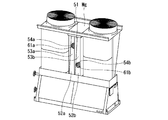
図3~図5は複合二元冷凍サイクル装置図を示し、図3は、本実施形態に係る複合二元冷凍サイクル装置の外観斜視図、図4は同正面図、図5は同側面図である。これら図3~図5に示すように複合二元冷凍サイクル装置は、全体形状が側面視でほぼ鼓形の上記図1で示す筐体Kを有する。筐体Kは、側面形状がほぼ台形状の下部筐体Kaと、この下部筐体Ka上に一体または一体的に配置されるほぼV字状の上部筐体Kbとを具備している。
FIGS. 3 to 5 are composite dual refrigeration cycle apparatus diagrams, FIG. 3 is an external perspective view of the composite dual refrigeration cycle apparatus according to the present embodiment, FIG. 4 is a front view thereof, and FIG. 5 is a side view thereof. is there. As shown in FIGS. 3 to 5, the composite binary refrigeration cycle apparatus has a housing K shown in FIG. 1 having an overall drum shape in a side view. The housing K includes a lower housing Ka having a substantially trapezoidal side surface and a substantially V-shaped upper housing Kb disposed integrally or integrally on the lower housing Ka.
上部筐体Kbは、複数(ここでは2組)の熱交換器モジュールM、Mと、同数の送風ファンFA、FBから構成される。1組の熱交換器モジュールMは、一対(2個)の空気熱交換器21aと21b、28aと28bをそれぞれ互いに対向させて配置し、これら空気熱交換器21aと21b、28aと28bの各上端部相互間の空間部に送風ファンFA、FBを配置することにより構成されている。
The upper housing Kb is composed of a plurality (here, two sets) of heat exchanger modules M and M and the same number of blower fans FA and FB. One set of heat exchanger modules M are arranged such that a pair (two) of air heat exchangers 21a and 21b, 28a and 28b face each other, and each of these air heat exchangers 21a and 21b, 28a and 28b. It is comprised by arrange | positioning ventilation fan FA and FB in the space part between upper end parts.
各熱交換器モジュールMは、その上端部に天板Mcを設け、この天板Mcの熱交換器モジュールM相互間に対向する位置に上記送風ファンFA、FBを取り付けている。天板Mcから上方には円筒状の吹出口Md、Mdを突設し、これら吹出口Md、Mdの突出端面をファンガードMe、Meによりそれぞれ覆っている。
Each heat exchanger module M is provided with a top plate Mc at its upper end, and the blower fans FA and FB are attached to the top plate Mc at positions facing each other between the heat exchanger modules M. Cylindrical air outlets Md and Md are projected above the top plate Mc, and the projecting end surfaces of the air outlets Md and Md are covered with fan guards Me and Me, respectively.
上記熱交換器モジュールMを構成する空気熱交換器21aと21b、及び28aと28bは相互ともに上端部である天板Mc側が広く、下部筐体Ka側が狭く近接するよう対向していて、側面視で略V字状になるよう互いに傾斜している。また、熱交換器モジュールM、Mの間には、隔壁部Mgが設けられ、熱交換器モジュールM、M相互間で熱影響を及ぼさないようになっている。下部筐体Kaは機械室Mfに構成されている。機械室Mfは、その内部に、図1で示す第1、第2の高温側冷凍回路R1a、R1bおよび第1、第2の低温側冷凍回路R2a、R2bをそれぞれ構成する冷凍サイクル構成部品と、制御装置Cを収容している。
The air heat exchangers 21a and 21b, and 28a and 28b constituting the heat exchanger module M are opposed to each other so that the top plate Mc side, which is the upper end portion, is wide and the lower housing Ka side is narrow and close to each other. Are inclined with respect to each other so as to be substantially V-shaped. In addition, a partition wall portion Mg is provided between the heat exchanger modules M and M so as not to affect the heat between the heat exchanger modules M and M. The lower housing Ka is configured in the machine room Mf. The machine room Mf includes refrigeration cycle components constituting the first and second high temperature side refrigeration circuits R1a and R1b and the first and second low temperature side refrigeration circuits R2a and R2b shown in FIG. The control device C is accommodated.
制御装置Cは、複合二元冷凍サイクル装置の運転全体を制御する機能を有する。例えば図示しない運転操作盤等の操作器から操作信号を受けて、冷凍サイクルの運転をON-OFF制御するON-OFF制御機能、その運転モード(加熱/除霜運転モード)の切換機能、第1、第2空気熱交換器21、28の着霜を検出する機能、高温側、低温側膨張装置8、14、24、31の開度制御による冷媒循環流量を制御する機能、第1、第2の高温側圧縮機5、11、第1、第2の低温側圧縮機18、25および第1、第2の送風ファンFA、FBの単位時間当りの回転数(以下、単に回転数という)の制御する機能等を具備している。なお、図示しないが、制御装置Cには、第1、第2の高温側圧縮機5、11、第1、第2の低温側圧縮機18、25および第1、第2の送風ファンFA、FBの各々を駆動するためのインバータ基板(図示しない)が6枚収納されている。
The control device C has a function of controlling the entire operation of the composite binary refrigeration cycle device. For example, an ON / OFF control function for receiving ON / OFF control of the operation of the refrigeration cycle in response to an operation signal from an operation device such as an operation panel (not shown), a switching function of the operation mode (heating / defrosting operation mode) , The function of detecting frost formation of the second air heat exchangers 21 and 28, the function of controlling the refrigerant circulation flow rate by the opening degree control of the high-temperature side and low-temperature side expansion devices 8, 14, 24 and 31, first and second Of the high-temperature side compressors 5 and 11, the first and second low- temperature side compressors 18 and 25, and the first and second blower fans FA and FB per unit time (hereinafter simply referred to as the number of revolutions). It has a function to control. Although not shown, the control device C includes the first and second high temperature side compressors 5 and 11, the first and second low temperature side compressors 18 and 25, and the first and second blower fans FA, Six inverter boards (not shown) for driving each of the FBs are stored.
このような機能を有する上記制御装置Cにより複合二元冷凍サイクル装置の加熱運転が開始されると、第1、第2の低温側冷凍回路R2a、R2bの各四方弁19、26が加熱運転モード側に切り換えられ、各膨張装置8、14、24、31の開度が所定開度に制御される。さらに、各圧縮機5、11、18、25、各送風ファンFA、FBが起動し、所要の回転数で運転される。
When the heating operation of the composite binary refrigeration cycle apparatus is started by the control device C having such a function, the four- way valves 19 and 26 of the first and second low temperature side refrigeration circuits R2a and R2b are in the heating operation mode. The opening degree of each expansion device 8, 14, 24, 31 is controlled to a predetermined opening degree. Further, the compressors 5, 11, 18, 25 and the blower fans FA and FB are started and operated at a required rotational speed.
上述の運転動作に従い、第1の高温側冷凍回路R1a、第2の高温側冷凍回路R1b、第1の低温側冷凍回路R2aおよび第2の低温側冷凍回路R2bに冷媒が導かれ、順次循環する。
According to the above operation, the refrigerant is led to the first high temperature side refrigeration circuit R1a, the second high temperature side refrigeration circuit R1b, the first low temperature side refrigeration circuit R2a, and the second low temperature side refrigeration circuit R2b, and sequentially circulates. .
すなわち、上記第1の高温側冷凍回路R1aでは、冷媒R134aが、高温側圧縮機5-第1の水・冷媒熱交換器2Aにおける冷媒側流路6-高温側レシーバ7-高温側膨張装置8-第1のカスケード熱交換器9における高温冷媒流路10-高温側圧縮機5-の順に導かれ循環する。
That is, in the first high temperature side refrigeration circuit R1a, the refrigerant R134a is converted into the high temperature side compressor 5—the refrigerant side flow path 6—the high temperature side receiver 7—the high temperature side expansion device 8 in the first water / refrigerant heat exchanger 2A. -The high-temperature refrigerant flow path 10 in the first cascade heat exchanger 9-the high-temperature side compressor 5- are guided and circulated in this order.
第1の水・冷媒熱交換器2Aにおける冷媒側流路6が凝縮器として作用し、第1のカスケード熱交換器9における高温冷媒流路10が蒸発器として作用する。
The refrigerant side flow path 6 in the first water / refrigerant heat exchanger 2A acts as a condenser, and the high temperature refrigerant flow path 10 in the first cascade heat exchanger 9 acts as an evaporator.
第1の低温側冷凍回路R2aでは、低温側圧縮機18から吐出される冷媒R410Aが、四方弁19-第2のカスケード熱交換器15における第1の低温冷媒流路33-第1のカスケード熱交換器9における第1の低温冷媒流路20-低温側レシーバ23-低温側膨張装置24-第1の空気熱交換器21-四方弁19-アキュームレータ22-低温側圧縮機18の順に導かれ循環する。
In the first low-temperature side refrigeration circuit R2a, the refrigerant R410A discharged from the low-temperature side compressor 18 is transferred to the first low-temperature refrigerant flow path 33-first cascade heat in the four-way valve 19-second cascade heat exchanger 15. In the exchanger 9, the first low-temperature refrigerant flow path 20, the low-temperature side receiver 23, the low-temperature side expansion device 24, the first air heat exchanger 21, the four-way valve 19, the accumulator 22, and the low-temperature side compressor 18 are led and circulated in this order. To do.
また、第2の高温側冷凍回路R1bでは、冷媒R134aが、高温側圧縮機11-第2の水・冷媒熱交換器2Bにおける冷媒側流路12-高温側レシーバ13-高温側膨張装置14-第2のカスケード熱交換器15における高温冷媒流路16-高温側圧縮機11の順に導かれ循環する。
In the second high temperature side refrigeration circuit R1b, the refrigerant R134a is supplied from the high temperature side compressor 11—the refrigerant side flow path 12—the high temperature side receiver 13—the high temperature side expansion device 14—in the second water / refrigerant heat exchanger 2B. In the second cascade heat exchanger 15, the high-temperature refrigerant flow path 16 and the high-temperature side compressor 11 are led in order and circulated.
第2の水・冷媒熱交換器2Bにおける冷媒側流路12が凝縮器として作用し、第2のカスケード熱交換器15における高温冷媒流路16が蒸発器として作用する。
The refrigerant side flow path 12 in the second water / refrigerant heat exchanger 2B acts as a condenser, and the high temperature refrigerant flow path 16 in the second cascade heat exchanger 15 acts as an evaporator.
第2の低温側冷凍回路R2bでは、低温側圧縮機25から吐出される冷媒R410Aが、四方弁26-第2のカスケード熱交換器15における第2の低温冷媒流路27-第1のカスケード熱交換器9における第2の低温冷媒流路34-低温側レシーバ30-低温側膨張装置31-第2の空気熱交換器28-四方弁26-アキュームレータ29-低温側圧縮機25の順に導かれ循環する。
In the second low-temperature side refrigeration circuit R2b, the refrigerant R410A discharged from the low-temperature side compressor 25 is transferred to the second low-temperature refrigerant flow path 27-first cascade heat in the four-way valve 26-second cascade heat exchanger 15. In the exchanger 9, the second low-temperature refrigerant flow path 34, the low-temperature side receiver 30, the low-temperature side expansion device 31, the second air heat exchanger 28, the four-way valve 26, the accumulator 29, and the low-temperature side compressor 25 are led and circulated in this order. To do.
第1のカスケード熱交換器9においては、第1の低温冷媒流路20と第2の低温冷媒流路34が凝縮器として作用し、上述のように第1の高温側冷凍回路R1aの高温冷媒流路10が蒸発器として作用する。すなわち、第1、第2の低温冷媒流路20、34で冷媒が凝縮して凝縮熱を放出し、その凝縮熱を高温冷媒流路10において冷媒が吸熱しながら蒸発する。
In the first cascade heat exchanger 9, the first low-temperature refrigerant flow path 20 and the second low-temperature refrigerant flow path 34 act as a condenser, and as described above, the high-temperature refrigerant of the first high-temperature side refrigeration circuit R1a. The flow path 10 acts as an evaporator. That is, the refrigerant condenses in the first and second low-temperature refrigerant flow paths 20 and 34 to release condensation heat, and the condensation heat evaporates while absorbing heat in the high-temperature refrigerant flow path 10.
温水配管Hにポンプ1を介して導かれる水または温水は、第1の水・冷媒熱交換器2Aの水側流路3aにおいて、第1の高温側冷凍回路R1aで凝縮作用をなす第1の水・冷媒熱交換器2Aの冷媒側流路6から高温の凝縮熱を吸熱し、高温度に上昇する。第1の水・冷媒熱交換器2Aの水側流路3aにおいて高温化した温水は、第2の水・冷媒熱交換器2Bの水側流路3bに導かれる。
The water or hot water led to the hot water pipe H through the pump 1 is condensed in the first high temperature side refrigeration circuit R1a in the water side flow path 3a of the first water / refrigerant heat exchanger 2A. High-temperature condensation heat is absorbed from the refrigerant-side flow path 6 of the water / refrigerant heat exchanger 2A, and rises to a high temperature. The hot water having a high temperature in the water side channel 3a of the first water / refrigerant heat exchanger 2A is guided to the water side channel 3b of the second water / refrigerant heat exchanger 2B.
第2のカスケード熱交換器15においては、第1の低温冷媒流路33と第2の低温冷媒流路27が凝縮器として作用し、上述のように第2の高温側冷凍回路R1bの高温冷媒流路16が蒸発器として作用する。すなわち、第1、第2の低温冷媒流路33、27で冷媒が凝縮して凝縮熱を放出し、その凝縮熱を高温冷媒流路16において冷媒が吸熱しながら蒸発する。
In the second cascade heat exchanger 15, the first low-temperature refrigerant flow path 33 and the second low-temperature refrigerant flow path 27 act as a condenser, and as described above, the high-temperature refrigerant of the second high-temperature side refrigeration circuit R1b. The channel 16 acts as an evaporator. That is, the refrigerant condenses in the first and second low-temperature refrigerant flow paths 33 and 27 to release condensation heat, and the condensation heat evaporates while absorbing heat in the high-temperature refrigerant flow path 16.
第1の水・冷媒熱交換器2Aから第2の水・冷媒熱交換器2Bの水側流路3bに導かれる温水は、第2の高温側冷凍回路R1bで凝縮作用をなす第1の水・冷媒熱交換器2Bの冷媒側流路12から高温の凝縮熱をさらに吸熱し、さらなる高温度に上昇する。すなわち、第2の水・冷媒熱交換器2Bの水側流路3bで、設定温度まで上昇する。
The hot water guided from the first water / refrigerant heat exchanger 2A to the water-side flow path 3b of the second water / refrigerant heat exchanger 2B is condensed into the first water by the second high-temperature side refrigeration circuit R1b. The high-temperature condensation heat is further absorbed from the refrigerant-side flow path 12 of the refrigerant heat exchanger 2B, and rises to a higher temperature. That is, the temperature rises to the set temperature in the water-side flow path 3b of the second water / refrigerant heat exchanger 2B.
第2の水・冷媒熱交換器2Bから出た設定温度に上昇した温水は、貯湯タンク、給湯栓などの出湯側に導かれる。そして、再び第1、第2の水・冷媒熱交換器2A、2Bに導かれ、加熱されて貯湯タンクに循環するか、もしくは、給湯栓に直接出湯される。
The hot water that has risen to the set temperature from the second water / refrigerant heat exchanger 2B is led to the hot water outlet such as a hot water storage tank or hot water tap. Then, it is led again to the first and second water / refrigerant heat exchangers 2A and 2B and heated and circulated to the hot water storage tank or discharged directly to the hot water tap.
このような加熱運転中、外気温が極低温の場合は、第1の低温側冷凍回路R2aと第2の低温側冷凍回路R2bの蒸発器である第1、第2の空気熱交換器21、28に霜が付着して熱交換効率が低下する。そこで、制御装置Cは、第1の低温側冷凍回路R2bの四方弁19を除霜運転側に切り換えて、これら第1、第2の空気熱交換器21、28の除霜運転を行う必要がある。
During such heating operation, when the outside air temperature is extremely low, the first and second air heat exchangers 21, which are the evaporators of the first low-temperature side refrigeration circuit R2a and the second low-temperature side refrigeration circuit R2b, Frost adheres to 28 and the heat exchange efficiency decreases. Therefore, the controller C needs to switch the four-way valve 19 of the first low-temperature side refrigeration circuit R2b to the defrosting operation side and perform the defrosting operation of the first and second air heat exchangers 21 and 28. is there.
しかし、第1、第2の空気熱交換器21、28の除霜運転を同時に行うのではなく、例えば、まず第1の低温側冷凍回路R2aにおける第1の空気熱交換器21の除霜運転を行い、この除霜運転終了後に、第2の低温側冷凍回路R2bにおける第2の空気熱交換器28の除霜運転を行うようにする。
However, the defrosting operation of the first and second air heat exchangers 21 and 28 is not performed simultaneously. For example, first, the defrosting operation of the first air heat exchanger 21 in the first low-temperature side refrigeration circuit R2a is performed. After the defrosting operation is completed, the defrosting operation of the second air heat exchanger 28 in the second low temperature side refrigeration circuit R2b is performed.
また、逆に、まず第2の空気熱交換器28の除霜運転を行い、この除霜終了後に、第1の空気熱交換器21の除霜運転を行うようにしてもよい。
Conversely, the defrosting operation of the second air heat exchanger 28 may be performed first, and the defrosting operation of the first air heat exchanger 21 may be performed after the defrosting is completed.
次に、まず第1の低温側冷凍回路R2aにおける第1の空気熱交換器21の除霜運転を先に行う場合について説明する。この場合は、制御装置Cにより第1の低温側冷凍回路R2aの四方弁19が逆サイクルに切り換えられる。但し、第2の低温側冷凍回路R2bの四方弁26は加熱運転のままで保持される。
Next, the case where the defrosting operation of the first air heat exchanger 21 in the first low temperature side refrigeration circuit R2a is first performed will be described. In this case, the control device C switches the four-way valve 19 of the first low temperature side refrigeration circuit R2a to the reverse cycle. However, the four-way valve 26 of the second low temperature side refrigeration circuit R2b is held in the heating operation.
次いで、制御装置Cにより第1の高温側冷凍回路R1aの圧縮機5と、第2の高温側冷凍回路R1bの圧縮機11の運転を停止させ、もしくは微速運転させる。加熱運転中の第2の低温側冷凍回路R2bの圧縮機25の運転周波数は第1、第2の低温側冷凍回路R2a、R2bを共に加熱運転するときの各圧縮機18、25の運転周波数よりも高い運転周波数に上げて、圧縮能力の増大、すなわち、加熱能力の増加を図る。さらに、第2の送風ファンFBの回転数を最大回転数まで上げて、蒸発温度を上昇させ、第2の低温側冷凍回路R2bの冷凍サイクルの能力の増加を図る。
Next, the operation of the compressor 5 of the first high temperature side refrigeration circuit R1a and the compressor 11 of the second high temperature side refrigeration circuit R1b is stopped by the control device C or is operated at a slow speed. The operating frequency of the compressor 25 of the second low temperature side refrigeration circuit R2b during the heating operation is based on the operating frequency of the compressors 18 and 25 when both the first and second low temperature side refrigeration circuits R2a and R2b are heated. In order to increase the compression capacity, that is, increase the heating capacity, the frequency is increased to a higher operating frequency. Furthermore, the rotation speed of the second blower fan FB is increased to the maximum rotation speed, the evaporation temperature is increased, and the capacity of the refrigeration cycle of the second low-temperature side refrigeration circuit R2b is increased.
この状態では、温水は加熱されないためポンプ1は停止させる。ただし、利用側の要求等により温水を循環し続ける必要がある場合には、ポンプ1の運転を継続しても良い。
In this state, since the hot water is not heated, the pump 1 is stopped. However, the operation of the pump 1 may be continued when it is necessary to continuously circulate the hot water due to a request from the user side.
また、第1の低温側冷凍回路R2aにおいては、低温側圧縮機18から吐出される高温高圧の冷媒が、四方弁19を介して直接、第1の空気熱交換器21に導かれて凝縮し、凝縮熱を放出して付着している霜を溶融する。
In the first low-temperature side refrigeration circuit R2a, the high-temperature and high-pressure refrigerant discharged from the low-temperature side compressor 18 is directly led to the first air heat exchanger 21 through the four-way valve 19 and condensed. The heat of condensation is released to melt the attached frost.
このとき、第1のカスケード熱交換器9における第1の低温冷媒流路20と、第2のカスケード熱交換器15における第1の低温冷媒流路33において冷媒が蒸発するが、第2の低温側冷凍回路R2bは加熱運転を継続しているため、これらの蒸発熱に相当する熱量を、第1のカスケード熱交換器9における第2の低温冷媒流路34と、第2のカスケード熱交換器15における第2の低温冷媒流路27に対して、凝縮熱という形で熱を供給し続ける。
At this time, the refrigerant evaporates in the first low-temperature refrigerant flow path 20 in the first cascade heat exchanger 9 and the first low-temperature refrigerant flow path 33 in the second cascade heat exchanger 15, but the second low-temperature refrigerant flow path Since the side refrigeration circuit R2b continues the heating operation, the amount of heat corresponding to the heat of evaporation is transferred to the second low-temperature refrigerant flow path 34 in the first cascade heat exchanger 9 and the second cascade heat exchanger. 15 continues to supply heat to the second low-temperature refrigerant flow path 27 in the form of condensation heat.
この状態で、第1の高温側冷凍回路R1aの圧縮機5と、第2の高温側冷凍回路R1bの圧縮機11の運転を除霜中に停止させた場合には、第1のカスケード熱交換器9における第1の低温冷媒流路20と第2の低温冷媒流路34は、隣接してはいないものの、熱交換器のプレートに形成された突起部同士が金属接触しているために、プレート金属の熱伝導により熱の授受が可能である。
In this state, when the operations of the compressor 5 of the first high temperature side refrigeration circuit R1a and the compressor 11 of the second high temperature side refrigeration circuit R1b are stopped during defrosting, the first cascade heat exchange is performed. Although the first low-temperature refrigerant flow path 20 and the second low-temperature refrigerant flow path 34 in the vessel 9 are not adjacent to each other, the protrusions formed on the plate of the heat exchanger are in metal contact with each other. Heat can be exchanged by heat conduction of the plate metal.
なお、第2のカスケード熱交換器15における、第1の低温冷媒流路33と第2の低温冷媒流路27についても同様に熱伝導が可能である。
The first low-temperature refrigerant flow path 33 and the second low-temperature refrigerant flow path 27 in the second cascade heat exchanger 15 can similarly conduct heat.
また、第1の高温側冷凍回路R1aの圧縮機5と、第2の高温側冷凍回路R1bの圧縮機11とを、除霜中に、加熱運転で微速運転させた場合には、第1のカスケード熱交換器9における第1の低温冷媒流路20と第2の低温冷媒流路34の間にある第1の高温冷媒流路10と、第2のカスケード熱交換器15における第1の低温冷媒流路33と第2の低温冷媒流路27の間にある第2の高温冷媒流路16とにそれぞれ流れが生じるため、高温冷媒流路10および16内の冷媒の相変化を伴う熱の授受も可能となる。
Further, when the compressor 5 of the first high temperature side refrigeration circuit R1a and the compressor 11 of the second high temperature side refrigeration circuit R1b are operated at a low speed by heating operation during defrosting, the first The first low-temperature refrigerant flow path 10 between the first low-temperature refrigerant flow path 20 and the second low-temperature refrigerant flow path 34 in the cascade heat exchanger 9 and the first low-temperature refrigerant in the second cascade heat exchanger 15. Since a flow is generated in each of the second high-temperature refrigerant flow path 16 between the refrigerant flow path 33 and the second low-temperature refrigerant flow path 27, the heat accompanying the phase change of the refrigerant in the high-temperature refrigerant flow paths 10 and 16 is generated. You can also give and receive.
したがって、第1のカスケード熱交換器9と第2のカスケード熱交換器15では、除霜中の第1の低温側冷凍回路R2aにおける各第1の低温冷媒流路20、33が、加熱運転中の第2の低温側冷凍回路R2bにおける各第2の低温冷媒流路34、27から吸熱して除霜中の二元サイクルを構成する。しかも、加熱運転中の第2の低温冷媒回路R2bの圧縮機25の能力が上昇し、第2の送風ファンFBが最大回転数で運転しているので、各第2の低温冷媒流路34、27での吸熱量を増加させることができる。
Therefore, in the first cascade heat exchanger 9 and the second cascade heat exchanger 15, the first low-temperature refrigerant flow paths 20 and 33 in the first low-temperature side refrigeration circuit R2a being defrosted are in the heating operation. The second low-temperature refrigerant circuit R2b in the second low-temperature side refrigeration circuit R2b absorbs heat from each of the second low-temperature refrigerant flow paths 34 and 27 to constitute a binary cycle during defrosting. Moreover, since the capacity of the compressor 25 of the second low-temperature refrigerant circuit R2b during the heating operation is increased and the second blower fan FB is operating at the maximum rotation speed, each second low-temperature refrigerant flow path 34, The amount of heat absorbed at 27 can be increased.
このように、熱の供給源が確保されているため、短時間で除霜を完了させることができる。また、温水を熱源としていないため、除霜中の温水配管Hにおける温水の極端な温度低下を防止できる。
Thus, since the heat supply source is secured, the defrosting can be completed in a short time. Moreover, since warm water is not used as a heat source, an extreme temperature drop in the warm water in the warm water pipe H during defrosting can be prevented.
また、ポンプ1の運転の停止が可能なため、加熱されない温水の流出を防止できる。ただし、利用側の要求等により温水を循環し続ける必要がある場合には、ポンプ1の運転を継続しても良い。第1の空気熱交換器21の除霜が終了したら、第2の空気熱交換器28の除霜に移る。すなわち、第1の低温側冷凍回路R2aの四方弁19を通常の加熱運転に切り換え、第2の低温側冷凍回路R2bの四方弁26を逆サイクルに切り換える。
Moreover, since the operation of the pump 1 can be stopped, the outflow of unheated warm water can be prevented. However, the operation of the pump 1 may be continued when it is necessary to continuously circulate the hot water due to a request from the user side. When the defrosting of the first air heat exchanger 21 is completed, the process moves to the defrosting of the second air heat exchanger 28. That is, the four-way valve 19 of the first low-temperature side refrigeration circuit R2a is switched to the normal heating operation, and the four-way valve 26 of the second low-temperature side refrigeration circuit R2b is switched to the reverse cycle.
次いで、各冷凍回路R1a、R1b、R2b、R2aの圧縮機5、11、18、25を上述と同様のモードにより駆動する。
Next, the compressors 5, 11, 18, 25 of each refrigeration circuit R1a, R1b, R2b, R2a are driven in the same mode as described above.
上記駆動に基づき、第2の低温側冷凍回路R2bにおいては、低温側圧縮機25から吐出される高温高圧の冷媒が、四方弁26を介して直接、第2の空気熱交換器28に導かれて凝縮し、凝縮熱を放出して付着している霜を溶融する。
Based on the above drive, in the second low temperature side refrigeration circuit R2b, the high temperature and high pressure refrigerant discharged from the low temperature side compressor 25 is directly led to the second air heat exchanger 28 via the four-way valve 26. It condenses and releases condensation heat to melt the attached frost.
第1のカスケード熱交換器9における第2の低温冷媒流路34と、第2のカスケード熱交換器15における第2の低温冷媒流路27において冷媒が蒸発するが、第1の低温側冷凍回路R2aは加熱運転しているため、これらの蒸発熱に相当する熱量を、第1のカスケード熱交換器9における第1の低温冷媒流路20と、第2のカスケード熱交換器15における第1の低温冷媒流路33に対して、凝縮熱として供給し続ける。
The refrigerant evaporates in the second low-temperature refrigerant flow path 34 in the first cascade heat exchanger 9 and the second low-temperature refrigerant flow path 27 in the second cascade heat exchanger 15, but the first low-temperature side refrigeration circuit Since R2a is in a heating operation, the amount of heat corresponding to the heat of evaporation is converted into the first low-temperature refrigerant flow path 20 in the first cascade heat exchanger 9 and the first amount in the second cascade heat exchanger 15. It continues to be supplied as condensation heat to the low-temperature refrigerant flow path 33.
尚、第1の高温側冷凍回路R1aの圧縮機5と、第2の高温側冷凍回路R1bの圧縮機11とを除霜中に停止させた場合、ならびに、加熱運転で微速運転させた場合の、熱の授受の形態については、先に説明した内容と同様であるので省略する。
In addition, when the compressor 5 of the first high-temperature side refrigeration circuit R1a and the compressor 11 of the second high-temperature side refrigeration circuit R1b are stopped during defrosting, and when the operation is performed at a slow speed by the heating operation. The form of heat transmission / reception is the same as that described above, and is therefore omitted.
したがって、第1のカスケード熱交換器9と第2のカスケード熱交換器15では、除霜中の第2の低温側冷凍回路R2bにおける第2の低温冷媒流路34と27が、加熱運転中の第1の低温側冷凍回路R2aにおける第1の低温冷媒流路20と33から吸熱して除霜中の2元サイクルを構成する。
Therefore, in the first cascade heat exchanger 9 and the second cascade heat exchanger 15, the second low-temperature refrigerant flow paths 34 and 27 in the second low-temperature side refrigeration circuit R2b being defrosted are in the heating operation. Heat is absorbed from the first low-temperature refrigerant flow paths 20 and 33 in the first low-temperature side refrigeration circuit R2a to constitute a two-way cycle during defrosting.
このように熱の供給源が確保されているため、短時間での除霜完了を可能とする。また、温水を熱源としていないため、除霜中の温水配管Hにおける温水の極端な温度低下を防止できる。ポンプ1の停止が可能なため、加熱されない温水の流出を防止できる。ただし、利用側の要求等により温水を循環し続ける必要がある場合には、ポンプ1の運転を継続しても良い。
Since the heat supply source is secured in this way, defrosting can be completed in a short time. Moreover, since warm water is not used as a heat source, an extreme temperature drop in the warm water in the warm water pipe H during defrosting can be prevented. Since the pump 1 can be stopped, the outflow of warm water that is not heated can be prevented. However, the operation of the pump 1 may be continued when it is necessary to continuously circulate the hot water due to a request from the user side.
そして、第2の空気熱交換器28の除霜運転が終了したら、第2の低温側冷凍回路R2bの四方弁26を通常の加熱運転に切り換え、第1の高温側冷凍回路R1aの圧縮機5と、第2の高温側冷凍回路R1bの圧縮機11と、ポンプ1が停止中である場合には、ポンプ1を駆動すればよい。従って、第1、第2の高温側冷凍回路R1a、R1bにおいては四方弁とアキュームレータを不要として、構成の簡素化を図れる。
When the defrosting operation of the second air heat exchanger 28 is completed, the four-way valve 26 of the second low temperature side refrigeration circuit R2b is switched to the normal heating operation, and the compressor 5 of the first high temperature side refrigeration circuit R1a is switched. If the compressor 11 of the second high temperature side refrigeration circuit R1b and the pump 1 are stopped, the pump 1 may be driven. Therefore, in the first and second high temperature side refrigeration circuits R1a and R1b, the four-way valve and the accumulator are not required, and the configuration can be simplified.
また、除霜時に熱の供給源が確保できるため、短時間で除霜を完了させることができる。また、圧縮機を必要以上に温度低下させることがないため、除霜後の加熱運転復帰時の能力立ち上がりが早い。さらに、温水を熱源としないため、除霜時にポンプを停止させることができ、設定温度以下の温水が流出することを防止できる。
Moreover, since a heat supply source can be secured during defrosting, defrosting can be completed in a short time. Moreover, since the temperature of the compressor is not lowered more than necessary, the capacity rises quickly when the heating operation is resumed after defrosting. Furthermore, since hot water is not used as a heat source, the pump can be stopped at the time of defrosting, and it is possible to prevent warm water below the set temperature from flowing out.
さらにまた、第1、第2の低温側冷凍回路R2a、R2bの一方の除霜運転中に、加熱運転される他方の第1、第2低温側冷凍回路R2a、R2bの圧縮機18、25の運転周波数が第1、第2の低温側冷凍回路R2a、R2bを共に加熱運転するときの運転周波数よりも高く、第1、第2の送風ファンFA、FBが最大回転数で運転しているので、除霜時間の短縮を図ることができる。
Furthermore, during the defrosting operation of one of the first and second low temperature side refrigeration circuits R2a and R2b, the compressors 18 and 25 of the other first and second low temperature side refrigeration circuits R2a and R2b that are heated are operated. Since the operating frequency is higher than the operating frequency when both the first and second low temperature side refrigeration circuits R2a and R2b are operated for heating, the first and second blower fans FA and FB are operating at the maximum rotational speed. The defrosting time can be shortened.
また、第1、第2の空気熱交換器21、28(熱交換器モジュールM、M)が互いに隔壁部Mgにより隔離されているので、第1、第2の低温側冷凍回路R2a、R2bの一方の除霜運転中に、他方の空気熱交換器21、28の熱影響を受けることがなく、除霜時間の短縮を図ることができる。
In addition, since the first and second air heat exchangers 21 and 28 (heat exchanger modules M and M) are separated from each other by the partition wall portion Mg, the first and second low-temperature side refrigeration circuits R2a and R2b During one defrosting operation, the other air heat exchangers 21 and 28 are not affected by heat and the defrosting time can be shortened.
なお、この隔壁部Mgは、その内部が空きスペースとして予め形成されている。
In addition, as for this partition part Mg, the inside is previously formed as an empty space.
図6乃至図8に示すように、この空きスペースは、例えば後述する高調波低減装置60等の所望のオプション機器を必要に応じて適宜収容し得るスペースである。
As shown in FIGS. 6 to 8, this empty space is a space that can appropriately accommodate a desired optional device such as a harmonic reduction device 60 described later, for example.
なお、図6乃至図8において、隔壁部Mgは正面側と背面側で同様の構成であり、以下、正面側を図示して説明する。
In addition, in FIG. 6 thru | or FIG. 8, the partition part Mg has the same structure by the front side and a back side, and demonstrates below by illustrating the front side.
隔壁部Mgに高調波低減装置60を収容する場合、隔壁部Mgは、図6に示すように板金複数の通気孔50aが形成された外蓋50によって閉じられる。
When accommodating the harmonic reduction device 60 in the partition wall portion Mg, the partition wall portion Mg is closed by an outer lid 50 in which a plurality of sheet metal air holes 50a are formed as shown in FIG.
隔壁部Mgの内部は、図7における左右中央で隔壁部Mg内部を左右に仕切る左右仕切板51が設けられ、図8に示すように左右に仕切られた各室にそれぞれ2台の高調波低減装置60が上下方向に並んで配置される。つまり隔壁部Mgの内部には、計4台の高調波低減装置60a~60dが収容されている。
In the partition wall portion Mg, left and right partition plates 51 are provided to partition the partition wall portion Mg left and right at the left and right center in FIG. 7, and two harmonics are reduced in each of the chambers partitioned left and right as shown in FIG. The device 60 is arranged side by side in the vertical direction. That is, a total of four harmonic reduction devices 60a to 60d are accommodated in the partition wall portion Mg.
この高調波低減装置60a~60dは、例えば18パルス整流器や12パルス整流器であり、制御装置Cに収容された各圧縮機用インバータ基板に接続されて、高調波を低減できる。
The harmonic reduction devices 60a to 60d are, for example, 18-pulse rectifiers or 12-pulse rectifiers, and can be connected to the inverter boards for the compressors housed in the control device C to reduce harmonics.
高調波低減装置60a~60dには、各々にその内部の熱を排出する排熱ファン61a~61dが設けられ、側面には図示しない複数の通気孔が形成される。
The harmonic reduction devices 60a to 60d are each provided with exhaust heat fans 61a to 61d for discharging the heat inside, and a plurality of ventilation holes (not shown) are formed on the side surfaces.
そして、隔壁部Mgの内部には、高調波低減装置54a~54dを隠すように、内蓋52a~52dが設けられる。これら内蓋52a~52dと外蓋50との間には隙間が設けられ、高調波低減装置60a~60dから排出された空気を外蓋50の通気孔50aから隔壁部Mg外部へ排出するための通風路53a~53dが形成される。また、内蓋52a~53dには、高調波低減装置60a~60dが隔壁部Mg収容された状態で各排熱ファン61a~61dに対向してファン用孔54a~54dが設けられている。排熱ファン61a~61dから排出された空気は、このファン用孔54a~54dを介して各通風路53a~53dに排出される。隣り合う通風路53a、53b(背面側の53c、53d)は左右仕切板51で仕切られている。つまり、4つの独立した通風路53a~53dが形成されている。
The inner lids 52a to 52d are provided inside the partition wall portion Mg so as to hide the harmonic reduction devices 54a to 54d. A gap is provided between the inner lids 52a to 52d and the outer lid 50, and the air discharged from the harmonic reduction devices 60a to 60d is discharged from the vent hole 50a of the outer lid 50 to the outside of the partition wall portion Mg. Ventilation paths 53a to 53d are formed. The inner lids 52a to 53d are provided with fan holes 54a to 54d facing the exhaust heat fans 61a to 61d in a state where the harmonic reduction devices 60a to 60d are accommodated in the partition wall portion Mg. The air discharged from the heat exhaust fans 61a to 61d is discharged to the ventilation paths 53a to 53d through the fan holes 54a to 54d. Adjacent ventilation paths 53 a and 53 b (back side 53 c and 53 d) are partitioned by a left and right partition plate 51. That is, four independent ventilation paths 53a to 53d are formed.
図8において、左上段に配置される高調波低減装置60aは、低温側冷凍回路R2aの低温側圧縮機18用インバータ基板に接続され、右下段に配置される高調波低減装置60bは高温側冷凍回路R1aの高温側圧縮機5用インバータ基板に接続される。右上段に配置される高調波低減装置60cは、低温側冷凍回路R2bの低温側圧縮機25用インバータ基板に接続され、左下段に配置される高調波低減装置60dは、高温側冷凍回路R1bの高温側圧縮機11用のインバータ基板に接続される。
In FIG. 8, the harmonic reduction device 60a arranged at the upper left stage is connected to the inverter board for the low temperature compressor 18 of the low temperature side refrigeration circuit R2a, and the harmonic reduction device 60b arranged at the lower right stage is the high temperature side refrigeration. It is connected to the inverter board for the high temperature side compressor 5 of the circuit R1a. The harmonic reduction device 60c disposed in the upper right stage is connected to the inverter board for the low temperature side compressor 25 of the low temperature side refrigeration circuit R2b, and the harmonic reduction device 60d disposed in the lower left stage is the high temperature side refrigeration circuit R1b. It is connected to the inverter board for the high temperature side compressor 11.
このように、4つの独立した通風路53a~53dに対応して各高調波低減装置60a~60dが配置されており、他の高調波低減装置の排熱の影響を受けないようになっている。
In this way, the respective harmonic reduction devices 60a to 60d are arranged corresponding to the four independent ventilation paths 53a to 53d, so that they are not affected by the exhaust heat of the other harmonic reduction devices. .
なお、高調波低減装置60は、必要に応じて組み込まれるもので、最大で4台に組み込まれる場合もあれば、1台も組み込まれない場合もある。
It should be noted that the harmonic reduction device 60 is incorporated as necessary, and may be incorporated in up to four units or may not be incorporated in one unit.
すなわち、高調波低減装置60は、必要に応じてインバータ基板に選択的に配設可能となっている。
That is, the harmonic reduction device 60 can be selectively disposed on the inverter board as necessary.
以上、本発明の一実施形態を説明したが、上述の実施形態は、例として提示したものであり、本発明の範囲を限定することは意図していない。この新規な実施形態は、その他の様々な形態で実施されることが可能であり、その要旨を逸脱しない範囲で、種々の省略、置換え、変更を行うことができる。これら実施形態やその変形は、発明の範囲や要旨に含まれると共に、特許請求の範囲に記載された発明とその均等の範囲に含まれる。
Although one embodiment of the present invention has been described above, the above-described embodiment is presented as an example and is not intended to limit the scope of the present invention. The novel embodiment can be implemented in various other forms, and various omissions, replacements, and changes can be made without departing from the scope of the invention. These embodiments and modifications thereof are included in the scope and gist of the invention, and are included in the invention described in the claims and the equivalents thereof.
2A、2B…水・冷媒熱交換器、3…水流路、5、11…高温側圧縮機、6a…第1の冷媒側流路、9…第1のカスケード熱交換器、10、16…高温冷媒流路、12a…第2の冷媒側流路、15…第2のカスケード熱交換器、20、33…第1の低温冷媒流路、21…第1の空気熱交換器、28…第2の空気熱交換器、34、27…第2の低温冷媒流路、H…温水配管、K…筐体、R1a…第1の高温側冷凍回路、R1b…第2の高温側冷凍回路、R2a…第1の低温側冷凍回路、R2b…第2の低温側冷凍回路、FA…第1の送風ファン、FB…第2の送風ファン。
2A, 2B ... water / refrigerant heat exchanger, 3 ... water flow path, 5, 11 ... high temperature side compressor, 6a ... first refrigerant side flow path, 9 ... first cascade heat exchanger, 10, 16 ... high temperature Refrigerant flow path, 12a ... second refrigerant side flow path, 15 ... second cascade heat exchanger, 20, 33 ... first low temperature refrigerant flow path, 21 ... first air heat exchanger, 28 ... second Air heat exchanger, 34, 27 ... second low temperature refrigerant flow path, H ... hot water piping, K ... casing, R1a ... first high temperature side refrigeration circuit, R1b ... second high temperature side refrigeration circuit, R2a ... 1st low temperature side freezing circuit, R2b ... 2nd low temperature side freezing circuit, FA ... 1st ventilation fan, FB ... 2nd ventilation fan.
Claims (2)
- 高温側圧縮機から吐出された冷媒を水と熱交換する水・冷媒熱交換器をそれぞれ有する二つの高温側冷凍回路と、送風ファンを有する空気熱交換器からなる蒸発器をそれぞれ有する二つの低温側冷凍回路とを同一筐体に搭載すると共に、上記それぞれの高温側冷凍回路がカスケード熱交換器により上記二つの低温側冷凍回路のそれぞれと熱交換可能に構成され、上記高温側冷凍回路の水・冷媒熱交換器の水側流路に水または温水を流通させる温水配管を備え、上記筐体内には装置の運転全体を制御する制御装置が設けられた、複合二元冷凍サイクル装置であって、
上記二つの低温側冷凍回路は、上記制御装置に接続され、一方の低温側冷凍回路がその蒸発器の除霜運転を行うとき、他方の低温側冷凍回路を、上記カスケード熱交換器で放熱を行うように制御すると共に、他方の低温側冷凍回路の送風ファンの回転数を、両方の低温側冷凍回路を共に加熱運転するときの送風ファンの回転数よりも高い回転数に制御するように構成されていることを特徴とする複合二元冷凍サイクル装置。 Two low-temperature refrigeration circuits each having a water / refrigerant heat exchanger for exchanging heat with water discharged from the high-temperature side compressor, and two low temperatures each having an evaporator composed of an air heat exchanger having a blower fan And the high-temperature side refrigeration circuit are configured to be capable of exchanging heat with each of the two low-temperature side refrigeration circuits by a cascade heat exchanger. A combined dual refrigeration cycle apparatus comprising a hot water pipe for circulating water or hot water in the water side flow path of the refrigerant heat exchanger, and a control device for controlling the entire operation of the apparatus provided in the housing; ,
The two low-temperature refrigeration circuits are connected to the control device, and when one low-temperature refrigeration circuit performs defrosting operation of the evaporator, the other low-temperature refrigeration circuit radiates heat with the cascade heat exchanger. And the rotational speed of the blower fan of the other low-temperature side refrigeration circuit is controlled to be higher than the rotational speed of the blower fan when both low-temperature side refrigeration circuits are heated together. A combined two-stage refrigeration cycle apparatus characterized by the above. - 上記各カスケード熱交換器は、高温側冷凍回路に連通する高温冷媒流路と、一方の低温側冷凍回路に連通する第1の低温冷媒流路と、他方の低温側冷凍回路に連通する第2の低温冷媒流路を備えると共に、前記第1の低温冷媒流路同士と、前記第2の冷媒流路同士をそれぞれ直列に接続し、上記高温冷媒流路の一面側に第1の低温冷媒流路を配置し、他面側に第2の低温冷媒流路を配置したプレート式熱交換器により構成されることを特徴とする請求項1記載の複合二元冷凍サイクル装置。 Each of the cascade heat exchangers includes a high-temperature refrigerant flow path that communicates with the high-temperature side refrigeration circuit, a first low-temperature refrigerant flow path that communicates with one low-temperature side refrigeration circuit, and a second that communicates with the other low-temperature side refrigeration circuit. The first low-temperature refrigerant flow path, the first low-temperature refrigerant flow paths and the second low-temperature refrigerant flow paths are connected in series, and the first low-temperature refrigerant flow is provided on one side of the high-temperature refrigerant flow path. The composite two-stage refrigeration cycle apparatus according to claim 1, wherein the composite two-stage refrigeration cycle apparatus comprises a plate heat exchanger in which a path is disposed and a second low-temperature refrigerant flow path is disposed on the other surface side.
Priority Applications (2)
| Application Number | Priority Date | Filing Date | Title |
|---|---|---|---|
| CN201380017567.3A CN104204693B (en) | 2012-04-04 | 2013-04-01 | Compound binary refrigeration cycle device |
| JP2014509153A JP5830602B2 (en) | 2012-04-04 | 2013-04-01 | Combined dual refrigeration cycle equipment |
Applications Claiming Priority (2)
| Application Number | Priority Date | Filing Date | Title |
|---|---|---|---|
| JP2012-085611 | 2012-04-04 | ||
| JP2012085611 | 2012-04-04 |
Publications (1)
| Publication Number | Publication Date |
|---|---|
| WO2013151005A1 true WO2013151005A1 (en) | 2013-10-10 |
Family
ID=49300488
Family Applications (1)
| Application Number | Title | Priority Date | Filing Date |
|---|---|---|---|
| PCT/JP2013/059912 WO2013151005A1 (en) | 2012-04-04 | 2013-04-01 | Composite dual refrigeration cycle device |
Country Status (3)
| Country | Link |
|---|---|
| JP (1) | JP5830602B2 (en) |
| CN (1) | CN104204693B (en) |
| WO (1) | WO2013151005A1 (en) |
Cited By (7)
| Publication number | Priority date | Publication date | Assignee | Title |
|---|---|---|---|---|
| WO2017217383A1 (en) * | 2016-06-14 | 2017-12-21 | 東芝キヤリア株式会社 | Refrigeration cycle device |
| CN108800664A (en) * | 2017-04-27 | 2018-11-13 | 华东交通大学 | A kind of efficient freezer based on ground source technology and dry library hybrid system |
| EP3287706A4 (en) * | 2015-04-21 | 2019-01-16 | Mitsubishi Electric Corporation | Heat source unit |
| WO2021024404A1 (en) * | 2019-08-07 | 2021-02-11 | 三菱電機株式会社 | Chilling unit and air conditioning system |
| JP2021527794A (en) * | 2018-06-19 | 2021-10-14 | エヌ.エー.エム.テクノロジー リミテッド | Multi-cascade cooling system |
| EP3995763A4 (en) * | 2019-07-03 | 2022-07-20 | Mitsubishi Electric Corporation | Refrigeration cycle device |
| WO2023190233A1 (en) * | 2022-03-30 | 2023-10-05 | 株式会社富士通ゼネラル | Heat pump device |
Families Citing this family (2)
| Publication number | Priority date | Publication date | Assignee | Title |
|---|---|---|---|---|
| CN107314424A (en) * | 2017-08-07 | 2017-11-03 | 宝莲华新能源技术(上海)股份有限公司 | A kind of high-efficiency heat pump heating unit heated suitable for north of china in winter |
| CN112154294A (en) * | 2018-05-31 | 2020-12-29 | 三菱电机株式会社 | Outdoor unit and refrigeration cycle device |
Citations (6)
| Publication number | Priority date | Publication date | Assignee | Title |
|---|---|---|---|---|
| JPH02583U (en) * | 1988-06-09 | 1990-01-05 | ||
| JPH09269155A (en) * | 1996-01-31 | 1997-10-14 | Daikin Ind Ltd | Double-element freezer |
| JP2001280734A (en) * | 2000-03-31 | 2001-10-10 | Sanyo Electric Co Ltd | Cold air generating device |
| JP2005282869A (en) * | 2004-03-26 | 2005-10-13 | Mitsubishi Heavy Ind Ltd | Combination type refrigeration cycle equipment and its operating method |
| JP2007198693A (en) * | 2006-01-27 | 2007-08-09 | Mayekawa Mfg Co Ltd | Cascade type heat pump system |
| CN101210748A (en) * | 2006-12-28 | 2008-07-02 | 苏宇贵 | Air-conditioner hot-water composite machine |
-
2013
- 2013-04-01 WO PCT/JP2013/059912 patent/WO2013151005A1/en active Application Filing
- 2013-04-01 JP JP2014509153A patent/JP5830602B2/en active Active
- 2013-04-01 CN CN201380017567.3A patent/CN104204693B/en active Active
Patent Citations (6)
| Publication number | Priority date | Publication date | Assignee | Title |
|---|---|---|---|---|
| JPH02583U (en) * | 1988-06-09 | 1990-01-05 | ||
| JPH09269155A (en) * | 1996-01-31 | 1997-10-14 | Daikin Ind Ltd | Double-element freezer |
| JP2001280734A (en) * | 2000-03-31 | 2001-10-10 | Sanyo Electric Co Ltd | Cold air generating device |
| JP2005282869A (en) * | 2004-03-26 | 2005-10-13 | Mitsubishi Heavy Ind Ltd | Combination type refrigeration cycle equipment and its operating method |
| JP2007198693A (en) * | 2006-01-27 | 2007-08-09 | Mayekawa Mfg Co Ltd | Cascade type heat pump system |
| CN101210748A (en) * | 2006-12-28 | 2008-07-02 | 苏宇贵 | Air-conditioner hot-water composite machine |
Cited By (13)
| Publication number | Priority date | Publication date | Assignee | Title |
|---|---|---|---|---|
| EP3287706A4 (en) * | 2015-04-21 | 2019-01-16 | Mitsubishi Electric Corporation | Heat source unit |
| US10436458B2 (en) | 2015-04-21 | 2019-10-08 | Mitsubishi Electric Corporation | Heat source unit |
| JPWO2017217383A1 (en) * | 2016-06-14 | 2019-01-17 | 東芝キヤリア株式会社 | Refrigeration cycle equipment |
| EP3470754A4 (en) * | 2016-06-14 | 2020-02-26 | Toshiba Carrier Corporation | Refrigeration cycle device |
| WO2017217383A1 (en) * | 2016-06-14 | 2017-12-21 | 東芝キヤリア株式会社 | Refrigeration cycle device |
| CN108800664A (en) * | 2017-04-27 | 2018-11-13 | 华东交通大学 | A kind of efficient freezer based on ground source technology and dry library hybrid system |
| JP2021527794A (en) * | 2018-06-19 | 2021-10-14 | エヌ.エー.エム.テクノロジー リミテッド | Multi-cascade cooling system |
| EP3995763A4 (en) * | 2019-07-03 | 2022-07-20 | Mitsubishi Electric Corporation | Refrigeration cycle device |
| JPWO2021024404A1 (en) * | 2019-08-07 | 2021-12-23 | 三菱電機株式会社 | Chilling unit and air conditioning system |
| WO2021024404A1 (en) * | 2019-08-07 | 2021-02-11 | 三菱電機株式会社 | Chilling unit and air conditioning system |
| WO2023190233A1 (en) * | 2022-03-30 | 2023-10-05 | 株式会社富士通ゼネラル | Heat pump device |
| JP2023147886A (en) * | 2022-03-30 | 2023-10-13 | 株式会社富士通ゼネラル | Heat pump device |
| JP7380739B2 (en) | 2022-03-30 | 2023-11-15 | 株式会社富士通ゼネラル | heat pump equipment |
Also Published As
| Publication number | Publication date |
|---|---|
| CN104204693A (en) | 2014-12-10 |
| JPWO2013151005A1 (en) | 2015-12-17 |
| JP5830602B2 (en) | 2015-12-09 |
| CN104204693B (en) | 2016-06-01 |
Similar Documents
| Publication | Publication Date | Title |
|---|---|---|
| JP5830602B2 (en) | Combined dual refrigeration cycle equipment | |
| KR100810870B1 (en) | Hot-water supply device | |
| US9528732B2 (en) | Heat pump apparatus | |
| WO2013027757A1 (en) | Combined binary refrigeration cycle apparatus | |
| US20130167559A1 (en) | Heat pump and control method thereof | |
| JP6883186B2 (en) | Heat pump system | |
| WO2011045976A1 (en) | Air-conditioning hot-water supply system | |
| JP4298990B2 (en) | Refrigeration equipment using carbon dioxide as refrigerant | |
| WO2013175731A1 (en) | Geothermal heat pump device | |
| EP2629031B1 (en) | Gas heat pump system | |
| JP2005299935A (en) | Air conditioner | |
| EP2541170A1 (en) | Air-conditioning hot-water-supply system | |
| US7228700B2 (en) | Heating/cooling system | |
| WO2014076891A1 (en) | Environmental testing device | |
| JP5157307B2 (en) | vending machine | |
| WO2006103968A1 (en) | Humidity regulation device | |
| KR20200065180A (en) | Water cooling type condenser and System for cooling and heating of electronic vehicle using the same | |
| US20190219181A1 (en) | Switch valve | |
| KR100849613B1 (en) | High effectiveness heat pump system that available water heating and floor heating | |
| JP2013040694A (en) | Refrigeration device | |
| KR20210011171A (en) | Heat pump system for vehicle | |
| KR101275580B1 (en) | An air conditioner and Control method of the same | |
| WO2013046723A1 (en) | Hot-water-supplying, air-conditioning system | |
| JP5768382B2 (en) | Cooling system | |
| KR20200064362A (en) | Water cooling type condenser and System for cooling and heating of electronic vehicle using the same |
Legal Events
| Date | Code | Title | Description |
|---|---|---|---|
| 121 | Ep: the epo has been informed by wipo that ep was designated in this application |
Ref document number: 13772806 Country of ref document: EP Kind code of ref document: A1 |
|
| ENP | Entry into the national phase |
Ref document number: 2014509153 Country of ref document: JP Kind code of ref document: A |
|
| NENP | Non-entry into the national phase |
Ref country code: DE |
|
| 122 | Ep: pct application non-entry in european phase |
Ref document number: 13772806 Country of ref document: EP Kind code of ref document: A1 |