WO2013147184A1 - 潤滑油基油の製造方法 - Google Patents
潤滑油基油の製造方法 Download PDFInfo
- Publication number
- WO2013147184A1 WO2013147184A1 PCT/JP2013/059590 JP2013059590W WO2013147184A1 WO 2013147184 A1 WO2013147184 A1 WO 2013147184A1 JP 2013059590 W JP2013059590 W JP 2013059590W WO 2013147184 A1 WO2013147184 A1 WO 2013147184A1
- Authority
- WO
- WIPO (PCT)
- Prior art keywords
- catalyst
- zeolite
- mass
- support
- platinum
- Prior art date
- Legal status (The legal status is an assumption and is not a legal conclusion. Google has not performed a legal analysis and makes no representation as to the accuracy of the status listed.)
- Ceased
Links
Images

Classifications
-
- B—PERFORMING OPERATIONS; TRANSPORTING
- B01—PHYSICAL OR CHEMICAL PROCESSES OR APPARATUS IN GENERAL
- B01J—CHEMICAL OR PHYSICAL PROCESSES, e.g. CATALYSIS OR COLLOID CHEMISTRY; THEIR RELEVANT APPARATUS
- B01J29/00—Catalysts comprising molecular sieves
- B01J29/04—Catalysts comprising molecular sieves having base-exchange properties, e.g. crystalline zeolites
- B01J29/06—Crystalline aluminosilicate zeolites; Isomorphous compounds thereof
- B01J29/064—Crystalline aluminosilicate zeolites; Isomorphous compounds thereof containing iron group metals, noble metals or copper
- B01J29/068—Noble metals
-
- C—CHEMISTRY; METALLURGY
- C10—PETROLEUM, GAS OR COKE INDUSTRIES; TECHNICAL GASES CONTAINING CARBON MONOXIDE; FUELS; LUBRICANTS; PEAT
- C10G—CRACKING HYDROCARBON OILS; PRODUCTION OF LIQUID HYDROCARBON MIXTURES, e.g. BY DESTRUCTIVE HYDROGENATION, OLIGOMERISATION, POLYMERISATION; RECOVERY OF HYDROCARBON OILS FROM OIL-SHALE, OIL-SAND, OR GASES; REFINING MIXTURES MAINLY CONSISTING OF HYDROCARBONS; REFORMING OF NAPHTHA; MINERAL WAXES
- C10G45/00—Refining of hydrocarbon oils using hydrogen or hydrogen-generating compounds
- C10G45/58—Refining of hydrocarbon oils using hydrogen or hydrogen-generating compounds to change the structural skeleton of some of the hydrocarbon content without cracking the other hydrocarbons present, e.g. lowering pour point; Selective hydrocracking of normal paraffins
- C10G45/60—Refining of hydrocarbon oils using hydrogen or hydrogen-generating compounds to change the structural skeleton of some of the hydrocarbon content without cracking the other hydrocarbons present, e.g. lowering pour point; Selective hydrocracking of normal paraffins characterised by the catalyst used
- C10G45/64—Refining of hydrocarbon oils using hydrogen or hydrogen-generating compounds to change the structural skeleton of some of the hydrocarbon content without cracking the other hydrocarbons present, e.g. lowering pour point; Selective hydrocracking of normal paraffins characterised by the catalyst used containing crystalline alumino-silicates, e.g. molecular sieves
-
- C—CHEMISTRY; METALLURGY
- C10—PETROLEUM, GAS OR COKE INDUSTRIES; TECHNICAL GASES CONTAINING CARBON MONOXIDE; FUELS; LUBRICANTS; PEAT
- C10M—LUBRICATING COMPOSITIONS; USE OF CHEMICAL SUBSTANCES EITHER ALONE OR AS LUBRICATING INGREDIENTS IN A LUBRICATING COMPOSITION
- C10M101/00—Lubricating compositions characterised by the base-material being a mineral or fatty oil
- C10M101/02—Petroleum fractions
-
- C—CHEMISTRY; METALLURGY
- C10—PETROLEUM, GAS OR COKE INDUSTRIES; TECHNICAL GASES CONTAINING CARBON MONOXIDE; FUELS; LUBRICANTS; PEAT
- C10M—LUBRICATING COMPOSITIONS; USE OF CHEMICAL SUBSTANCES EITHER ALONE OR AS LUBRICATING INGREDIENTS IN A LUBRICATING COMPOSITION
- C10M107/00—Lubricating compositions characterised by the base-material being a macromolecular compound
- C10M107/02—Hydrocarbon polymers; Hydrocarbon polymers modified by oxidation
-
- C—CHEMISTRY; METALLURGY
- C10—PETROLEUM, GAS OR COKE INDUSTRIES; TECHNICAL GASES CONTAINING CARBON MONOXIDE; FUELS; LUBRICANTS; PEAT
- C10M—LUBRICATING COMPOSITIONS; USE OF CHEMICAL SUBSTANCES EITHER ALONE OR AS LUBRICATING INGREDIENTS IN A LUBRICATING COMPOSITION
- C10M177/00—Special methods of preparation of lubricating compositions; Chemical modification by after-treatment of components or of the whole of a lubricating composition, not covered by other classes
-
- B—PERFORMING OPERATIONS; TRANSPORTING
- B01—PHYSICAL OR CHEMICAL PROCESSES OR APPARATUS IN GENERAL
- B01J—CHEMICAL OR PHYSICAL PROCESSES, e.g. CATALYSIS OR COLLOID CHEMISTRY; THEIR RELEVANT APPARATUS
- B01J2229/00—Aspects of molecular sieve catalysts not covered by B01J29/00
- B01J2229/10—After treatment, characterised by the effect to be obtained
- B01J2229/18—After treatment, characterised by the effect to be obtained to introduce other elements into or onto the molecular sieve itself
- B01J2229/186—After treatment, characterised by the effect to be obtained to introduce other elements into or onto the molecular sieve itself not in framework positions
-
- B—PERFORMING OPERATIONS; TRANSPORTING
- B01—PHYSICAL OR CHEMICAL PROCESSES OR APPARATUS IN GENERAL
- B01J—CHEMICAL OR PHYSICAL PROCESSES, e.g. CATALYSIS OR COLLOID CHEMISTRY; THEIR RELEVANT APPARATUS
- B01J2229/00—Aspects of molecular sieve catalysts not covered by B01J29/00
- B01J2229/30—After treatment, characterised by the means used
- B01J2229/42—Addition of matrix or binder particles
-
- C—CHEMISTRY; METALLURGY
- C10—PETROLEUM, GAS OR COKE INDUSTRIES; TECHNICAL GASES CONTAINING CARBON MONOXIDE; FUELS; LUBRICANTS; PEAT
- C10G—CRACKING HYDROCARBON OILS; PRODUCTION OF LIQUID HYDROCARBON MIXTURES, e.g. BY DESTRUCTIVE HYDROGENATION, OLIGOMERISATION, POLYMERISATION; RECOVERY OF HYDROCARBON OILS FROM OIL-SHALE, OIL-SAND, OR GASES; REFINING MIXTURES MAINLY CONSISTING OF HYDROCARBONS; REFORMING OF NAPHTHA; MINERAL WAXES
- C10G2400/00—Products obtained by processes covered by groups C10G9/00 - C10G69/14
- C10G2400/10—Lubricating oil
-
- C—CHEMISTRY; METALLURGY
- C10—PETROLEUM, GAS OR COKE INDUSTRIES; TECHNICAL GASES CONTAINING CARBON MONOXIDE; FUELS; LUBRICANTS; PEAT
- C10M—LUBRICATING COMPOSITIONS; USE OF CHEMICAL SUBSTANCES EITHER ALONE OR AS LUBRICATING INGREDIENTS IN A LUBRICATING COMPOSITION
- C10M2203/00—Organic non-macromolecular hydrocarbon compounds and hydrocarbon fractions as ingredients in lubricant compositions
- C10M2203/10—Petroleum or coal fractions, e.g. tars, solvents, bitumen
- C10M2203/102—Aliphatic fractions
- C10M2203/1025—Aliphatic fractions used as base material
-
- C—CHEMISTRY; METALLURGY
- C10—PETROLEUM, GAS OR COKE INDUSTRIES; TECHNICAL GASES CONTAINING CARBON MONOXIDE; FUELS; LUBRICANTS; PEAT
- C10M—LUBRICATING COMPOSITIONS; USE OF CHEMICAL SUBSTANCES EITHER ALONE OR AS LUBRICATING INGREDIENTS IN A LUBRICATING COMPOSITION
- C10M2205/00—Organic macromolecular hydrocarbon compounds or fractions, whether or not modified by oxidation as ingredients in lubricant compositions
- C10M2205/17—Fisher Tropsch reaction products
- C10M2205/173—Fisher Tropsch reaction products used as base material
-
- C—CHEMISTRY; METALLURGY
- C10—PETROLEUM, GAS OR COKE INDUSTRIES; TECHNICAL GASES CONTAINING CARBON MONOXIDE; FUELS; LUBRICANTS; PEAT
- C10N—INDEXING SCHEME ASSOCIATED WITH SUBCLASS C10M RELATING TO LUBRICATING COMPOSITIONS
- C10N2030/00—Specified physical or chemical properties which is improved by the additive characterising the lubricating composition, e.g. multifunctional additives
- C10N2030/02—Pour-point; Viscosity index
-
- C—CHEMISTRY; METALLURGY
- C10—PETROLEUM, GAS OR COKE INDUSTRIES; TECHNICAL GASES CONTAINING CARBON MONOXIDE; FUELS; LUBRICANTS; PEAT
- C10N—INDEXING SCHEME ASSOCIATED WITH SUBCLASS C10M RELATING TO LUBRICATING COMPOSITIONS
- C10N2060/00—Chemical after-treatment of the constituents of the lubricating composition
- C10N2060/02—Reduction, e.g. hydrogenation
Definitions
- the present invention relates to a method for producing a lubricating base oil.
- lubricating oil is a product that emphasizes fluidity at low temperatures. Therefore, the base oils used in these products are converted to those other than wax components from which wax components such as normal paraffin and slightly-branched isoparaffin that cause low temperature fluidity reduction are sufficiently removed. It is desirable that In recent years, hydrocarbons obtained by the Fischer-Tropsch synthesis method (hereinafter abbreviated as “FT synthetic oil”) do not contain environmentally hazardous substances such as sulfur compounds. Although attracting attention, these hydrocarbons are composed of a wax component.
- a dewaxing technique for converting a wax component in a hydrocarbon oil into a non-wax component for example, a so-called dual function in which a hydrocarbon oil has hydrogenation-dehydrogenation ability and isomerization ability in the presence of hydrogen.
- Catalytic dewaxing is known in which a normal paraffin in a hydrocarbon is isomerized into an isoparaffin by contacting with a catalyst (see, for example, Patent Document 1).
- the cloud point may not satisfy the target value even if the pour point of the product oil satisfies the predetermined value. Such a phenomenon becomes a problem in the production of heavy lubricating base oil such as bright stock.
- a causative substance a hydrocarbon having a very small amount of a very long chain portion in the molecule is considered.
- solvent dewaxing, centrifugation, and adsorption separation as methods for removing the causative substances, none of them is an efficient method and is not practical in terms of cost.
- An object of the present invention is to provide a method for producing a lubricating base oil that can efficiently obtain a heavy lubricating base oil having a sufficiently low pour point and cloud point.
- One aspect of the present invention includes a step of bringing a feedstock containing hydrocarbons having 21 or more carbon atoms into contact with a first catalyst and a second catalyst in this order in the presence of hydrogen.
- a hydroisomerization catalyst comprising a zeolite having a 10-membered ring one-dimensional pore structure, a support containing a binder, and platinum and / or palladium supported on the support,
- the organic template-containing zeolite containing an organic template and having a 10-membered ring one-dimensional pore structure is derived from an ion-exchanged zeolite obtained by ion exchange in a solution containing ammonium ions and / or protons,
- the amount of carbon contained in the catalyst is 0.4 to 3.5% by mass
- the second catalyst includes a support containing zeolite having a 10-membered one-dimensional pore structure, and a white catalyst supported on the support.
- a method for producing a lubricating base oil characterized in that the ratio V1 / V2 between the volume V1 of the catalyst and the volume V2 of the second catalyst is 70/30 to 90/10.
- the amount of carbon of the hydroisomerization catalyst is calculated by analysis by combustion in an oxygen stream-infrared absorption method. Specifically, using a carbon / sulfur analyzer (for example, EMIA-920V manufactured by Horiba, Ltd.), the catalyst is burned in an oxygen stream, and the amount of carbon is quantified by an infrared absorption method.
- a carbon / sulfur analyzer for example, EMIA-920V manufactured by Horiba, Ltd.
- a heavy lubricating base oil having a sufficiently low pour point and cloud point can be obtained efficiently.
- the present inventors infer the reason why the above effect is obtained as follows. That is, the zeolite contained in the first catalyst and the second catalyst has a 10-membered ring one-dimensional pore structure, so that an ultralong chain paraffin structure that is considered to be a causative substance that deteriorates the cloud point is contained in the molecule.
- the hydroisomerization is efficiently performed by the first catalyst having the above-mentioned specific carbon amount, and the super-residue remaining after the hydroisomerization
- the hydrocarbon having a long-chain paraffin structure in the molecule is decomposed by the second catalyst having the specific active metal in the specific ratio, thereby maintaining the yield of the lubricating base oil sufficiently while maintaining the pour point. It is considered that both the cloud point and the cloud point can be improved.
- the first catalyst has a micropore volume per unit mass of the catalyst of 0.02 to 0.12 cc / g, and a micropore volume per unit mass of zeolite contained in the catalyst of 0.01 to It is preferably 0.12 cc / g.
- the micropore volume per unit mass of the hydroisomerization catalyst is calculated by a method called nitrogen adsorption measurement. That is, for the catalyst, the physical adsorption / desorption isotherm of nitrogen measured at the liquid nitrogen temperature ( ⁇ 196 ° C.) is analyzed. Specifically, the adsorption isotherm of nitrogen measured at the liquid nitrogen temperature ( ⁇ 196 ° C.) By analyzing by the ⁇ plot method, the micropore volume per unit mass of the catalyst is calculated. The micropore volume per unit mass of zeolite contained in the catalyst is also calculated by the above nitrogen adsorption measurement.
- micropore refers to “a pore having a diameter of 2 nm or less” defined by the International Union of Pure and Applied Chemistry IUPAC (International Union of Pure and Applied Chemistry).
- Another aspect of the present invention includes a step of bringing a feedstock containing a hydrocarbon having 21 or more carbon atoms into contact with a first catalyst and a second catalyst in this order in the presence of hydrogen, An ion-exchanged zeolite obtained by ion-exchange of an organic template-containing zeolite containing an organic template and having a 10-membered ring one-dimensional pore structure in a solution containing ammonium ions and / or protons, and a binder
- a first step of obtaining a heated carrier precursor at a temperature of 250 ⁇ 350 ° C. the catalyst precursor was contained platinum salts and / or palladium salt on a carrier precursor
- the hydroisomerization catalyst obtained in the method for producing a hydroisomerization catalyst wherein the second catalyst comprises a support containing zeolite having a 10-membered ring one-dimensional pore structure, and platinum supported on the support And / or palladium, and the total supported amount of platinum and / or palladium is 0.05 to 0.4 parts by mass with respect to 100 parts by mass of the carrier in terms of metal atoms, the first catalyst
- FIG. 1 is a flow diagram showing an example of a lubricating base oil production apparatus that implements a lubricating base oil production method according to the present invention.
- a lubricating base oil production apparatus 100 shown in FIG. 1 is an apparatus that produces a hydrocarbon oil containing components useful as a lubricating oil base oil from a raw material containing paraffinic hydrocarbons.
- a hydrocarbon oil production apparatus 100 shown in FIG. 1 includes a reaction tower 10 for hydrotreating a raw material (raw oil) containing paraffinic hydrocarbons, and a product oil obtained from the reaction tower 10 is fractionated into desired fractions.
- a first distillation column 15 and a second distillation column 20 are provided.
- the supply line L1 for supplying raw material oil to the reaction tower 10 is connected to the tower top part of the reaction tower 10, Furthermore, the line L2 into which hydrogen is introduce
- the bottom of the reaction tower 10 and the distillation tower 20 are connected by a transfer line L3, and the product oil obtained from the reaction tower 10 is sent to the first distillation tower 15 through this line L3.
- Line L4 Connected to the first distillation column 15 are lines L4, L5, and L6 for taking out the naphtha fraction, kerosene fraction and lubricating oil fraction fractionated in the first distillation column 15.
- Line L ⁇ b> 6 is connected to the second distillation column 20, and the lubricating oil fraction can be supplied to the second distillation column 20.
- the second distillation column 20 is connected to lines L8, L9, and L10 for taking out various lubricating base oils fractionated in the second distillation column 20.
- the reaction tower 10 includes a first catalyst layer 12 containing a first catalyst and a high second catalyst layer 14 containing a second catalyst in this order from the tower top side. Have.
- the paraffinic hydrocarbon used for the hydrotreatment is not particularly limited with respect to the number of carbon atoms, and examples thereof include those containing hydrocarbons having 21 to 100 carbon atoms.
- a feedstock containing hydrocarbons having 30 or more carbon atoms preferably a feedstock containing 50% by mass or more of hydrocarbon oils having 40 or more carbon atoms, is subjected to the hydrotreatment.
- the above-mentioned raw material oil may be a fraction obtained by fractionating FT synthetic oil, vacuum gas oil, vacuum gas oil hydrocracking bottom oil, and vacuum residue solvent degassed oil.
- an ion obtained by ion exchange of an organic template-containing zeolite containing an organic template and having a 10-membered one-dimensional pore structure in a solution containing ammonium ions and / or protons A first step of heating a mixture containing an exchanged zeolite and a binder at a temperature of 250 to 350 ° C. in a N 2 atmosphere to obtain a support precursor; and a platinum salt and / or a palladium salt in the support precursor.
- the catalyst precursor contained is calcined at a temperature of 350 to 400 ° C.
- hydroisomerization catalyst in which platinum and / or palladium is supported on a support containing zeolite.
- the hydroisomerization catalyst obtained by the manufacturing method of a hydroisomerization catalyst provided with a process can be used.
- the organic template-containing zeolite used in the present embodiment is a one-dimensional fine particle consisting of a 10-membered ring from the viewpoint of achieving both high isomerization activity and suppressed decomposition activity in normal paraffin hydroisomerization reaction at a high level.
- Examples of such zeolite include AEL, EUO, FER, HEU, MEL, MFI, NES, TON, MTT, WEI, * MRE, and SSZ-32.
- the above three letters of the alphabet mean the skeletal structure code given by the Structure Committee of The International Zeolite Association for each classified structure of molecular sieve type zeolite. To do.
- zeolites having the same topology are collectively referred to by the same code.
- zeolites having the above-mentioned 10-membered ring one-dimensional pore structure among the zeolites having the above-mentioned 10-membered ring one-dimensional pore structure, zeolites having a TON or MTT structure, and * MRE structures in terms of high isomerization activity and low decomposition activity ZSM-48 zeolite and SSZ-32 zeolite which are zeolites are preferred.
- ZSM-22 zeolite is more preferred as the zeolite having the TON structure
- ZSM-23 zeolite is more preferred as the zeolite having the MTT structure.
- the organic template-containing zeolite is hydrothermally synthesized by a known method from a silica source, an alumina source, and an organic template added to construct the predetermined pore structure.
- the organic template is an organic compound having an amino group, an ammonium group or the like, and is selected according to the structure of the zeolite to be synthesized, but is preferably an amine derivative. Specifically, at least one selected from the group consisting of alkylamine, alkyldiamine, alkyltriamine, alkyltetramine, pyrrolidine, piperazine, aminopiperazine, alkylpentamine, alkylhexamine and derivatives thereof is more preferable.
- the alkyl has 4 to 10 carbon atoms, preferably 6 to 8 carbon atoms.
- Representative alkyl diamines include 1,6-hexanediamine, 1,8-diaminooctane and the like.
- the molar ratio ([Si] / [Al]) between silicon and aluminum constituting the organic template-containing zeolite having a 10-membered ring one-dimensional pore structure (hereinafter referred to as “Si / Al ratio”) is 10. Is preferably from 400 to 400, more preferably from 20 to 350.
- Si / Al ratio is less than 10
- the activity for the conversion of normal paraffin increases, but the isomerization selectivity to isoparaffin tends to decrease, and the increase in decomposition reaction accompanying the increase in reaction temperature tends to become rapid. Therefore, it is not preferable.
- the Si / Al ratio exceeds 400, it is difficult to obtain the catalyst activity necessary for the conversion of normal paraffin, which is not preferable.
- the organic template-containing zeolite synthesized preferably washed and dried usually has an alkali metal cation as a counter cation, and the organic template is included in the pore structure.
- the zeolite containing an organic template used in producing the hydroisomerization catalyst according to the present invention is in such a synthesized state, that is, calcination for removing the organic template included in the zeolite. It is preferable that the treatment is not performed.
- the organic template-containing zeolite is then ion-exchanged in a solution containing ammonium ions and / or protons.
- the counter cation contained in the organic template-containing zeolite is exchanged with ammonium ions and / or protons.
- a part of the organic template included in the organic template-containing zeolite is removed.
- the solution used for the ion exchange treatment is preferably a solution using a solvent containing at least 50% by volume of water, and more preferably an aqueous solution.
- the compound that supplies ammonium ions into the solution include various inorganic and organic ammonium salts such as ammonium chloride, ammonium sulfate, ammonium nitrate, ammonium phosphate, and ammonium acetate.
- mineral acids such as hydrochloric acid, sulfuric acid and nitric acid are usually used as the compound for supplying protons into the solution.
- An ion-exchanged zeolite obtained by ion-exchange of an organic template-containing zeolite in the presence of ammonium ions releases ammonia during subsequent calcination, and the counter cation serves as a proton as a brane. Stead acid point.
- ammonium ions are preferred.
- the content of ammonium ions and / or protons contained in the solution is preferably set to be 10 to 1000 equivalents with respect to the total amount of counter cations and organic templates contained in the organic template-containing zeolite used. .
- the ion exchange treatment may be performed on a powdery organic template-containing zeolite carrier.
- the organic template-containing zeolite Prior to the ion exchange treatment, the organic template-containing zeolite is blended with an inorganic oxide as a binder, molded, and obtained. You may perform with respect to the molded object obtained. However, if the molded body is subjected to an ion exchange treatment without firing, the molded body is likely to collapse and pulverize, so the powdered organic template-containing zeolite can be subjected to an ion exchange treatment. preferable.
- the ion exchange treatment is preferably performed by an ordinary method, that is, a method of immersing zeolite containing an organic template in a solution containing ammonium ions and / or protons, preferably an aqueous solution, and stirring or flowing the zeolite. Moreover, it is preferable to perform said stirring or a flow under a heating in order to improve the efficiency of ion exchange.
- a method of heating the aqueous solution and performing ion exchange under boiling and reflux is particularly preferable.
- the solution it is preferable to exchange the solution once or twice or more during the ion exchange of the zeolite with the solution, and exchange the solution once or twice. It is more preferable.
- the organic template-containing zeolite is immersed in a solution containing ammonium ions and / or protons and heated to reflux for 1 to 6 hours. By heating and refluxing for ⁇ 12 hours, the ion exchange efficiency can be increased.
- a support precursor is obtained by heating a mixture containing ion-exchanged zeolite and a binder at a temperature of 250 to 350 ° C. in a nitrogen atmosphere.
- the mixture containing the ion exchange zeolite and the binder is preferably a mixture of the ion exchange zeolite obtained by the above method and an inorganic oxide as a binder and molding the resulting composition.
- the purpose of blending the inorganic oxide with the ion-exchanged zeolite is to improve the mechanical strength of the carrier (particularly, the particulate carrier) obtained by firing the molded body to such an extent that it can be practically used.
- the inventor has found that the choice of the inorganic oxide species affects the isomerization selectivity of the hydroisomerization catalyst.
- the inorganic oxide is at least one selected from a composite oxide composed of alumina, silica, titania, boria, zirconia, magnesia, ceria, zinc oxide, phosphorus oxide, and combinations of two or more thereof.
- Inorganic oxides are used.
- silica and alumina are preferable and alumina is more preferable from the viewpoint of further improving the isomerization selectivity of the hydroisomerization catalyst.
- the “composite oxide composed of a combination of two or more of these” is composed of at least two components of alumina, silica, titania, boria, zirconia, magnesia, ceria, zinc oxide, and phosphorus oxide.
- the composite oxide is preferably a composite oxide mainly composed of alumina containing 50% by mass or more of an alumina component based on the composite oxide, and more preferably alumina-silica.
- the mixing ratio of the ion exchange zeolite and the inorganic oxide in the above composition is preferably 10:90 to 90:10, more preferably 30:70 to 85 as a ratio of the mass of the ion exchange zeolite to the mass of the inorganic oxide. : 15.
- this ratio is smaller than 10:90, it is not preferable because the activity of the hydroisomerization catalyst tends to be insufficient.
- the ratio exceeds 90:10, the mechanical strength of the carrier obtained by molding and baking the composition tends to be insufficient, which is not preferable.
- the method of blending the above-mentioned inorganic oxide with the ion-exchanged zeolite is not particularly limited. The method performed can be adopted.
- the composition containing the ion-exchanged zeolite and the inorganic oxide or the viscous fluid containing the composition is molded by a method such as extrusion molding, and preferably dried to form a particulate molded body.
- the shape of the molded body is not particularly limited, and examples thereof include a cylindrical shape, a pellet shape, a spherical shape, and a modified cylindrical shape having a trefoil / four-leaf cross section.
- the size of the molded body is not particularly limited, but from the viewpoint of ease of handling, packing density in the reactor, etc., for example, the major axis is preferably about 1 to 30 mm and the minor axis is about 1 to 20 mm.
- the molded body obtained as described above is preferably heated to a temperature of 250 to 350 ° C. in an N 2 atmosphere to form a carrier precursor.
- the heating time is preferably 0.5 to 10 hours, and more preferably 1 to 5 hours.
- the heating temperature when the heating temperature is lower than 250 ° C., a large amount of the organic template remains, and the zeolite pores are blocked by the remaining template. It is considered that the isomerization active site is present near the pore pore mouse. In the above case, the reaction substrate cannot diffuse into the pore due to the clogging of the pore, and the active site is covered and the isomerization reaction does not proceed easily. The conversion rate of normal paraffin tends to be insufficient. On the other hand, when the heating temperature exceeds 350 ° C., the isomerization selectivity of the resulting hydroisomerization catalyst is not sufficiently improved.
- the lower limit temperature when the molded body is heated to form a carrier precursor is preferably 280 ° C or higher.
- the upper limit temperature is preferably 330 ° C. or lower.
- the amount of carbon contained in the hydroisomerization catalyst obtained through calcination after metal support described later is 0.4 to 3.5% by mass, preferably 0.4 to 3.0% by mass, It is preferable to set the heating conditions so that it is preferably 0.4 to 2.5% by mass, more preferably 0.4 to 1.5% by mass.
- micropore volume per unit mass of the hydroisomerization catalyst obtained through calcination after metal support described later is 0.02 to 0.12 cc / g
- unit mass of zeolite contained in the catalyst The heating conditions are preferably set so that the per micropore volume is 0.01 to 0.12 cc / g.
- a catalyst precursor in which a platinum salt and / or palladium salt is contained in the carrier precursor is heated to 350 to 400 ° C., preferably 380 to 400 ° C., more preferably 400 ° C. in an atmosphere containing molecular oxygen.
- a hydroisomerization catalyst in which platinum and / or palladium is supported on a support containing zeolite is obtained.
- under an atmosphere containing molecular oxygen means that the gas is in contact with a gas containing oxygen gas, preferably air.
- the firing time is preferably 0.5 to 10 hours, and more preferably 1 to 5 hours.
- platinum salts include chloroplatinic acid, tetraamminedinitroplatinum, dinitroaminoplatinum, and tetraamminedichloroplatinum. Since the chloride salt generates hydrochloric acid during the reaction and may corrode the equipment, tetraamminedinitroplatinum, which is a platinum salt in which platinum is highly dispersed other than the chloride salt, is preferable.
- the palladium salt examples include palladium chloride, tetraamminepalladium nitrate, and diaminopalladium nitrate. Since the chloride salt generates hydrochloric acid during the reaction and may corrode the equipment, tetraamminepalladium nitrate, which is a palladium salt in which palladium is highly dispersed other than the chloride salt, is preferable.
- the amount of active metal supported on the support containing zeolite according to the present embodiment is preferably 0.001 to 20% by mass, and more preferably 0.01 to 5% by mass based on the mass of the support.
- the supported amount is less than 0.001% by mass, it is difficult to provide a predetermined hydrogenation / dehydrogenation function.
- the supported amount exceeds 20% by mass, lightening by decomposition of hydrocarbons on the active metal tends to proceed, and the yield of the target fraction tends to decrease, This is not preferable because the catalyst cost tends to increase.
- the hydroisomerization catalyst according to the present embodiment is used for hydroisomerization of a hydrocarbon oil containing a large amount of sulfur-containing compounds and / or nitrogen-containing compounds, from the viewpoint of sustainability of the catalyst activity, as an active metal It is preferable to include a combination of nickel-cobalt, nickel-molybdenum, cobalt-molybdenum, nickel-molybdenum-cobalt, nickel-tungsten-cobalt, and the like.
- the amount of these metals supported is preferably 0.001 to 50 mass%, more preferably 0.01 to 30 mass%, based on the mass of the carrier.
- the catalyst precursor is preferably calcined so that the organic template left on the carrier precursor remains.
- the amount of carbon contained in the resulting hydroisomerization catalyst is 0.4 to 3.5 mass%, preferably 0.4 to 3.0 mass%, more preferably 0.4 to 2.5 mass%. It is preferable to set the heating conditions so as to be mass%, more preferably 0.4 to 1.5 mass%.
- the resulting hydroisomerization catalyst has a micropore volume per unit mass of 0.02 to 0.12 cc / g, and the micropore volume per unit mass of zeolite contained in the catalyst is 0.1. It is preferable to set the heating conditions to be 01 to 0.12 cc / g.
- the amount of carbon in the hydroisomerization catalyst is calculated by analysis by combustion in an oxygen stream-infrared absorption method. Specifically, using a carbon / sulfur analyzer (for example, EMIA-920V manufactured by Horiba, Ltd.), the catalyst is burned in an oxygen stream, and the amount of carbon is quantified by an infrared absorption method.
- a carbon / sulfur analyzer for example, EMIA-920V manufactured by Horiba, Ltd.
- the micropore volume per unit mass of the hydroisomerization catalyst is calculated by a method called nitrogen adsorption measurement. That is, for the catalyst, the physical adsorption / desorption isotherm of nitrogen measured at the liquid nitrogen temperature ( ⁇ 196 ° C.) is analyzed. Specifically, the adsorption isotherm of nitrogen measured at the liquid nitrogen temperature ( ⁇ 196 ° C.) The micropore volume per unit mass of the catalyst is calculated by analyzing by the ⁇ plot method. The micropore volume per unit mass of zeolite contained in the catalyst is also calculated by the above nitrogen adsorption measurement.
- Micropore volume V Z per unit mass of zeolite contained in the catalyst for example, if the binder does not have a micropore volume, the value of the micropore volume per unit mass of the hydroisomerization catalyst It can be calculated according to the following formula from V c and the content ratio M z (mass%) of the zeolite in the catalyst.
- V Z V c / M z ⁇ 100
- the hydroisomerization catalyst according to the present invention is preferably a catalyst that has been subjected to a reduction treatment after being charged in a reactor that preferably performs a hydroisomerization reaction following the above-described calcination treatment.
- reduction treatment is performed for about 0.5 to 5 hours in an atmosphere containing molecular hydrogen, preferably in a hydrogen gas flow, preferably at 250 to 500 ° C., more preferably at 300 to 400 ° C. It is preferable that By such a process, the high activity with respect to dewaxing of hydrocarbon oil can be more reliably imparted to the catalyst.
- the first catalyst contains a zeolite having a 10-membered ring one-dimensional pore structure, a support containing a binder, and platinum and / or palladium supported on the support, Is derived from an ion-exchanged zeolite obtained by ion-exchange of an organic template-containing zeolite containing an organic template and having a 10-membered ring one-dimensional pore structure in a solution containing ammonium ions and / or protons. It is preferable that the amount of carbon contained in the catalyst is 0.4 to 3.5% by mass.
- the hydroisomerization catalyst has a micropore volume per unit mass of the catalyst of 0.02 to 0.12 cc / g, and the micropore volume per unit mass of the zeolite contained in the catalyst is 0. It is more preferable to use a hydroisomerization catalyst of 0.01 to 0.12 cc / g.
- the amount of carbon contained in the catalyst is preferably 0.4 to 3.0% by mass, more preferably 0.4 to 2.5% by mass, and still more preferably 0.4 to 1.5% by mass.
- Said hydroisomerization catalyst can be manufactured by the method mentioned above.
- the amount of carbon contained in the catalyst, the micropore volume per unit mass of the catalyst, and the micropore volume per unit mass of the zeolite contained in the catalyst are determined according to the ion exchange zeolite in the mixture containing the ion exchange zeolite and the binder.
- the heating condition of the mixture under N 2 atmosphere, and the heating condition under the atmosphere containing molecular oxygen of the catalyst precursor it can be within the above range.
- the second catalyst of the present embodiment includes a support containing zeolite having a 10-membered ring one-dimensional pore structure, and platinum and / or palladium supported on the support, and platinum and / or palladium.
- a catalyst having a total supported amount of 0.05 to 0.4 parts by mass in terms of metal atoms with respect to 100 parts by mass of the support is used.
- platinum and / or palladium is used for the purpose of preventing the stabilization of the unstable substance generated during the reaction by hydrogenation and preventing the catalyst deactivation by increasing the coke generation rate.
- the total supported amount is 0.05 parts by mass or more, preferably 0.08 parts by mass or more with respect to 100 parts by mass of the carrier in terms of metal atoms.
- the total supported amount of platinum and / or palladium is 0.4 parts by mass or less, preferably 0.00. 2 parts by mass or less.
- the zeolite constituting the above catalyst can be obtained by calcining the zeolite after hydrothermal synthesis at a temperature of about 550 ° C. or higher in an atmosphere containing molecular oxygen, for example. This temperature is selected to sufficiently burn and remove the organic template. Then, after the calcination, the second catalyst can be obtained by performing ion exchange, loading of a metal component, and activation by calcination.
- the carrier of the second catalyst can contain a binder.
- the binder include inorganic oxides, and specifically, selected from composite oxides composed of alumina, silica, titania, boria, zirconia, magnesia, ceria, zinc oxide, phosphorus oxide, and combinations of two or more thereof. At least one inorganic oxide can be used. Among these, silica and alumina are preferable and alumina is more preferable from the viewpoint of suppressing paraffin decomposition activity. Further, from the viewpoint of maintaining the crushing strength of the catalyst, a composite oxide mainly composed of alumina containing 50% by mass or more of an alumina component based on the composite oxide is preferable, and alumina-silica is more preferable.
- the blending ratio of the zeolite and the inorganic oxide in the second catalyst carrier according to the present embodiment is preferably 10:90 to 90:10, more preferably 30 as a ratio of the mass of the zeolite to the mass of the inorganic oxide. : 70 to 85:15.
- this ratio is smaller than 10:90, the catalyst activity tends to be insufficient, which is not preferable.
- the ratio exceeds 90:10, the mechanical strength of the carrier tends to be insufficient, which is not preferable.
- the ratio V1 / V2 between the volume V1 of the first catalyst constituting the first catalyst layer and the volume V2 of the second catalyst constituting the second catalyst layer is 70/30 to 90 / 10. If the ratio is smaller than 70/30, that is, if the volume V1 of the first catalyst is too small, the pour point of the lubricating oil cannot be sufficiently lowered, while the ratio is larger than 90/10. That is, if the volume V2 of the second catalyst is too small, removal of the cloud point deteriorating substance is not sufficient.
- V1 / V2 is preferably 2.6 to 7.3, more preferably 3.0 to 5.7, from the viewpoint of maintaining the yield of the lubricating oil while achieving both a predetermined pour point and a cloud point.
- the ratio [D1 / D2] of the thickness D1 of the first catalyst layer and the thickness D2 of the second catalyst layer shown in FIG. 1 can be in the range of 70/30 to 90/10.
- the hydrogenation treatment in the reaction tower 10 can be performed under the following reaction conditions.
- Examples of the hydrogen partial pressure include 1 to 20 MPa, but 3 to 15 MPa is preferable.
- the liquid hourly space velocity of the feedstock (LHSV), including but 0.1 ⁇ 5h -1, 1 ⁇ 3h -1 are preferred.
- Examples of the hydrogen / oil ratio include 100 to 1500 NL / L, preferably 200 to 1000 NL / L.
- reaction temperature in the hydrogenation treatment is 200 to 400 ° C., preferably 250 to 380 ° C., more preferably 300 to 350 ° C.
- the raw material oil is hydrogenated under the condition that the conversion rate of normal paraffin defined by the following formula (I) is 100% by mass. It is preferable to process.
- Normal paraffin conversion (%) [1 ⁇ (total mass part of normal paraffin having 21 or more carbon atoms contained in 100 parts by mass of product oil obtained after hydrotreating) / (100 mass of feed oil before hydrotreating) Part total mass part of normal paraffin having 21 or more carbon atoms)] ⁇ 100 (I)
- isomerization refers to a reaction that changes only the molecular structure without changing the carbon number (molecular weight)
- decomposition refers to a reaction that involves a decrease in carbon number (molecular weight).
- the carbon number (molecular weight) of the products constitutes the target base oil. Therefore, the decomposition product may be a constituent of the base oil.
- the object to be treated is supplied in a down flow.
- the order of the first catalyst layer 12 and the second catalyst layer 14 may be reversed and supplied in an up flow. it can.
- the product oil is transferred from the top of the reaction tower 10 to the first distillation tower 15.
- the hydrogenation treatment may be performed using a reaction tower having three or more catalyst layers instead of the reaction tower 10 having two catalyst layers.
- each catalyst layer only needs to be filled so that the total volume of the first catalyst and the total volume of the second catalyst satisfy the above ratio.
- the hydrotreatment performed in the reaction tower 10 includes both hydrocracking and hydroisomerization.
- Decomposition means a chemical reaction accompanied by a decrease in molecular weight
- isomerization means conversion to another compound having a different carbon skeleton while maintaining the molecular weight and the number of carbon atoms constituting the molecule.
- distillation column 15 and the second distillation column 20 a known distillation column can be used.
- the product oil obtained from the reaction column 10 is fractionated, for example, into a light fraction (naphtha, kerosene fraction) and a lubricating oil fraction.
- Light fractions can be recovered from lines L4 and L5 connected to the first distillation column 15, respectively.
- the lubricating oil fraction is supplied to the second distillation column 20 from a line L6 connected to the bottom of the first distillation column 15, and is distilled under reduced pressure in the second distillation column 20.
- the product oil can be separated using a separation column instead of the first distillation column.
- the lubricating oil fraction is, for example, 70 Pale (fraction having a boiling point of 330 to 410 ° C.), SAE-10 (fraction having a boiling point of 410 to 470 ° C.), SAE-20 (fraction having a boiling point of 470 to 520 ° C.). Min), SAE-30 (fraction having a boiling point of 520 to 560 ° C.), bright stock (fraction having a boiling point of 560 ° C. or more), and fractionated into a desired fraction.
- These fractions can be recovered from lines L8 to L10 connected to the second distillation column 20, for example.
- a heavy lubricating base oil having a sufficiently improved cloud point can be obtained.
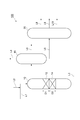
- FIG. 2 is a flowchart showing another example of a hydrocarbon oil production apparatus in which the method for producing a lubricating base oil according to the present invention is implemented.
- a lubricating base oil production apparatus 110 shown in FIG. 2 includes two reaction towers 30 and 40 connected in series via a transfer line L8 in place of the reaction tower 10 in the lubricating base oil production apparatus 100. It has the same configuration as the lubricating base oil manufacturing apparatus 100 except that it is provided.
- the reaction tower 30 includes the catalyst layer 16 similar to the first catalyst layer described above
- the reaction tower 40 includes the catalyst layer 18 similar to the second catalyst layer described above.
- the hydrogenation treatment in the reaction tower 30 and the counter response 40 can be performed under the following reaction conditions.
- Examples of the hydrogen partial pressure include 1 to 20 MPa, but 3 to 15 MPa is preferable.
- Examples of the hydrogen / oil ratio include 100 to 1500 NL / L, preferably 200 to 1000 NL / L.
- the ratio V1 / V2 between the volume V1 of the first catalyst constituting the catalyst layer 16 and the volume V2 of the second catalyst constituting the catalyst layer 18 is 70/30 to 90/10. .
- V1 / V2 is preferably 2.6 to 7.3, more preferably 3.0 to 5.7.
- the cross-sectional area when the first catalyst layer included in the reaction tower 30 and the second catalyst layer included in the reaction tower 40 are cut along a plane perpendicular to the flow direction is independent of the cutting position.
- the ratio [D3 / D4] between the thickness D3 of the first catalyst layer and the thickness D4 of the second catalyst layer shown in FIG. 2 may be in the range of 70/30 to 90/10. It is preferably in the range of 2.6 to 7.3, more preferably in the range of 3.0 to 5.7.
- the product oil obtained through the hydrogenation treatment can be further processed by, for example, hydrofinishing.
- the hydrofinishing can be generally carried out by bringing the work to be finished into contact with a supported metal hydrogenation catalyst (for example, alumina on which platinum and / or palladium is supported) in the presence of hydrogen.
- a supported metal hydrogenation catalyst for example, alumina on which platinum and / or palladium is supported
- the hydrofinishing may be performed in a reaction facility different from the line containing the first catalyst and the second catalyst, but includes the second catalyst according to the present invention provided in the reactor.
- a hydrogenation finishing catalyst layer may be provided on the downstream side of the second catalyst layer.
- ZSM-22 zeolite composed of crystalline aluminosilicate having a Si / Al ratio of 45 (hereinafter sometimes referred to as “ZSM-22”) was produced by hydrothermal synthesis according to the following procedure.
- Solution A 1.94 g of potassium hydroxide dissolved in 6.75 mL of ion exchange water.
- Solution B A solution obtained by dissolving 1.33 g of aluminum sulfate 18-hydrate in 5 mL of ion-exchanged water.
- Solution C A solution obtained by diluting 4.18 g of 1,6-hexanediamine (organic template) with 32.5 mL of ion-exchanged water.
- Solution D 18 g of colloidal silica (Ludox AS-40 manufactured by Grace Davison) diluted with 31 mL of ion-exchanged water.
- solution A was added to solution B and stirred until the aluminum component was completely dissolved.
- solution C was added to this mixed solution.
- the mixture of the solutions A, B and C was poured into the solution D with vigorous stirring at room temperature.
- 0.25 g of ZSM-22 powder synthesized separately and not subjected to any special treatment after the synthesis was added as a “seed crystal” to promote crystallization, thereby obtaining a gel-like product.
- the gel obtained by the above operation is transferred to a stainless steel autoclave reactor having an internal volume of 120 mL, and the autoclave reactor is rotated on a tumbling apparatus at a rotation speed of about 60 rpm in an oven at 150 ° C. for 60 hours.
- the hydrothermal synthesis reaction was performed. After completion of the reaction, the reactor was cooled and opened, and dried overnight in a dryer at 60 ° C. to obtain ZSM-22 having a Si / Al ratio of 45.
- ZSM-22 obtained above was subjected to ion exchange treatment with an aqueous solution containing ammonium ions by the following operation.
- ZSM-22 obtained as described above was placed in a flask, 100 mL of 0.5N ammonium chloride aqueous solution per 1 g of ZSM-22 zeolite was added, and the mixture was refluxed with heating for 6 hours. After cooling this to room temperature, the supernatant was removed and the crystalline aluminosilicate was washed with ion-exchanged water. The same amount of 0.5N-ammonium chloride aqueous solution as above was added again, and heated to reflux for 12 hours.
- the obtained viscous fluid was filled into an extrusion molding machine and molded to obtain a cylindrical molded body having a diameter of about 1.6 mm and a length of about 10 mm. This molded body was heated at 300 ° C. for 3 hours under an N 2 atmosphere to obtain a carrier precursor.
- Tetraamminedinitroplatinum [Pt (NH 3 ) 4 ] (NO 3 ) 2 was dissolved in ion-exchanged water corresponding to the previously measured water absorption of the carrier precursor to obtain an impregnation solution.
- This solution was impregnated with the above carrier precursor by an initial wetting method, and supported so that the amount of platinum was 0.3 mass% with respect to the mass of ZSM-22 zeolite.
- the obtained impregnated product (catalyst precursor) was dried overnight at 60 ° C., and then calcined at 400 ° C. for 3 hours under air flow, so that hydrogen having a carbon content of 0.56% by mass was obtained.
- Hydroisomerization catalyst E-1 was obtained.
- the amount of carbon was measured by combustion in an oxygen stream-infrared absorption method using EMIA-920V manufactured by Horiba.
- micropore volume per unit mass of the obtained hydroisomerization catalyst was calculated by the following method.
- pretreatment was performed to evacuate at 150 ° C. for 5 hours.
- the pretreatment hydroisomerization catalyst was subjected to nitrogen adsorption measurement at a liquid nitrogen temperature ( ⁇ 196 ° C.) using BELSORP-max manufactured by Nippon Bell Co., Ltd.
- the measured nitrogen adsorption isotherm was analyzed by the t-plot method, and the micropore volume (cc / g) per unit mass of the hydroisomerization catalyst was calculated.
- V Z V c / M z ⁇ 100
- V c the micropore volume per unit mass of the hydroisomerization catalyst
- M z the content ratio (mass%) of the zeolite contained in the catalyst.
- micropore volume per unit mass of the hydroisomerization catalyst E-1 is 0.055 cc / g, and the micropore volume per unit mass of the zeolite contained in the catalyst is 0.079 cc / g. there were.
- NH 4 type ZSM-22 obtained above and alumina as a binder were mixed at a mass ratio of 7: 3, and a small amount of ion-exchanged water was added thereto and kneaded.
- the obtained viscous fluid was filled into an extrusion molding machine and molded to obtain a cylindrical molded body having a diameter of about 1.6 mm and a length of about 10 mm. This molded body was heated at 300 ° C. for 3 hours under an N 2 atmosphere to obtain a carrier precursor.
- the carrier precursor obtained above was supported with platinum and palladium by the following method.
- tetraamminedinitroplatinum (II) and tetraamminedinitropalladium were dissolved in a minimum amount of ion-exchanged water.
- This solution was impregnated with the above-mentioned carrier precursor by an initial wetting method, and supported so that the amount of platinum was 0.1% by mass and the amount of palladium was 0.3% by mass with respect to the mass of ZSM-22. .
- these are dried overnight in a dryer at 60 ° C., fired at 400 ° C. for 3 hours under air flow, formed into a disk shape by tableting, further coarsely pulverized, and sieved. An irregular shaped particle having a maximum particle size of 125 to 250 ⁇ m was obtained. In this way, Catalyst E-2 was obtained.
- R-1 FT synthetic oil vacuum distillation bottom oil (boiling point 560 ° C. or higher, hydrocarbon content 21 or more hydrocarbon content: 100% by mass)
- R-2 Deasphalted oil obtained by removing asphalt from the vacuum distillation tower bottom oil of Middle East crude oil in the propane desulfurization step (content of hydrocarbons having a boiling point of 550 ° C. or higher and 21 or more carbon atoms: 100 mass%)
- Example 1 80 ml of catalyst E-1 was packed on the upstream side (upper layer) of the fixed bed reactor and 20 ml of catalyst E-2 on the downstream side (lower layer), and a two-layer catalyst layer was provided in the reactor.
- R-1 is supplied as raw material oil at LHSV: 1.0 h ⁇ 1 from the top of the reactor (upper side of the catalyst layer), and hydrogen is supplied at a hydrogen pressure of 5 MPa and a reaction temperature of 331 ° C. in a hydrogen stream. Processed.
- the product oil was distilled to obtain a fraction having a boiling point of 550 ° C. or higher.
- This fraction had a viscosity index of 159, a pour point of -15 ° C, and a cloud point of -10 ° C.
- the yield with respect to the raw material oil of this fraction was 80 mass%.
- the viscosity index, pour point, and cloud point were measured in accordance with a viscosity index calculation method specified by JIS K2283, a pour point test method specified by JIS K2269, and a cloud point test method specified by JIS K2269, respectively.
- Example 2 90 ml of catalyst E-1 was packed on the upstream side (upper layer) of the fixed bed reactor, and 10 ml of catalyst E-3 was packed on the downstream side (lower layer), and a two-layer catalyst layer was provided in the reactor.
- R-1 is supplied as a raw oil from the top of the reactor (upper side of the catalyst layer) at LHSV: 1.0 h ⁇ 1 , and hydrogen is supplied at a hydrogen pressure of 5 MPa and a reaction temperature of 321 ° C. in a hydrogen stream. Processed.
- the product oil was distilled to obtain a fraction having a boiling point of 550 ° C. or higher.
- This fraction had a viscosity index of 159, a pour point of -15 ° C, and a cloud point of -4 ° C.
- the yield with respect to the raw material oil of this fraction was 78 mass%.
- Example 3 70 ml of catalyst E-1 was packed on the upstream side (upper layer) of the fixed bed reactor, and 30 ml of catalyst E-4 was packed on the downstream side (lower layer), and a two-layer catalyst layer was provided in the reactor.
- R-1 as a raw material oil is supplied at LHSV: 1.0 h ⁇ 1 from the top of the reactor (upper layer of the catalyst layer), and hydrogen is supplied at a hydrogen pressure of 5 MPa and a reaction temperature of 318 ° C. in a hydrogen stream. Processed.
- the product oil was distilled to obtain a fraction having a boiling point of 550 ° C. or higher.
- This fraction had a viscosity index of 158, a pour point of -15 ° C, and a cloud point of -13 ° C.
- the yield with respect to the raw material oil of this fraction was 74 mass%.
- Example 4 80 ml of catalyst E-1 was packed on the upstream side (upper layer) of the fixed bed reactor and 20 ml of catalyst E-2 on the downstream side (lower layer), and a two-layer catalyst layer was provided in the reactor.
- R-2 is supplied as a raw material oil from the top of the reactor (upper side of the catalyst layer) at LHSV: 1.0 h ⁇ 1 , and hydrogen is supplied at a hydrogen pressure of 10 MPa and a reaction temperature of 341 ° C. Processed.
- the product oil was distilled to obtain a fraction having a boiling point of 550 ° C. or higher.
- This fraction had a viscosity index of 110, a pour point of -12.5 ° C, and a cloud point of -10 ° C.
- the yield with respect to the raw material oil of this fraction was 79 mass%.
- Example 5 80 ml of catalyst E-1 was packed on the upstream side (upper layer) of the fixed bed reactor and 20 ml of catalyst E-2 on the downstream side (lower layer), and a two-layer catalyst layer was provided in the reactor.
- R-3 is supplied as a raw oil at LHSV: 1.5 h ⁇ 1 , and hydrogen is supplied at a hydrogen pressure of 10 MPa and a reaction temperature of 345 ° C. in a hydrogen stream. Processed.
- the product oil was distilled to obtain a fraction having a boiling point of 550 ° C. or higher.
- the viscosity index of this fraction was 131, the pour point was ⁇ 15 ° C., and the cloud point was ⁇ 8 ° C.
- the yield with respect to the raw material oil of this fraction was 82 mass%.
- R-1 is supplied as a raw oil from the top of the reactor (upper side of the catalyst layer) at LHSV: 1.0 h ⁇ 1 , and hydrogen is supplied at a hydrogen pressure of 5 MPa and a reaction temperature of 330 ° C. in a hydrogen stream. Processed.
- the product oil was distilled to obtain a fraction having a boiling point of 550 ° C. or higher.
- the fraction had a viscosity index of 159, a pour point of ⁇ 15 ° C., and a cloud point of 15 ° C.
- the yield with respect to the raw material oil of this fraction was 68 mass%.
- R-2 is supplied as a raw oil at LHSV: 1.0 h ⁇ 1 , and hydrogen is supplied at a hydrogen pressure of 5 MPa and a reaction temperature of 331 ° C. in a hydrogen stream. Processed.
- the product oil was distilled to obtain a fraction having a boiling point of 550 ° C. or higher.
- This fraction had a viscosity index of 108, a pour point of -12.5 ° C, and a cloud point of 6 ° C.
- the yield with respect to the raw material oil of this fraction was 62 mass%.
- R-1 as a raw material oil is supplied at LHSV: 1.0 h ⁇ 1 from the top of the reactor (upper layer of the catalyst layer), and hydrogen is supplied at a hydrogen pressure of 5 MPa and a reaction temperature of 318 ° C. in a hydrogen stream. Processed.
- the product oil was distilled to obtain a fraction having a boiling point of 550 ° C. or higher.
- This fraction had a viscosity index of 159, a pour point of -15 ° C, and a cloud point of 10 ° C.
- the yield with respect to the raw material oil of this fraction was 76 mass%.
- R-1 is supplied as a raw oil at LHSV: 1.0 h ⁇ 1 , and hydrogen is supplied at a hydrogen pressure of 10 MPa and a reaction temperature of 345 ° C. Processed.
- the product oil was distilled to obtain a fraction having a boiling point of 550 ° C. or higher.
- This fraction had a viscosity index of 157, a pour point of ⁇ 15 ° C., and a cloud point of 14 ° C.
- the yield with respect to the raw material oil of this fraction was 81 mass%.
- a high viscosity index and a low viscosity are obtained by passing the raw material oil through the catalyst layer in which the first catalyst and the second catalyst according to the present invention are laminated at a predetermined ratio and performing the hydrogenation treatment.
- a lubricating base oil having a pour point and a sufficiently low cloud point can be obtained.
Landscapes
- Chemical & Material Sciences (AREA)
- Oil, Petroleum & Natural Gas (AREA)
- Chemical Kinetics & Catalysis (AREA)
- Organic Chemistry (AREA)
- General Chemical & Material Sciences (AREA)
- Crystallography & Structural Chemistry (AREA)
- Engineering & Computer Science (AREA)
- Materials Engineering (AREA)
- Production Of Liquid Hydrocarbon Mixture For Refining Petroleum (AREA)
- Catalysts (AREA)
- Lubricants (AREA)
- Silicates, Zeolites, And Molecular Sieves (AREA)
Abstract
Description
VZ=Vc/Mz×100
ノルマルパラフィンの転化率(%)=[1-(水素化処理後に得られる生成油100質量部に含まれる炭素数21以上のノルマルパラフィンの総質量部)/(水素化処理前の原料油100質量部に含まれる炭素数21以上のノルマルパラフィンの総質量部)]×100 …(I)
(製造例1)
<ZSM-22ゼオライトの製造>
Si/Al比が45である結晶性アルミノシリケートからなるZSM-22ゼオライト(以下、「ZSM-22」ということがある。)を以下の手順で水熱合成により製造した。
溶液A:1.94gの水酸化カリウムを6.75mLのイオン交換水に溶解したもの。
溶液B:1.33gの硫酸アルミニウム18水塩を5mLのイオン交換水に溶解したもの。
溶液C:4.18gの1,6-ヘキサンジアミン(有機テンプレート)を32.5mLのイオン交換水にて希釈したもの。
溶液D:18gのコロイダルシリカ(Grace Davison社製Ludox AS-40)を31mLのイオン交換水にて希釈したもの。
この混合溶液に溶液Cを加えた後、室温にて激しく攪拌しながら、溶液A、B、Cの混合物を溶液Dに注入した。更に、ここへ結晶化を促進する「種結晶」として、別途合成され、合成後に何ら特別な処理が行われていないZSM-22の粉末を0.25g添加し、ゲル状物を得た。
上記で得られたZSM-22について、以下の操作によりアンモニウムイオンを含む水溶液でイオン交換処理を行った。
上記で得たNH4型ZSM-22と、バインダーであるアルミナとを質量比7:3にて混合し、ここに少量のイオン交換水を添加して混錬した。得られた粘ちょうな流体を押出成型機に充填、成型し、直径約1.6mm、長さ約10mmの円筒状の成型体を得た。この成型体を、N2雰囲気下、300℃にて3時間加熱して、担体前駆体を得た。
テトラアンミンジニトロ白金[Pt(NH3)4](NO3)2を、担体前駆体のあらかじめ測定した吸水量に相当するイオン交換水に溶解して含浸溶液を得た。この溶液を、上記の担体前駆体に初期湿潤法により含浸し、ZSM-22ゼオライトの質量に対して、0.3質量%の白金量となるように担持を行った。次に、得られた含浸物(触媒前駆体)を60℃の乾燥中で一晩乾燥した後、空気流通下、400℃で3時間焼成して、カーボン量が0.56質量%である水素化異性化触媒E-1を得た。なお、カーボン量は、堀場製作所製EMIA-920Vを使用して、酸素気流中燃焼-赤外線吸収法で測定した。
VZ=Vc/Mz×100
式中、Vcは水素化異性化触媒の単位質量当りのミクロ細孔容積を示し、Mzは触媒に含有されるゼオライトの含有割合(質量%)を示す。
まず、製造例1と同様にして、Si/Al比が45であるZSM-22を得た。ZSM-22を石英管炉に充填し、窒素気流下、加熱して5℃/分の速度で400℃まで昇温し、そのまま6時間保持した。その後、流通する気体を酸素ガスに切替え、5℃/分の速度でさらに550℃まで昇温し、そのまま550℃にて一晩保持した。
白金及びパラジウムの担持量をそれぞれ0.1質量%及び0.1質量%としたこと以外は製造例2と同様にして、触媒E-3を得た。
白金及びパラジウムの担持量をそれぞれ0.1質量%及び0.2質量%としたこと以外は製造例2と同様にして、触媒E-4を得た。
白金及びパラジウムの担持量をそれぞれ0.01質量%及び0.01質量%としたこと以外は製造例2と同様にして、触媒E-5を得た。
以下の原料油を用意した。
R-1:FT合成油の減圧蒸留塔底油(沸点560℃以上、炭素数21以上の炭化水素の含有割合:100質量%)
R-2:中東原油の減圧蒸留塔底油をプロパン脱瀝工程でアスファルトを除いた脱アスファルト油(沸点550℃以上、炭素数21以上の炭化水素の含有割合:100質量%)
R-3:上記R-1と上記R-2とを容量比R-1/R-2=50/50で混合した混合油。
(実施例1)
固定床反応器の上流側(上層)に触媒E-1を80ml、下流側(下層)に触媒E-2を20mlそれぞれ充填し、反応器内に2層構成の触媒層を設けた。
固定床反応器の上流側(上層)に触媒E-1を90ml、下流側(下層)に触媒E-3を10mlそれぞれ充填し、反応器内に2層構成の触媒層を設けた。
固定床反応器の上流側(上層)に触媒E-1を70ml、下流側(下層)に触媒E-4を30mlそれぞれ充填し、反応器内に2層構成の触媒層を設けた。
固定床反応器の上流側(上層)に触媒E-1を80ml、下流側(下層)に触媒E-2を20mlそれぞれ充填し、反応器内に2層構成の触媒層を設けた。
固定床反応器の上流側(上層)に触媒E-1を80ml、下流側(下層)に触媒E-2を20mlそれぞれ充填し、反応器内に2層構成の触媒層を設けた。
固定床反応器に触媒E-1のみを100ml充填し、反応器内に1層構成の触媒層を設けた。
固定床反応器に触媒E-1のみを100ml充填し、反応器内に1層構成の触媒層を設けた。
固定床反応器の上流側(上層)に触媒E-1を95ml、下流側(下層)に触媒E-2を5mlそれぞれ充填し、反応器内に2層構成の触媒層を設けた。
固定床反応器の上流側(上層)に触媒E-1を80ml、下流側(下層)に触媒E-5を20mlそれぞれ充填し、反応器内に2層構成の触媒層を設けた。

Claims (3)
- 水素の存在下、炭素数が21以上の炭化水素を含む原料油を、第1の触媒及び第2の触媒にこの順で接触させる工程を有し、
前記第1の触媒が、10員環一次元状細孔構造を有するゼオライト、及びバインダーを含む担体と、該担体に担持された白金及び/又はパラジウムと、を含有する水素化異性化触媒であって、前記ゼオライトは、有機テンプレートを含有し10員環一次元状細孔構造を有する有機テンプレート含有ゼオライトを、アンモニウムイオン及び/又はプロトンを含む溶液中でイオン交換して得られるイオン交換ゼオライトに由来するものであり、触媒に含まれるカーボン量が0.4~3.5質量%であり、
前記第2の触媒が、10員環一次元状細孔構造を有するゼオライトを含む担体と、該担体に担持された白金及び/又はパラジウムと、を有し、前記白金及び/又はパラジウムの総担持量が金属原子換算で担体100質量部に対して0.05~0.4質量部である触媒であり、
前記第1の触媒の容積V1と前記第2の触媒の容積V2との比V1/V2が70/30~90/10であることを特徴とする潤滑油基油の製造方法。 - 前記第1の触媒が、触媒の単位質量当たりのミクロ細孔容積が0.02~0.12cc/gであり、触媒に含有されるゼオライトの単位質量当りのミクロ細孔容積が0.01~0.12cc/gであることを特徴とする請求項1に記載の潤滑油基油の製造方法。
- 水素の存在下、炭素数が21以上の炭化水素を含む原料油を、第1の触媒及び第2の触媒にこの順で接触させる工程を有し、
前記第1の触媒が、有機テンプレートを含有し10員環一次元状細孔構造を有する有機テンプレート含有ゼオライトを、アンモニウムイオン及び/又はプロトンを含む溶液中でイオン交換して得られるイオン交換ゼオライトと、バインダーと、が含まれる混合物を、N2雰囲気下、250~350℃の温度で加熱して担体前駆体を得る第1工程と、前記担体前駆体に白金塩及び/又はパラジウム塩を含ませた触媒前駆体を、分子状酸素を含む雰囲気下、350~400℃の温度で焼成して、ゼオライトを含む担体に白金及び/又はパラジウムが担持された水素化異性化触媒を得る第2工程と、を備える水素化異性化触媒の製造方法に得られる水素化異性化触媒であり、
前記第2の触媒が、10員環一次元状細孔構造を有するゼオライトを含む担体と、該担体に担持された白金及び/又はパラジウムと、を有し、前記白金及び/又はパラジウムの総担持量が金属原子換算で担体100質量部に対して0.05~0.4質量部である触媒であり、
前記第1の触媒の容積V1と前記第2の触媒の容積V2との比V1/V2が70/30~90/10であることを特徴とする潤滑油基油の製造方法。
Priority Applications (3)
| Application Number | Priority Date | Filing Date | Title |
|---|---|---|---|
| KR1020147028644A KR101607475B1 (ko) | 2012-03-30 | 2013-03-29 | 윤활유 기유의 제조 방법 |
| CN201380018574.5A CN104204152B (zh) | 2012-03-30 | 2013-03-29 | 润滑油基础油的制造方法 |
| ZA2014/06924A ZA201406924B (en) | 2012-03-30 | 2014-09-22 | Method for producing lubricant base oil |
Applications Claiming Priority (2)
| Application Number | Priority Date | Filing Date | Title |
|---|---|---|---|
| JP2012-082542 | 2012-03-30 | ||
| JP2012082542A JP5759409B2 (ja) | 2012-03-30 | 2012-03-30 | 潤滑油基油の製造方法 |
Publications (1)
| Publication Number | Publication Date |
|---|---|
| WO2013147184A1 true WO2013147184A1 (ja) | 2013-10-03 |
Family
ID=49260425
Family Applications (1)
| Application Number | Title | Priority Date | Filing Date |
|---|---|---|---|
| PCT/JP2013/059590 Ceased WO2013147184A1 (ja) | 2012-03-30 | 2013-03-29 | 潤滑油基油の製造方法 |
Country Status (6)
| Country | Link |
|---|---|
| JP (1) | JP5759409B2 (ja) |
| KR (1) | KR101607475B1 (ja) |
| CN (1) | CN104204152B (ja) |
| MY (1) | MY171890A (ja) |
| WO (1) | WO2013147184A1 (ja) |
| ZA (1) | ZA201406924B (ja) |
Families Citing this family (2)
| Publication number | Priority date | Publication date | Assignee | Title |
|---|---|---|---|---|
| JP6207432B2 (ja) * | 2014-03-11 | 2017-10-04 | Jxtgエネルギー株式会社 | 潤滑油組成物 |
| JP2019171337A (ja) * | 2018-03-29 | 2019-10-10 | Jxtgエネルギー株式会社 | 水素化触媒及び低芳香族溶剤の製造方法 |
Citations (4)
| Publication number | Priority date | Publication date | Assignee | Title |
|---|---|---|---|---|
| WO2009099111A1 (ja) * | 2008-02-08 | 2009-08-13 | Nippon Oil Corporation | 水素化異性化触媒及びその製造方法、炭化水素油の脱蝋方法、並びに潤滑油基油の製造方法 |
| JP2009242652A (ja) * | 2008-03-31 | 2009-10-22 | Nippon Oil Corp | 潤滑油基油の製造方法 |
| WO2011021513A1 (ja) * | 2009-08-18 | 2011-02-24 | Jx日鉱日石エネルギー株式会社 | 潤滑油基油の製造方法 |
| WO2012005981A2 (en) * | 2010-06-29 | 2012-01-12 | Chevron U.S.A. Inc. | CATALYTIC PROCESSES AND SYSTEMS FOR BASE OIL PRODUCTION USING ZEOLITE SSZ-32x |
Family Cites Families (7)
| Publication number | Priority date | Publication date | Assignee | Title |
|---|---|---|---|---|
| JP2002512580A (ja) | 1996-12-31 | 2002-04-23 | シェブロン ユー.エス.エー.インコーポレイテッド | ゼオライトssz−47 |
| ES2296989T3 (es) | 2001-07-13 | 2008-05-01 | Chevron U.S.A. Inc. | Zeolita ssz-58. |
| KR101463716B1 (ko) * | 2007-06-27 | 2014-11-19 | 제이엑스 닛코닛세키에너지주식회사 | 수소화 이성화 촉매, 탄화수소유의 탈랍 방법, 기유의 제조 방법 및 윤활유 기유의 제조 방법 |
| TWI473652B (zh) * | 2008-12-26 | 2015-02-21 | Nippon Oil Corp | Hydrogenated isomerization catalyst, method for producing the same, dewaxing method for hydrocarbon oil and method for producing lubricating base oil |
| CN101942320B (zh) * | 2009-07-09 | 2014-12-10 | 中国石油化工股份有限公司 | 一种异构脱蜡生产基础油方法 |
| US8617387B2 (en) * | 2010-06-29 | 2013-12-31 | Chevron U.S.A. Inc. | Catalytic processes and systems for base oil production from light feedstock |
| US8475648B2 (en) * | 2010-06-29 | 2013-07-02 | Chevron U.S.A. Inc. | Catalytic processes and systems for base oil production from heavy feedstock |
-
2012
- 2012-03-30 JP JP2012082542A patent/JP5759409B2/ja active Active
-
2013
- 2013-03-29 MY MYPI2014702750A patent/MY171890A/en unknown
- 2013-03-29 KR KR1020147028644A patent/KR101607475B1/ko active Active
- 2013-03-29 CN CN201380018574.5A patent/CN104204152B/zh active Active
- 2013-03-29 WO PCT/JP2013/059590 patent/WO2013147184A1/ja not_active Ceased
-
2014
- 2014-09-22 ZA ZA2014/06924A patent/ZA201406924B/en unknown
Patent Citations (4)
| Publication number | Priority date | Publication date | Assignee | Title |
|---|---|---|---|---|
| WO2009099111A1 (ja) * | 2008-02-08 | 2009-08-13 | Nippon Oil Corporation | 水素化異性化触媒及びその製造方法、炭化水素油の脱蝋方法、並びに潤滑油基油の製造方法 |
| JP2009242652A (ja) * | 2008-03-31 | 2009-10-22 | Nippon Oil Corp | 潤滑油基油の製造方法 |
| WO2011021513A1 (ja) * | 2009-08-18 | 2011-02-24 | Jx日鉱日石エネルギー株式会社 | 潤滑油基油の製造方法 |
| WO2012005981A2 (en) * | 2010-06-29 | 2012-01-12 | Chevron U.S.A. Inc. | CATALYTIC PROCESSES AND SYSTEMS FOR BASE OIL PRODUCTION USING ZEOLITE SSZ-32x |
Also Published As
| Publication number | Publication date |
|---|---|
| KR101607475B1 (ko) | 2016-03-30 |
| ZA201406924B (en) | 2015-12-23 |
| JP2013209604A (ja) | 2013-10-10 |
| CN104204152B (zh) | 2016-03-30 |
| MY171890A (en) | 2019-11-06 |
| JP5759409B2 (ja) | 2015-08-05 |
| CN104204152A (zh) | 2014-12-10 |
| KR20140145594A (ko) | 2014-12-23 |
Similar Documents
| Publication | Publication Date | Title |
|---|---|---|
| JP5468957B2 (ja) | 水素化異性化触媒、その製造方法、炭化水素油の脱蝋方法、炭化水素の製造方法及び潤滑油基油の製造方法 | |
| JP6228013B2 (ja) | 潤滑油基油の製造方法 | |
| JP5411864B2 (ja) | 潤滑油基油の製造方法及び潤滑油基油 | |
| JP6038779B2 (ja) | Zsm−22ゼオライト、水素化異性化触媒及びその製造方法、並びに炭化水素の製造方法 | |
| JP5312013B2 (ja) | 水素化異性化触媒、その製造方法、炭化水素油の脱蝋方法及び潤滑油基油の製造方法 | |
| WO2017033512A1 (ja) | 潤滑油基油の製造方法 | |
| WO2009099111A1 (ja) | 水素化異性化触媒及びその製造方法、炭化水素油の脱蝋方法、並びに潤滑油基油の製造方法 | |
| JP6050716B2 (ja) | 潤滑油基油の製造方法 | |
| JP6240501B2 (ja) | 潤滑油基油の製造方法 | |
| JPWO2013147219A1 (ja) | 水素化異性化触媒の製造方法及び潤滑油基油の製造方法 | |
| JP5757907B2 (ja) | 潤滑油基油の製造方法 | |
| JP5759409B2 (ja) | 潤滑油基油の製造方法 | |
| JP6204827B2 (ja) | 潤滑油基油の製造方法 | |
| JP6009196B2 (ja) | 潤滑油用基油の製造方法 | |
| JP6009197B2 (ja) | 潤滑油基油の製造方法 | |
| JP5998127B2 (ja) | 潤滑油用基油の製造方法 |
Legal Events
| Date | Code | Title | Description |
|---|---|---|---|
| WWE | Wipo information: entry into national phase |
Ref document number: 201380018574.5 Country of ref document: CN |
|
| 121 | Ep: the epo has been informed by wipo that ep was designated in this application |
Ref document number: 13768476 Country of ref document: EP Kind code of ref document: A1 |
|
| NENP | Non-entry into the national phase |
Ref country code: DE |
|
| ENP | Entry into the national phase |
Ref document number: 20147028644 Country of ref document: KR Kind code of ref document: A |
|
| WWE | Wipo information: entry into national phase |
Ref document number: IDP00201406596 Country of ref document: ID |
|
| 122 | Ep: pct application non-entry in european phase |
Ref document number: 13768476 Country of ref document: EP Kind code of ref document: A1 |