WO2013146597A1 - 加圧流動炉システムの起動方法 - Google Patents
加圧流動炉システムの起動方法 Download PDFInfo
- Publication number
- WO2013146597A1 WO2013146597A1 PCT/JP2013/058328 JP2013058328W WO2013146597A1 WO 2013146597 A1 WO2013146597 A1 WO 2013146597A1 JP 2013058328 W JP2013058328 W JP 2013058328W WO 2013146597 A1 WO2013146597 A1 WO 2013146597A1
- Authority
- WO
- WIPO (PCT)
- Prior art keywords
- pressurized fluidized
- fluidized furnace
- supplied
- combustion
- furnace
- Prior art date
Links
Images


Classifications
-
- F—MECHANICAL ENGINEERING; LIGHTING; HEATING; WEAPONS; BLASTING
- F23—COMBUSTION APPARATUS; COMBUSTION PROCESSES
- F23G—CREMATION FURNACES; CONSUMING WASTE PRODUCTS BY COMBUSTION
- F23G5/00—Incineration of waste; Incinerator constructions; Details, accessories or control therefor
- F23G5/30—Incineration of waste; Incinerator constructions; Details, accessories or control therefor having a fluidised bed
-
- F—MECHANICAL ENGINEERING; LIGHTING; HEATING; WEAPONS; BLASTING
- F23—COMBUSTION APPARATUS; COMBUSTION PROCESSES
- F23C—METHODS OR APPARATUS FOR COMBUSTION USING FLUID FUEL OR SOLID FUEL SUSPENDED IN A CARRIER GAS OR AIR
- F23C10/00—Fluidised bed combustion apparatus
- F23C10/16—Fluidised bed combustion apparatus specially adapted for operation at superatmospheric pressures, e.g. by the arrangement of the combustion chamber and its auxiliary systems inside a pressure vessel
-
- F—MECHANICAL ENGINEERING; LIGHTING; HEATING; WEAPONS; BLASTING
- F23—COMBUSTION APPARATUS; COMBUSTION PROCESSES
- F23C—METHODS OR APPARATUS FOR COMBUSTION USING FLUID FUEL OR SOLID FUEL SUSPENDED IN A CARRIER GAS OR AIR
- F23C10/00—Fluidised bed combustion apparatus
- F23C10/18—Details; Accessories
-
- F—MECHANICAL ENGINEERING; LIGHTING; HEATING; WEAPONS; BLASTING
- F23—COMBUSTION APPARATUS; COMBUSTION PROCESSES
- F23G—CREMATION FURNACES; CONSUMING WASTE PRODUCTS BY COMBUSTION
- F23G5/00—Incineration of waste; Incinerator constructions; Details, accessories or control therefor
- F23G5/44—Details; Accessories
-
- F—MECHANICAL ENGINEERING; LIGHTING; HEATING; WEAPONS; BLASTING
- F23—COMBUSTION APPARATUS; COMBUSTION PROCESSES
- F23G—CREMATION FURNACES; CONSUMING WASTE PRODUCTS BY COMBUSTION
- F23G5/00—Incineration of waste; Incinerator constructions; Details, accessories or control therefor
- F23G5/50—Control or safety arrangements
-
- F—MECHANICAL ENGINEERING; LIGHTING; HEATING; WEAPONS; BLASTING
- F23—COMBUSTION APPARATUS; COMBUSTION PROCESSES
- F23L—SUPPLYING AIR OR NON-COMBUSTIBLE LIQUIDS OR GASES TO COMBUSTION APPARATUS IN GENERAL ; VALVES OR DAMPERS SPECIALLY ADAPTED FOR CONTROLLING AIR SUPPLY OR DRAUGHT IN COMBUSTION APPARATUS; INDUCING DRAUGHT IN COMBUSTION APPARATUS; TOPS FOR CHIMNEYS OR VENTILATING SHAFTS; TERMINALS FOR FLUES
- F23L5/00—Blast-producing apparatus before the fire
-
- F—MECHANICAL ENGINEERING; LIGHTING; HEATING; WEAPONS; BLASTING
- F23—COMBUSTION APPARATUS; COMBUSTION PROCESSES
- F23C—METHODS OR APPARATUS FOR COMBUSTION USING FLUID FUEL OR SOLID FUEL SUSPENDED IN A CARRIER GAS OR AIR
- F23C2900/00—Special features of, or arrangements for combustion apparatus using fluid fuels or solid fuels suspended in air; Combustion processes therefor
- F23C2900/10001—Use of special materials for the fluidized bed
-
- F—MECHANICAL ENGINEERING; LIGHTING; HEATING; WEAPONS; BLASTING
- F23—COMBUSTION APPARATUS; COMBUSTION PROCESSES
- F23C—METHODS OR APPARATUS FOR COMBUSTION USING FLUID FUEL OR SOLID FUEL SUSPENDED IN A CARRIER GAS OR AIR
- F23C2900/00—Special features of, or arrangements for combustion apparatus using fluid fuels or solid fuels suspended in air; Combustion processes therefor
- F23C2900/10002—Treatment devices for the fluidizing gas, e.g. cooling, filtering
-
- F—MECHANICAL ENGINEERING; LIGHTING; HEATING; WEAPONS; BLASTING
- F23—COMBUSTION APPARATUS; COMBUSTION PROCESSES
- F23C—METHODS OR APPARATUS FOR COMBUSTION USING FLUID FUEL OR SOLID FUEL SUSPENDED IN A CARRIER GAS OR AIR
- F23C2900/00—Special features of, or arrangements for combustion apparatus using fluid fuels or solid fuels suspended in air; Combustion processes therefor
- F23C2900/10006—Pressurized fluidized bed combustors
-
- F—MECHANICAL ENGINEERING; LIGHTING; HEATING; WEAPONS; BLASTING
- F23—COMBUSTION APPARATUS; COMBUSTION PROCESSES
- F23C—METHODS OR APPARATUS FOR COMBUSTION USING FLUID FUEL OR SOLID FUEL SUSPENDED IN A CARRIER GAS OR AIR
- F23C2900/00—Special features of, or arrangements for combustion apparatus using fluid fuels or solid fuels suspended in air; Combustion processes therefor
- F23C2900/99006—Arrangements for starting combustion
Definitions
- the present invention relates to a method for starting a pressurized fluidized furnace system for burning an object to be treated such as sewage sludge, biomass, municipal waste, and more specifically, cracking of fluidized sand deposited at the bottom of the pressurized fluidized furnace. It is related with the starting method of the pressurization fluidized-furnace system which reduces the consumption frequency of the auxiliary
- a pressurized fluidized furnace system has been known as an incineration facility that focuses on effectively taking out the energy of combustion exhaust gas discharged from an incinerator by burning an object to be treated such as sewage sludge, biomass, and municipal waste.
- the pressurized fluidized furnace system is a pressurized fluidized furnace that combusts a workpiece, a turbine that is rotated by combustion exhaust gas discharged from the pressurized fluidized furnace, and is rotated as the turbine rotates to supply compressed air. It is the system characterized by having the supercharger which mounts the compressor which carries out.
- the conventional method for starting up the pressurized fluidized furnace system is that the fluidized sand heated to about 550 ° C. with the temperature rise of the pressurized fluidized furnace comes into contact with the normal temperature water sprayed in the furnace, so that the fluidized sand There is a concern that the consumption of fluidized sand may increase because cracks occur in the sand.
- the startup method of the pressurized fluidized furnace system described in Non-Patent Document 1, Patent Documents 1 and 2 uses auxiliary fuel such as heavy oil and city gas to maintain the exhaust gas temperature and the exhaust gas flow rate until the self-sustained operation is completed. There is a risk that the consumption is high.
- the main problem of the present invention is to eliminate such problems.
- a pressurized fluidizing furnace for burning a workpiece having a water-containing organic substance by filling fluidized sand at the bottom, a turbine rotated by combustion exhaust gas discharged from the pressurized fluidized furnace, and a turbine rotation.
- a supercharger that includes a compressor that rotates with movement and supplies compressed air as combustion air to the pressurized fluidized furnace, a starter fan that supplies combustion air to the pressurized fluidized furnace, and the pressurized fluidized furnace
- a method of starting a pressurized fluidized furnace system comprising heating means for heating the inside, Drive the starter blower to supply combustion air to the pressurized fluidized furnace, The fluidized sand is heated by the heating means to raise the temperature of the freeboard part of the pressurized fluidized furnace, After the temperature of the free board portion is raised to 750 to 900 ° C., an object to be treated is supplied to the pressurized fluidized furnace to increase combustion exhaust gas, The starter blower is stopped after the turbocharger is driven by the combustion exhaust gas to supply the combustion air to the pressurized fluidized furnace.
- the third invention is characterized in that, in the configuration of the first or second invention, the supply of the object to be processed is started when the pressure in the pressurized fluidized furnace becomes constant for a predetermined time.
- the operation of the supercharger is more preferably started without increasing the amount of combustion exhaust gas with a water gun or the like. be able to.
- the flue gas supplied to the turbine after the flue gas supplied to the turbine reaches a predetermined temperature, it branches from the flow path from the discharge side of the starter blower to the compressor suction side.
- the bypass flow path disposed between the compressor discharge side flow path is closed, and combustion air is supplied from the starter blower to the compressor supply port via the air flow path.
- the fifth invention is characterized in that, in the configurations of the first to fourth inventions, the object to be processed is supplied to the pressurized fluidized furnace while being increased at a constant rate.
- the sixth invention is characterized in that, in the configurations of the first to fourth inventions, the workpieces are supplied to the pressurized fluidized furnace while being increased stepwise.
- the object to be processed Since the object to be processed is supplied to the pressurized fluidized furnace while being increased stepwise, the method for supplying the object to be processed can be easily performed, and fluctuations in the supply amount of the object to be processed can be suppressed. Moreover, the fluctuation
- the material to be treated is supplied in an amount of 20 to 30% by mass of the rated throughput of the pressurized fluidized furnace, After the combustion air supplied from the supercharger reaches 50 vol% or more of the rated capacity, the object to be processed is supplied in an amount of 40 to 50% by mass of the rated processing amount.
- the pressurized fluidized furnace includes a starter burner for heating the fluidized sand filled in the bottom as a heating means, and an auxiliary fuel combustion device, The temperature of the fluidized sand is raised to 650 to 700 ° C. by the starter burner, and then the fluidized sand is heated to 750 to 850 ° C. by the auxiliary fuel combustion device.
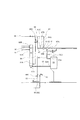
- the pressurized fluidized furnace system 1 includes a storage device 10 that stores an object to be processed such as sludge, a pressurized fluidized furnace 20 that combusts the object to be processed supplied from the storage device 10, An air preheater 40 for heating the combustion air supplied to the pressurized fluidized furnace 20 by the combustion exhaust gas discharged from the pressure fluidized furnace 20, a dust collector 50 for removing dust and the like in the combustion exhaust gas, and pressurization driven by the combustion exhaust gas A supercharger 60 for supplying combustion air to the fluidized furnace 20, a white smoke prevention preheater 70 for heating the white smoke prevention air supplied to the flue gas treatment tower 80 by the combustion exhaust gas discharged from the supercharger 60, and And a flue gas treatment tower 80 for removing impurities in the combustion exhaust gas.
- a storage device 10 that stores an object to be processed such as sludge
- a pressurized fluidized furnace 20 that combusts the object to be processed supplied from the storage device 10
- An air preheater 40
- the object to be treated stored in the storage device 10 is mainly sewage sludge dehydrated to a moisture content of 70 to 85% by mass, and the object to be treated contains combustible organic matter.
- a to-be-processed object is a water-containing organic substance, it will not be restrict
- a fixed amount feeder 11 for supplying a predetermined amount of the object to be processed to the pressurized fluidized furnace 20 is disposed in the lower part of the storage device 10, and the object to be processed is pumped to the pressurized fluidized furnace 20 on the downstream side of the quantitative feeder 11.
- a dosing pump 12 is provided.
- the pressurized fluidized furnace 20 is a combustion furnace having a predetermined particle size as a fluidized medium and filled with solid particles such as fluidized sand in the lower part of the furnace, and a fluidized bed (hereinafter referred to as a fluidized bed) by combustion air supplied into the furnace.
- the material to be processed supplied from the outside and auxiliary fuel supplied as necessary are burned while maintaining the fluid state of the sand layer.
- the pressurized fluidized furnace 20 includes at least one of an auxiliary fuel combustion device 21 and a starting burner 22 as heating means. As shown in FIGS.
- an auxiliary fuel combustion device 21 for heating the fluidized sand having a particle size of about 400 to 600 ⁇ m filled in the pressurized fluidized furnace 20 is disposed at the lower part of the side wall on one side.
- a starter burner 22 that heats the fluidized sand at the time of start-up is disposed in a portion near the upper side of the auxiliary fuel combustion device 21, and a workpiece supply port 13 ⁇ / b> B is provided in the upper portion of the starter burner 22.
- a water gun 23 for cooling the combustion exhaust gas is disposed at the upper part of the pressurized fluidized furnace 20, and cooling water can be sprayed into the furnace as necessary.
- the auxiliary fuel combustion device 21 is arranged above the combustion air supply pipe (dispersion pipe) 24 in order to heat the fluidized sand filled in the pressurized fluidized furnace 20. Further, a plurality of auxiliary fuel combustion devices 21 are arranged in parallel in the same manner as the combustion air supply pipe 24.
- the auxiliary fuel combustion device 21 is supplied with auxiliary fuel such as city gas or heavy oil from an auxiliary fuel supply device 29 installed outside the furnace. A gas gun or an oil gun can be used as the auxiliary fuel combustion device 21.
- the starting burner 22 is disposed so as to fall and incline toward the center of the pressurized fluidized furnace 20 in order to heat the upper surface of the fluidized sand at the time of starting. Similar to the auxiliary fuel combustion device 21, auxiliary fuel is supplied to the start burner 22 from an auxiliary fuel supply device 29 outside the furnace. Further, as the combustion air of the starter burner 22, the blown air generated by the starter blower 65 through the pipe 96 is used.
- a combustion air supply pipe 24 that supplies combustion air to the inside of the pressurized fluidized furnace 20 is disposed under the side wall on the other side of the pressurized fluidized furnace 20.
- the thinned side wall at the top of the pressurized fluidized furnace 20 is heated with combustion gas generated by the combustion of the auxiliary fuel, the object to be processed, sand filtered water, water existing in the object to be processed, etc.
- a discharge port 90 ⁇ / b> A is formed for discharging the water vapor generated in step 1 to the outside of the furnace.
- combustion gas or a gas in which combustion gas and water vapor are mixed is referred to as combustion exhaust gas.
- the combustion air supply pipe 24 is disposed below the auxiliary fuel combustion device 21 in order to supply combustion air evenly to the auxiliary fuel supplied from the auxiliary fuel combustion device 21.
- a plurality of temperature sensors (not shown) for measuring the in-furnace temperature are installed on the side wall of the pressurized flow furnace 20 at predetermined intervals along the height direction.
- the installation locations are the sand layer and the freeboard section, which are 2 to 3 places each, 4 to 6 places in total.
- a thermocouple or the like can be used as the temperature sensor.
- the free board portion refers to the upper layer portion of the sand layer in the pressurized fluidized bed combustion furnace 11.
- the air preheater 40 is installed at the rear stage of the pressurized fluidized furnace 20 and indirectly exchanges heat between the combustion exhaust gas discharged from the pressurized fluidized furnace 20 and the combustion air, thereby raising the combustion air to a predetermined temperature. It is a device that warms up. As shown in FIGS. 1 and 3, the air preheater 40 has a combustion exhaust gas supply port 90 ⁇ / b> B from the pressurized fluidized furnace 20 formed at the upper portion of one side wall, and a lower vicinity portion of the supply port 90 ⁇ / b> B. Is formed with a discharge port 91 ⁇ / b> A through which combustion air is discharged from the air preheater 40.
- the combustion exhaust gas supply port 90 ⁇ / b> B is connected to the discharge port 90 ⁇ / b> A of the pressurized fluidized furnace 20 through the pipe 90, and the combustion air exhaust port 91 ⁇ / b> A is supplied to the combustion air of the pressurized fluidized furnace 20 through the tube 91. Connected to the rear of the tube 24.
- a discharge port 92A for discharging the combustion exhaust gas from the air preheater 40 is formed in the lower part on the other side of the air preheater 40, and a supply port for supplying combustion air into the device in a region near the upper side of the discharge port 92A 95B is formed.
- the air preheater a shell and tube heat exchanger is preferable.
- the dust collector 50 is provided in the subsequent stage of the air preheater 40 and is a device that removes impurities such as dust and finely divided fluidized sand contained in the combustion exhaust gas delivered from the air preheater 40.
- a filter installed in the dust collector 50 for example, a ceramic filter or a bag filter can be used.
- a supply port 92B for supplying combustion exhaust gas into the device is formed in a lower portion of one side wall.
- a discharge port 93A for discharging clean combustion exhaust gas from which impurities and the like have been removed to the outside of the device is formed.
- the combustion exhaust gas supply port 92 ⁇ / b> B is connected to the combustion exhaust gas discharge port 92 ⁇ / b> A of the air preheater 40 through a pipe 92.
- a vacuum filter (not shown) is provided at a portion between the supply port 92B formed in the lower portion and the discharge port 93A formed in the upper portion in the vertical direction. Impurities and the like in the combustion exhaust gas removed by the filter are temporarily stored at the bottom in the dust collector 50 and then periodically discharged to the outside.
- the supercharger 60 is provided at the rear stage of the dust collector 50, and is rotated by the turbine 61 rotated by the combustion exhaust gas sent from the dust collector 50, the shaft 63 that transmits the rotation of the turbine 61, and the shaft 63.
- the compressor 62 generates compressed air by being transmitted.
- the generated compressed air is supplied to the pressurized fluidized furnace 20 as combustion air.
- a supply port 93 ⁇ / b> B for supplying clean combustion exhaust gas from which impurities have been removed by the dust collector 50 into the apparatus is formed at a lower portion of the side wall of the turbocharger 60 on the turbine 61 side (a portion orthogonal to the shaft 63).
- a discharge port 97A for discharging combustion exhaust gas to the outside of the device is formed on the downstream side of the side wall (portion parallel to the shaft 63). Further, the combustion exhaust gas supply port 93 ⁇ / b> B is connected to the discharge port 93 ⁇ / b> A of the dust collector 50 through the pipe 93.
- the pipe 93 is provided with temperature measuring means 93D for measuring the combustion exhaust gas temperature.
- a supply port 67B for sucking air into the equipment is formed, and above the side wall on the turbine 61 side (perpendicular to the shaft 63).
- a discharge port 94A for discharging compressed air obtained by increasing the pressure of the sucked air to 0.05 to 0.3 MPa is formed in the device.
- the outside air supply port 67 ⁇ / b> B sucks air through the pipes 16 and 67. Further, it is also connected to a starter blower 65 that supplies combustion air to the pressurized fluidized furnace 20 at the time of start-up via pipes 66 and 67.
- the pipe 67 is provided with pressure measuring means 67C for measuring the pressure in the pipe.
- the compressed air discharge port 94 ⁇ / b> A is connected to the supply port 95 ⁇ / b> B of the air preheater 40 via the pipes 94, 95 and to the rear part of the starting burner 22 of the pressurized fluidized furnace 20 via the pipes 94, 96. Yes.
- the starter blower 65 is a device that supplies the flowing air of the pressurized fluidized furnace 20 and the combustion air to the starting burner 22 when the pressurized fluidized furnace system 1 is started.
- the starter blower 65 reduces the water vapor generated in the pressurized fluidized furnace 20 due to the interruption of the supply of the object to be processed from the storage device 10 and the rotation speed of the turbine 61 of the supercharger 60 becomes low.
- the start blower 65 is connected to the discharge side pipe 94 of the compressor 62 via the pipes 66 and 68.
- a damper 68 ⁇ / b> C that communicates a portion of the pipe 68 far from the connection point with the pipe 67 as viewed from the starter fan 65 is disposed in the middle portion of the pipe 68 that is a bypass flow path.
- the damper 68C communicates the pipe 68 from the time when the pressurized fluidized furnace 20 is started (when the starter burner 22 is ignited) until the temperature rise of the pressurized fluidized furnace 20 is completed.
- the pipe 68 is shut off. That is, during the temperature rise from the start of the pressurized fluidized furnace 20, the air generated by the starter blower 65 is burned by the starter burner via the pipe 96 to the starter burner 22 provided in the pressurized fluidized furnace 20.
- the compressor of the supercharger 60 is supplied as air, and further supplied to the combustion air supply pipe 24 through the pipe 95 and the air preheater 40, and through the pipe 67 which is an unclosed air flow path. After the combustion air is supplied also to the 62 side and the temperature rise of the pressurized fluidized furnace 20 is completed, only the air that has passed through the compressor 62 is closed via the air preheater 40 by closing the damper 68C. Is supplied to the combustion air supply pipe 24 as combustion air.
- the white smoke prevention preheater 70 prevents the white smoke of the combustion exhaust gas discharged from the chimney 87 to the outside, and the white smoke prevention supplied from the combustion exhaust gas discharged from the supercharger 60 and the white smoke prevention fan. It is a device that indirectly exchanges heat with industrial air. By the heat exchange treatment, the combustion exhaust gas is cooled and the white smoke prevention air is heated. The flue gas that has been heat-exchanged and cooled by the white smoke prevention preheater 70 is sent to the subsequent flue gas treatment tower 80.
- a shell and tube heat exchanger, a plate heat exchanger, or the like can be used as the white smoke preventing preheater 70.
- the flue gas treatment tower 80 is a device that prevents discharge of impurities and the like contained in the combustion exhaust gas outside the equipment, and a chimney 87 is disposed on the upper part of the flue gas treatment tower 80.
- the flue gas treatment tower 80 has a supply port 98 ⁇ / b> B for supplying the combustion exhaust gas discharged from the white smoke prevention preheater 70 into the apparatus at the lower part of the side wall on one side.
- a supply port 99B is formed in the lower portion of the side wall on one side of the chimney 87 to supply the white smoke prevention air, which is heated and discharged from the white smoke prevention preheater 70 and exchanged with the exhaust gas, into the chimney 87.
- the combustion exhaust gas supply port 98B is connected to a combustion exhaust gas discharge port 98A formed in the lower portion of the white smoke prevention preheater 70 via a pipe 98, and the white smoke prevention air supply port 99B is connected to the pipe.
- 99 is connected to a white smoke prevention air discharge 99 ⁇ / b> A formed in the upper part of the white smoke prevention preheater 70.
- the white smoke prevention air of the white smoke prevention preheater 70 is supplied to the white smoke prevention preheater 70 via the pipe 103 by the white smoke prevention air blower 101 and indirectly exchanged with the combustion exhaust gas. It is heated and discharged from the discharge port 99A.
- the combustion exhaust gas at the outlet which tends to be wet and condensed in the air, is mixed with warm and dry white smoke prevention air at the supply port 99B to reduce the relative humidity of the combustion exhaust gas. To prevent white smoke.
- a spray pipe 84 for spraying water supplied from the outside into the apparatus is arranged on the upper side wall on the other side of the flue gas treatment tower 80, and the intermediate part and the lower part are respectively connected via a circulation pump 83.
- a spray pipe 85 for spraying caustic soda water containing caustic soda stored at the bottom of the flue gas treatment tower 80 into the apparatus is disposed. Further, the caustic soda water stored in the flue gas processing tower 80 is supplied from a caustic soda tank (not shown) via a caustic soda pump (not shown), and is always maintained at an appropriate amount.
- the combustion exhaust gas supplied to the flue gas treatment tower 80 is mixed with white smoke prevention air after removing impurities and the like, and is discharged from the chimney 87 to the outside.
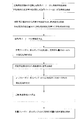
- the starting method of the pressurized fluidized furnace system 1 of this embodiment is demonstrated based on FIG.
- This activation method is an activation method that prevents the fluid sand from being rapidly cooled and broken by water sprayed from the water gun 23.
- the starter blower 65 that sucks outside air is started, and combustion air is supplied from the starter blower 65 to the starter burner 22.
- the combustion air discharged from the starter blower 65 is supplied to the rear portion of the starter burner 22 through the pipes 66, 68 and 96.
- the damper 66C disposed in the pipe 66 is connected to the control device, and is opened when the starter blower 65 operates, so that the pipe 66 communicates.
- a damper 68 ⁇ / b> C that is disposed in the pipe 68 and communicates with a portion far from the connection point with the pipe 67 as viewed from the starter fan 65 is connected to the control device, and the pipe 68 communicates.
- a part of the combustion air discharged from the starter blower 65 may be supplied to the starter burner 22 via the compressor 62 and the pipe 94 of the supercharger 60, but is discharged from the starter blower 65. More than half of the combustion air may be supplied to the start burner 22 without passing through the compressor 62.
- the auxiliary fuel supply device 29 arranged outside the furnace is started, and auxiliary fuel such as heavy oil and city gas is supplied from the auxiliary fuel supply device 29 to the starter burner 22.
- auxiliary fuel discharged from the auxiliary fuel supply device 29 is supplied to the rear portion of the starting burner 22 via the pipes 30 and 31.
- the flow rate adjustment valve 31C disposed in the pipe 31 is connected to a control device (not shown) and adjusts the flow rate (supply amount) of auxiliary fuel.
- the combustion air and auxiliary fuel supplied to the starter burner 22 are mixed by the starter burner 22 and combusted, and hot air is ejected from the discharge port at the front of the starter burner 22.
- the hot air ejected from the starter burner 22 is ejected toward the upper surface of the fluidized sand filled in the bottom of the pressurized fluidized furnace 20 to raise the temperature of the sand layer to about 650 to 700 ° C.
- combustion air is continuously supplied from the starter blower 65 to the combustion air supply pipe 24.
- the combustion air discharged from the starter blower 65 is supplied to the rear portion of the combustion air supply pipe 24 through the pipes 66, 68, 96, 95, the air preheater 40, and the pipe 91.
- the flow rate adjusting valve 95C disposed in the pipe 95 is connected to a control device, and the pipe 95 is communicated so as to flow an appropriate flow rate.
- a part of the combustion air discharged from the starter blower 65 may be supplied to the combustion air supply pipe 24 via the compressor 62 and the pipe 94 of the supercharger 60, but from the starter blower 65. More than half of the discharged combustion air may be supplied to the combustion air supply pipe 24 without passing through the compressor 62.
- Auxiliary fuel is supplied from the auxiliary fuel supply device 29 to the auxiliary fuel combustion device 21.
- the auxiliary fuel discharged from the auxiliary fuel supply device 29 is supplied to the rear portion of the auxiliary fuel combustion device 21 through the pipes 30 and 32.
- the flow rate adjustment valve 32C disposed in the pipe 31 is controlled by a control device (not shown) to adjust the flow rate (supply amount) of auxiliary fuel.
- the combustion air supplied to the combustion air supply pipe 24 is discharged from the hole at the tip of the combustion air supply pipe 24 to the packed bed of fluidized sand, and the auxiliary fuel supplied to the auxiliary fuel combustion device 21 is the auxiliary fuel combustion device.
- 21 is discharged to the packed bed of fluidized sand from the hole at the front, and combustion air and auxiliary fuel are mixed and combusted in the fluidized sand gap to generate hot air, and the temperature of the fluidized sand is raised to 750-850 ° C. Let warm. Further, the freeboard temperature of the pressurized fluidized furnace 20 (the temperature at the upper part in the pressurized fluidized furnace 20) rises in response to the temperature rise of the fluidized sand and is raised to about 850 ° C.
- the combustion exhaust gas discharged from the pressurized fluidized furnace 20 is supplied to the air preheater 40 through the pipe 90 and then passes through the dust collector 50.
- the combustion exhaust gas discharged from the dust collector 50 is supplied to the smoke processing tower 80 via the pipe 93C and then discharged to the outside from the chimney 87. At this time, a part of the combustion exhaust gas may be supplied to the turbine 61 of the supercharger 60.
- the combustion of the start burner 22 is stopped. That is, the damper 96C of the pipe 96 is disconnected from the control device, the pipe 96 is closed to stop the supply of combustion air, and the flow rate adjustment valve 31C of the pipe 31 is closed to stop the supply of auxiliary fuel.
- the quantitative feeder 11 When the temperature of the free board portion in the pressurized fluidized furnace 20 is raised to about 750 to 900 ° C., and the combustion air flow rate and the pressure in the furnace become constant for about 1 to 10 seconds, the quantitative feeder 11 Then, the charging pump 12 is started, and the workpiece is supplied into the pressurized fluidized furnace 20 from the supply port 13B of the pressurized fluidized furnace 20.
- the organic substance contained in the object to be processed supplied into the pressurized fluidized furnace 20 burns to generate combustion gas, and the moisture contained in the object to be treated is the upper part in the pressurized fluidized furnace 20 or flows. Boils in contact with sand and generates water vapor.
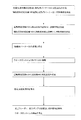
- the supply amount of the object to be processed is preferably 20 to 30% of the rated processing amount of the pressurized fluidized furnace 20.
- the amount is less than 20% of the rated processing amount, the amount of combustion exhaust gas generated is small, and the time for the supercharger 60 to shift to the self-sustained operation becomes long.
- the supply amount is more than 30% of the rated processing amount, the fluid sand breaks due to the water contained in the object to be processed, and the particle size cannot be sufficiently prevented.
- the rated processing amount refers to the mass of the workpiece to be supplied from the supply port 13B to the pressurized fluidized furnace 20 during the self-sustained operation of the supercharger 60.
- combustion air is supplied from the starter blower 65 to the compressor 62.
- the combustion air discharged from the starter blower 65 is supplied to the compressor 62 via the pipes 66 and 67. Further, the outside air can be supplied to the compressor 62 as combustion air through the pipes 16, 66, and 67.
- the supplied combustion air is pressurized to 0.05 to 0.3 Mpa by the compressor 62 and then supplied to the rear portion of the combustion air supply pipe 24 through the pipes 94, 96, 95, the air preheater 40, and the pipe 91.
- the damper 68C arrange
- the rated throughput is set in the pressurized fluidized furnace 20 from the supply port 13B of the pressurized fluidized furnace 20.
- a lower amount of workpiece is supplied.
- the supply amount is preferably 40 to 50% of the rated processing amount.
- the supply amount of the object to be processed is less than 40% of the rated processing amount, a small amount of combustion exhaust gas is generated, and the time required for the amount of combustion air discharged from the supercharger 60 to increase to a predetermined amount becomes long. . Further, if the supply amount is more than 50% of the rated treatment amount, it becomes difficult to keep the temperature of the fluid sand in the pressurized fluidized furnace 20 constant by the water contained in the workpiece.
- the combustion exhaust gas increases, and the rotation speed of the supercharger 60 increases, the amount of air that can be sucked by the compressor 62 increases. Therefore, the amount of combustion air supplied from the starter blower 65 is decreased while increasing the amount of combustion air supplied to the compressor 62 of the supercharger 60 via the pipes 16, 66 and 67. Adjustment of the amount of combustion air may reduce the rotation speed of a blower, and may adjust the damper 66C opening degree. Thereafter, when the pressure measured by the pressure detection means 67C installed in the pipe 67 becomes lower than the atmospheric pressure, the starter blower 65 is stopped.
- the pressurized fluidized furnace system 1 is in a self-sustained operation in which the turbine 61 is driven by the combustion exhaust gas and the necessary amount of combustion air for the object to be processed is supplied by the compressed air discharged from the compressor 62.
- the start-up blower 65 is stopped when the pressure measured by the pressure detection means 67C installed in the pipe 67 is lower than the atmospheric pressure, but it does not stop immediately and is supercharged. After the combustion air discharged from the compressor 62 of the machine 60 reaches 85% or more of the rated capacity, after supplying the processed material of the rated processing amount into the pressurized flow furnace 20, the starter blower 65 is stopped. It is also possible.
- a sand filtration water pump (not shown) is started and water is supplied to the water gun 23 from the sand filtration water pump.
- the water supplied to the water gun 23 is sprayed from the water gun 23 toward the fluidized sand, boils in contact with the free board portion in the pressurized fluidized furnace 20 or the fluidized sand, and generates water vapor.
- Combustion exhaust gas generated by combustion of combustion air in the pressurized fluidized furnace 20 and auxiliary fuel and steam generated by boiling of water are mixed with a pipe 90, an air preheater 40, a pipe 92, a dust collector 50, and a pipe.
- the turbine 61 is supplied to the turbine 61 of the supercharger 60 through 93, and the turbine 61 is rotated.
- the compressor 62 of the supercharger 60 starts to rotate as the turbine 61 rotates.
- combustion air is supplied from the starter blower 65 to the compressor 62.
- the combustion air discharged from the starter blower 65 is supplied to the compressor 62 through the pipes 66 and 67, and after being pressurized to 0.05 to 0.3 MPa by the compressor 62, the pipes 94, 96, and 95 are preheated.
- the air is supplied to the rear portion of the combustion air supply pipe 24 via the vessel 40 and the pipe 91.
- the damper 68C disposed in the pipe 68 is closed.
- the quantitative feeder 11 and the charging pump 12 of the storage device 10 are activated, and the object to be processed is supplied into the pressurized fluidized furnace 20 from the supply port 13B of the pressurized fluidized furnace 20. Thereafter, the supply of sand filtered water to the water gun 23 is stopped.
Landscapes
- Engineering & Computer Science (AREA)
- Mechanical Engineering (AREA)
- General Engineering & Computer Science (AREA)
- Chemical & Material Sciences (AREA)
- Combustion & Propulsion (AREA)
- Fluidized-Bed Combustion And Resonant Combustion (AREA)
- Incineration Of Waste (AREA)
- Air Supply (AREA)
Priority Applications (4)
| Application Number | Priority Date | Filing Date | Title |
|---|---|---|---|
| KR1020147027670A KR102067302B1 (ko) | 2012-03-26 | 2013-03-22 | 가압유동로 시스템의 기동 방법 |
| US14/387,184 US10006631B2 (en) | 2012-03-26 | 2013-03-22 | Method for starting up pressurized fluidized bed incinerator system |
| EP13768721.6A EP2833061B1 (en) | 2012-03-26 | 2013-03-22 | Activation method for pressurized fluidized furnace system |
| CN201380016610.4A CN104204670B (zh) | 2012-03-26 | 2013-03-22 | 用于起动加压流化床焚烧炉系统的方法 |
Applications Claiming Priority (2)
| Application Number | Priority Date | Filing Date | Title |
|---|---|---|---|
| JP2012-069487 | 2012-03-26 | ||
| JP2012069487A JP5956210B2 (ja) | 2012-03-26 | 2012-03-26 | 加圧流動炉システムの起動方法 |
Publications (1)
| Publication Number | Publication Date |
|---|---|
| WO2013146597A1 true WO2013146597A1 (ja) | 2013-10-03 |
Family
ID=49259850
Family Applications (1)
| Application Number | Title | Priority Date | Filing Date |
|---|---|---|---|
| PCT/JP2013/058328 WO2013146597A1 (ja) | 2012-03-26 | 2013-03-22 | 加圧流動炉システムの起動方法 |
Country Status (6)
| Country | Link |
|---|---|
| US (1) | US10006631B2 (zh) |
| EP (1) | EP2833061B1 (zh) |
| JP (1) | JP5956210B2 (zh) |
| KR (1) | KR102067302B1 (zh) |
| CN (1) | CN104204670B (zh) |
| WO (1) | WO2013146597A1 (zh) |
Cited By (1)
| Publication number | Priority date | Publication date | Assignee | Title |
|---|---|---|---|---|
| US10985608B2 (en) | 2016-12-13 | 2021-04-20 | General Electric Company | Back-up power system for a component and method of assembling same |
Families Citing this family (1)
| Publication number | Priority date | Publication date | Assignee | Title |
|---|---|---|---|---|
| JP7373427B2 (ja) * | 2020-02-13 | 2023-11-02 | 株式会社神鋼環境ソリューション | 廃棄物処理設備および廃棄物処理設備の立ち上げ方法 |
Citations (8)
| Publication number | Priority date | Publication date | Assignee | Title |
|---|---|---|---|---|
| JPS6346326B2 (zh) * | 1978-03-10 | 1988-09-14 | Babcock Hitachi Kk | |
| JPH06300237A (ja) * | 1993-04-14 | 1994-10-28 | Babcock Hitachi Kk | 流動層燃焼方法およびその装置 |
| JP2989605B2 (ja) * | 1987-09-08 | 1999-12-13 | バブコツク日立株式会社 | 流動層式焼却方法 |
| JP2001065844A (ja) * | 1999-08-27 | 2001-03-16 | Kubota Corp | 焼却灰の球状化方法およびその装置 |
| JP2002022126A (ja) * | 2000-07-12 | 2002-01-23 | Babcock Hitachi Kk | ごみガス化溶融システム及びその運転制御方法 |
| JP2007170704A (ja) | 2005-12-20 | 2007-07-05 | Public Works Research Institute | 加圧流動焼却設備及びその立上げ方法 |
| JP2008025966A (ja) | 2006-07-25 | 2008-02-07 | Public Works Research Institute | 加圧焼却炉設備及びその立上げ方法 |
| JP2010054169A (ja) * | 2008-08-29 | 2010-03-11 | Kubota Corp | 流動層式焼却装置の運転制御方法及び流動層式焼却装置 |
Family Cites Families (13)
| Publication number | Priority date | Publication date | Assignee | Title |
|---|---|---|---|---|
| JP3153091B2 (ja) * | 1994-03-10 | 2001-04-03 | 株式会社荏原製作所 | 廃棄物の処理方法及びガス化及び熔融燃焼装置 |
| US3761568A (en) * | 1971-02-16 | 1973-09-25 | Univ California | Method and apparatus for the destructive decomposition of organic wastes without air pollution and with recovery of chemical byproducts |
| SE457560B (sv) * | 1984-06-13 | 1989-01-09 | Abb Stal Ab | Saett att taenda en braennkammare med en fluidiserad baedd och kraftanlaeggning foer utnyttjande av saettet |
| US5114682A (en) * | 1988-11-18 | 1992-05-19 | Stone & Webster Engineering Corporation | Apparatus for recovering heat energy from catalyst regenerator flue gases |
| JP3006625B2 (ja) * | 1990-10-03 | 2000-02-07 | バブコツク日立株式会社 | 加圧流動層ボイラ |
| JPH0650509A (ja) * | 1992-07-31 | 1994-02-22 | Ishikawajima Harima Heavy Ind Co Ltd | 加圧流動層ボイラの緊急運転方法 |
| JP4243919B2 (ja) * | 1997-12-18 | 2009-03-25 | 株式会社荏原製作所 | 燃料のガス化システム |
| JP3700075B2 (ja) * | 1999-01-21 | 2005-09-28 | 株式会社日立製作所 | 加圧流動床複合発電プラント |
| JP2003114004A (ja) * | 2001-10-04 | 2003-04-18 | Babcock Hitachi Kk | 加圧流動層ボイラの緊急減圧システム |
| US20040109853A1 (en) * | 2002-09-09 | 2004-06-10 | Reactive Surfaces, Ltd. | Biological active coating components, coatings, and coated surfaces |
| JP4771309B2 (ja) * | 2005-12-20 | 2011-09-14 | 独立行政法人土木研究所 | 加圧流動焼却設備及びその立上げ方法 |
| JP5067653B2 (ja) * | 2006-07-25 | 2012-11-07 | 独立行政法人土木研究所 | 加圧焼却炉設備及びその運転方法 |
| US9388817B1 (en) * | 2011-03-24 | 2016-07-12 | Sandia Corporation | Preheating of fluid in a supercritical Brayton cycle power generation system at cold startup |
-
2012
- 2012-03-26 JP JP2012069487A patent/JP5956210B2/ja active Active
-
2013
- 2013-03-22 WO PCT/JP2013/058328 patent/WO2013146597A1/ja active Application Filing
- 2013-03-22 KR KR1020147027670A patent/KR102067302B1/ko active IP Right Grant
- 2013-03-22 EP EP13768721.6A patent/EP2833061B1/en active Active
- 2013-03-22 CN CN201380016610.4A patent/CN104204670B/zh active Active
- 2013-03-22 US US14/387,184 patent/US10006631B2/en active Active
Patent Citations (8)
| Publication number | Priority date | Publication date | Assignee | Title |
|---|---|---|---|---|
| JPS6346326B2 (zh) * | 1978-03-10 | 1988-09-14 | Babcock Hitachi Kk | |
| JP2989605B2 (ja) * | 1987-09-08 | 1999-12-13 | バブコツク日立株式会社 | 流動層式焼却方法 |
| JPH06300237A (ja) * | 1993-04-14 | 1994-10-28 | Babcock Hitachi Kk | 流動層燃焼方法およびその装置 |
| JP2001065844A (ja) * | 1999-08-27 | 2001-03-16 | Kubota Corp | 焼却灰の球状化方法およびその装置 |
| JP2002022126A (ja) * | 2000-07-12 | 2002-01-23 | Babcock Hitachi Kk | ごみガス化溶融システム及びその運転制御方法 |
| JP2007170704A (ja) | 2005-12-20 | 2007-07-05 | Public Works Research Institute | 加圧流動焼却設備及びその立上げ方法 |
| JP2008025966A (ja) | 2006-07-25 | 2008-02-07 | Public Works Research Institute | 加圧焼却炉設備及びその立上げ方法 |
| JP2010054169A (ja) * | 2008-08-29 | 2010-03-11 | Kubota Corp | 流動層式焼却装置の運転制御方法及び流動層式焼却装置 |
Non-Patent Citations (1)
| Title |
|---|
| "2007 Journal of the 18th Annual Conference of Japan Society of Material Cycles and Waste Management", JAPAN SOCIETY OF MATERIAL CYCLES AND WASTE MANAGEMENT, 1 November 2007 (2007-11-01), pages 579 - 581 |
Cited By (1)
| Publication number | Priority date | Publication date | Assignee | Title |
|---|---|---|---|---|
| US10985608B2 (en) | 2016-12-13 | 2021-04-20 | General Electric Company | Back-up power system for a component and method of assembling same |
Also Published As
| Publication number | Publication date |
|---|---|
| KR102067302B1 (ko) | 2020-01-16 |
| JP2013200086A (ja) | 2013-10-03 |
| EP2833061A1 (en) | 2015-02-04 |
| US20150040808A1 (en) | 2015-02-12 |
| JP5956210B2 (ja) | 2016-07-27 |
| CN104204670A (zh) | 2014-12-10 |
| US10006631B2 (en) | 2018-06-26 |
| EP2833061B1 (en) | 2018-06-06 |
| KR20140147830A (ko) | 2014-12-30 |
| CN104204670B (zh) | 2018-04-20 |
| EP2833061A4 (en) | 2015-12-23 |
Similar Documents
| Publication | Publication Date | Title |
|---|---|---|
| JP5482792B2 (ja) | 有機性廃棄物処理システム及び方法 | |
| JP5438145B2 (ja) | 加圧流動炉システム | |
| JP5187731B2 (ja) | 加圧流動焼却設備及び加圧流動焼却設備の立ち上げ運転方法 | |
| JP5956210B2 (ja) | 加圧流動炉システムの起動方法 | |
| JP2013200086A5 (zh) | ||
| JP5438146B2 (ja) | 加圧流動炉システム | |
| JP5956211B2 (ja) | 加圧流動炉システムの運転方法 | |
| JP5907621B2 (ja) | 加圧流動炉システムの不純物の搬送方法 | |
| JP2013200087A5 (zh) | ||
| RU2373467C1 (ru) | Устройство для рециркуляции агента сушки | |
| JP5491550B2 (ja) | 加圧流動炉システム及びその制御方法 | |
| JP5832944B2 (ja) | 加圧流動炉システムの非常停止方法 | |
| JP2016223758A (ja) | 木質バイオマス焚温風暖房機の構造と制御方法 | |
| JP5518938B2 (ja) | 加圧流動炉システムの流動媒体の搬送方法 | |
| JP2013200088A5 (zh) | ||
| JP2019037914A (ja) | 懸濁液からの懸濁物回収装置及び回収方法 | |
| JP2013204898A (ja) | 加圧流動炉システム及び加圧流動炉システムの臭気処理方法 | |
| JP5392739B2 (ja) | 加圧流動焼却設備及び加圧流動焼却設備の立ち上げ運転方法 | |
| TW202108231A (zh) | 混合式鍋爐-乾燥機及方法 | |
| KR20180053837A (ko) | 다단식 보일러용 열교환 기구 | |
| KR20000056617A (ko) | 사이클론 소각기 및 폐열 이용 건조기로 구성된 슬러지 소각시스템 |
Legal Events
| Date | Code | Title | Description |
|---|---|---|---|
| 121 | Ep: the epo has been informed by wipo that ep was designated in this application |
Ref document number: 13768721 Country of ref document: EP Kind code of ref document: A1 |
|
| WWE | Wipo information: entry into national phase |
Ref document number: 14387184 Country of ref document: US |
|
| NENP | Non-entry into the national phase |
Ref country code: DE |
|
| ENP | Entry into the national phase |
Ref document number: 20147027670 Country of ref document: KR Kind code of ref document: A |
|
| WWE | Wipo information: entry into national phase |
Ref document number: 2013768721 Country of ref document: EP |