WO2013146373A1 - 中性子捕捉療法用コリメータ及び中性子捕捉療法装置 - Google Patents
中性子捕捉療法用コリメータ及び中性子捕捉療法装置 Download PDFInfo
- Publication number
- WO2013146373A1 WO2013146373A1 PCT/JP2013/057485 JP2013057485W WO2013146373A1 WO 2013146373 A1 WO2013146373 A1 WO 2013146373A1 JP 2013057485 W JP2013057485 W JP 2013057485W WO 2013146373 A1 WO2013146373 A1 WO 2013146373A1
- Authority
- WO
- WIPO (PCT)
- Prior art keywords
- collimator
- irradiation
- neutron
- divided
- capture therapy
- Prior art date
Links
Images

Classifications
-
- A—HUMAN NECESSITIES
- A61—MEDICAL OR VETERINARY SCIENCE; HYGIENE
- A61N—ELECTROTHERAPY; MAGNETOTHERAPY; RADIATION THERAPY; ULTRASOUND THERAPY
- A61N5/00—Radiation therapy
- A61N5/10—X-ray therapy; Gamma-ray therapy; Particle-irradiation therapy
- A61N5/1042—X-ray therapy; Gamma-ray therapy; Particle-irradiation therapy with spatial modulation of the radiation beam within the treatment head
- A61N5/1045—X-ray therapy; Gamma-ray therapy; Particle-irradiation therapy with spatial modulation of the radiation beam within the treatment head using a multi-leaf collimator, e.g. for intensity modulated radiation therapy or IMRT
-
- G—PHYSICS
- G21—NUCLEAR PHYSICS; NUCLEAR ENGINEERING
- G21K—TECHNIQUES FOR HANDLING PARTICLES OR IONISING RADIATION NOT OTHERWISE PROVIDED FOR; IRRADIATION DEVICES; GAMMA RAY OR X-RAY MICROSCOPES
- G21K1/00—Arrangements for handling particles or ionising radiation, e.g. focusing or moderating
- G21K1/02—Arrangements for handling particles or ionising radiation, e.g. focusing or moderating using diaphragms, collimators
- G21K1/04—Arrangements for handling particles or ionising radiation, e.g. focusing or moderating using diaphragms, collimators using variable diaphragms, shutters, choppers
- G21K1/046—Arrangements for handling particles or ionising radiation, e.g. focusing or moderating using diaphragms, collimators using variable diaphragms, shutters, choppers varying the contour of the field, e.g. multileaf collimators
-
- A—HUMAN NECESSITIES
- A61—MEDICAL OR VETERINARY SCIENCE; HYGIENE
- A61N—ELECTROTHERAPY; MAGNETOTHERAPY; RADIATION THERAPY; ULTRASOUND THERAPY
- A61N5/00—Radiation therapy
- A61N5/10—X-ray therapy; Gamma-ray therapy; Particle-irradiation therapy
- A61N2005/1085—X-ray therapy; Gamma-ray therapy; Particle-irradiation therapy characterised by the type of particles applied to the patient
- A61N2005/109—Neutrons
-
- A—HUMAN NECESSITIES
- A61—MEDICAL OR VETERINARY SCIENCE; HYGIENE
- A61N—ELECTROTHERAPY; MAGNETOTHERAPY; RADIATION THERAPY; ULTRASOUND THERAPY
- A61N5/00—Radiation therapy
- A61N5/10—X-ray therapy; Gamma-ray therapy; Particle-irradiation therapy
- A61N2005/1092—Details
- A61N2005/1095—Elements inserted into the radiation path within the system, e.g. filters or wedges
Definitions
- the present invention relates to a neutron capture therapy collimator and a neutron capture therapy apparatus.
- a neutron beam irradiation apparatus that irradiates an affected part in a patient's body with a neutron beam.
- a neutron beam is generated by irradiating a target with an ion beam (charged particle beam), and the generated neutron beam is decelerated by a reduction device and then emitted toward a patient.
- This device has a collimator placed between the reduction gear and the patient.
- This collimator is a rectangular parallelepiped member made of a lithium fluoride-containing polyethylene material, and a neutron outlet having a predetermined size is provided at the center thereof. The size of the neutron outlet is formed according to the shape of the irradiation range for each patient. Neutrons emitted from the speed reducer are shaped into a predetermined irradiation range by passing through the neutron outlet of the collimator.
- the affected cell is destroyed by the particle beam.
- a mounting table on which a patient is placed and a collimator are provided so as to be movable along the neutron extraction direction. With such a configuration, alignment between the neutron outlet of the collimator and the irradiation target is easily performed to improve the irradiation accuracy.
- the above-mentioned treatment method is called neutron capture therapy (NCT).
- NCT neutron capture therapy
- the neutron dose of neutrons irradiated to the affected area is determined in advance before the start of treatment.
- the irradiation accuracy is improved, a certain interval is generated between the rectangular parallelepiped collimator and the patient depending on the irradiated region. Therefore, neutrons that have passed through the collimator may be dissipated before reaching the patient's body surface. In that case, the neutron dose irradiated to tissues other than the affected part increases.
- the neutron dose irradiated to an affected part per time will run short, and it will take time to irradiate a predetermined neutron dose to an affected part.
- An object of the present invention is to provide a neutron capture therapy collimator and a neutron capture therapy apparatus that can secure a neutron dose irradiated to an affected area per time and shorten the irradiation time.
- a neutron capture therapy collimator that solves the above problems is a neutron capture therapy collimator that sets an irradiation range of a neutron beam in accordance with an irradiation target in an irradiated object, in a first direction orthogonal to the irradiation direction of the neutron beam.
- a plurality of leaf plates are provided, and at least some of the leaf plates are slidable along a second direction orthogonal to the irradiation direction and orthogonal to the first direction, and the irradiation direction It is characterized by being slidable.
- the irradiation range can be accurately set with respect to the irradiation target. Can be set. Furthermore, since at least some of the leaf plates can slide in the irradiation direction, the edge of the leaf plate can be brought close to the surface of the irradiated body so as to follow the shape of the irradiated portion of the irradiated body. Thereby, the space
- the leaf plates have a plurality of divided leaf plates divided in the second direction, and the plurality of divided leaf plates can slide independently in the irradiation direction. It may be. In this case, for example, even when the irradiated part of the irradiated object is rounded in the second direction, each divided leaf can be slid in the irradiation direction so that the edge of the leaf plate can be brought close to the surface of the irradiated part. . This further suppresses neutron dissipation.
- a neutron capture therapy collimator that solves the above problems is a neutron capture therapy collimator that sets an irradiation range of a neutron beam in accordance with an irradiation target in an irradiated object, in a first direction orthogonal to the irradiation direction of the neutron beam.
- a plurality of sheets are stacked, and at least a part of the plurality of sheets is divided into at least four divided leaf plates in a second direction orthogonal to the irradiation direction and the first direction, and the leaf plates along the second direction.
- a second direction support portion that is slidably supported; and an irradiation direction support portion that slidably supports an inner divided leaf plate of the divided leaf plates divided in the second direction along the irradiation direction. Also good.
- the inner divided leaf plate can be slid in the irradiation direction, so that the edge of the leaf plate is aligned with the shape of the irradiated portion of the irradiated object. Can be close to the surface. Thereby, the space
- the irradiation direction support portion is provided on a divided leaf plate adjacent to the divided leaf plate supported so as to be slidable along the irradiation direction, and is an end portion of the divided leaf plate supported so as to be slidable along the irradiation direction.
- the locking part which locks may be sufficient.
- the outer divided leaf plate also serves as the irradiation direction support portion, it is not necessary to separately prepare a member for supporting the inner divided collimator. Therefore, the enlargement of the entire collimator can be suppressed.
- a neutron capture therapy apparatus that solves the above-described problems includes a neutron beam generation unit that generates a neutron beam, the neutron capture therapy collimator, and a collimator support unit that supports the neutron capture therapy collimator. To do.
- the neutron capture therapy collimator and the neutron capture therapy apparatus according to the present invention, it is possible to secure the neutron dose irradiated to the affected area per time and to shorten the irradiation time.
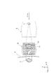
- FIG. 1 It is a side view which shows schematic structure of a neutron beam irradiation apparatus provided with the collimator which concerns on one Embodiment of this invention. It is a conceptual diagram which shows the state in which the neutron which passes the collimator of FIG. 1 is irradiated to the irradiation target of a to-be-irradiated body.
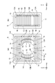
- A is a front view of a collimator
- (b) is a side view of a collimator.
- A) is a front view which shows the irradiation field and irradiation target which were formed with the leaf board
- (b) is sectional drawing along the IVB-IVB line
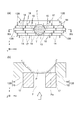
- A) is sectional drawing of the collimator which concerns on other embodiment of this invention, (b) is sectional drawing of the conventional collimator.
- the neutron beam irradiation apparatus 1 is a neutron capture therapy apparatus that irradiates a diseased part (irradiation target) T of a patient (irradiated body) P with a neutron beam.
- This neutron beam irradiation apparatus 1 is a boron neutron capture therapy (BNCT; Boron Neutron Capture Therapy) that selectively destroys cells in the affected area T by a nuclear reaction between boron (10B) previously incorporated as a compound in the affected area T and neutrons. ).
- BNCT Boron Neutron Capture Therapy
- the neutron beam irradiation apparatus 1 includes a moving table 2 on which a patient P is placed, a decelerating device 3 that decelerates neutrons, a target (neutron beam generating unit) 7 that generates neutrons, a moving table 2 and a decelerating device 3. And a collimator base (collimator support part) 4 provided therebetween. Further, the neutron beam irradiation apparatus 1 includes a CR system 8 for capturing an X-ray image of the affected part T of the patient P.
- the moving table 2 has a mounting table 2a on which the patient P sits.
- the mounting table 2a is configured such that the patient P can lie on the mounting table 2a by changing its shape.
- the movable table 2 has a vertical direction (vertical direction), a horizontal direction (horizontal direction, a direction close to and away from the speed reduction device 3), and a front-rear direction (horizontal direction perpendicular to the horizontal direction). It is movable.
- the target 7 generates neutrons by being irradiated with an ion beam (for example, proton beam) emitted from an accelerator (not shown).
- the speed reducer 3 decelerates neutrons generated at the target 7. Neutrons decelerated by the decelerator 3 are emitted to the patient P side.
- the shielding wall W is made of concrete or the like, and prevents unnecessary radiation to the patient P or the treatment room.
- the tip 3 a of the reduction gear 3 passes through the shielding wall W.
- the tip 3 a can enter the back side of the collimator base 4 when the collimator base 4 moves and approaches the speed reducer 3.
- the “back side” is the upstream side of the ion beam
- the “front side” is the patient P side.
- the collimator base 4 is provided with a collimator (neutron capture therapy collimator) 6 so as to protrude toward the movable base 2 side.
- This collimator 6 is for shaping the neutrons emitted from the reduction gear 3 into a predetermined shape (irradiation range) and taking out the neutrons in the irradiation direction Y.
- the collimator base 4 is movable in the front-rear direction.
- On the back surface of the collimator base 4 On the back surface of the collimator base 4, a recess for receiving the tip 3 a of the speed reducer 3 is formed.
- the collimator base 4 is used in a state in which the distal end portion 3a enters the recess on the back side.
- the mounting table 2a on which the patient P is mounted is brought close to the front surface side of the collimator table 4, and the collimator 6 is disposed so as to face the affected part T of the patient P.
- the collimator 6 sets an irradiation field F, which is an irradiation range of neutron beams, according to the region of the affected part T of the patient P.
- the collimator 6 has a rectangular parallelepiped outer shape.
- the collimator 6 includes a plurality of leaf plates 13 ⁇ / b> A and 13 ⁇ / b> B stacked in a vertical direction (first direction) Z orthogonal to the irradiation direction Y.
- the plurality of leaf plates 13A and 13B are arranged along the plate thickness direction.
- a plurality of leaf plates 13A and 13B may be arranged along the left-right direction X.
- Each of the leaf plates 13A and 13B is made of polyethylene containing lithium fluoride and has a rectangular plate shape.
- the plurality of leaf plates 13 ⁇ / b> A and 13 ⁇ / b> B are held in the collimator holder 11 to constitute a leaf plate group 13.
- a guide member (second direction support portion) 12 having a plurality of protrusions 16 for guiding the leaf plates 13A and 13B is disposed.
- the end portions in the irradiation direction Y of the leaf plates 13 ⁇ / b> A and 13 ⁇ / b> B that are in contact with the guide member 12 have an uneven shape that can be fitted to the protrusion 16 of the guide member 12.
- the leaf plates 13A (upper and lower four pieces in the example of FIG. 3) arranged at the upper end portion and the lower end portion of the leaf plate group 13 are divided into two in the left-right direction X. It is.
- the leaf plate 13B disposed in the intermediate portion excluding the upper end portion and the lower end portion of the leaf plate group 13 is composed of two divided leaf plates 14 and 15 per side divided in the left-right direction (second direction) X. Yes. More specifically, the divided leaf plate 14 and the divided leaf plate 15 are juxtaposed in the left-right direction X.
- the divided leaf plate 14 is disposed on the outer side (that is, closer to the collimator holder 11), and the divided leaf plate 15 is disposed on the inner side (that is, closer to the irradiation field F) adjacent to the divided leaf plate 14.
- the divided leaf plate 14 and the divided leaf plate 15 are integrally slidable in the left-right direction X. Since the leaf plate 13B can slide in the left-right direction X in this way, the shape and size of the irradiation field F can be arbitrarily set.
- the leaf plate 13A is not limited to being divided into two in the left-right direction X, and may be divided into four, for example.
- the divided leaf plate 15 of the leaf plate 13B is slidable in the irradiation direction Y.
- a protruding portion 17 that protrudes in the left-right direction X and extends in the irradiation direction Y is formed on the end surface of the divided leaf plate 15 that contacts the divided leaf plate 14.
- a groove portion (irradiation direction support portion) 18 extending in the irradiation direction Y direction is formed on the end face of the division leaf plate 14 that contacts the division leaf plate 15.
- the divided leaf plate 14 and the divided leaf plate 15 are each slidable in the irradiation direction Y in a state where the protruding portion 17 is fitted in the groove portion 18.
- the groove part 18 may function as a latching part which latches the edge part of the division
- the collimator 6 having the above configuration is a two-axis slide type multi-leaf collimator that is slidable in the left-right direction X and the irradiation direction Y.
- the outer shape of the leaf plate group 13 can be freely changed in the left-right direction X and the irradiation direction Y.
- the shape of the irradiated part is examined in advance, and the positions of the leaf plates 13A and 13B are adjusted so as to follow the shape.
- the positions of the leaf plates 13A and 13B are manually adjusted by the operator.
- the irradiation part of the patient P is brought close to the collimator 6 whose position has been adjusted, and neutron beams are irradiated toward the affected part T with a predetermined neutron dose.
- the irradiation field F can be accurately set for the affected part T. . Furthermore, since the divided leaf plate 15 of the leaf plate 13B can slide in the irradiation direction Y, the edge of the divided leaf plate 15 can be brought close to the body surface Pa of the patient P so as to follow the shape of the irradiated portion. it can. Thereby, the space
- Neutrons are relatively easy to dissipate.
- the gap between the body surface Pa of the patient P and the leaf plates 13A and 13B can be made as small as possible to block neutrons that are about to dissipate. Thereby, optimization of a neutron dose can be aimed at.
- the plurality of divided leaf plates 15 included in the leaf plate 13B can slide independently in the irradiation direction Y, for example, even when the irradiation site of the patient P is rounded in the left-right direction X,
- the divided leaves 14 and 15 can be slid in the irradiation direction Y to bring the edges of the leaf plates 14 and 15 closer to the body surface Pa of the irradiated region (see FIG. 4). This further suppresses neutron dissipation.
- FIG. 5A is a cross-sectional view of a collimator according to another embodiment
- FIG. 5B is a cross-sectional view of a conventional collimator.
- the leaf plate 23 of the collimator 20 shown in FIG. 5 (a) is different from the leaf plate 13B of the collimator 6 shown in FIG. 3 in that it has three divided leaf plates 24, 25, and 26 on one side.
- the corner portions on the opposite side to the patient P of each of the divided leaf plates 24 to 26 are cut away so that tapered portions 24a to 26a are formed on the respective divided leaf plates 24 to 26.
- the divided leaf plates 25, 26 excluding the divided leaf plate 24 are slidable in the irradiation direction Y.
- each of the divided leaf plates 24 to 26 has tapered portions 24a to 26a and the divided leaf plates 25 and 26 slide in the irradiation direction Y, so that neutrons are incident as a whole. You can take a wider direction.
- FIG. 5A shows a case where the affected part T (for example, a tumor) existing in the neck G of the patient P is irradiated with a neutron beam.
- the neck G of the patient P is between the jaw H and the shoulder E.
- the divergence of the divided leaf plates 25 and 26 so as to be in close contact with the body surface Pa of the patient P can prevent neutron dissipation from the gap between the body surface and the collimator 20.
- the basic role of the collimator is to cut off the radiation outside the irradiation area so that the exposure to normal tissues is negligible.
- Conventional radiation therapy for example, X-ray therapy or proton therapy
- X-ray therapy basically collimates radiation that is emitted from one point and travels straight in accordance with the irradiation area, and a flat collimator is several cm away from the surface of the irradiated body. Set it somewhere.
- neutrons most of them are scattered rays, whether they are reactors or accelerators, and those that fall in a collimator direction from a very large area compared to a collimator are used.
- neutrons it is a volume radiation source instead of a point radiation source, so the angle (solid angle) at which the collimator opening is viewed from the tumor is large, and conditions for increasing the dose rate that neutrons from a wider radiation source area can be used It becomes.
- neutron dissipation from the gap between the collimator and the surface of the irradiator can be prevented, it can be reflected in an increase in the dose rate of the component, and it can be avoided that the radiated neutrons are exposed outside the region.
- This increase in neutron utilization efficiency is one effect of the neutron collimators 6 and 20 according to the embodiment of the present invention.
- Another effect is to reduce the exposure of normal tissue by cutting off the area outside the irradiation area, and to consult the optimization of irradiation in consideration of the correlation between this reduction measure and the demand for an increase in the dose rate that conflicts. .
- the number of divided leaf plates is not limited to two or three, but may be four or more.
- Only the innermost (irradiation field F side) divided leaf plate may be slidable in the irradiation direction Y.
- the drive mechanism for example, a roller and a motor, or a piston can be used. The movement and positioning of the leaf plates 13A and 13B can be automated by the drive mechanism.
- the irradiation direction support portion may be 14 provided on the divided leaf plate 14, or a support mechanism may be provided as a separate member at the end of the divided leaf plate 14.
- the collimator base 4 may not be provided independently.
- a part that supports the collimator may be provided on the shielding wall W or the reduction gear 3.
- the present invention is not limited to BNCT using a boron compound, and may be applied to NCT using other elements.
- the present invention can be applied to a collimator used in a treatment method using a nuclear reaction between neutrons and gadolinium (157Gd or the like).
- a speed reducer is not necessary.
- the present invention is applicable to a neutron capture therapy collimator and a neutron capture therapy apparatus that can secure a neutron dose irradiated to an affected area per time and shorten the irradiation time.
- SYMBOLS 1 Neutron beam irradiation apparatus 6,20 ... Collimator, 13A, 13B ... Leaf board, 14, 15 ... Divided leaf board, 18 ... Groove part (irradiation direction support part), F ... Irradiation field (irradiation range), P ... Patient (Irradiated body), T ... affected area (irradiation target), X ... left-right direction (second direction), Y ... irradiation direction, Z ... up-down direction (first direction).
Abstract
Description
Claims (5)
- 被照射体における照射目標に合わせて中性子線の照射範囲を設定する中性子捕捉療法用コリメータであって、
中性子線の照射方向と直交する第1方向に重ねられた複数のリーフ板を備え、
複数の前記リーフ板のうち少なくとも一部のリーフ板は、前記照射方向に直交し且つ前記第1方向に直交する第2方向に沿ってスライド可能であると共に、前記照射方向にスライド可能であることを特徴とする中性子捕捉療法用コリメータ。 - 前記少なくとも一部のリーフ板は、前記第2方向に分割された複数の分割リーフ板を有し、
複数の前記分割リーフ板は、前記照射方向にそれぞれ独立してスライド可能であることを特徴とする請求項1記載の中性子捕捉療法用コリメータ。 - 被照射体における照射目標に合わせて中性子線の照射範囲を設定する中性子捕捉療法用コリメータであって、
中性子線の照射方向と直交する第1方向に複数枚重ねられると共に、複数枚のうち少なくとも一部は前記照射方向及び前記第1方向と直交する第2方向に少なくとも4つの分割リーフ板に分割されたリーフ板と、
前記リーフ板を第2方向に沿ってスライド可能に支持する第2方向支持部と、
前記第2方向に分割された分割リーフ板のうちの内側の分割リーフ板を前記照射方向に沿ってスライド可能に支持する照射方向支持部と、
を備えたことを特徴とする中性子捕捉療法用コリメータ。 - 前記照射方向支持部は、前記照射方向に沿ってスライド可能に支持された分割リーフ板に隣接する前記分割リーフ板に設けられると共に、前記照射方向に沿ってスライド可能に支持された分割リーフ板の端部を係止する係止部であることを特徴とする請求項3に記載の中性子捕捉療法用コリメータ。
- 中性子線を発生させる中性子線発生部と、
請求項1~4のいずれか一項に記載の中性子捕捉療法用コリメータと、
前記中性子捕捉療法用コリメータを支持するコリメータ支持部と、
を備えることを特徴とする中性子捕捉療法装置。
Priority Applications (3)
| Application Number | Priority Date | Filing Date | Title |
|---|---|---|---|
| CN201380005563.3A CN104053476B (zh) | 2012-03-30 | 2013-03-15 | 中子捕获疗法用准直器及中子捕获疗法装置 |
| EP13769074.9A EP2835149B1 (en) | 2012-03-30 | 2013-03-15 | Collimator for neutron capture therapy and neutron capture therapy apparatus |
| KR1020147019467A KR101441522B1 (ko) | 2012-03-30 | 2013-03-15 | 중성자 포착요법용 콜리메이터 및 중성자 포착요법장치 |
Applications Claiming Priority (2)
| Application Number | Priority Date | Filing Date | Title |
|---|---|---|---|
| JP2012080230A JP5630666B2 (ja) | 2012-03-30 | 2012-03-30 | 中性子捕捉療法用コリメータ及び中性子捕捉療法装置 |
| JP2012-080230 | 2012-03-30 |
Publications (1)
| Publication Number | Publication Date |
|---|---|
| WO2013146373A1 true WO2013146373A1 (ja) | 2013-10-03 |
Family
ID=49259634
Family Applications (1)
| Application Number | Title | Priority Date | Filing Date |
|---|---|---|---|
| PCT/JP2013/057485 WO2013146373A1 (ja) | 2012-03-30 | 2013-03-15 | 中性子捕捉療法用コリメータ及び中性子捕捉療法装置 |
Country Status (6)
| Country | Link |
|---|---|
| EP (1) | EP2835149B1 (ja) |
| JP (1) | JP5630666B2 (ja) |
| KR (1) | KR101441522B1 (ja) |
| CN (1) | CN104053476B (ja) |
| TW (1) | TWI486189B (ja) |
| WO (1) | WO2013146373A1 (ja) |
Cited By (2)
| Publication number | Priority date | Publication date | Assignee | Title |
|---|---|---|---|---|
| CN109499011A (zh) * | 2018-12-21 | 2019-03-22 | 苏州雷泰医疗科技有限公司 | 用于正交双层光栅装置的动态调强子野分割方法 |
| CN110548229A (zh) * | 2013-12-20 | 2019-12-10 | 梅维昂医疗系统股份有限公司 | 准直器和能量降能器 |
Families Citing this family (15)
| Publication number | Priority date | Publication date | Assignee | Title |
|---|---|---|---|---|
| TWI532056B (zh) | 2013-10-15 | 2016-05-01 | 財團法人工業技術研究院 | 濾屏與中子束源 |
| CN108325092B (zh) * | 2014-12-08 | 2020-08-07 | 南京中硼联康医疗科技有限公司 | 用于中子捕获治疗的射束整形体 |
| JP6430264B2 (ja) * | 2015-01-19 | 2018-11-28 | 住友重機械工業株式会社 | 負イオン源装置 |
| JP6565113B2 (ja) * | 2015-03-05 | 2019-08-28 | 住友重機械工業株式会社 | 中性子捕捉療法装置 |
| JP6566358B2 (ja) * | 2015-10-27 | 2019-08-28 | 住友重機械工業株式会社 | 中性子捕捉療法シミュレーションシステム及び中性子捕捉療法シミュレーション方法 |
| EP3566748B1 (en) * | 2017-06-05 | 2020-12-02 | Neuboron Medtech Ltd. | Beam shaping assembly for neutron capture therapy |
| US10446281B2 (en) * | 2017-08-15 | 2019-10-15 | Westinghouse Electric Company Llc | Detection apparatus and method of detecting the neutron absorption capability of a control element of a nuclear installation |
| CN109925613B (zh) * | 2017-12-18 | 2024-04-12 | 南京中硼联康医疗科技有限公司 | 中子捕获治疗装置 |
| CN109925611B (zh) * | 2017-12-18 | 2024-04-16 | 南京中硼联康医疗科技有限公司 | 中子捕获治疗装置 |
| JP7207856B2 (ja) * | 2018-03-12 | 2023-01-18 | 東芝Itコントロールシステム株式会社 | Ct撮影装置 |
| JP7082914B2 (ja) * | 2018-07-19 | 2022-06-09 | 住友重機械工業株式会社 | 中性子捕捉療法用のコリメータ、及び中性子線のコリメータの設置方法 |
| KR102118077B1 (ko) * | 2018-11-06 | 2020-06-02 | 한국원자력의학원 | 중성자 포획 치료시스템용 콜리메이터 |
| US20210265071A1 (en) * | 2020-02-26 | 2021-08-26 | Varian Medical Systems International Ag | Beam-blocking leaf and multileaf collimator containing same |
| CN111388881B (zh) * | 2020-03-23 | 2022-01-28 | 上海联影医疗科技股份有限公司 | 一种限束装置的控制方法以及系统 |
| CN115120895A (zh) * | 2022-08-31 | 2022-09-30 | 兰州大学 | 一种中子俘获辐照设备 |
Citations (4)
| Publication number | Priority date | Publication date | Assignee | Title |
|---|---|---|---|---|
| JP2002186676A (ja) * | 2000-12-22 | 2002-07-02 | Hitachi Medical Corp | 絞り装置および該絞り装置を用いた放射線治療装置 |
| JP2005185321A (ja) * | 2003-12-24 | 2005-07-14 | Toshiba Corp | コリメータ及び放射線治療装置及び放射線治療システム |
| JP2007195877A (ja) * | 2006-01-30 | 2007-08-09 | Mitsubishi Electric Corp | 粒子線治療装置 |
| JP2009189725A (ja) | 2008-02-18 | 2009-08-27 | Sumitomo Heavy Ind Ltd | 中性子線照射装置 |
Family Cites Families (8)
| Publication number | Priority date | Publication date | Assignee | Title |
|---|---|---|---|---|
| US4463266A (en) * | 1981-02-20 | 1984-07-31 | Instrument Ab Scanditronix | Neutron collimator |
| JPS59230199A (ja) * | 1983-06-14 | 1984-12-24 | 住友重機械工業株式会社 | 中性子線用コリメ−ト板 |
| US5818902A (en) * | 1996-03-01 | 1998-10-06 | Elekta Ab | Intensity modulated arc therapy with dynamic multi-leaf collimation |
| JP3779878B2 (ja) | 2001-01-30 | 2006-05-31 | 株式会社日立製作所 | マルチリーフコリメータ |
| JP4602366B2 (ja) | 2007-02-23 | 2010-12-22 | 株式会社日立製作所 | マルチリーフコリメータ |
| AU2008267660B2 (en) * | 2007-06-21 | 2011-06-16 | Nuctech Company Limited | Photoneutron conversion target and photoneutron X-ray source |
| EP2287636B1 (en) * | 2008-05-12 | 2019-10-23 | Tsinghua University | Method and system for inspecting special nuclear material |
| CN101757737B (zh) * | 2008-12-24 | 2012-11-14 | 住友重机械工业株式会社 | 多叶准直器以及放射线治疗装置 |
-
2012
- 2012-03-30 JP JP2012080230A patent/JP5630666B2/ja not_active Expired - Fee Related
-
2013
- 2013-03-15 CN CN201380005563.3A patent/CN104053476B/zh not_active Expired - Fee Related
- 2013-03-15 KR KR1020147019467A patent/KR101441522B1/ko active IP Right Grant
- 2013-03-15 WO PCT/JP2013/057485 patent/WO2013146373A1/ja active Application Filing
- 2013-03-15 EP EP13769074.9A patent/EP2835149B1/en not_active Not-in-force
- 2013-03-21 TW TW102106202A patent/TWI486189B/zh not_active IP Right Cessation
Patent Citations (4)
| Publication number | Priority date | Publication date | Assignee | Title |
|---|---|---|---|---|
| JP2002186676A (ja) * | 2000-12-22 | 2002-07-02 | Hitachi Medical Corp | 絞り装置および該絞り装置を用いた放射線治療装置 |
| JP2005185321A (ja) * | 2003-12-24 | 2005-07-14 | Toshiba Corp | コリメータ及び放射線治療装置及び放射線治療システム |
| JP2007195877A (ja) * | 2006-01-30 | 2007-08-09 | Mitsubishi Electric Corp | 粒子線治療装置 |
| JP2009189725A (ja) | 2008-02-18 | 2009-08-27 | Sumitomo Heavy Ind Ltd | 中性子線照射装置 |
Cited By (4)
| Publication number | Priority date | Publication date | Assignee | Title |
|---|---|---|---|---|
| CN110548229A (zh) * | 2013-12-20 | 2019-12-10 | 梅维昂医疗系统股份有限公司 | 准直器和能量降能器 |
| CN110548229B (zh) * | 2013-12-20 | 2022-04-19 | 梅维昂医疗系统股份有限公司 | 准直器和能量降能器 |
| CN109499011A (zh) * | 2018-12-21 | 2019-03-22 | 苏州雷泰医疗科技有限公司 | 用于正交双层光栅装置的动态调强子野分割方法 |
| CN109499011B (zh) * | 2018-12-21 | 2020-11-10 | 苏州雷泰医疗科技有限公司 | 用于正交双层光栅装置的动态调强子野分割方法 |
Also Published As
| Publication number | Publication date |
|---|---|
| CN104053476B (zh) | 2015-11-25 |
| KR101441522B1 (ko) | 2014-09-17 |
| TWI486189B (zh) | 2015-06-01 |
| EP2835149A4 (en) | 2015-10-21 |
| CN104053476A (zh) | 2014-09-17 |
| EP2835149B1 (en) | 2017-11-01 |
| TW201350166A (zh) | 2013-12-16 |
| EP2835149A1 (en) | 2015-02-11 |
| JP2013208257A (ja) | 2013-10-10 |
| KR20140093760A (ko) | 2014-07-28 |
| JP5630666B2 (ja) | 2014-11-26 |
Similar Documents
| Publication | Publication Date | Title |
|---|---|---|
| JP5630666B2 (ja) | 中性子捕捉療法用コリメータ及び中性子捕捉療法装置 | |
| JP6147296B2 (ja) | 中性子捕捉療法用ビーム整形アセンブリ | |
| JP2013208257A5 (ja) | ||
| CN108325092B (zh) | 用于中子捕获治疗的射束整形体 | |
| JP6652531B2 (ja) | 中性子ビーム源生成装置、および、そのフィルター | |
| JP2023002608A (ja) | 中性子捕捉療法用のビーム成形体 | |
| RU2717363C1 (ru) | Блок формирования пучка для нейтрон-захватной терапии | |
| JP6722281B2 (ja) | 中性子捕捉療法に用いられるビーム整形体 | |
| RU2707651C1 (ru) | Аппарат для нейтронной терапии | |
| JP6261919B2 (ja) | 中性子照射装置 | |
| JP5850362B2 (ja) | 中性子線照射装置および当該装置の作動方法 | |
| JP5791786B2 (ja) | 回転ガントリ及び粒子線治療装置 | |
| WO2018006550A1 (zh) | 中子治疗装置 | |
| WO2022037468A1 (zh) | 放射线照射系统及其控制方法 | |
| JP2013062193A (ja) | 中性子線照射装置 | |
| CN107569779B (zh) | 中子治疗装置 | |
| CN219814398U (zh) | 辐照系统及用于辐照系统的动物固定装置 | |
| TWI819931B (zh) | 放射線照射系統及其載置台控制方法 | |
| TWM549081U (zh) | 中子治療裝置 | |
| Balasubramanian et al. | Measurements of peripheral dose for multileaf collimator based linear accelerator | |
| US20230405360A1 (en) | Beam shaping device for boron neutron capture therapy apparatus, and boron neutron capture therapy apparatus comprising same | |
| JP2018143591A (ja) | 荷電粒子線治療装置 | |
| Zerby et al. | A COLLIMATOR STUDY FOR A 5-Gev ELECTRON BEAM |
Legal Events
| Date | Code | Title | Description |
|---|---|---|---|
| 121 | Ep: the epo has been informed by wipo that ep was designated in this application |
Ref document number: 13769074 Country of ref document: EP Kind code of ref document: A1 |
|
| ENP | Entry into the national phase |
Ref document number: 20147019467 Country of ref document: KR Kind code of ref document: A |
|
| REEP | Request for entry into the european phase |
Ref document number: 2013769074 Country of ref document: EP |
|
| WWE | Wipo information: entry into national phase |
Ref document number: 2013769074 Country of ref document: EP |
|
| NENP | Non-entry into the national phase |
Ref country code: DE |