WO2013146143A1 - 海水脱硫酸化処理装置及び海水排煙脱硫システム - Google Patents
海水脱硫酸化処理装置及び海水排煙脱硫システム Download PDFInfo
- Publication number
- WO2013146143A1 WO2013146143A1 PCT/JP2013/056128 JP2013056128W WO2013146143A1 WO 2013146143 A1 WO2013146143 A1 WO 2013146143A1 JP 2013056128 W JP2013056128 W JP 2013056128W WO 2013146143 A1 WO2013146143 A1 WO 2013146143A1
- Authority
- WO
- WIPO (PCT)
- Prior art keywords
- seawater
- upstream
- weir
- desulfurization
- oxidation
- Prior art date
Links
Images


Classifications
-
- B—PERFORMING OPERATIONS; TRANSPORTING
- B01—PHYSICAL OR CHEMICAL PROCESSES OR APPARATUS IN GENERAL
- B01D—SEPARATION
- B01D53/00—Separation of gases or vapours; Recovering vapours of volatile solvents from gases; Chemical or biological purification of waste gases, e.g. engine exhaust gases, smoke, fumes, flue gases, aerosols
- B01D53/14—Separation of gases or vapours; Recovering vapours of volatile solvents from gases; Chemical or biological purification of waste gases, e.g. engine exhaust gases, smoke, fumes, flue gases, aerosols by absorption
- B01D53/1456—Removing acid components
- B01D53/1481—Removing sulfur dioxide or sulfur trioxide
-
- B—PERFORMING OPERATIONS; TRANSPORTING
- B01—PHYSICAL OR CHEMICAL PROCESSES OR APPARATUS IN GENERAL
- B01D—SEPARATION
- B01D19/00—Degasification of liquids
- B01D19/0005—Degasification of liquids with one or more auxiliary substances
-
- B—PERFORMING OPERATIONS; TRANSPORTING
- B01—PHYSICAL OR CHEMICAL PROCESSES OR APPARATUS IN GENERAL
- B01D—SEPARATION
- B01D53/00—Separation of gases or vapours; Recovering vapours of volatile solvents from gases; Chemical or biological purification of waste gases, e.g. engine exhaust gases, smoke, fumes, flue gases, aerosols
- B01D53/34—Chemical or biological purification of waste gases
- B01D53/46—Removing components of defined structure
- B01D53/48—Sulfur compounds
- B01D53/50—Sulfur oxides
- B01D53/507—Sulfur oxides by treating the gases with other liquids
-
- C—CHEMISTRY; METALLURGY
- C02—TREATMENT OF WATER, WASTE WATER, SEWAGE, OR SLUDGE
- C02F—TREATMENT OF WATER, WASTE WATER, SEWAGE, OR SLUDGE
- C02F1/00—Treatment of water, waste water, or sewage
- C02F1/72—Treatment of water, waste water, or sewage by oxidation
- C02F1/74—Treatment of water, waste water, or sewage by oxidation with air
-
- F—MECHANICAL ENGINEERING; LIGHTING; HEATING; WEAPONS; BLASTING
- F23—COMBUSTION APPARATUS; COMBUSTION PROCESSES
- F23J—REMOVAL OR TREATMENT OF COMBUSTION PRODUCTS OR COMBUSTION RESIDUES; FLUES
- F23J15/00—Arrangements of devices for treating smoke or fumes
- F23J15/02—Arrangements of devices for treating smoke or fumes of purifiers, e.g. for removing noxious material
- F23J15/04—Arrangements of devices for treating smoke or fumes of purifiers, e.g. for removing noxious material using washing fluids
-
- B—PERFORMING OPERATIONS; TRANSPORTING
- B01—PHYSICAL OR CHEMICAL PROCESSES OR APPARATUS IN GENERAL
- B01D—SEPARATION
- B01D2252/00—Absorbents, i.e. solvents and liquid materials for gas absorption
- B01D2252/10—Inorganic absorbents
- B01D2252/103—Water
- B01D2252/1035—Sea water
-
- C—CHEMISTRY; METALLURGY
- C02—TREATMENT OF WATER, WASTE WATER, SEWAGE, OR SLUDGE
- C02F—TREATMENT OF WATER, WASTE WATER, SEWAGE, OR SLUDGE
- C02F2101/00—Nature of the contaminant
- C02F2101/10—Inorganic compounds
- C02F2101/101—Sulfur compounds
-
- C—CHEMISTRY; METALLURGY
- C02—TREATMENT OF WATER, WASTE WATER, SEWAGE, OR SLUDGE
- C02F—TREATMENT OF WATER, WASTE WATER, SEWAGE, OR SLUDGE
- C02F2103/00—Nature of the water, waste water, sewage or sludge to be treated
- C02F2103/08—Seawater, e.g. for desalination
-
- C—CHEMISTRY; METALLURGY
- C02—TREATMENT OF WATER, WASTE WATER, SEWAGE, OR SLUDGE
- C02F—TREATMENT OF WATER, WASTE WATER, SEWAGE, OR SLUDGE
- C02F2103/00—Nature of the water, waste water, sewage or sludge to be treated
- C02F2103/18—Nature of the water, waste water, sewage or sludge to be treated from the purification of gaseous effluents
-
- C—CHEMISTRY; METALLURGY
- C02—TREATMENT OF WATER, WASTE WATER, SEWAGE, OR SLUDGE
- C02F—TREATMENT OF WATER, WASTE WATER, SEWAGE, OR SLUDGE
- C02F2301/00—General aspects of water treatment
- C02F2301/04—Flow arrangements
- C02F2301/043—Treatment of partial or bypass streams
-
- F—MECHANICAL ENGINEERING; LIGHTING; HEATING; WEAPONS; BLASTING
- F23—COMBUSTION APPARATUS; COMBUSTION PROCESSES
- F23J—REMOVAL OR TREATMENT OF COMBUSTION PRODUCTS OR COMBUSTION RESIDUES; FLUES
- F23J2215/00—Preventing emissions
- F23J2215/20—Sulfur; Compounds thereof
-
- F—MECHANICAL ENGINEERING; LIGHTING; HEATING; WEAPONS; BLASTING
- F23—COMBUSTION APPARATUS; COMBUSTION PROCESSES
- F23J—REMOVAL OR TREATMENT OF COMBUSTION PRODUCTS OR COMBUSTION RESIDUES; FLUES
- F23J2217/00—Intercepting solids
- F23J2217/50—Intercepting solids by cleaning fluids (washers or scrubbers)
-
- F—MECHANICAL ENGINEERING; LIGHTING; HEATING; WEAPONS; BLASTING
- F23—COMBUSTION APPARATUS; COMBUSTION PROCESSES
- F23J—REMOVAL OR TREATMENT OF COMBUSTION PRODUCTS OR COMBUSTION RESIDUES; FLUES
- F23J2900/00—Special arrangements for conducting or purifying combustion fumes; Treatment of fumes or ashes
- F23J2900/15041—Means for absorbing SOx using seawater
Definitions
- the present invention relates to wastewater treatment of flue gas desulfurization devices applied to power plants such as coal-fired, crude oil-fired, and heavy oil-fired, and more particularly, wastewater of exhaust gas desulfurization devices that use the seawater method (used seawater).
- the present invention relates to a drainage water channel and a seawater flue gas desulfurization system of a seawater desulfurization apparatus that introduces a gas into an aeration apparatus.
- combustion exhaust gas (hereinafter referred to as “exhaust gas”) discharged from a boiler is sulfur such as sulfur dioxide (SO 2 ) contained in the exhaust gas.
- SO 2 sulfur dioxide
- SOx oxide
- the flue gas desulfurization apparatus (hereinafter referred to as “seawater flue gas desulfurization apparatus”) employing the seawater method is a desulfurization system that uses seawater as an absorbent.
- a desulfurization tower (absorption tower) having a cylindrical shape or a rectangular shape such as a substantially cylindrical shape
- the seawater is used as an absorbing liquid to make a wet-based gas-liquid contact. Is generated to remove sulfur oxides.
- the desulfurized seawater (spent seawater) used as the absorbent in the desulfurization tower described above is, for example, a part of the water channel when drained by flowing in a long water channel (Seawater Oxidation Treatment System; SOTS) with an open top.
- SOTS Seawater Oxidation Treatment System
- seawater desulfurization requires an enormous amount of seawater, a compact seawater desulfurization device is desired.
- an object of the present invention is to provide a seawater desulfation treatment apparatus and a seawater flue gas desulfurization system that achieve a compact system.
- the first invention of the present invention for solving the above-described problem is an acidic desulfurization containing sulfurous acid (H 2 SO 3 ) produced by seawater desulfurization of, for example, sulfur oxide in boiler exhaust gas by a seawater desulfurization apparatus.
- H 2 SO 3 sulfurous acid
- a seawater desulfation treatment apparatus comprising an oxidation / aeration tank for performing water quality recovery treatment with diluted seawater and air, and having an upstream weir formed on the inlet side in the longitudinal direction of the oxidation / aeration tank A main flow path into which the diluted seawater is introduced; an upstream mixing section that is formed on the upstream side of the upstream weir, and that mixes with the diluted seawater while introducing the acidic desulfurized seawater; and the oxidation / aeration tank A sub-flow path for supplying diluted seawater that is diverted from the upstream side of the upstream-side mixing section and that is deoxidized and aerated in the oxidation / aeration tank. It is in the desulfation treatment equipment.
- a downstream side weir is formed on the outlet side in the longitudinal direction of the oxidation / aeration tank and secures the volume of the water quality recovery seawater to a predetermined amount or more together with the upstream side weir It exists in the seawater desulfation processing apparatus characterized by this.
- the diluted seawater that is provided downstream of the downstream weir and bypasses the sub-flow path is mixed with water quality recovery seawater on the downstream side of the downstream weir. It exists in the seawater desulfation processing apparatus characterized by having the downstream mixing part which carries out post-dilution.
- the fourth invention is the seawater desulfation treatment apparatus according to the first invention, wherein an opening is formed in the upstream weir.
- the seawater desulfation apparatus according to the second aspect, wherein the openings of the upstream weir and the downstream weir are variable.
- the sixth invention is the seawater desulfation treatment apparatus according to the second invention, wherein heights of the upstream weir and the downstream weir are adjustable.
- the seventh invention is the seawater desulfation treatment apparatus according to the first invention, wherein the upstream weir is multistage, and the height thereof is lowered as going downstream.
- a flue gas desulfurization absorption tower in which exhaust gas and desulfurization seawater are brought into gas-liquid contact to desulfurize sulfur oxide (SO x ) in the gas to sulfurous acid (H 2 SO 3 ), 7.
- the seawater desulfation treatment apparatus according to any one of 7 is provided, and the pumped seawater is branched into diluted seawater and desulfurization seawater, and desulfurization is performed in the flue gas desulfurization absorption tower using the branched desulfurization seawater.
- the acidic desulfurized seawater is introduced into the upstream mixing portion of the seawater desulfation treatment apparatus, and the diluted seawater is supplied to the main flow path and the sub flow path of the seawater desulfation treatment apparatus at a predetermined ratio.
- the seawater flue gas desulfurization system which is characterized by introducing.
- the acidic desulfurized seawater from the desulfurization apparatus is introduced into the upstream side mixing section, and predilution mixing is ensured by the diluted seawater in this section.
- the reliably mixed acidic desulfurized seawater passes over the upstream weir and flows into the oxidation / aeration tank, so that it is aerated in the oxidation / aeration tank, and the oxidation / aeration process is performed reliably.
- the acidic desulfurized seawater that has been reliably oxidized and aerated is subjected to final dilution with diluted seawater bypassed by the secondary flow path, and then discharged into the sea as discharged seawater.
- FIG. 1 is a schematic diagram of a seawater desulfation treatment apparatus according to the present embodiment.
- FIG. 2 is a schematic diagram of another seawater desulfation treatment apparatus according to the present embodiment.
- 3 is a cross-sectional view taken along line AA in FIG.
- FIG. 4 is a cross-sectional view taken along line AA of FIG. 1 according to another embodiment.
- FIG. 5 is a schematic diagram of another seawater desulfation treatment apparatus according to the present embodiment.
- FIG. 6A is a schematic diagram of another seawater desulfation treatment apparatus according to the present embodiment.
- FIG. 6B is a schematic diagram of another seawater desulfation treatment apparatus according to the present embodiment.
- FIG. 7 is a schematic view of another seawater desulfation treatment apparatus according to the present embodiment.
- FIG. 1 is a schematic diagram of a seawater desulfation treatment apparatus according to the present embodiment.
- FIG. 2 is a schematic diagram of another seawater desulfation treatment apparatus according to the present
- FIG. 8 is a schematic view of the movable weir of the present embodiment.
- FIG. 9A is a schematic diagram of the movable weir of the present embodiment.
- FIG. 9-2 is a schematic view of the movable weir of the present embodiment.
- FIG. 10 is a schematic view of a modified example of the weir according to the present embodiment.
- FIG. 11 is a schematic view of a seawater flue gas desulfurization system including the seawater desulfation treatment apparatus shown in FIG.
- FIG. 12 is a graph showing the relationship between the distance between the oxidation / aeration tank and the pH of the seawater.
- FIGS. 1 and 3 are schematic views of a seawater desulfation treatment apparatus according to the present embodiment.
- 3 and 4 are sectional views taken along line AA in FIGS.
- or FIG. 7 is the schematic of the other seawater desulfation processing apparatus which concerns on a present Example.
- a seawater desulfation treatment apparatus 10A according to the present embodiment is generated by desulfurizing, for example, sulfur oxides in boiler exhaust gas using a seawater desulfurization apparatus (not shown).
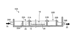
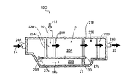
- a seawater desulfation treatment apparatus comprising an oxidation / aeration tank 16 for performing water quality recovery treatment on acidic desulfurized seawater 13 containing sulfurous acid (H 2 SO 3 ) using diluted seawater 14 and air 15, which is an oxidation / aeration tank 16 has an upstream weir 21A formed on the inlet side in the longitudinal direction, and is formed on the upstream side of the main flow path 20A into which the diluted seawater 14 is introduced and the upstream weir 21A, while introducing the acid desulfurized seawater 13 Acid desulfurized seawater (aerated seawater) detoured from the upstream side of the upstream mixing unit 22A for mixing with the diluted seawater 14 and upstream of the upstream mixing unit 22A of the oxidation / aeration tank 16 and oxidized and aerated in the oxidation / aeration tank 16 13) after A sub-passage 20B for supplying dilution seawater 14 dilution is made comprises a
- reference numeral 24 ⁇ / b> A denotes a diluted seawater introduction passage
- 24 ⁇ / b> B denotes a discharge seawater discharge passage
- 27 denotes a partition that separates the main flow path 20 ⁇ / b> A and the sub flow path 20 ⁇ / b> B.
- an inlet weir 25A and an outlet weir 25B are provided on the upstream side of the upstream weir 21A and the downstream side of the downstream weir 21B, respectively.
- a section sandwiched between the upstream side of the upstream weir 21A and the inlet weir 25A is the upstream mixing section 22A, and a section sandwiched between the downstream weir 21B and the outlet weir 25B is the downstream mixing section 22B.
- An acid desulfurized seawater introduction passage 26 through which the acid desulfurized seawater 13 is introduced is provided on the side wall of the upstream mixing unit 22A. Then, the acidic desulfurized seawater 13 is introduced into the upstream mixing portion 22A through the acidic desulfurized seawater introduction passage 26, and predilution mixing is reliably performed by the diluted seawater 14 in this section.
- the desulfurized seawater is supplied to the flue gas desulfurization absorption tower using a liquid feed pump (not shown).
- the desulfurized seawater can be installed in a section of the upstream mixing unit 22A. Further, it may be installed on the upstream side of the diluted seawater introduction passage 24A.
- the diluted seawater 14b in which a part of the diluted seawater 14 is detoured by the sub-channel 20B is post-diluted into the acid-desulfurized seawater (aerated seawater) 13 which is introduced into the downstream side mixing unit 22B and oxidized and aerated here. Finished dilution is performed, and then discharged into the sea as discharged seawater 25.
- An aeration pipe 28 for diffusing air is installed at the bottom of the oxidation / aeration tank 16, but this oxidation / aeration area is reliably divided by the upstream weir 21A and the downstream weir 21B. Oxidative aeration of the acidic desulfurized seawater 13 with a predetermined volume of seawater is ensured.
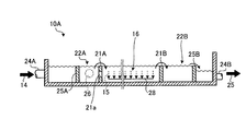
- the lateral width of the flow path is narrowed on the introduction side of the diluted seawater 14 and the discharge side of the discharged seawater 25, but the present invention is limited to this.
- the width may be the same as the total width of the main flow path 20A and the sub flow path 20B.
- the amount of absorbed SO 2 in the exhaust gas that absorbs sulfur oxide in the exhaust gas ( ⁇ S) is supplied to the main channel seawater amount (total seawater amount (F T ) ⁇ subchannels introduced into the main channel 20A.
- the value ( ⁇ ) divided by the amount of seawater (F B )) to be controlled is in the range of 0.5 to 1.3.
- 0.5 ⁇ ( ⁇ S / (F T ⁇ F B )) ⁇ ⁇ 1.3
- F T is the total seawater volume
- the amount of absorbed SO 2 ( ⁇ S) is 70,000 gmol / h and the total amount of seawater is 100,000 m 3 / h
- the dilution supplied to the secondary flow path 20B The amount of seawater in the seawater 14b may be 30,000 m 3 / h.
- the absorption SO 2 ( ⁇ S) changes (rises) unexpectedly.
- an opening 21 a may be provided in a part of the upstream weir 21 ⁇ / b> A so that the mixed seawater promotes the inflow into the oxidation / aeration tank 16.
- the opening area of the opening 21a may be variable, and the cross-sectional area of the flow path may be adjusted.
- an upstream mixing unit 22A and a downstream mixing unit 22B are provided on the upstream side and the downstream side of the oxidation / aeration tank 16, respectively.
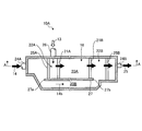
- the present invention is not limited to this, and only the upstream mixing unit 22A may be provided as in the seawater desulfation treatment apparatus 10B shown in FIG.
- the flow rate of the diluted seawater 14b supplied to the sub-channel 20B can be adjusted by a pump (not shown), but the seawater desulfation treatment shown in FIG.
- the movable sluice 29A provided on the partition inlet side 27a of the partition wall 27 as in the device 10C, the distribution amount of the diluted seawater 14 can be adjusted.
- the movable sluice 29 has a guide portion 29a and is movable in the vertical direction.
- the sub-channel weir 30 may be installed in the sub-channel 20B, and the flow rate of the diluted seawater 14b passing through the sub-channel 20B may be adjusted.
- the movable sluice that is movable in the vertical direction as shown in FIG. 6A is not limited to the movable sluice, which is movable in the vertical direction.
- the seawater desulfation treatment apparatus 10C shown in FIG. It is also possible to adjust the distribution amount of the diluted seawater 14 by providing a rotating sluice 29B that rotates and adjusting the degree of opening and closing.
- diluted seawater 14b is introduced from the partition wall outlet side 27b after passing through the partition wall 27, and the final dilution is performed.
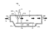
- the present invention is not limited to this, and an opening 27c may be provided in the partition wall 27 as in the seawater desulfation apparatus 10D shown in FIG.
- a part of the diluted seawater 14b supplied to the auxiliary flow path 20B through the opening 27c may be introduced into the oxidation / aeration tank 16 to dilute the oxidized / aerated aeration seawater.
- a part means the remaining seawater which has secured a necessary amount in the downstream mixing unit 22B.
- FIG. 12 shows the relationship between the distance between the oxidation / aeration tank and the pH of the seawater.
- the horizontal axis indicates the distance from the inlet of the oxidation / aeration tank 16, and the vertical axis indicates the pH of the seawater.
- the pH of the graph rapidly increases as the distance increases, indicating a portion where the downstream mixing unit 22 is mixing with the diluted seawater 14 b bypassed by the sub-flow path 20 ⁇ / b> B.
- the “solid line” indicates a case where the amount of bypass is small and ⁇ is small, and the pH at the oxidation tank inlet is high, but the pH drop due to oxidation of sulfurous acid is small.
- the weir of the downstream side weir 21B is a movable weir and can be adjusted by adjusting its height.
- an opening may be provided in the downstream weir 21B, and the opening may be made variable to adjust the flow passage cross-sectional area of the opening.
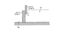
- FIG. 8 is a schematic view of the movable weir of the present embodiment. As shown in FIG. 8, this movable weir is connected to the foundation wall 21A-1 (21B-1) erected from the bottom 16a of the oxidation / aeration tank 16 and the foundation wall 21A-1 (21B-1). The movable wall 21A-2 (21B-2) can be moved up and down freely. In addition, since the movable weir of the downstream side weir 21B is the same, a code
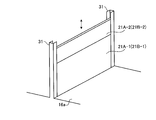
- FIGS. 9-1 and 9-2 are schematic views of other movable weirs in this embodiment.
- the movable weir shown in FIG. 9-1 includes a pair of U-shaped guide members 31 erected from the bottom 16a of the oxidation / aeration tank 16, and an upstream weir that is movable in the vertical direction within the guide member 31. 21A (downstream dam 21B) is inserted, and the flow rate is adjusted as necessary.
- the movable weir shown in FIG. 9-2 includes a pair of U-shaped guide members 31 erected from the bottom portion 16a of the oxidation / aeration tank 16, and a single piece movable in the guide member 31 in the vertical direction.
- the movable upstream weir 21A is divided into two parts (21A-1, 21A-2) and inserted, and the movable amount is adjusted so that the flow rate is adjusted as necessary. Note that only the upper weir 21A-2 may be movable by fixing the lower weir 21A-1.
- the movable weir of the downstream side weir 21B is the same, a code
- the volume in the oxidation / aeration tank 16 can be arbitrarily changed.
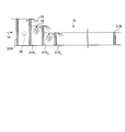
- FIG. 10 is a schematic diagram of another modification of the weir according to the present embodiment.
- a plurality of upstream weirs 21 ⁇ / b> A installed on the upstream side of the oxidation / aeration tank 16 toward the downstream side of the flow of the diluted seawater 14 (three in this embodiment) 21 ⁇ / b > A 1 , 21 ⁇ / b > A 2 , 21A 3 is erected, and the height of the weir is gradually decreased from the upstream side weir 21A 1 to the downstream side weir 21A 3 so that it falls as a waterfall 33.
- the height of the weir is gradually decreased from the upstream side weir 21A 1 to the downstream side weir 21A 3 so that it falls as a waterfall 33.
- innumerable fine air bubbles 34 are generated in the seawater falling in the waterfall, increasing the seawater surface area in contact with the air, and the entrainment effect is exerted, making it easy to absorb external air in the oxidation / aeration tank 16. I am doing so.
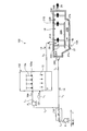
- FIG. 11 is a schematic view of a seawater flue gas desulfurization system including the seawater desulfation treatment apparatus shown in FIG.
- the seawater flue gas desulfurization system 100 includes a flue gas desulfurization absorption tower 102 that causes gas-liquid contact between the exhaust gas 101 and the seawater 14a for desulfurization to desulfurize SO 2 to sulfurous acid (H 2 SO 3 ).
- a seawater desulfurization treatment apparatus 10A provided on the downstream side of the flue gas desulfurization absorption tower 102 and provided with an oxidation / aeration tank 16 for diluting and mixing the acidic desulfurized seawater 13 containing sulfur with the diluted seawater 14.
- the seawater pumped from the ocean is branched into diluted seawater 14 and desulfurization seawater 14a, and desulfurized in the flue gas desulfurization absorption tower 102 using the branched desulfurization seawater 14a, and then the acidic desulfurization seawater.
- reference numeral 110 is a condenser for cooling seawater
- L 1 is a seawater pumping passage
- L 2 is a diluted seawater supply passage
- L 3 is a seawater supply passage for desulfurization
- L 4 is an exhaust gas supply passage
- L 5 is acidic.
- Desulfurized seawater supply passages P 1 and P 2 are seawater pumps.
- desulfurization seawater 14a supplied through the desulfurization seawater supply passage L 3 is injected upward from the aeration tube 102a, and the injected desulfurization seawater 14a and the exhaust gas 101 was To make SO 2 in the exhaust gas 101 absorbed in seawater.
- the acidic desulfurized seawater 13 that has absorbed sulfur in the flue gas desulfurization absorption tower 102 is stored at the bottom of the flue gas desulfurization absorption tower 102, and then the seawater desulfation treatment apparatus provided on the downstream side of the flue gas desulfurization absorption tower 102.
- the upstream mixing section 22A of 10A is introduced via the acid desulfurization seawater supply passage L 5, wherein securely mixed with diluted seawater 14 supplied from the dilution seawater supply passage L 2 is made.
- the mixed and diluted acidic desulfurized seawater 13 is introduced into the oxidation / aeration tank 16 provided on the downstream side of the upstream mixing unit 22A beyond the upstream weir 21A.
- air supplied from an oxidation air blower (not shown) is supplied through the air diffuser 102 a, and the quality of the acid desulfurized seawater 13 is recovered.
- the diluted seawater 14b which is separately bypassed in the downstream side mixing section 22B beyond the downstream weir 21B, is introduced into the diluted seawater 14b from the partition wall outlet side 27b, and post-dilution is performed to complete the final dilution. Thereafter, it is discharged to the sea as discharged seawater 25 through the discharged seawater discharge passage 24B.
Abstract
ボイラ排ガス中の硫黄酸化物を海水脱硫することで生成される亜硫酸(H2SO3)を含んだ酸性脱硫海水13を、希釈海水14及び空気により水質回復処理を行う酸化・曝気槽16を備えた海水脱硫酸化処理装置であって、酸化・曝気槽16の長手方向の入口側に形成された上流側堰21Aを有し、希釈海水14が導入される主流路20Aと、上流側堰21Aの上流側に形成され、酸性脱硫海水13を導入しつつ、前記希釈海水14と混合する上流側混合部22Aと、酸化・曝気槽16の上流側混合部22Aの上流側から迂回され、前記酸化・曝気槽16で酸化曝気された酸性脱硫海水13を、後希釈する希釈海水14を供給する副流路20Bと、を具備してなる。
Description
本発明は、石炭焚き、原油焚き及び重油焚き等の発電プラントに適用される排煙脱硫装置の排水処理に係り、特に、海水法を用いて脱硫する排煙脱硫装置の排水(使用済海水)をエアレーション装置に導入する海水脱硫装置の排水水路及び海水排煙脱硫システムに関する。
従来、石炭や原油等を燃料とする発電プラントにおいて、ボイラから排出される燃焼排気ガス(以下、「排ガス」と呼ぶ)は、該排ガス中に含まれている二酸化硫黄(SO2)等の硫黄酸化物(SOx)を除去してから大気に放出される。このような脱硫処理を施す排煙脱硫装置の脱硫方式としては、石灰石膏法、スプレードライヤー法及び海水法等が知られている。
このうち、海水法を採用した排煙脱硫装置(以下、「海水排煙脱硫装置」と呼ぶ)は、吸収剤として海水を使用する脱硫方式である。この方式では、たとえば略円筒のような筒形状又は角形状を縦置きにした脱硫塔(吸収塔)の内部に海水及びボイラ排ガスを供給することにより、海水を吸収液として湿式ベースの気液接触を生じさせて硫黄酸化物を除去している。
上述した脱硫塔内で吸収剤として使用した脱硫後の海水(使用済海水)は、たとえば、上部が開放された長い水路(Seawater Oxidation Treatment System;SOTS)内を流れ排水される際、水路の一部の底面に設置したエアレーション装置(酸化・曝気槽)から微細気泡を流出させるエアレーションによって脱炭酸(爆気)される(特許文献1~3)。
上述した脱硫塔内で吸収剤として使用した脱硫後の海水(使用済海水)は、たとえば、上部が開放された長い水路(Seawater Oxidation Treatment System;SOTS)内を流れ排水される際、水路の一部の底面に設置したエアレーション装置(酸化・曝気槽)から微細気泡を流出させるエアレーションによって脱炭酸(爆気)される(特許文献1~3)。
しかしながら、海水脱硫には膨大な海水量が必要となるので、海水脱硫装置のコンパクト化が切望されている。
本発明は、前記問題に鑑み、システムのコンパクト化を図った海水脱硫酸化処理装置及び海水排煙脱硫システムを提供することを課題とする。
上述した課題を解決するための本発明の第1の発明は、海水脱硫装置により例えばボイラ排ガス中の硫黄酸化物を海水脱硫することで生成される亜硫酸(H2SO3)を含んだ酸性脱硫海水を、希釈海水及び空気により水質回復処理を行う酸化・曝気槽を備えた海水脱硫酸化処理装置であって、前記酸化・曝気槽の長手方向の入口側に形成された上流側堰を有し、前記希釈海水が導入される主流路と、前記上流側堰の上流側に形成され、前記酸性脱硫海水を導入しつつ、前記希釈海水と混合する上流側混合部と、前記酸化・曝気槽の上流側混合部の上流側から迂回され、前記酸化・曝気槽で酸化曝気された酸性脱硫海水を、後希釈する希釈海水を供給する副流路と、を具備してなることを特徴とする海水脱硫酸化処理装置にある。
第2の発明は、第1の発明において、前記酸化・曝気槽の長手方向の出口側に形成され、前記上流側堰と共に、水質回復海水の容積を所定量以上に確保する下流側堰を有することを特徴とする海水脱硫酸化処理装置にある。
第3の発明は、第2の発明において、前記下流側堰の下流側に設けられ、副流路を迂回した希釈海水を用いて下流側堰の後流側で、水質回復海水と混合して後希釈する下流側混合部を有することを特徴とする海水脱硫酸化処理装置にある。
第4の発明は、第1の発明において、前記上流側堰に開口が形成されていることを特徴とする海水脱硫酸化処理装置にある。
第5の発明は、第2の発明において、前記上流側堰及び下流側堰の開口が可変自在であることを特徴とする海水脱硫酸化処理装置にある。
第6の発明は、第2の発明において、前記上流側堰及び下流側堰の高さが調節自在であることを特徴とする海水脱硫酸化処理装置にある。
第7の発明は、第1の発明において、前記上流側堰が多段であり、下流側に行くにつれて、その高さを低くしてなることを特徴とする海水脱硫酸化処理装置にある。
第8の発明は、排ガスと脱硫用海水とを気液接触してガス中の硫黄酸化物(SOX)を亜硫酸(H2SO3)へ脱硫反応させる排煙脱硫吸収塔と、第1乃至7のいずれか一つの海水脱硫酸化処理装置とを具備してなり、汲み上げた海水を希釈海水と、脱硫用海水とに分岐し、分岐した脱硫用海水を用いて前記排煙脱硫吸収塔で脱硫した後、前記酸性脱硫海水として、前記海水脱硫酸化処理装置の上流側混合部へ導入すると共に、前記希釈海水を、前記海水脱硫酸化処理装置の前記主流路と前記副流路とに所定割合で導入することを特徴とする海水排煙脱硫システムにある。
本発明によれば、脱硫装置からの酸性脱硫海水は、上流側混合部内に導入され、この区画内で希釈海水により前希釈の混合が確実になされる。この確実に混合された酸性脱硫海水は、上流側堰を越えて、酸化・曝気槽に流入されることにより、酸化・曝気槽内にて曝気され、酸化曝気処理が確実になされる。酸化曝気処理が確実になされた酸性脱硫海水は、副流路により迂回された希釈海水により仕上げ希釈がなされ、その後放流海水として海へ放流される。
以下、この発明につき図面を参照しつつ詳細に説明する。なお、この実施例により本発明が限定されるものではなく、また、実施例が複数ある場合には、各実施例を組み合わせて構成するものも含むものである。また、下記実施例における構成要素には、当業者が容易に想定できるもの、あるいは実質的に同一のものが含まれる。
本発明による実施例に係る海水脱硫酸化処理装置について、図面を参照して説明する。図1乃至図3は、本実施例に係る海水脱硫酸化処理装置の概略図である。図3及び図4は、図1及び図2のA-A線断面図である。また図5乃至図7は、本実施例に係る他の海水脱硫酸化処理装置の概略図である。
先ず、図1及び図3に示すように、本実施例に係る海水脱硫酸化処理装置10Aは、海水脱硫装置(図示せず)により例えばボイラ排ガス中の硫黄酸化物を海水脱硫することで生成される亜硫酸(H2SO3)を含んだ酸性脱硫海水13を、希釈海水14及び空気15により水質回復処理を行う酸化・曝気槽16を備えた海水脱硫酸化処理装置であって、酸化・曝気槽16の長手方向の入口側に形成された上流側堰21Aを有し、希釈海水14が導入される主流路20Aと、上流側堰21Aの上流側に形成され、酸性脱硫海水13を導入しつつ、前記希釈海水14と混合する上流側混合部22Aと、酸化・曝気槽16の上流側混合部22Aの上流側から迂回され、前記酸化・曝気槽16で酸化曝気された酸性脱硫海水(曝気海水)13を、後希釈する希釈海水14を供給する副流路20Bと、を具備してなるものである。
図1中、符号24Aは希釈海水導入通路、24Bは放流海水排出通路、27は主流路20Aと副流路20Bとを隔てる隔壁を図示する。
本実施例では、上流側堰21Aの上流側と、下流側堰21Bの下流側とに、各々入口部堰25A及び出口部堰25Bを設けている。
そして、上流側堰21Aの上流側と入口部堰25Aとで挟まれる区画を上流側混合部22Aとすると共に、下流側堰21Bと出口部堰25Bとで挟まれる区画を下流側混合部22Bとしている。
そして、上流側堰21Aの上流側と入口部堰25Aとで挟まれる区画を上流側混合部22Aとすると共に、下流側堰21Bと出口部堰25Bとで挟まれる区画を下流側混合部22Bとしている。
上流側混合部22Aの側壁には酸性脱硫海水13が導入される酸性脱硫海水導入通路26が設けられている。
そして、酸性脱硫海水13は、この酸性脱硫海水導入通路26により、上流側混合部22A内に導入され、この区画内で希釈海水14により前希釈の混合が確実になされる。
そして、酸性脱硫海水13は、この酸性脱硫海水導入通路26により、上流側混合部22A内に導入され、この区画内で希釈海水14により前希釈の混合が確実になされる。
このように希釈海水14と確実に混合された酸性脱硫海水13が、上流側堰21Aを越えて、酸化・曝気槽16に流入される。これにより、酸化・曝気槽16内にて散気管28より供給される空気15による酸化・曝気処理が確実となる。
なお、脱硫海水は、図示しない送液ポンプを用いて、排煙脱硫吸収塔へ供給しているが、例えば上流側混合部22Aの区画内に設置することができる。また、希釈海水導入通路24Aの前流側に設置するようにしてもよい。
なお、脱硫海水は、図示しない送液ポンプを用いて、排煙脱硫吸収塔へ供給しているが、例えば上流側混合部22Aの区画内に設置することができる。また、希釈海水導入通路24Aの前流側に設置するようにしてもよい。
また、希釈海水14の一部を副流路20Bにより迂回された希釈海水14bは、下流側混合部22Bに導入され、ここで酸化曝気された酸性脱硫海水(曝気海水)13の後希釈である仕上げ希釈がなされ、その後放流海水25として海へ放流されている。
酸化・曝気槽16の底部には空気を散気させる散気管28が設置されているが、この酸化・曝気領域を上流側堰21Aと、下流側堰21Bとで確実に区分けしているので、所定容積の海水による酸性脱硫海水13の酸化曝気が確実になされる。
ここで、図1に示す海水脱硫酸化処理装置10Aでは、希釈海水14の導入側と放流海水25の排出側において、流路の横幅を狭くしているが、本発明はこれに限定されるものではなく、例えば図2に示すように、主流路20Aと副流路20Bとの合計の幅と同一の幅としても良い。
本発明では、排ガス中の硫黄酸化物を吸収する排ガス中の吸収SO2量(ΔS)を、主流路20Aに導入される主流路海水量(全海水量(FT)-副流路に供給する海水量(FB))で除した値(αとする)が0.5~1.3の範囲で制御するようにしている。
0.5<(ΔS/(FT-FB))=α<1.3
ここで、FTは、全海水量、FBは副流路20Bへ供給する海水量である。
より好適には、0.65<(ΔS/(FT-FB))=α<1.15の範囲で制御することで、最適希釈海水量を確実に制御するようにしている。
0.5<(ΔS/(FT-FB))=α<1.3
ここで、FTは、全海水量、FBは副流路20Bへ供給する海水量である。
より好適には、0.65<(ΔS/(FT-FB))=α<1.15の範囲で制御することで、最適希釈海水量を確実に制御するようにしている。
例えば吸収SO2量(ΔS)が70,000gmol/hの際に、全海水量が100,000m3/hの場合、αを1.0で制御しようとすると、副流路20Bに供給する希釈海水14bの海水量は30,000m3/hとすれば良いこととなる。
これにより、例えばボイラ負荷等により排ガス中の硫黄酸化物の量が増大した際、吸収SO2(ΔS)は予想外に変化(上昇)するが、このような場合には、副流路20Bに供給する希釈海水14bの海水量を少なくして、酸化・曝気槽16での酸化・曝気を確実に行うことが可能となる。
これにより、例えばボイラ負荷等により排ガス中の硫黄酸化物の量が増大した際、吸収SO2(ΔS)は予想外に変化(上昇)するが、このような場合には、副流路20Bに供給する希釈海水14bの海水量を少なくして、酸化・曝気槽16での酸化・曝気を確実に行うことが可能となる。
また、図4に示すように、上流側堰21Aの一部に開口21aを設け、混合海水が、酸化・曝気槽16内への流入を促進させるようにしてもよい。
該開口21aはその開口面積を可変自在として、流路断面積を調整するようにしてもよい。
該開口21aはその開口面積を可変自在として、流路断面積を調整するようにしてもよい。
図1に示す実施例の海水脱硫酸化処理装置10Aでは、酸化・曝気槽16の上流側と下流側とに、それぞれ上流側混合部22Aと下流側混合部22Bとを設けているが、本発明はこれに限定されず、図5に示す海水脱硫酸化処理装置10Bのように、上流側混合部22Aのみを設けるようにしてもよい。
図1に示す実施例の海水脱硫酸化処理装置10Aでは、副流路20Bへ供給する希釈海水14bの流量調整は、図示しないポンプにより行うこともできるが、図6-1に示す海水脱硫酸化処理装置10Cのように、隔壁27の隔壁入口側27aに設けた可動水門29Aを調整することで、希釈海水14の分配量の調節を可能とすることができる。
この可動水門29は、案内部29aが形成されて、垂直方向に可動自在としている。
この可動水門29は、案内部29aが形成されて、垂直方向に可動自在としている。
また、副流路20Bの流路内に副流路堰30を設置し、副流路20Bを通過する希釈海水14bの流量を調整するようにしてもよい。
また、図6-1に示すような垂直方向に可動自在な可動水門に限定されず、図6-2に示す海水脱硫酸化処理装置10Cのように、隔壁27の隔壁入口側27aに、左右に回動する回動水門29Bを設け、開閉度合いを調整することで、希釈海水14の分配量の調節を可能とすることもできる。
また、図1及び図2、図5及び図6に示す海水脱硫酸化処理装置10A~10Cでは、隔壁27を通過した後の隔壁出口側27bから希釈海水14bを流入させて、仕上げ希釈をしているが、本発明はこれに限定されるものではなく、図7に示す海水脱硫酸化処理装置10Dのように、隔壁27に開口27cを設けるようにしてもよい。そして、この開口27cを介して副流路20Bに供給した希釈海水14bの一部を、酸化・曝気槽16内に導入し、酸化・曝気した曝気海水を希釈するようにしてもよい。ここで、一部とは下流側混合部22Bで必要な量を確保した残りの海水をいう。
ここで、図12に、酸化・曝気槽の距離と海水のpHとの関係を示す。
図12に示すように、横軸は酸化・曝気槽16の入口からの距離を示し、縦軸は海水のpHを示す。
図12において、距離が進むにつれて、グラフのpHが急激に上昇しているのは、下流側混合部22において、副流路20Bでバイパスした希釈海水14bと混合している箇所を示す。
図12中、「実線」は、バイパス量が小さくαが小さい場合であり、酸化槽入口でのpHは高いが、亜硫酸の酸化によるpH低下が小さい。pHの低下が小さいため、CO2分圧が上昇せず、脱炭酸速度が向上せず、αを最適化した(α=1.0)に比べ、pHの回復は悪い。
ここで、「一点鎖線」のように、αを最適化する(α=1.0)ことで、同じ酸化槽でも、pHの向上を図ることができる。
これに対し、「破線」のように、αを最適化しない(α=0.7)と、目標とするpHを達成するためには、酸化・曝気槽を大きくする必要がある。
また、吸収SO2量(ΔS)が70,000gmol/hよりも小さい場合には、希釈海水14の総量を低減することができるので、酸化・曝気槽16内の曝気容積を小さくするようにしてもよい。
この場合には、例えば下流側堰21Bの堰を可動堰とし、その高さを調節することで調節可能とすることができる。
また、可動堰以外に、下流側堰21Bに開口を設け、その開口を可変自在として、開口の流路断面積を調整するようにしてもよい。
この場合には、例えば下流側堰21Bの堰を可動堰とし、その高さを調節することで調節可能とすることができる。
また、可動堰以外に、下流側堰21Bに開口を設け、その開口を可変自在として、開口の流路断面積を調整するようにしてもよい。
図8は、本実施例の可動堰の概略図である。
図8に示すように、この可動堰は、酸化・曝気槽16の底部16aから立設された基礎壁21A-1(21B-1)と、この基礎壁21A-1(21B-1)に対して上昇及び下降が自在な可動壁21A-2(21B-2)とから構成されている。
なお、下流側堰21Bの可動堰も同様であるので、図面の括弧内に符号を示す。
図8に示すように、この可動堰は、酸化・曝気槽16の底部16aから立設された基礎壁21A-1(21B-1)と、この基礎壁21A-1(21B-1)に対して上昇及び下降が自在な可動壁21A-2(21B-2)とから構成されている。
なお、下流側堰21Bの可動堰も同様であるので、図面の括弧内に符号を示す。
図9-1及び図9-2は、本実施例の他の可動堰の概略図である。
図9-1に示す可動堰は、酸化・曝気槽16の底部16aから立設された一対のコの字形状の案内部材31と、この案内部材31内に垂直方向に可動自在な上流側堰21A(下流側堰21B)が挿入されており、必要に応じて流量を調整するようにしている。
図9-1に示す可動堰は、酸化・曝気槽16の底部16aから立設された一対のコの字形状の案内部材31と、この案内部材31内に垂直方向に可動自在な上流側堰21A(下流側堰21B)が挿入されており、必要に応じて流量を調整するようにしている。
図9-2に示す可動堰は、酸化・曝気槽16の底部16aから立設された一対のコの字形状の案内部材31と、この案内部材31内に垂直方向に可動自在な一枚の可動の上流側堰21Aが2分割(21A-1、21A-2)されて挿入されており、可動量を調整して、必要に応じて流量を調整するようにしている。
なお、下側の堰21A-1を固定するようにして、上側の堰21A-2のみが可動するようにしてもよい。
なお、下流側堰21Bの可動堰も同様であるので、図面の括弧内に符号を示す。
なお、下側の堰21A-1を固定するようにして、上側の堰21A-2のみが可動するようにしてもよい。
なお、下流側堰21Bの可動堰も同様であるので、図面の括弧内に符号を示す。
このような可動堰を用いることで、酸化・曝気槽16内の容積を任意に変更することが可能となる。
図10は、本実施例に係る他の堰の変形例の概略図である。
図10に示すように、酸化・曝気槽16の上流側に設置される上流側堰21Aが希釈海水14の流れの下流側に向かって複数(本実施例では3つ)21A1、21A2、21A3が立設されていると共に、その堰の高さを上流側の堰21A1から下流側の堰21A3にかけてその高さを順次低くして、落水33の際に滝化させるようにしている。これにより、滝つぼに落下した海水中に、微細な空気の気泡34を無数に発生させ、空気と接する海水表面積を増やし、巻き込み効果が発揮され、酸化・曝気槽16において外部空気を吸収しやすくするようにしている。
図10に示すように、酸化・曝気槽16の上流側に設置される上流側堰21Aが希釈海水14の流れの下流側に向かって複数(本実施例では3つ)21A1、21A2、21A3が立設されていると共に、その堰の高さを上流側の堰21A1から下流側の堰21A3にかけてその高さを順次低くして、落水33の際に滝化させるようにしている。これにより、滝つぼに落下した海水中に、微細な空気の気泡34を無数に発生させ、空気と接する海水表面積を増やし、巻き込み効果が発揮され、酸化・曝気槽16において外部空気を吸収しやすくするようにしている。
この結果、酸化・曝気槽16に導入される以前において、微細な空気の気泡34を含むこととなるので、酸化作用が良好となり、酸化作用を補うのでエアレーション装置の動力低減を図ることができる。
本発明による実施例に係る海水脱硫酸化処理装置を備えた海水排煙脱硫システムについて、図面を参照して説明する。図11は、図1に示す海水脱硫酸化処理装置を備えた海水排煙脱硫システムの概略図である。
図11に示すように、海水排煙脱硫システム100は、排ガス101と脱硫用海水14aとを気液接触してSO2を亜硫酸(H2SO3)へ脱硫反応させる排煙脱硫吸収塔102と、排煙脱硫吸収塔102の後流側に設けられ、硫黄分を含んだ酸性脱硫海水13を希釈海水14と希釈・混合する酸化・曝気槽16を備えた海水脱硫酸化処理装置10Aと、を具備してなり、海洋から汲み上げた海水を希釈海水14と、脱硫用海水14aとに分岐し、分岐した脱硫用海水14aを用いて前記排煙脱硫吸収塔102で脱硫した後、前記酸性脱硫海水13として、海水脱硫酸化処理装置10Aの上流側混合部22Aへ導入すると共に、希釈海水14を、前記海水脱硫酸化処理装置10Aの主流路20Aと前記副流路20Bとに所定割合で導入するようにしている。
なお、図11中、符号110は海水冷却用のコンデンサー、L1は海水汲み上げ通路、L2は希釈海水供給通路、L3は脱硫用海水供給通路、L4は排ガス供給通路、L5は酸性脱硫海水供給通路、P1及びP2は海水ポンプである。
排煙脱硫吸収塔102においては、脱硫用海水供給通路L3を介して供給される脱硫用海水14aが散気管102aから上方に向かって噴射され、その噴射された脱硫用海水14aと排ガス101とを気液接触させて、排ガス101中のSO2を海水中に吸収させる。排煙脱硫吸収塔102で硫黄分を吸収した酸性脱硫海水13は、排煙脱硫吸収塔102の底部に貯留され、その後排煙脱硫吸収塔102の後流側に設けられた海水脱硫酸化処理装置10Aの上流側混合部22A内に、酸性脱硫海水供給通路L5を介して導入され、ここで希釈海水供給通路L2から供給される希釈海水14と確実に混合がなされる。
そして、混合希釈された酸性脱硫海水13は、上流側混合部22Aの下流側に設けられている酸化・曝気槽16に、上流側堰21Aを越えて導入される。
この酸化・曝気槽16内では、図示しない酸化用空気ブロアより供給された空気が散気管102aにより供給され、酸性脱硫海水13が水質回復される。その後下流側堰21Bを越えて、下流側混合部22B内で、別途迂回された、希釈海水14bが隔壁出口側27bから希釈海水14bを導入され、後希釈がなされて仕上げ希釈が完了する。その後放流海水排出通路24Bを介して、海へ放流海水25として放流するようにしている。
この酸化・曝気槽16内では、図示しない酸化用空気ブロアより供給された空気が散気管102aにより供給され、酸性脱硫海水13が水質回復される。その後下流側堰21Bを越えて、下流側混合部22B内で、別途迂回された、希釈海水14bが隔壁出口側27bから希釈海水14bを導入され、後希釈がなされて仕上げ希釈が完了する。その後放流海水排出通路24Bを介して、海へ放流海水25として放流するようにしている。
本海水排煙脱硫システムを適用することで、システムのコンパクト化を図ると共に、所定の値(α)(0.5<(ΔS/(FT-FB)=α)<1.3)の範囲で制御するようにすることで、吸収SO2(ΔS)が予想外に変化(上昇)したとき(ボイラ負荷等)であっても、副流路20Bに供給する希釈海水14bの海水量導入を少なくし、主流路20Aへの希釈海水の量を増大させることで、酸化・曝気槽16での空気15供給量を増大させずに、酸化・曝気槽16での酸化・曝気が確実にされることとなる。
10A~10D 海水脱硫酸化処理装置
13 酸性脱硫海水
14 希釈海水
15 空気
16 酸化・曝気槽
21A 上流側堰
21B 下流側堰
22A 上流側混合部
22B 下流側混合部
100 海水排煙脱硫システム
102 排煙脱硫吸収塔
13 酸性脱硫海水
14 希釈海水
15 空気
16 酸化・曝気槽
21A 上流側堰
21B 下流側堰
22A 上流側混合部
22B 下流側混合部
100 海水排煙脱硫システム
102 排煙脱硫吸収塔
Claims (8)
- 海水脱硫装置により例えばボイラ排ガス中の硫黄酸化物を海水脱硫することで生成される亜硫酸(H2SO3)を含んだ酸性脱硫海水を、希釈海水及び空気により水質回復処理を行う酸化・曝気槽を備えた海水脱硫酸化処理装置であって、
前記酸化・曝気槽の長手方向の入口側に形成された上流側堰を有し、前記希釈海水が導入される主流路と、
前記上流側堰の上流側に形成され、前記酸性脱硫海水を導入しつつ、前記希釈海水と混合する上流側混合部と、
前記酸化・曝気槽の上流側混合部の上流側から迂回され、前記酸化・曝気槽で酸化曝気された酸性脱硫海水を、後希釈する希釈海水を供給する副流路と、を具備してなることを特徴とする海水脱硫酸化処理装置。 - 請求項1において、
前記酸化・曝気槽の長手方向の出口側に形成され、前記上流側堰と共に、水質回復海水の容積を所定量以上に確保する下流側堰を有することを特徴とする海水脱硫酸化処理装置。 - 請求項2において、
前記下流側堰の下流側に設けられ、副流路を迂回した希釈海水を用いて下流側堰の後流側で、水質回復海水と混合して後希釈する下流側混合部を有することを特徴とする海水脱硫酸化処理装置。 - 請求項1において、
前記上流側堰に開口が形成されていることを特徴とする海水脱硫酸化処理装置。 - 請求項2において、
前記上流側堰及び下流側堰の開口が可変自在であることを特徴とする海水脱硫酸化処理装置。 - 請求項2において、
前記上流側堰及び下流側堰の高さが調節自在であることを特徴とする海水脱硫酸化処理装置。 - 請求項1において、
前記上流側堰が多段であり、下流側に行くにつれて、その高さを低くしてなることを特徴とする海水脱硫酸化処理装置。 - 排ガスと脱硫用海水とを気液接触してガス中の硫黄酸化物(SOX)を亜硫酸(H2SO3)へ脱硫反応させる排煙脱硫吸収塔と、
請求項1乃至7のいずれか一つの海水脱硫酸化処理装置とを具備してなり、
汲み上げた海水を希釈海水と、脱硫用海水とに分岐し、分岐した脱硫用海水を用いて前記排煙脱硫吸収塔で脱硫した後、前記酸性脱硫海水として、前記海水脱硫酸化処理装置の上流側混合部へ導入すると共に、
前記希釈海水を、前記海水脱硫酸化処理装置の前記主流路と前記副流路とに所定割合で導入することを特徴とする海水排煙脱硫システム。
Priority Applications (2)
| Application Number | Priority Date | Filing Date | Title |
|---|---|---|---|
| CN201380016309.3A CN104203839B (zh) | 2012-03-30 | 2013-03-06 | 海水脱硫氧化处理装置及海水排烟脱硫系统 |
| IN8034DEN2014 IN2014DN08034A (ja) | 2012-03-30 | 2013-03-06 |
Applications Claiming Priority (2)
| Application Number | Priority Date | Filing Date | Title |
|---|---|---|---|
| JP2012082417A JP2013208605A (ja) | 2012-03-30 | 2012-03-30 | 海水脱硫酸化処理装置及び海水排煙脱硫システム |
| JP2012-082417 | 2012-03-30 |
Publications (1)
| Publication Number | Publication Date |
|---|---|
| WO2013146143A1 true WO2013146143A1 (ja) | 2013-10-03 |
Family
ID=49259414
Family Applications (1)
| Application Number | Title | Priority Date | Filing Date |
|---|---|---|---|
| PCT/JP2013/056128 WO2013146143A1 (ja) | 2012-03-30 | 2013-03-06 | 海水脱硫酸化処理装置及び海水排煙脱硫システム |
Country Status (7)
| Country | Link |
|---|---|
| JP (1) | JP2013208605A (ja) |
| CN (1) | CN104203839B (ja) |
| IN (1) | IN2014DN08034A (ja) |
| MY (1) | MY174385A (ja) |
| SA (1) | SA113340422B1 (ja) |
| TW (1) | TW201348147A (ja) |
| WO (1) | WO2013146143A1 (ja) |
Cited By (6)
| Publication number | Priority date | Publication date | Assignee | Title |
|---|---|---|---|---|
| EP3132839A1 (en) | 2015-08-20 | 2017-02-22 | General Electric Technology GmbH | Seawater flue gas desulfurization absorber system |
| EP3144281A1 (en) | 2015-09-17 | 2017-03-22 | General Electric Technology GmbH | Integrated air distributor arrangement for effluent seawater treatment basin |
| US9630864B2 (en) | 2015-06-17 | 2017-04-25 | General Electric Technology Gmbh | Seawater plant with inclined aeration and mixed auto recovery |
| WO2017069044A1 (ja) * | 2015-10-21 | 2017-04-27 | 月島機械株式会社 | 硫黄吸収溶液の処理装置及び処理方法 |
| CN108218050A (zh) * | 2018-03-23 | 2018-06-29 | 东方电气集团东方锅炉股份有限公司 | 一种海水烟气脱硫后酸性海水的水质恢复装置及恢复方法 |
| CN111718018A (zh) * | 2020-07-17 | 2020-09-29 | 中国华电科工集团有限公司 | 一种强制流动的海水脱硫系统曝气池 |
Families Citing this family (6)
| Publication number | Priority date | Publication date | Assignee | Title |
|---|---|---|---|---|
| EP3020465B1 (en) * | 2014-11-14 | 2017-08-02 | Doosan Lentjes GmbH | A flue gas purification device |
| JP2016215092A (ja) * | 2015-05-15 | 2016-12-22 | 三菱日立パワーシステムズ株式会社 | 海水脱硫排水の水質改質装置及び海水排煙脱硫システム |
| CN105498502A (zh) * | 2016-01-29 | 2016-04-20 | 北京博奇电力科技有限公司 | 一种海水脱硫曝气工艺控制方法 |
| CN106115888A (zh) * | 2016-08-23 | 2016-11-16 | 中国能源建设集团广东省电力设计研究院有限公司 | 燃煤电厂海水脱硫系统后排水余能回收利用系统 |
| JP2019141817A (ja) * | 2018-02-23 | 2019-08-29 | 三菱日立パワーシステムズ株式会社 | 水処理槽及び脱硫装置 |
| CN110862138A (zh) * | 2019-11-30 | 2020-03-06 | 上海鲲谷环保科技有限公司 | 一种湿式氧化反应系统 |
Citations (5)
| Publication number | Priority date | Publication date | Assignee | Title |
|---|---|---|---|---|
| JP2007125474A (ja) * | 2005-11-01 | 2007-05-24 | Nippon Kankyo Kikaku Kk | 海水による排ガス脱硫方法及び排ガス脱硫装置 |
| WO2009008184A1 (ja) * | 2007-07-10 | 2009-01-15 | Mitsubishi Heavy Industries, Ltd. | 流体の混合流路構造及び混合方法 |
| JP2010162510A (ja) * | 2009-01-19 | 2010-07-29 | Ihi Corp | 海水脱硫装置 |
| WO2010113335A1 (ja) * | 2009-03-31 | 2010-10-07 | 三菱重工業株式会社 | 酸化槽、海水処理装置及び海水脱硫システム |
| JP2012115764A (ja) * | 2010-11-30 | 2012-06-21 | Mitsubishi Heavy Ind Ltd | 海水脱硫装置の排水水路及び海水排煙脱硫システム |
Family Cites Families (3)
| Publication number | Priority date | Publication date | Assignee | Title |
|---|---|---|---|---|
| CN1045173C (zh) * | 1995-12-22 | 1999-09-22 | 武汉晶源环境工程有限公司 | 曝气法海水烟气脱硫方法及一种曝气装置 |
| CN1884124A (zh) * | 2006-07-12 | 2006-12-27 | 陈玉乐 | 工业烟气海水脱硫海水恢复装置 |
| JP5259964B2 (ja) * | 2007-02-28 | 2013-08-07 | 三菱重工業株式会社 | 海水排煙脱硫システム |
-
2012
- 2012-03-30 JP JP2012082417A patent/JP2013208605A/ja active Pending
-
2013
- 2013-03-06 IN IN8034DEN2014 patent/IN2014DN08034A/en unknown
- 2013-03-06 MY MYPI2014702693A patent/MY174385A/en unknown
- 2013-03-06 WO PCT/JP2013/056128 patent/WO2013146143A1/ja active Application Filing
- 2013-03-06 CN CN201380016309.3A patent/CN104203839B/zh not_active Expired - Fee Related
- 2013-03-27 SA SA113340422A patent/SA113340422B1/ar unknown
- 2013-03-29 TW TW102111598A patent/TW201348147A/zh unknown
Patent Citations (5)
| Publication number | Priority date | Publication date | Assignee | Title |
|---|---|---|---|---|
| JP2007125474A (ja) * | 2005-11-01 | 2007-05-24 | Nippon Kankyo Kikaku Kk | 海水による排ガス脱硫方法及び排ガス脱硫装置 |
| WO2009008184A1 (ja) * | 2007-07-10 | 2009-01-15 | Mitsubishi Heavy Industries, Ltd. | 流体の混合流路構造及び混合方法 |
| JP2010162510A (ja) * | 2009-01-19 | 2010-07-29 | Ihi Corp | 海水脱硫装置 |
| WO2010113335A1 (ja) * | 2009-03-31 | 2010-10-07 | 三菱重工業株式会社 | 酸化槽、海水処理装置及び海水脱硫システム |
| JP2012115764A (ja) * | 2010-11-30 | 2012-06-21 | Mitsubishi Heavy Ind Ltd | 海水脱硫装置の排水水路及び海水排煙脱硫システム |
Cited By (6)
| Publication number | Priority date | Publication date | Assignee | Title |
|---|---|---|---|---|
| US9630864B2 (en) | 2015-06-17 | 2017-04-25 | General Electric Technology Gmbh | Seawater plant with inclined aeration and mixed auto recovery |
| EP3132839A1 (en) | 2015-08-20 | 2017-02-22 | General Electric Technology GmbH | Seawater flue gas desulfurization absorber system |
| EP3144281A1 (en) | 2015-09-17 | 2017-03-22 | General Electric Technology GmbH | Integrated air distributor arrangement for effluent seawater treatment basin |
| WO2017069044A1 (ja) * | 2015-10-21 | 2017-04-27 | 月島機械株式会社 | 硫黄吸収溶液の処理装置及び処理方法 |
| CN108218050A (zh) * | 2018-03-23 | 2018-06-29 | 东方电气集团东方锅炉股份有限公司 | 一种海水烟气脱硫后酸性海水的水质恢复装置及恢复方法 |
| CN111718018A (zh) * | 2020-07-17 | 2020-09-29 | 中国华电科工集团有限公司 | 一种强制流动的海水脱硫系统曝气池 |
Also Published As
| Publication number | Publication date |
|---|---|
| SA113340422B1 (ar) | 2015-08-16 |
| CN104203839B (zh) | 2016-04-13 |
| JP2013208605A (ja) | 2013-10-10 |
| CN104203839A (zh) | 2014-12-10 |
| TW201348147A (zh) | 2013-12-01 |
| IN2014DN08034A (ja) | 2015-05-01 |
| MY174385A (en) | 2020-04-15 |
Similar Documents
| Publication | Publication Date | Title |
|---|---|---|
| WO2013146143A1 (ja) | 海水脱硫酸化処理装置及び海水排煙脱硫システム | |
| WO2016186038A1 (ja) | 海水脱硫排水の水質改質装置及び海水排煙脱硫システム | |
| JP5259964B2 (ja) | 海水排煙脱硫システム | |
| JP2012115764A (ja) | 海水脱硫装置の排水水路及び海水排煙脱硫システム | |
| WO2013118683A1 (ja) | 脱硫海水処理システム | |
| JP6313945B2 (ja) | 海水脱硫用散気装置及びそれを備えた海水脱硫装置、並びに水質改善方法 | |
| JP2008200621A (ja) | 排煙脱硫装置 | |
| JP5437151B2 (ja) | 排煙脱硫装置及びこれを備えた酸素燃焼装置と方法 | |
| CN101342455B (zh) | 一种喷淋旋流组合脱硫装置 | |
| JP5186396B2 (ja) | 海水脱硫装置 | |
| WO2014196458A1 (ja) | 海水脱硫装置及び海水脱硫システム | |
| JP5535861B2 (ja) | エアレーション装置及びこれを備えた海水排煙脱硫装置 | |
| EP3769835A1 (en) | Flue gas desulfurization device | |
| JP5535823B2 (ja) | エアレーション装置及びこれを備えた海水排煙脱硫装置、エアレーション装置の運転方法 | |
| TWI765136B (zh) | 水處理槽及脫硫裝置 | |
| JP5535817B2 (ja) | エアレーション装置及びこれを備えた海水排煙脱硫装置、エアレーション装置の加湿方法 | |
| JP6837355B2 (ja) | 脱硫方法および脱硫装置 | |
| TWI440609B (zh) | 曝氣裝置及具備其之海水排煙脫硫裝置、曝氣裝置之運轉方法 | |
| JP2012081402A (ja) | エアレーション装置及びこれを備えた海水排煙脱硫装置 | |
| TWI454429B (zh) | 曝氣裝置及具備其之海水排煙脫硫裝置、曝氣裝置之運轉方法 | |
| JP2012236164A (ja) | エアレーション装置及びこれを備えた海水排煙脱硫装置、エアレーション装置の運転方法 | |
| JP2012239922A (ja) | 海水排煙脱硫装置 | |
| JP2015208738A (ja) | 排煙脱硫装置 | |
| JP2013022512A (ja) | エアレーション装置及び海水排煙脱硫装置 |
Legal Events
| Date | Code | Title | Description |
|---|---|---|---|
| 121 | Ep: the epo has been informed by wipo that ep was designated in this application |
Ref document number: 13769679 Country of ref document: EP Kind code of ref document: A1 |
|
| WWE | Wipo information: entry into national phase |
Ref document number: IDP00201405888 Country of ref document: ID |
|
| NENP | Non-entry into the national phase |
Ref country code: DE |
|
| 122 | Ep: pct application non-entry in european phase |
Ref document number: 13769679 Country of ref document: EP Kind code of ref document: A1 |