WO2013145859A1 - ライト制御装置、およびライト制御プログラム - Google Patents
ライト制御装置、およびライト制御プログラム Download PDFInfo
- Publication number
- WO2013145859A1 WO2013145859A1 PCT/JP2013/052438 JP2013052438W WO2013145859A1 WO 2013145859 A1 WO2013145859 A1 WO 2013145859A1 JP 2013052438 W JP2013052438 W JP 2013052438W WO 2013145859 A1 WO2013145859 A1 WO 2013145859A1
- Authority
- WO
- WIPO (PCT)
- Prior art keywords
- vehicle
- irradiation range
- light
- control device
- light control
- Prior art date
- Legal status (The legal status is an assumption and is not a legal conclusion. Google has not performed a legal analysis and makes no representation as to the accuracy of the status listed.)
- Ceased
Links
Images


Classifications
-
- B—PERFORMING OPERATIONS; TRANSPORTING
- B60—VEHICLES IN GENERAL
- B60Q—ARRANGEMENT OF SIGNALLING OR LIGHTING DEVICES, THE MOUNTING OR SUPPORTING THEREOF OR CIRCUITS THEREFOR, FOR VEHICLES IN GENERAL
- B60Q1/00—Arrangement of optical signalling or lighting devices, the mounting or supporting thereof or circuits therefor
- B60Q1/02—Arrangement of optical signalling or lighting devices, the mounting or supporting thereof or circuits therefor the devices being primarily intended to illuminate the way ahead or to illuminate other areas of way or environments
- B60Q1/04—Arrangement of optical signalling or lighting devices, the mounting or supporting thereof or circuits therefor the devices being primarily intended to illuminate the way ahead or to illuminate other areas of way or environments the devices being headlights
- B60Q1/06—Arrangement of optical signalling or lighting devices, the mounting or supporting thereof or circuits therefor the devices being primarily intended to illuminate the way ahead or to illuminate other areas of way or environments the devices being headlights adjustable, e.g. remotely-controlled from inside vehicle
- B60Q1/08—Arrangement of optical signalling or lighting devices, the mounting or supporting thereof or circuits therefor the devices being primarily intended to illuminate the way ahead or to illuminate other areas of way or environments the devices being headlights adjustable, e.g. remotely-controlled from inside vehicle automatically
- B60Q1/085—Arrangement of optical signalling or lighting devices, the mounting or supporting thereof or circuits therefor the devices being primarily intended to illuminate the way ahead or to illuminate other areas of way or environments the devices being headlights adjustable, e.g. remotely-controlled from inside vehicle automatically due to special conditions, e.g. adverse weather, type of road, badly illuminated road signs or potential dangers
-
- B—PERFORMING OPERATIONS; TRANSPORTING
- B60—VEHICLES IN GENERAL
- B60Q—ARRANGEMENT OF SIGNALLING OR LIGHTING DEVICES, THE MOUNTING OR SUPPORTING THEREOF OR CIRCUITS THEREFOR, FOR VEHICLES IN GENERAL
- B60Q1/00—Arrangement of optical signalling or lighting devices, the mounting or supporting thereof or circuits therefor
- B60Q1/02—Arrangement of optical signalling or lighting devices, the mounting or supporting thereof or circuits therefor the devices being primarily intended to illuminate the way ahead or to illuminate other areas of way or environments
- B60Q1/04—Arrangement of optical signalling or lighting devices, the mounting or supporting thereof or circuits therefor the devices being primarily intended to illuminate the way ahead or to illuminate other areas of way or environments the devices being headlights
- B60Q1/14—Arrangement of optical signalling or lighting devices, the mounting or supporting thereof or circuits therefor the devices being primarily intended to illuminate the way ahead or to illuminate other areas of way or environments the devices being headlights having dimming means
- B60Q1/1415—Dimming circuits
- B60Q1/1423—Automatic dimming circuits, i.e. switching between high beam and low beam due to change of ambient light or light level in road traffic
- B60Q1/143—Automatic dimming circuits, i.e. switching between high beam and low beam due to change of ambient light or light level in road traffic combined with another condition, e.g. using vehicle recognition from camera images or activation of wipers
-
- B—PERFORMING OPERATIONS; TRANSPORTING
- B60—VEHICLES IN GENERAL
- B60Q—ARRANGEMENT OF SIGNALLING OR LIGHTING DEVICES, THE MOUNTING OR SUPPORTING THEREOF OR CIRCUITS THEREFOR, FOR VEHICLES IN GENERAL
- B60Q1/00—Arrangement of optical signalling or lighting devices, the mounting or supporting thereof or circuits therefor
- B60Q1/02—Arrangement of optical signalling or lighting devices, the mounting or supporting thereof or circuits therefor the devices being primarily intended to illuminate the way ahead or to illuminate other areas of way or environments
- B60Q1/04—Arrangement of optical signalling or lighting devices, the mounting or supporting thereof or circuits therefor the devices being primarily intended to illuminate the way ahead or to illuminate other areas of way or environments the devices being headlights
- B60Q1/16—Arrangement of optical signalling or lighting devices, the mounting or supporting thereof or circuits therefor the devices being primarily intended to illuminate the way ahead or to illuminate other areas of way or environments the devices being headlights illuminating the way asymmetrically
-
- B—PERFORMING OPERATIONS; TRANSPORTING
- B60—VEHICLES IN GENERAL
- B60Q—ARRANGEMENT OF SIGNALLING OR LIGHTING DEVICES, THE MOUNTING OR SUPPORTING THEREOF OR CIRCUITS THEREFOR, FOR VEHICLES IN GENERAL
- B60Q2300/00—Indexing codes for automatically adjustable headlamps or automatically dimmable headlamps
- B60Q2300/05—Special features for controlling or switching of the light beam
- B60Q2300/052—Switching delay, i.e. the beam is not switched or changed instantaneously upon occurrence of a condition change
-
- B—PERFORMING OPERATIONS; TRANSPORTING
- B60—VEHICLES IN GENERAL
- B60Q—ARRANGEMENT OF SIGNALLING OR LIGHTING DEVICES, THE MOUNTING OR SUPPORTING THEREOF OR CIRCUITS THEREFOR, FOR VEHICLES IN GENERAL
- B60Q2300/00—Indexing codes for automatically adjustable headlamps or automatically dimmable headlamps
- B60Q2300/05—Special features for controlling or switching of the light beam
- B60Q2300/056—Special anti-blinding beams, e.g. a standard beam is chopped or moved in order not to blind
-
- B—PERFORMING OPERATIONS; TRANSPORTING
- B60—VEHICLES IN GENERAL
- B60Q—ARRANGEMENT OF SIGNALLING OR LIGHTING DEVICES, THE MOUNTING OR SUPPORTING THEREOF OR CIRCUITS THEREFOR, FOR VEHICLES IN GENERAL
- B60Q2300/00—Indexing codes for automatically adjustable headlamps or automatically dimmable headlamps
- B60Q2300/10—Indexing codes relating to particular vehicle conditions
- B60Q2300/11—Linear movements of the vehicle
- B60Q2300/112—Vehicle speed
-
- B—PERFORMING OPERATIONS; TRANSPORTING
- B60—VEHICLES IN GENERAL
- B60Q—ARRANGEMENT OF SIGNALLING OR LIGHTING DEVICES, THE MOUNTING OR SUPPORTING THEREOF OR CIRCUITS THEREFOR, FOR VEHICLES IN GENERAL
- B60Q2300/00—Indexing codes for automatically adjustable headlamps or automatically dimmable headlamps
- B60Q2300/40—Indexing codes relating to other road users or special conditions
- B60Q2300/41—Indexing codes relating to other road users or special conditions preceding vehicle
-
- B—PERFORMING OPERATIONS; TRANSPORTING
- B60—VEHICLES IN GENERAL
- B60Q—ARRANGEMENT OF SIGNALLING OR LIGHTING DEVICES, THE MOUNTING OR SUPPORTING THEREOF OR CIRCUITS THEREFOR, FOR VEHICLES IN GENERAL
- B60Q2300/00—Indexing codes for automatically adjustable headlamps or automatically dimmable headlamps
- B60Q2300/40—Indexing codes relating to other road users or special conditions
- B60Q2300/42—Indexing codes relating to other road users or special conditions oncoming vehicle
Definitions
- the present invention relates to a light control device and a light control program for controlling an irradiation range of a vehicle light.
- an object of the present application is to provide a light control device that can control the irradiation range so that the driver does not feel bothersome in the light control device that controls the light irradiation range of the vehicle. .
- one embodiment of the light control device of the present application is: Other vehicle information acquisition means for acquiring position information of other vehicles existing around the own vehicle; An irradiation range setting means for setting the irradiation range according to the position of another vehicle; An irradiation range change output means for performing an output to change the irradiation range of the light of the own vehicle so as to become the set irradiation range; Irradiation range change prohibiting means for prohibiting the irradiation range change output means from changing the irradiation range until a preset standby time elapses, (A first aspect of the light control device of the present invention).
- the irradiation range change prohibiting means starts measuring the standby time from the reference timing at which some trigger is input.
- this reference timing for example, when the irradiation range is set, when other vehicle information (position and moving direction of the other vehicle) changes, when the situation of the host vehicle (running environment, running state, etc.) changes.
- any reference timing such as immediately before shifting to the irradiation range change by the irradiation range change output means can be set. That is, any configuration may be used as long as the operation of the irradiation range change output unit is delayed by the standby time compared to the case where the irradiation range change prohibiting unit is not provided.
- the other vehicle information acquisition unit includes a standby time setting unit that acquires the movement direction of the other vehicle and further sets the length of the standby time according to the movement direction of the other vehicle.
- the light control apparatus can determine whether the irradiation range should be changed promptly according to the moving direction of the other vehicle, and can set the length of the standby time according to the determination result. it can. Therefore, the responsiveness when changing the irradiation range according to the situation around the host vehicle can be improved.
- the light control device determines whether the other vehicle is an oncoming vehicle traveling toward the own vehicle or a preceding vehicle traveling in the same direction as the own vehicle according to the moving direction of the other vehicle.
- the standby time setting means may further set a standby time shorter when the other vehicle is a preceding vehicle than when the other vehicle is an oncoming vehicle (the light control device of the present invention). The third side).
- the light control apparatus can set standby time appropriately according to whether another vehicle is an oncoming vehicle or a preceding vehicle.
- the irradiation range setting means prevents the light optical axis from overlapping another vehicle within the irradiation possible range when the swivel mechanism for changing the light optical axis in the horizontal direction is driven. You may comprise so that an irradiation range may be set repeatedly according to the position of another vehicle (4th side surface of the light control apparatus of this invention).
- Such a configuration can effectively prevent other vehicles from being dazzled by the light emitted from the host vehicle.
- the irradiation range setting means includes an optical axis of one of the pair of lights provided in the own vehicle located on the left outer side of the other vehicle and an optical axis of the other light of the other.
- the irradiation range may be set so as to be positioned on the right outer side of the vehicle (fifth side surface of the light control device of the present invention). According to such a light control device, it is possible not only to effectively prevent other vehicles from being dazzled by the light emitted from the host vehicle, but also to make the irradiation range wider.
- the irradiation range setting means I) if there is another vehicle within a preset reference distance, set the irradiation range within the short distance light only as the irradiation range, II) When there is no other vehicle within the reference distance and when it is assumed that the long-distance light is turned on, and the other vehicle is included in the irradiation range, it is assumed that the long-distance light is turned on.
- the long-distance light can be illuminated.
- An irradiation range may be set as an irradiation range, and the irradiation range change output unit may control lighting states of the short-distance light and the long-distance light according to the set irradiation range (the present invention). (6th side of the light control apparatus). According to this light control device, the irradiation range can be appropriately expanded so as not to dazzle the other vehicle according to the position of the other vehicle.
- the irradiation range may be set as the irradiation range (seventh side surface of the light control device of the present invention).
- the light control device of this configuration when irradiating with a long distance light, if the other vehicle is dazzled no matter how the irradiation range is set, the irradiation with the short distance light is performed. By switching to, it is possible to make other vehicles difficult to dazzle.
- the present application provides a light control program for causing a computer to function as each means constituting the light control device described above.
- FIG. 4 is a flowchart illustrating a write control process executed by a calculation unit 10. It is explanatory drawing which shows the irradiation aspect when there exists a preceding vehicle. It is explanatory drawing which shows the irradiation aspect in case an oncoming vehicle exists. It is explanatory drawing which shows the effect by a write control process.
- FIG. 1 is a block diagram showing a schematic configuration of a light control apparatus 1 to which the present invention is applied.
- This light control device 1 is a device mounted on a vehicle such as a passenger car, for example, and, as shown in FIG. 1, a camera is connected via a CAN communication line 3 that communicates with a CAN (Controller Area Network) communication protocol. 11, a vehicle speed sensor 12, and a rudder angle sensor 13 are connected to the calculation unit 10.
- the arithmetic unit 10 is also connected to a LIN communication line 5 that performs communication using a LIN (Local Interconnect Network) communication protocol, and the LIN communication line 5 is connected to a headlight 20.
- LIN Local Interconnect Network
- the camera 11 is a digital camera such as a CCD (charge-coupled device) camera, for example, and is arranged so as to be able to image the front of the vehicle inside or outside the vehicle. For example, the camera 11 captures images of 10 frames per second. obtain. Then, the camera 11 uses a known process such as detecting a pair of lights from the captured image to extract the light source estimated as the vehicle and the distance from the own vehicle to the light source. The coordinates and distances of the rightmost and leftmost ones are sent to the computing unit 10 via the CAN communication line 3 in response to a request from the computing unit 10.
- CCD charge-coupled device
- the vehicle speed sensor 12 is a well-known vehicle speed sensor, and transmits a detection result of the vehicle speed (movement speed of the vehicle) to the calculation unit 10 via the CAN communication line 3.
- the steering angle sensor 13 is a known sensor that detects the steering amount of the steering wheel in the vehicle, and transmits the detection result of the steering amount (steering angle) to the calculation unit 10 via the CAN communication line 3.
- the calculation unit 10 is configured as a well-known microcomputer including a CPU, a ROM, a RAM, and the like.
- An image captured by the camera 11 and detection results obtained by the vehicle speed sensor 12 and the steering angle sensor 13 are sent via the CAN communication line 3.
- an illumination angle hereinafter simply referred to as “optical axis”
- a process for determining (irradiation range) is executed.
- the calculation unit 10 transmits a control command specifying the irradiation angle to the control unit 21 of the headlight 20 via the LIN communication line 5 so that the actual optical axis is directed to the determined irradiation angle.
- the irradiation angle information included in this control command includes the angle information in the vertical direction (corresponding to the front-rear direction with respect to the traveling direction of the vehicle) and the horizontal direction orthogonal to the vertical direction (left and right relative to the traveling direction of the vehicle). Angle information) (corresponding to the direction).
- the irradiation angle determined by the calculation unit 10 is a preset angle (for example, an angle that is parallel to the road surface in the vertical direction; an angle in the vehicle traveling direction (front direction) in the horizontal direction). Is a value indicating an angle difference from the reference angle.
- the calculation unit 10 transmits information specifying also the positions of shutters 31 and 33 described later to the control unit 21.
- the headlights 20 are arranged at two left and right positions in the front part of the vehicle as in a known vehicle, and a control command from the calculation unit 10 is transmitted to each control unit 21 of the left and right headlights 20. .
- FIG. 1 for convenience, only one of the left and right headlights 20 is illustrated. Further, the illustration of the configuration in which each headlight 20 lights a lamp (not shown) is omitted.
- each of the left and right headlights 20 includes a control unit 21, a vertical direction control motor 23, a horizontal direction control motor 25, a right shutter control motor 27, and a left shutter control motor 29, respectively.
- a vertical direction control motor 23 When the vertical direction control motor 23 is driven, the optical axis is moved in the vertical direction according to this drive.
- the horizontal control motor 25 When the horizontal control motor 25 is driven, the optical axis is moved in the horizontal direction in accordance with this drive.
- the various motors 23, 25, 27, and 29 are configured by, for example, stepping motors.
- the control unit 21 is configured as a known microcomputer including a CPU, a ROM, a RAM, and the like, and drives the motors 23, 25, 27, and 29 based on a control command from the calculation unit 10. That is, the control unit 21 calculates the angle difference between the angle of the current optical axis with respect to the reference angle and the irradiation angle included in the control command based on the information on the irradiation angle included in the control command by the calculation unit 10, A control signal for making this angle difference zero is transmitted to the vertical direction control motor 23 and the horizontal direction control motor 25. By this process, the actual angle of the optical axis is changed according to the control command from the calculation unit 10.
- the right shutter control motor 27 drives the right shutter 33 and the left shutter control motor 29 drives the left shutter 31 based on a control command from the calculation unit 10.
- the shutters 31 and 33 will be described with reference to FIG.
- the shutters 31 and 33 may or may not block a part of the passage area 41 (irradiation range) through which the light flux from the lamp of the headlight 20 passes. It is configured to be able to. Specifically, the shutters 31 and 33 are rotated about the rotation shafts 32 and 34 by driving the right shutter control motor 27 or the left shutter control motor 29, and a part of the passage area 41 is blocked by this rotation. And a state of not being shielded.
- the lamp according to this embodiment irradiates a relatively long distance (for example, within a range of about 100 m) in addition to a short distance light whose irradiation range is a relatively short distance (for example, within a range of about 40 m). There is a long distance light within the range.
- the shutters 31 and 33 are set to shield the irradiation range of the long distance light.
- the area indicated by the broken line can be within the irradiation range of each lamp. That is, the position of the front vehicle (F) is outside the lamp irradiation range, and dazzling from the rear of the front vehicle can be prevented.
- the long distance light and the short distance light are turned on, and the left long distance light right shutter 33 and the right long distance light left shutter 31 are used. The state which shielded the passage area 41 is shown.
- FIGS. 3A to 3C are examples of light distribution patterns (irradiation range patterns) from the host vehicle with respect to the oncoming vehicle.
- each light distribution pattern (irradiation range pattern) as shown in FIGS. 3A to 3C can be generated.
- the example of FIG. 3A shows a state in which the long distance light is turned off (a state example in which only the left and right short distance lights are turned on).
- the long distance light is turned off
- the left short distance light is moved to the left side via the horizontal control motor 25
- the right short distance light is moved to the horizontal control motor.
- the example of the state moved to the right side via 25 is shown.
- the left long distance light is turned on so that the passage area 41 is shielded by the right shutter 33 of the left long distance light, and the right long distance light. Is turned on, and the passage area 41 is shielded by the left shutter 31 of the right long distance light.
- the arithmetic unit 10 executes the light control process shown in FIG.
- the light control process is, for example, a process that is started when a vehicle headlight (lamp) is turned on and then repeatedly executed until the headlight is turned off. At the start of the light control process, only the short distance light (Low beam) is turned on.
- the coordinates of the light source detected by the camera 11 are acquired (S110).
- the coordinates (light source coordinates) and distances of the leftmost light source and the rightmost light source among the light sources estimated to be vehicles are acquired.
- information on the traveling direction of the vehicle is also acquired.
- own vehicle information is acquired (S120).
- the own vehicle information includes information on the traveling speed and the rudder angle of the own vehicle detected by the vehicle speed sensor 12 and the rudder angle sensor 13.
- the distance to the other vehicle is compared with a predetermined distance which is a preset reference distance (S140). If the distance to the other vehicle is less than a certain distance (outside the horizontal control motor operating range) (S140: YES), set the reference irradiation state (irradiation range when the short distance light is turned on) as a reference. Then (S150), the process returns to S110.
- a preset reference distance S140
- a situation change means that the presence or absence of another vehicle and the type of other vehicle (oncoming vehicle or preceding vehicle) change between the time when S160 was executed last time and the processing of S160 this time, This indicates a case where the type of road on which the vehicle is traveling (whether it is a general road traveling speed or a high-speed traveling such as a highway) has changed.
- an immediate response time is set (S250), and the process proceeds to S280.
- the quick response time is set to, for example, about 0 to 1 second.
- the traveling speed of the host vehicle is equal to or higher than a predetermined speed (S210). In this determination, it is detected whether or not the traveling speed is a reference speed (for example, 80 km / h) or more.
- a stabilization time is set (S220), and the process proceeds to S280.
- the stabilization time is set to, for example, a time of about 5 seconds to 10 seconds, which is a time longer than the above-described quick response time or calculation time.
- a time corresponding to the vehicle speed of the host vehicle and the inter-vehicle distance to another vehicle is calculated (S230), and this time is set as a calculation time ( S240).
- the calculation time is set longer as the vehicle speed of the host vehicle becomes faster, and the calculation time becomes longer as the inter-vehicle distance becomes shorter.
- the calculation time is set to a time between 0 seconds and 5 seconds, for example.
- the irradiation range by the lamp is set by setting the irradiation angle (leveling angle, swivel angle) (S290).
- the irradiation angle leveling angle, swivel angle
- the direction of the optical axis of the long-distance light is not overlapped with that of the other vehicle.
- An irradiation range is set according to the position (condition 1).
- the irradiation range is set so that the optical axis of the left headlight provided in the host vehicle is positioned on the left outer side of the other vehicle and the optical axis of the right headlight is positioned on the right outer side of the other vehicle (condition 2). .
- the positions of the shutters 31 and 33 are also set so that the position of the other vehicle does not fall within the irradiation range of the long distance light. If the irradiation range cannot be set according to conditions 1 and 2 as described above, the irradiation range at the maximum swivel angle is set.
- the headlight 20 is subjected to normal swivel control (processing for controlling the swivel angle in accordance with the speed / steering angle) while turning on only the short-distance light. Instructed (S310), the write control process is terminated.
- the headlight 20 has a set irradiation range as a so-called ADB (Adaptive Driving Beam) light distribution that blocks only the position of the other vehicle while turning on the long distance light.
- ADB Adaptive Driving Beam
- the direction of the optical axis and the operation of the shutters 31 and 33 are instructed (S320), and the light control process ends.
- the direction of the optical axis of the long-distance light is sufficiently moved outward (the right side headlight is on the right side and the left side headlight is on the left side) before The light may be turned on.
- FIGS. 5 (a) to 5 (c) When such processing is performed, for example, when there is a preceding vehicle, as shown in FIGS. 5 (a) to 5 (c), first, when the distance from the preceding vehicle is relatively short, Irradiation is performed with light (Low beam) (FIG. 5A). When the distance from the preceding vehicle increases, the system waits until the stable time elapses, and then sets the irradiation range so that other vehicles are not included in the irradiation range when it is assumed that the long-distance light is turned on. Irradiation is performed with a short-distance light while moving in the direction (FIG. 5B).
- light Low beam
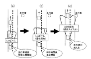
- FIGS. 6 (a) to 6 (c) when there is an oncoming vehicle, as shown in FIGS. 6 (a) to 6 (c), first, when the distance from the oncoming vehicle is relatively short, a short distance light (Low beam) is used. Irradiation is performed (FIG. 6A). And if the oncoming vehicle passes and the distance to the next oncoming vehicle is relatively far, it waits until the immediate response time or calculation time has elapsed, and then it is assumed that the long distance light is turned on and within the irradiation range. Irradiation is performed with a short-distance light while moving the irradiation range in the horizontal direction so that no other vehicle is included in the vehicle (FIG. 6B).
- a short distance light Low beam
- irradiation with the long-distance light is performed (FIG. 6C).
- the irradiation with the long distance light is terminated. That is, the irradiation is performed only with the short distance light.
- FIG. 7 (b) shows an example of irradiation with only a short-distance light in the same situation as FIG. 7 (a). In this example, it is difficult to visually recognize a pedestrian or an obstacle. I understand.
- the calculation unit 10 acquires position information of other vehicles existing around the host vehicle, and sets an irradiation range according to the position of the other vehicle. And the change output which changes the irradiation range of the light of the own vehicle so that it may become the set irradiation range is performed. Further, it is prohibited to output to change the irradiation range until a preset standby time elapses.
- the irradiation range by the light is not changed until the standby time elapses, so that the driver feels bothered by frequently changing the irradiation range. This can be suppressed.
- the calculation unit 10 also acquires the moving direction of the other vehicle, and sets the length of the standby time according to the moving direction of the other vehicle. According to such a light control device 1, it is determined whether or not the irradiation range should be changed promptly according to the moving direction of the other vehicle, and the length of the standby time can be set according to the determination result. . Therefore, it is possible to set the responsiveness when changing the irradiation range according to the situation.
- the calculation unit 10 determines whether the other vehicle is an oncoming vehicle that travels toward the own vehicle or a preceding vehicle that travels in the same direction as the own vehicle according to the moving direction of the other vehicle. judge. Then, when the other vehicle is a preceding vehicle, the standby time is set shorter than when the other vehicle is an oncoming vehicle. According to such a light control device 1, it is possible to appropriately set the standby time according to whether the other vehicle is an oncoming vehicle or a preceding vehicle.
- the calculation unit 10 has a light optical axis direction that overlaps with other vehicles within the irradiable range when the swivel mechanism that changes the light optical axis direction to the horizontal direction is driven.
- the irradiation range is repeatedly set according to the position of the other vehicle so as not to become.
- the irradiation range is set within the irradiable range when the swivel mechanism is used so that the other vehicle is less likely to dazzle following the position of the other vehicle, and becomes this irradiation range.
- the optical axis direction can be changed.
- the calculation unit 10 is configured such that the optical axis of one of the pair of lights provided in the own vehicle is located on the left outer side of the other vehicle, and the optical axis of the other light is the other vehicle.
- the irradiation range is set so as to be located on the right outer side of. According to such a light control device 1, a wider range can be set within the irradiation range.
- the calculation unit 10 sets the irradiation possible range only with the short distance light as the irradiation range when there is another vehicle within a preset reference distance. II) When there is no other vehicle within the reference distance, and when it is assumed that the long distance light is turned on, and the other vehicle is included in the irradiation range, the long distance light is turned on. When it is assumed, the irradiation range is set in the horizontal direction so that other vehicles are not included in the irradiation range, and the irradiation possible range using only the short-distance light is set as the irradiation range of the long-distance light.
- the calculation unit 10 sets the irradiation range within the irradiation range within the long-distance light, and if the other vehicle can be prevented from being included in the irradiation range, The irradiation range is set so that other vehicles are not included, and if another vehicle is included in the irradiation range, the irradiation possible range by the short distance light is set as the irradiation range.
- a light control device 1 when illuminating with a long distance light, if the other vehicle is dazzled no matter how the irradiation range is set, irradiation with the short distance light is performed. By switching, it can be made difficult to dazzle other vehicles.
- Embodiments of the present invention are not limited to the above-described embodiments, and can take various forms as long as they belong to the technical scope of the present invention.
- the camera 11 extracts a light source estimated to be a vehicle from the captured image, detects the distance, and detects the coordinates of the rightmost and leftmost light sources.
- the calculating part 10 may perform about at least one part of these processes. In this case, for example, the camera 11 may transmit the captured image to the calculation unit 10 as it is.
- the same set time (immediate response time, calculation time, stabilization time) is set for the left and right headlights 20, but different set times are set for the left and right headlights 20, respectively. May be.
- each headlight 20 is configured to include a long-distance light and a short-distance light, but may be configured to include only a long-distance light.
- the passing area 41 may be shielded by the left and right shutters 31 and 33.
- processing of S280 in the embodiment corresponds to “irradiation range change prohibiting means” in the claims
- processing of S170 to S250 in the embodiment corresponds to “waiting time setting means” in the claims.
- SYMBOLS 1 Light control apparatus, 3 ... CAN communication line, 5 ... LIN communication line, 10 ... Operation part, 11 ... Camera, 12 ... Vehicle speed sensor, 13 ... Steering angle sensor, 20 ... Headlight, 21 ... Control part, 23 ... Vertical direction control motor, 25 ... Horizontal direction control motor, 27 ... Right shutter control motor, 29 ... Left shutter control motor, 31 ... Left shutter, 33 ... Right shutter, 41 ... Passing area.
Landscapes
- Engineering & Computer Science (AREA)
- Mechanical Engineering (AREA)
- Lighting Device Outwards From Vehicle And Optical Signal (AREA)
Priority Applications (2)
| Application Number | Priority Date | Filing Date | Title |
|---|---|---|---|
| CN201380016553.XA CN104220299B (zh) | 2012-03-28 | 2013-02-04 | 灯光控制设备和灯光控制方法 |
| US14/376,949 US10279729B2 (en) | 2012-03-28 | 2013-02-04 | Light control device and light control program |
Applications Claiming Priority (2)
| Application Number | Priority Date | Filing Date | Title |
|---|---|---|---|
| JP2012074640A JP5928077B2 (ja) | 2012-03-28 | 2012-03-28 | ライト制御装置、およびライト制御プログラム |
| JP2012-074640 | 2012-03-28 |
Publications (1)
| Publication Number | Publication Date |
|---|---|
| WO2013145859A1 true WO2013145859A1 (ja) | 2013-10-03 |
Family
ID=49259144
Family Applications (1)
| Application Number | Title | Priority Date | Filing Date |
|---|---|---|---|
| PCT/JP2013/052438 Ceased WO2013145859A1 (ja) | 2012-03-28 | 2013-02-04 | ライト制御装置、およびライト制御プログラム |
Country Status (4)
| Country | Link |
|---|---|
| US (1) | US10279729B2 (https=) |
| JP (1) | JP5928077B2 (https=) |
| CN (1) | CN104220299B (https=) |
| WO (1) | WO2013145859A1 (https=) |
Families Citing this family (8)
| Publication number | Priority date | Publication date | Assignee | Title |
|---|---|---|---|---|
| WO2015005377A1 (ja) * | 2013-07-11 | 2015-01-15 | 株式会社小糸製作所 | 車両用前照灯の配光制御方法および配光制御装置 |
| CN111993992B (zh) * | 2015-04-10 | 2024-07-09 | 麦克赛尔株式会社 | 投射型显示装置 |
| JP6211569B2 (ja) * | 2015-08-27 | 2017-10-11 | 株式会社小糸製作所 | 車両灯具システム |
| US10562439B2 (en) * | 2016-01-19 | 2020-02-18 | Harman International Industries, Incorporated | Techniques for optimizing vehicle headlights based on situational awareness |
| JP6648564B2 (ja) * | 2016-03-11 | 2020-02-14 | 株式会社デンソー | 車両用光照射システム |
| DE102017000807A1 (de) * | 2017-01-28 | 2018-08-02 | GM Global Technology Operations LLC (n. d. Ges. d. Staates Delaware) | Verfahren zum Betrieb einer Scheinwerferanordnung, Scheinwerfersystem sowie Kraftfahrzeug |
| DE102018200025A1 (de) * | 2018-01-02 | 2019-07-04 | Ford Global Technologies, Llc | Fahrzeugbeleuchtung |
| WO2023032785A1 (ja) * | 2021-09-02 | 2023-03-09 | 本田技研工業株式会社 | 車両、車両の制御方法及びプログラム |
Citations (3)
| Publication number | Priority date | Publication date | Assignee | Title |
|---|---|---|---|---|
| JP2006021631A (ja) * | 2004-07-07 | 2006-01-26 | Koito Mfg Co Ltd | 車両用照明システム |
| JP2011235678A (ja) * | 2010-05-06 | 2011-11-24 | Koito Mfg Co Ltd | 車両用灯具システム、制御装置、および車両用灯具 |
| JP2012180051A (ja) * | 2011-03-02 | 2012-09-20 | Stanley Electric Co Ltd | 車両用前照灯制御装置および車両用前照灯システム |
Family Cites Families (7)
| Publication number | Priority date | Publication date | Assignee | Title |
|---|---|---|---|---|
| US4891559A (en) * | 1985-06-13 | 1990-01-02 | Nippondenso Soken, Inc. | Apparatus for controlling a headlight of a vehicle |
| US6587573B1 (en) * | 2000-03-20 | 2003-07-01 | Gentex Corporation | System for controlling exterior vehicle lights |
| JP3149823B2 (ja) * | 1997-07-24 | 2001-03-26 | トヨタ自動車株式会社 | 車両用照明装置 |
| JP4253271B2 (ja) * | 2003-08-11 | 2009-04-08 | 株式会社日立製作所 | 画像処理システム及び車両制御システム |
| JP4466701B2 (ja) * | 2007-09-10 | 2010-05-26 | 株式会社デンソー | ライト制御装置 |
| EP2602154B1 (en) | 2010-08-06 | 2016-03-30 | Toyota Jidosha Kabushiki Kaisha | Vehicle light distribution control device and method |
| JP6001238B2 (ja) * | 2011-02-14 | 2016-10-05 | 株式会社小糸製作所 | 車両用前照灯の配光制御装置 |
-
2012
- 2012-03-28 JP JP2012074640A patent/JP5928077B2/ja not_active Expired - Fee Related
-
2013
- 2013-02-04 WO PCT/JP2013/052438 patent/WO2013145859A1/ja not_active Ceased
- 2013-02-04 US US14/376,949 patent/US10279729B2/en active Active
- 2013-02-04 CN CN201380016553.XA patent/CN104220299B/zh not_active Expired - Fee Related
Patent Citations (3)
| Publication number | Priority date | Publication date | Assignee | Title |
|---|---|---|---|---|
| JP2006021631A (ja) * | 2004-07-07 | 2006-01-26 | Koito Mfg Co Ltd | 車両用照明システム |
| JP2011235678A (ja) * | 2010-05-06 | 2011-11-24 | Koito Mfg Co Ltd | 車両用灯具システム、制御装置、および車両用灯具 |
| JP2012180051A (ja) * | 2011-03-02 | 2012-09-20 | Stanley Electric Co Ltd | 車両用前照灯制御装置および車両用前照灯システム |
Also Published As
| Publication number | Publication date |
|---|---|
| CN104220299B (zh) | 2017-03-15 |
| US10279729B2 (en) | 2019-05-07 |
| CN104220299A (zh) | 2014-12-17 |
| JP2013203249A (ja) | 2013-10-07 |
| US20150246633A1 (en) | 2015-09-03 |
| JP5928077B2 (ja) | 2016-06-01 |
Similar Documents
| Publication | Publication Date | Title |
|---|---|---|
| JP5928077B2 (ja) | ライト制御装置、およびライト制御プログラム | |
| CN105922928B (zh) | 车辆用前照灯控制装置 | |
| CN101190664B (zh) | 车辆照明系统 | |
| JP6075331B2 (ja) | 車両用照明装置 | |
| US9193297B2 (en) | Vehicle light distribution control device and vehicle light distribution control method | |
| CN103249597A (zh) | 车辆配光控制装置以及方法 | |
| JP2015033944A (ja) | 車両用前照灯の点灯制御装置、車両用前照灯システム | |
| CN104411541A (zh) | 车辆用头灯配光控制装置 | |
| CN111824004B (zh) | 车辆用配光控制装置 | |
| CN104349937B (zh) | 控制车辆的车灯的照射范围的装置及其方法 | |
| JP6214290B2 (ja) | 前照灯制御装置 | |
| JP5195390B2 (ja) | 前方照射自動制御装置 | |
| JP2013252796A (ja) | 車両用前照灯の点灯制御装置、車両用前照灯システム | |
| JP2020026199A (ja) | ヘッドランプ制御方法及びヘッドランプ制御装置 | |
| JP2014101069A (ja) | 車両用前照灯の点灯制御装置、車両用前照灯システム | |
| JP2015033954A (ja) | 車両用前照灯の点灯制御装置、車両用前照灯システム | |
| JP4749020B2 (ja) | 車両用前照灯装置 | |
| JP6895264B2 (ja) | 車両用照明の表示方法及び表示制御装置 | |
| JP6725396B2 (ja) | 車両用灯具システム | |
| JP2013060108A (ja) | 前照灯制御装置 | |
| JP2019202656A (ja) | 車両用灯具の制御装置、車両用灯具の制御方法、車両用灯具システム | |
| JP6087736B2 (ja) | 前照灯制御装置 | |
| JP5636483B2 (ja) | 車両用前照灯の配光制御システム | |
| WO2018146801A1 (ja) | 車両用照明の制御方法及び車両用照明の制御装置 | |
| JP2019137324A (ja) | 車両用灯具の点灯制御装置、車両用灯具の点灯制御方法、車両用灯具システム |
Legal Events
| Date | Code | Title | Description |
|---|---|---|---|
| 121 | Ep: the epo has been informed by wipo that ep was designated in this application |
Ref document number: 13770024 Country of ref document: EP Kind code of ref document: A1 |
|
| WWE | Wipo information: entry into national phase |
Ref document number: 14376949 Country of ref document: US |
|
| NENP | Non-entry into the national phase |
Ref country code: DE |
|
| 122 | Ep: pct application non-entry in european phase |
Ref document number: 13770024 Country of ref document: EP Kind code of ref document: A1 |