WO2013145450A1 - 情報提供プログラム、情報提供装置および情報提供方法 - Google Patents
情報提供プログラム、情報提供装置および情報提供方法 Download PDFInfo
- Publication number
- WO2013145450A1 WO2013145450A1 PCT/JP2012/081625 JP2012081625W WO2013145450A1 WO 2013145450 A1 WO2013145450 A1 WO 2013145450A1 JP 2012081625 W JP2012081625 W JP 2012081625W WO 2013145450 A1 WO2013145450 A1 WO 2013145450A1
- Authority
- WO
- WIPO (PCT)
- Prior art keywords
- message
- user
- information
- display screen
- Prior art date
Links
Images


Classifications
-
- H—ELECTRICITY
- H04—ELECTRIC COMMUNICATION TECHNIQUE
- H04L—TRANSMISSION OF DIGITAL INFORMATION, e.g. TELEGRAPHIC COMMUNICATION
- H04L51/00—User-to-user messaging in packet-switching networks, transmitted according to store-and-forward or real-time protocols, e.g. e-mail
- H04L51/42—Mailbox-related aspects, e.g. synchronisation of mailboxes
Definitions
- the present invention relates to an information providing program, an information providing apparatus, and an information providing method.
- e-mail which is a general communication tool, but also various communication tools other than e-mail such as chat and SNS.
- chat and SNS various communication tools other than e-mail
- the transmission of information using the message providing system is increasing.
- a dedicated application is installed and used in the information terminal device.
- an object of the present invention is to provide an information providing program, an information providing apparatus, and an information providing method capable of efficiently transmitting information using a message providing system that is a plurality of communication tools. To do.
- an electronic mail display request is accepted, and other information is received based on the identification information of the user related to the accepted electronic mail display request.
- the message stored in the message providing system is extracted, and an e-mail addressed to the user including the contents of the extracted message is created, and the e-mail addressed to the user is stored.
- FIG. 1 is an explanatory diagram of an example of the information providing method according to the first embodiment.
- FIG. 2 is an explanatory diagram of a system configuration example of the mail system 200 according to the first embodiment.
- FIG. 3 is a block diagram of a hardware configuration example of the information providing apparatus 201 according to the first embodiment.
- FIG. 4 is a block diagram of a hardware configuration example of the client terminal 202 according to the first embodiment.
- FIG. 5 is an explanatory diagram of an example of the contents stored in the user authentication DB 220 according to the first embodiment.
- FIG. 6 is an explanatory diagram of an example of the contents stored in the chat user DB 230 according to the first embodiment.
- FIG. 7 is an explanatory diagram of an example of the contents stored in the SNS user DB 240 according to the first embodiment.
- FIG. 8 is an explanatory diagram of an example of the contents stored in the setting DB 250 according to the first embodiment.
- FIG. 9 is an explanatory diagram of an example of storage contents of the login history DB 260 according to the first embodiment.
- FIG. 10 is an explanatory diagram of an example of the contents stored in the mail DB 270 according to the first embodiment.
- FIG. 11 is an explanatory diagram of an example of the contents stored in the channel sentence DB 280 according to the first embodiment.
- FIG. 12 is an explanatory diagram of an example of storage contents of the SNS message DB 290 according to the first embodiment.
- FIG. 13 is an explanatory diagram of a screen example of the mail list display screen according to the first embodiment.
- FIG. 14 is an explanatory diagram (part 1) of a screen example of the message display screen according to the first embodiment.
- FIG. 15 is an explanatory diagram (part 2) of a screen example of the message display screen according to the first embodiment.
- FIG. 16 is an explanatory diagram (part 3) of a screen example of the message display screen according to the first embodiment.
- FIG. 17 is a block diagram of a functional configuration example of the information providing apparatus 201 according to the first embodiment.
- FIG. 18 is a flowchart illustrating an example of an information providing process (chat program) procedure of the information providing apparatus 201 according to the first embodiment.
- FIG. 19 is a flowchart illustrating an example of an information providing process (SNS program) procedure of the information providing apparatus 201 according to the first embodiment.
- FIG. 20 is a flowchart (part 1) illustrating an example of an information providing process (mail program) procedure of the information providing apparatus 201 according to the first embodiment.
- FIG. 21 is a flowchart (part 2) illustrating an example of an information providing process (mail program) procedure of the information providing apparatus 201 according to the first embodiment.
- FIG. 22 is a flowchart (part 3) illustrating an example of an information provision process (mail program) procedure of the information provision apparatus 201 according to the first embodiment.
- FIG. 23 is a flowchart of an example of a specific process procedure of the linked application data recording process according to the first embodiment.
- FIG. 24 is a flowchart of an example of a specific processing procedure of the cooperative app data acquisition process according to the first embodiment.
- FIG. 25 is a flowchart (part 1) illustrating an example of an information processing procedure of the client terminal 202 according to the first embodiment.
- FIG. 26 is a flowchart (part 2) illustrating an example of an information processing procedure of the client terminal 202 according to the first embodiment.
- FIG. 27 is an explanatory diagram of an example of the contents stored in the setting DB 255 according to the second embodiment.
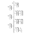
- FIG. 1 is an explanatory diagram of an example of the information providing method according to the first embodiment.
- a user normally installs a mail program 101, a chat program 102, and an SNS (Social Networking Service) program 103 on a client terminal (for example, office PC) 100 to be used, and performs mail, chat, and SNS.
- client terminal for example, office PC
- chat is a communication tool in which a plurality of users transmit information by writing messages on a set channel.
- the SNS is a service for exchanging information in a limited network. By using the SNS, a community between users can be expanded.
- the mail program 151 is installed in a client terminal (for example, a mobile notebook PC) 150 different from the client terminal 100 that is normally used.
- the client terminal 150 can send and receive mail, but cannot send and receive chat channel text and SNS messages.
- the contents of the chat channel sentence and the SNS message, which are related to the user are the same as normal mail as mail.
- the mail DB 270 to be described later it can be displayed using the mail program 151 in the same way as a normal mail. Therefore, in the client terminal 150 as well as the client terminal 100, the chat channel text and SNS message are displayed. The contents can be confirmed.
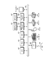
- FIG. 2 is an explanatory diagram of a system configuration example of the mail system 200 according to the first embodiment.
- the mail system 200 includes an information providing apparatus 201 and a plurality of client terminals 202 (three in the drawing).
- the information providing apparatus 201 and the plurality of client terminals 202 are connected to each other via a wired or wireless network 210 so that they can communicate with each other.
- the network 210 is, for example, the Internet, a LAN (Local Area Network), a WAN (Wide Area Network), or the like.
- the information providing apparatus 201 includes a user authentication DB (database) 220, a chat user DB 230, an SNS user DB 240, a setting DB 250, a login history DB 260, a mail DB 270, a channel sentence DB 280, and an SNS message DB 290. It is a computer that transmits and receives mail in the system 200.
- the information providing apparatus 201 is, for example, a mail server.
- the user authentication DB 220, chat user DB 230, SNS user DB 240, setting DB 250, login history DB 260, mail DB 270, channel sentence DB 280 and SNS message DB 290 will be described later with reference to FIGS.
- the client terminal 202 is a computer that displays, creates, and transmits and receives mail.
- the client terminal 202 is, for example, a PC (personal computer), a notebook PC, a mobile phone, a PDA (Personal Digital Assistant), a smartphone, a tablet terminal, or the like used by a user of the mail system 200.
- the mail is, for example, a web mail displayed, created, and transmitted / received by the browser of the client terminal 202.
- FIG. 3 is a block diagram of a hardware configuration example of the information providing apparatus 201 according to the first embodiment.
- an information providing apparatus 201 includes a CPU (Central Processing Unit) 301, a ROM (Read-Only Memory) 302, a RAM (Random Access Memory) 303, an I / F (Interface) 304, and a magnetic disk drive. 305, a magnetic disk 306, an optical disk drive 307, an optical disk 308, and an input device 309. Each component is connected by a bus 300.
- CPU Central Processing Unit
- ROM Read-Only Memory
- RAM Random Access Memory
- I / F Interface
- the CPU 301 governs overall control of the information providing apparatus 201.
- the ROM 302 stores a program such as a boot program.
- the RAM 303 is used as a work area for the CPU 301.
- the I / F 304 is connected to the network 210 through a communication line, and is connected to other devices such as the client terminal 202 via the network 210.
- the I / F 304 controls an internal interface with the network 210 and controls input / output of data from other devices.
- a modem or a LAN adapter may be employed as the I / F 304.
- the magnetic disk drive 305 controls the reading / writing of the data with respect to the magnetic disk 306 according to control of CPU301.
- the magnetic disk 306 stores data written under the control of the magnetic disk drive 305.
- the optical disk drive 307 controls reading / writing of data with respect to the optical disk 308 according to the control of the CPU 301.
- the optical disk 308 stores data written under the control of the optical disk drive 307, and causes the computer to read data stored on the optical disk 308.
- the input device 309 inputs data such as letters, numbers, and various instructions.
- the input device 309 is, for example, a keyboard having keys for input or a touch panel type input pad.
- the information providing apparatus 201 may include a display for displaying data in addition to the above-described components.
- the information providing apparatus 201 may not include the optical disk drive 307 and the optical disk 308 among the above-described components, for example.
- FIG. 4 is a block diagram of a hardware configuration example of the client terminal 202 according to the first embodiment.
- the client terminal 202 includes a CPU 401, a ROM 402, a RAM 403, a magnetic disk drive 404, a magnetic disk 405, an optical disk drive 406, an optical disk 407, a display 408, an I / F 409, a keyboard 410, and the like.
- the CPU 401 governs overall control of the client terminal 202.
- the ROM 402 stores programs such as a boot program.
- the RAM 403 is used as a work area for the CPU 401.
- the magnetic disk drive 404 controls the reading / writing of the data with respect to the magnetic disk 405 according to control of CPU401.
- the magnetic disk 405 stores data written under the control of the magnetic disk drive 404.
- the optical disc drive 406 controls reading / writing of data with respect to the optical disc 407 according to the control of the CPU 401.
- the optical disk 407 stores data written under the control of the optical disk drive 406, or causes the computer to read data stored on the optical disk 407.
- the display 408 displays data such as a document, an image, and function information as well as a cursor, an icon, or a tool box.
- a CRT for example, a CRT, a TFT liquid crystal display, a plasma display, an organic EL display, or the like can be adopted.
- the I / F 409 is connected to the network 210 via a communication line, and is connected to another device such as the information providing device 201 via the network 210.
- the I / F 409 controls an internal interface with the network 210 and controls input / output of data from other devices.
- a modem or a LAN adapter may be employed as the I / F 409.
- the keyboard 410 has keys for inputting characters, numbers, various instructions, etc., and inputs data. Moreover, a touch panel type input pad or a numeric keypad may be used.
- the mouse 411 moves the cursor, selects a range, moves the window, changes the size, and the like.
- a touch panel, a trackball, a joystick, or the like may be used as long as it has the same function as a pointing device.
- the scanner 412 optically reads an image and takes in the image data into the client terminal 202.
- the scanner 412 may have an OCR (Optical Character Reader) function.
- the printer 413 prints image data and document data.
- a laser printer or an ink jet printer can be adopted.
- the client terminal 202 may not include the optical disk drive 406, the optical disk 407, the scanner 412, the printer 413, and the like among the above-described components.
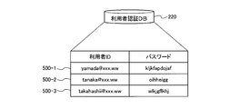
- FIG. 5 is an explanatory diagram of an example of the contents stored in the user authentication DB 220 according to the first embodiment.
- the user authentication DB 220 has at least fields of “user ID” and “password”. By setting information in each field, authentication information of each user (for example, authentication information 500- 1 to 500-3) are stored as records.
- the user ID is an identifier of the user of the mail system 200.
- the password is a code for authenticating the user of the mail system 200.
- the authentication information 500-1 indicates the password “kljkfadojaf” of the user with the user ID “yamada@xxx.ww”.
- the user ID “yamada@xxx.ww” is also used as “message ID” and “destination” of the mail DB 270 described later.
- FIG. 6 is an explanatory diagram of an example of the contents stored in the chat user DB 230 according to the first embodiment.
- the chat user DB 230 has at least fields of “user ID”, “chat ID”, “automatic JOIN channel”, and “current JOIN channel”, and by setting information in each field,
- Each chat user information (for example, chat user information 600-1 to 600-5) is stored.
- the user ID is an identifier of the user of the mail system 200, like the user authentication DB 220 shown in FIG.
- the chat ID is an identifier of the user in the chat, and corresponds to the user ID on a one-to-one basis.
- the automatic JOIN channel is a channel registered in advance corresponding to the user ID in order to automatically obtain a message (speech) from the channel sentence DB 280 in the linked application data recording process described later.
- the current JOIN channel is information regarding the channel in which the user associated with the user ID is currently participating. Therefore, the user registers a channel for which a message is automatically acquired as a mail from among the current JOIN channels as an automatic JOIN channel.
- the chat ID of the user with the user ID “yamada@xxx.www” is “yamada”
- the automatic JOIN channel is “health management”
- the current JOIN channel is “Health Management, 2010”. All or part of the automatic JOIN channel and the current JOIN channel can be added, changed, or deleted by a predetermined operation of each user.
- FIG. 7 is an explanatory diagram of an example of the contents stored in the SNS user DB 240 according to the first embodiment.
- the SNS user DB 240 has at least fields of “user ID”, “nickname”, “icon”, and “registered community”, and by setting information in each field, each SNS user information (For example, SNS user information 700-1 to 700-5) is stored.
- the user ID is an identifier of the user of the mail system 200, like the user authentication DB 220 shown in FIG. 5 and the chat user DB 230 shown in FIG.
- the nickname is user identification information in the SNS, and corresponds to the user ID on a one-to-one basis.
- the icon is an image (illustration, photograph, etc.) added to the user's message, and makes it easy to visually distinguish between the user's message and other users' messages.
- the registered community corresponds to the user ID in advance in order to automatically obtain a message (speech) from the SNS message DB 290 in the linked application data recording process described later. It is a registered channel.
- the nickname of the user with the user ID “yamada@xxx.www” is “Yamada”
- the icon is a male illustration image
- the registered community is “education community”. It shows that there is. All or part of the registered community can be added, changed, or deleted by a predetermined operation of each user.
- FIG. 8 is an explanatory diagram of an example of the contents stored in the setting DB 250 according to the first embodiment.
- the setting DB 250 has at least fields of “application (application) name”, “channel name / community name”, and “setting time”. By setting information in each field, the setting DB 250 sets each field.
- Setting information (for example, setting information 800-1 to 800-7) is stored.
- the setting information 800-1 to 800-4 is a setting relating to the chat channel
- the setting information 800-5 to 800-7 is a setting relating to the SNS community.
- the set time is a time for determining whether or not acquisition is possible when a message (speech) is automatically acquired from the channel sentence DB 280 or the SNS message DB 290 in the cooperative application data acquisition process described later. Therefore, the CPU 301 acquires from the channel sentence DB 280 or the SNS message DB 290 when the time since the previous acquisition has passed this set time, and does not acquire it when the set time has not passed.
- the setting time can be set not only in minutes and hours but also in days and weeks.
- the setting time can be set for each user even in the same channel and community, and can be changed by a predetermined operation of the user or the administrator. Therefore, by setting the setting time short in each channel and community, the user can check messages frequently. In addition, by setting the set time longer, it is possible to eliminate the troublesomeness that the user frequently displays as mail on the mail list display screen in the same manner as other mails.
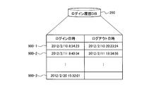
- FIG. 9 is an explanatory diagram of an example of storage contents of the login history DB 260 according to the first embodiment.
- the login history DB 260 has fields of “login date” and “logout date”, and stores log history information for each user's mail system 200 by setting date information in each field. ing.
- this login history DB 260 is shown as being provided for each user. Further, in FIG. 9, a “user ID” field (not shown) may be further provided so that it can be managed for each user.
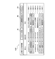
- FIG. 10 is an explanatory diagram of an example of the contents stored in the mail DB 270 according to the first embodiment.
- the mail DB 270 includes at least “transmission / reception information”, “message ID”, “sender ID”, “sending date / time”, “destination”, “subject”, “cooperation application (application) name”, “channel name”. / Community name "," text ", and” cooperation ID "fields.
- mail information for example, mail information 1000-1 to 1000-7) is stored.
- the mail information 1000-1, 1000-4, 1000-5 is normal mail
- the mail information 1000-2, 1000-3, 1000-6, 1000-7 is It is a linked app.
- the mail DB 270 is shown to be provided for each user. However, for a plurality of users, fields such as “sender ID” and “destination” in a common database, or illustrations are shown. In addition to omission, it may be possible to distinguish and manage for each user from the provided fields. Therefore, FIG. 10 shows “yamada @ xxx.” Which is the user ID from the “sender ID” and “destination” fields. Only information corresponding to “ww” may be collected from the mail DB 270.
- the transmission / reception information is information for distinguishing between received mail (“receive”) and transmitted mail (“transmit”).
- the message ID is an identifier for uniquely identifying mail transmitted / received by the mail system 200.
- the character string should be unique as a whole, but in general, the right side of the @ mark is the domain name, the left side is the date and time, user ID, etc. As a whole, the string is unique. In this embodiment, the character string is such that the mail can be easily identified.
- mail information 1000-2, 1000-3, 1000-5, 1000-6, 1000-7 is a received mail
- mail information 1000-1, 1000-4 is a transmitted mail.
- the sender ID is an identifier of the sender of the mail, for example, the user ID of the user who is the sender.
- the outgoing date / time is the outgoing date / time of the mail.
- the destination is a mail destination, for example, a mail address of a user who is a mail transmission destination.
- the destination includes, for example, CC (Carbon Copy) and BCC (Blind Carbon Copy).
- the subject is the subject of the email.
- the subject is displayed as a part of the summary information of the mail on a list display screen 1300 shown in FIG.
- the linked application (application) name is information related to another message providing system to be linked.
- “Chat” is a chat providing system (chat application), which indicates that the chat user DB 230 and the channel sentence DB 280 are referred to
- “SNS” is an SNS providing system (SNS application), This indicates that the SNS user DB 240 and the SNS message DB 290 are referred to.
- the mail information 1000-3, 1000-6, 1000-7 of the cooperative application is chat.
- the mail information 1000-2 of the cooperative application is SNS.
- the channel name / community name is a channel name stored in the automatic JOIN channel in the chat user DB 230 or a community name stored in the registered community in the SNS user DB 240.
- the text is a message described as the text information of the mail.
- standard text for example, “Chat: Linked from XX Community. Hh: mm-HH: MM up to MM.”, “SNS: Linked from XX Community. Hh: mm After -HH: MM up to MM ')
- the message content extracted from the channel sentence DB 280 or the SNS message DB 290 becomes the text information.
- the cooperation ID matches the cooperation ID extracted from the channel sentence DB 280 and the SNS message DB 290 described later. The contents of the cooperation ID will be described later.
- the “cooperation application name”, “channel name / community name”, and “cooperation ID” are stored only in the mail associated with the application, and the “cooperation application name” is included in the normal mail that is not the cooperation application. , “Channel name / community name” and “cooperation ID” are not stored.
- the mail information 1000-1 has a user ID “yamada @ xxx. ww ”user's transmitted mail.
- the “transmission / reception information” of the mail is “transmission”, and the “message ID” is “system2 @ xxx. www “and” sender ID “are” yamada @ xxx. “ww”, “date of transmission” is “2011/2/20 16:39:29”, and “destination” is “tanaka @ xxx. “ww”, “subject” is “XX system failure”, and “text” is “Yamada”. ... ". Since this mail information 1000-1 is a normal mail, no information is entered in the fields of “cooperative application name”, “channel name / community name”, and “cooperation ID”.
- the mail information 1000-2 has a user ID “yamada @ xxx.
- the information regarding the received mail of the user “ww”.
- the “transmission / reception information” of the mail is “reception”, and the “message ID” is “apprenkei3 @ xxx.
- “ww”, “sender ID” is “application linkage”, “sending date / time” is “2011/2/20 16:32:32”, and “destination” is “yamada @ xxx.
- WW “Subject” is “SNS: Education Community”, “Linked App Name” is “SNS”, “Channel Name / Community Name” is “educationion”, and “Text” is “SNS: Cooperation from Education Community”. .., ”“ Linkage ID ”is“ SNS00001 ”.
- the mail information 1000-3 also has a user ID “yamada @ xxx.
- the information regarding the received mail of the user “ww”.
- the “transmission / reception information” of the mail is “reception”, and the “message ID” is “apprenkei2 @ xxx.
- “ww”, “sender ID” is “application linkage”, “sending date / time” is “2011/2/20 16:32:07”, and “destination” is “yamada @ xxx.
- “ww” “Subject” is “Chat: Health Management Channel”, “Linked App Name” is “Chat”, “Channel Name / Community Name” is “Health Management”, “Text” is “Chat: Health Management Channel” Cooperation. .., ”“ Cooperation ID ”is“ CH00002 ”.
- FIG. 11 is an explanatory diagram of an example of the contents stored in the channel sentence DB 280 according to the first embodiment.
- a channel sentence DB 280 is a database for storing channel sentence information in chat, and has at least fields of “channel name”, “transmission date / time”, “chat ID”, “message content”, and “cooperation ID”.
- channel sentence information (for example, channel sentence information 1100-1 to 1100-13) is stored as a record.
- the channel sentence information may be managed for each channel name as shown in FIG.
- the sending date / time is the sending date / time of the message.
- the chat ID is a user identifier in the chat.
- the information in the chat ID field corresponds to the information in the chat ID field in the chat user DB 230. Thereby, the user ID of the channel sentence information can be specified.
- the content of the remark is the content of the message remarked by the user.
- the cooperation ID is an identifier given when channel sentence information is extracted as application cooperation.
- the same link ID is assigned to each of the plurality of pieces of channel sentence information extracted at the same time and stored. Whether the channel sentence has already been extracted or not extracted can be determined based on whether or not this linkage ID is assigned. Further, it is possible to determine at which timing the channel sentence is extracted based on the difference in the cooperation ID.
- the cooperation ID is stored in the field of the mail DB 270 “cooperation ID” as application cooperation mail information.
- FIG. 12 is an explanatory diagram of an example of storage contents of the SNS message DB 290 according to the first embodiment.
- the SNS message DB 290 is a database for storing SNS message information in the SNS, and has at least fields of “community name”, “sending date / time”, “SNS nickname”, “speech content”, and “cooperation ID”.
- SNS message information (for example, message information 1200-1 to 1200-3) is stored as a record.
- the SNS message information may be managed for each community name as shown in FIG.
- the sending date / time is the sending date / time of the message.
- the SNS nickname is user identification information in the SNS.
- the information in the SNS nickname field corresponds to the information in the nickname field of the SNS user DB 240. Thereby, the user ID of the SNS message information can be specified.
- the content of the remark is the content of the message remarked by the user.
- the cooperation ID is an identifier given when SNS message information is extracted as application cooperation.
- the same linkage ID is assigned to each of the plurality of SNS message information extracted at the same time and stored. It can be determined whether the SNS message has already been extracted or not yet extracted depending on whether or not this linkage ID is assigned. Further, it is possible to determine at what timing the SNS message is extracted based on the difference in the linkage ID.
- the cooperation ID is stored in the “cooperation ID” field of the mail DB 270 as application cooperation mail information.
- Email list display screen example Next, a mail list display screen displayed on the display 408 of the client terminal 202 shown in FIG. 4 will be described.
- the screen information of the mail list display screen is created by, for example, the information providing apparatus 201 and transmitted to the client terminal 202.
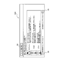
- FIG. 13 is an explanatory diagram of a screen example of the mail list display screen according to the first embodiment.
- a mail list display screen 1300 shown in FIG. 13 is displayed on the display 408.
- the mail transmitted to the user with the user ID “yamada@xxx.ww” and the mail transmitted by the user with the user ID “yamada@xxx.ww” are displayed.
- Summary information (for example, summary information 1300-1 to 1300-7) is displayed.
- the mail list display screen 1300 includes a “message creation” button B1, an “application link latest reception” button B2, and a “logout” button B3.
- a message creation screen display request (not shown) is displayed on the display 408 as a result of sending a message creation screen display request for creating a new mail to the information providing apparatus 201.
- the “application cooperation latest reception” button B2 corresponds to step S2101 of the flowchart of FIG. 21 described later.
- the cooperation application recording of step S2008 of the flowchart of FIG. The process (refer to the flowchart of FIG. 23 described later) is executed, and an updated mail list display screen 1300 including the latest information of application cooperation is displayed on the display 408.
- the “logout” button B3 is clicked, the log list request is transmitted to the information providing apparatus 201, and as a result, the display of the mail list display screen 1300 is terminated.
- the mail list display screen 1300 shows an outline of the mail sent to the user having the user ID “yamada@xxx.ww” and the mail having the user ID “yamada@xxx.ww” as the sender.
- Information for example, summary information 1300-1 to 1300-7) is displayed.
- the summary information is information indicating the sender of the mail, the transmission date and time, and the subject.
- the mail sender ID is shown as the mail sender.
- the title of the email is shown as the subject of the email.
- the summary information 1300-1 indicates the mail sender “yamada@xxx.www”, the transmission date and time “2011/2/20 16:39:29” and the subject “XX system failure”.
- the summary information 1300-2 indicates the mail sender “application linkage”, the transmission date and time “2011/2/20 16:32:32”, and the subject “SNS: education community”. Further, for example, the summary information 1300-3 indicates the mail sender “application linkage”, the transmission date and time “2011/2/20 16:32:07”, and the subject “chat: health management channel”.
- each summary information is displayed for each normal mail, chat application cooperation, and SNS application cooperation, for example, by changing the character color or font, changing the background color, etc. May be easily distinguished.
- sorting may be performed for each of normal mail, chat application cooperation, and SNS application cooperation.
- any outline information is displayed by moving a cursor (not shown) displayed on the mail list display screen 1300 by a user operation input using the keyboard 410 or the mouse 411 shown in FIG. 4.
- the mail corresponding to the summary information is selected.
- the SNS message display screen 1400 shown in FIG. 13 when the user requests to display the summary information 1300-2, the SNS message display screen 1400 shown in FIG.
- a “return to mail list” button B4 corresponds to step S2204 in the flowchart of FIG.
- the cooperative application data acquisition process in step S2107 is executed, and the updated mail list display screen 1300 is displayed on the display 408. .
- the “previous educational community message” arrow button B5 and the “next educational community message” arrow button B6 correspond to step S2203 of the flowchart of FIG.
- the previous / next cooperation ID is acquired from the mail DB 270 in step S2205, and a message display screen 1400 (not shown) including a message to which the acquired cooperation ID is assigned is displayed. 408.
- a “return to mail list” button B7 has the same function as the “return to mail list” button B4 shown in FIG.
- an arrow button B6 for "Next Education Community Message” Has the same function.
- the “return to mail list” button B7, the “previous health management channel message” arrow button B8, and the “next health management channel message” arrow button B9 are displayed on the message display screen in FIG. It has the same function as 1500.
- the message display screens 1400 to 1600 in FIGS. 14 to 16 are not provided with the “logout” button B3 provided in the mail list display screen 1300 shown in FIG. In 1600, a “logout” button similar to the “logout” button B3 may be provided. By doing so, it is possible to log out directly from the message display screens 1400 to 1600 without returning to the mail list display screen 1300.
- FIG. 17 is a block diagram of a functional configuration example of the information providing apparatus 201 according to the first embodiment.
- the information providing apparatus 201 includes a reception unit 1701, a message extraction unit 1702, a mail creation unit 1703, a mail storage unit 1704, a list display screen creation unit 1705, an output unit 1706, and a mail extraction unit 1707. And including.
- the receiving unit 1701 to the mail extracting unit 1707 are functions as control units. Specifically, for example, programs stored in storage devices such as the ROM 302, the RAM 303, the magnetic disk 306, and the optical disk 308 shown in FIG. The function is realized by causing the CPU 301 to execute it or by using the I / F 304.
- the accepting unit 1701 has a function of accepting a display request for a mail transmitted to a predetermined address or a mail transmitted from a predetermined address.
- the predetermined address is a character string for identifying the user when the mail system 200 transmits / receives mail, and is, for example, the mail address of the user.
- a plurality of predetermined addresses may exist for one user.
- the mail display request includes, for example, the user ID of the user who is the request source and the message ID of the mail that is the target of the display request.
- User ID is a user's e-mail address, for example.
- the reception unit 1701 receives a display request for the target mail from the client terminal 202, thereby receiving the display request for the mail.
- the receiving unit 1701 may receive a display request for the mail by, for example, a user operation input using the input device 309 illustrated in FIG.
- the reception unit 1701 may perform user authentication processing. Specifically, for example, when the user ID and password input screen information not shown are transmitted to the client terminal 202 and the user ID and password are received, the user authentication DB 220 shown in FIG. By referring to the user ID and the password, it is determined whether or not the user ID and the password match, thereby executing the user authentication process. If the user is authenticated, the reception unit 1701 stores the login date and time in the login history DB 260 illustrated in FIG.
- the message extraction unit 1702 extracts a message stored in another message providing system based on the identification information of the user corresponding to the address related to the mail display request received by the reception unit 1701. Specifically, for example, based on the identification information of the user, the message extraction unit 1702 extracts only messages in the group in which the user is participating from among messages stored in other message providing systems. To do.
- the message extraction unit 1702 extracts the automatic JOIN channel corresponding to the user ID from the chat user DB 230 shown in FIG. If the user ID is “yamada@xxx.ww”, the automatic JOIN channel “health management” is extracted. Then, the message extraction unit 1702 extracts channel sentence information of the channel name “health management” corresponding to the extracted “health management” from the channel sentence DB 280.
- the message extraction unit 1702 may extract only the message stored in the channel sentence DB 280 after the previous extraction. Specifically, the message extraction unit 1702, for example, a channel for which a link ID is not set from the channel sentence information of the channel name “health management” corresponding to the extracted “health management” in the channel sentence DB 280. Only sentence information may be extracted.
- the message extraction unit 1702 extracts a message stored in another message providing system when the time from the previous extraction to the current display request has passed a preset set time. You may do it. Specifically, for example, the message extraction unit 1702 acquires a set time from the setting DB 250 shown in FIG. 8, and compares the set time with the time from the previous extraction until the current display request. The message may be extracted only when the time from the previous extraction to the current display request exceeds the set time.
- the message extraction unit 1702 performs the mail extraction process only when one hour has passed since the previous extraction. You may make it perform.
- the message extraction unit 1702 extracts a registered community corresponding to the user ID from the SNS user DB 240 shown in FIG.
- the user ID is “yamada@xxx.ww”
- the registered community “education community” is extracted.
- the message extraction unit 1702 extracts the SNS message information of the community name “education community” corresponding to the extracted “education community” from the SNS message DB 290.
- the message extraction unit 1702 may extract only the message stored in the SNS message DB 290 after the previous extraction.
- the message extraction unit 1702 has, for example, the SNS in which the cooperation ID is not set from the SNS message information of the community name “education community” corresponding to the extracted “education community” in the SNS message DB 290. Only message information may be extracted.
- the message extraction unit 1702 extracts a message stored in another message providing system when the time from the previous extraction to the current display request has passed a preset set time. You may do it. Specifically, for example, the message extraction unit 1702 acquires a set time from the setting DB 250 shown in FIG. 8, and compares the set time with the time from the previous extraction until the current display request. The message may be extracted only when the time from the previous extraction to the current display request exceeds the set time.
- the message extraction unit 1702 performs the mail extraction process only when one hour has passed since the previous extraction. You may make it perform.
- the e-mail creation unit 1703 creates e-mail (cooperative application data) destined for the user including the content of the extracted message. Specifically, the mail creation unit 1703 newly creates a message ID, stores the created message ID in the mail DB 270, sets (stores) the user's destination as the destination, and sets the subject as the subject. An affiliate document is set (stored), the cooperative application name is stored, the channel name / community name is stored, the content of the message extracted in the text is registered (stored), and the cooperative ID is stored. By doing so, the cooperative application data is stored in the mail DB 270 in the same manner as normal mail.
- the e-mail storage unit 1704 stores e-mails with the user as the sender or destination.
- the mail storage unit 1704 can realize its function by, for example, the mail DB 270 shown in FIG.
- the list display screen creation unit 1705 creates a list display screen for the user's email that includes summary information of the email based on the content of the email stored in the email storage unit 1704. Specifically, for example, a screen for extracting a caller ID, a transmission date / time, and a subject from the mail DB 270 and displaying a list of mail information in a predetermined format (specifically, for example, a mail list display screen shown in FIG. 13, for example) 1300).
- the output unit 1706 outputs the list display screen created by the list display screen creation unit 1705. Specifically, information on the list display screen is transmitted to the client terminal 202, and the list display screen is displayed on the display 408 of the client terminal 202 shown in FIG.
- the accepting unit 1701 accepts a mail selection request for summary information displayed in a list on the list display screen output by the output unit 1706. Specifically, on the mail list display screen 1300, a cursor (not shown) displayed on the mail list display screen 1300 is moved by a user operation input using the keyboard 410 or the mouse 411 shown in FIG. When the summary information is clicked, a mail corresponding to the summary information is selected, and by receiving the information from the client terminal 202, a mail selection request is accepted.
- the mail extraction unit 1707 extracts the content of the mail related to the accepted selection request from the mail storage unit 1704. Specifically, for example, the mail information of the message ID related to the accepted selection request is extracted from the mail DB 270. Further, the output unit 1706 outputs the contents of the extracted mail. Specifically, information on a message display screen (specifically, for example, the message display screen 1400 shown in FIG. 14 or the message display screen 1500 shown in FIG. 15) is transmitted to the client terminal 202, and the client terminal 202 The list display screen is displayed on the display 408.
- a message display screen specifically, for example, the message display screen 1400 shown in FIG. 14 or the message display screen 1500 shown in FIG. 15
- FIG. 18 is a flowchart illustrating an example of an information providing process (chat program) procedure of the information providing apparatus 201 according to the first embodiment.
- the CPU 301 acquires chat IDs of other participants participating in the automatic JOIN channel name from the chat user DB 230 shown in FIG. 6 (step S1801). Then, the CPU 301 creates a chat screen including participants in the automatic JOIN channel and transmits it to the client terminal 202 (step S1802).
- the CPU 301 determines whether a new channel name and a channel creation request have been received from the client terminal 202 (step S1803). If the CPU 301 has not received a new channel name and a channel creation request (step S1803: No), the process proceeds to step S1808. On the other hand, when the CPU 301 receives a new channel name and a channel creation request from the client terminal 202 (step S1803: Yes), a column corresponding to the new channel name is added to the channel sentence DB 280 shown in FIG. S1804).
- the CPU 301 stores the new channel name in the current JOIN channel of the user ID in the chat user DB 230 (step S1805), and adds the newly created channel to the chat screen (step S1806). Thereafter, the CPU 301 transmits the chat screen (not shown) to the client terminal 202 (step S1807).
- the CPU 301 determines whether a request for participation in the channel has been received from the client terminal 202 (step S1808).
- the request for participation in the channel has not been received (step S1808: No)
- the process proceeds to step S1812.
- the CPU 301 receives a request to join a channel (step S1808: Yes)
- the CPU 301 stores the channel name in the current JOIN channel of the user ID in the chat user DB 230 (step S1809).
- the channel is added to the chat screen (step S1810).
- the CPU 301 transmits the chat screen (not shown) to the client terminal 202 (step S1811).
- the CPU 301 determines whether a message addressed to a certain channel has been received from the client terminal 202 (step S1812).
- a message is not received (step S1812: No)
- it transfers to step S1817.
- the CPU 301 receives a message addressed to the channel (step S1812: Yes)
- the speaker and the message are stored in the channel sentence DB 280 corresponding to the channel (step S1813).
- the CPU 301 detects a chat ID having the channel as the current JOIN channel from the chat user DB 230 (step S1814). Next, the CPU 301 adds a message to the channel field of the chat screen corresponding to the detected chat ID (step S1815). Thereafter, the CPU 301 transmits the chat screen (not shown) to the client terminal 202 (step S1816).
- step S1817 determines whether an end request has been received from the client terminal 202 (step S1817). If no termination request has been received (step S1817: NO), the process proceeds to step S1803. On the other hand, when the termination request is received (step S1817: Yes), the series of processes in this flowchart is terminated.
- FIG. 19 is a flowchart of an example of an information providing process (SNS program) procedure of the information providing apparatus 201 according to the first embodiment.
- the CPU 301 acquires a registered community of the user from the SNS user DB 240 shown in FIG. 7 (step S1901). Then, the CPU 301 acquires a message corresponding to the acquired community in the SNS message DB 290 shown in FIG. 12 to create a community screen, and transmits the created community screen (not shown) to the client terminal 202 ( Step S1902).
- the CPU 301 determines whether or not a community participation request has been received from the client terminal 202 (step S1903). If no community participation request has been received (step S1903: NO), the process proceeds to step S1906. On the other hand, when the CPU 301 receives a community participation request (step S1903: Yes), the specified community name is stored in the registered community of the user's SNS user DB 240 (step S1904), and the SNS message DB 290 is stored. The message corresponding to the community is acquired to create a community screen, and the created community screen (not shown) is transmitted to the client terminal 202 (step S1905).
- the CPU 301 determines whether a message addressed to a certain community has been received from the client terminal 202 (step S1906).
- a message is not received (step S1906: No)
- it transfers to step S1908.
- the CPU 301 receives a message addressed to the community (step S1906: Yes)
- the speaker and the message are stored in the field corresponding to the community in the SNS message DB 290 (step S1907).
- step S1908 determines whether an end request has been received from the client terminal 202 (step S1908). If no termination request has been received (step S1908: NO), the process proceeds to step S1903. On the other hand, when the termination request is received (step S1908: Yes), the series of processes in this flowchart is terminated.
- 20 to 22 are flowcharts showing an example of an information providing process procedure of the information providing apparatus 201 according to the first embodiment.
- the CPU 301 determines whether a mail display request has been received from the client terminal 202 (step S2001).
- the CPU 301 waits to receive a mail display request (step S2001: No).
- the screen information of the user ID and password input screen (not shown) is transmitted to the client terminal 202 (step S2002).
- the CPU 301 determines whether a user ID and password are received from the client terminal 202 (step S2003).
- step S2003 it waits for the CPU 301 to receive the user ID and password (step S2003: No).
- step S2003: Yes the user authentication processing is executed with reference to the user authentication DB 220 shown in FIG. 5 (step S2004).
- the CPU 301 refers to the user authentication DB 220 and specifies the password corresponding to the received user ID. The CPU 301 determines whether the received password matches the specified password. As a result, when the passwords match, the CPU 301 authenticates the user. On the other hand, if the passwords do not match, the CPU 301 does not authenticate the user.
- step S2005 determines whether or not the user has been authenticated. If the user is not authenticated (step S2005: No), the CPU 301 transmits screen information of an authentication error screen (not shown) to the client terminal 202 (step S2006), and a series of processes according to this flowchart. Exit.
- step S2005 when the user is authenticated in step S2005 (step S2005: Yes), the CPU 301 records the authenticated time in the login field of the login history DB 260 shown in FIG. 9 (step S2007). Then, the linked application data recording process is executed by the CPU 301 (step S2008). The contents of the linked application data recording process in step S2008 will be described later with reference to FIG.
- the mail list display screen 1300 shown in FIG. 13 is created based on the received mail ID 270 of the user ID shown in FIG. 10 (step S2009). Specifically, e-mail information in which information in at least one of the “sender ID” and “destination” fields matches the information of the user ID is extracted, and the e-mail list display screen is based on the extracted e-mail information. Create screen information.
- the CPU 301 may create screen information of a mail list display screen in which mail generation dates and times are sorted in ascending order.
- the CPU 301 transmits the screen information of the mail list display screen to the client terminal 202 (step S2010).
- This client terminal 202 is the client terminal 202 that has requested the display request for the mail list display screen received in step S2001.
- step S2011 determines whether a display end request is received from the client terminal 202 (step S2011).
- the display end request can be made, for example, when the user presses the “logout” button B3 on the mail list screen 1300 shown in FIG. If no termination request has been received (step S2011: No), the process proceeds to step S2101 in the flowchart of FIG.
- step S2011: Yes the termination request is received (step S2011: Yes)
- the CPU 301 records the time when the termination request is received in the logout column of the login history DB 260 shown in FIG. 9 (step S2012), and ends the series of processes. To do.
- the CPU 301 determines whether or not the application cooperation latest reception request has been received from the client terminal 202 (step S2101).
- the application cooperation latest reception request can be made, for example, when the user presses the “application cooperation latest reception” button B2 on the mail list display screen 1300 shown in FIG.
- step S2101: Yes when the application cooperation latest reception request is received (step S2101: Yes), the process proceeds to step S2008 in the flowchart of FIG. 20, and the processes after step S2008 are repeatedly executed.
- step S2101 If the application cooperation latest reception request is not received in step S2101 (step S2101: No), the CPU 301 displays a list on the mail selection information, that is, the mail list display screen 1300 shown in FIG. It is determined whether a request to display a predetermined message in the summary information has been received from the client terminal 202 (step S2102). If the mail selection information is not received by the CPU 301 (step S2102: No), the process proceeds to step S2106.
- step S2103 it is determined whether or not the selected mail is an application linkage mail (step S2103). Whether or not the selected mail is an application cooperation mail is determined based on whether or not “SNS” or “chat” information is stored in the “cooperation application name” field of the mail DB 270 shown in FIG. If “SNS” or “chat” information is stored in the “linked application name” field of the mail DB 270, it is determined that the mail is an application linked mail. If neither information is recorded, the mail is not an application linked mail. (That is, it is a normal mail).
- step S2103 when the selected mail is an application cooperation mail (step S2103: Yes), the process proceeds to step S2201 in the flowchart of FIG.
- step S2103: No when the selected mail is not an application linkage mail (step S2103: No), the CPU 301 obtains the text of the selected mail, the transmission date and time from the mail DB 270 (step S2104). Then, the CPU 301 creates a message display screen (not shown) including the text, the transmission date and time, and transmits the screen information of the created message display screen to the client terminal 202 (step S2105).
- step S2106: No waits for the display request for the list display screen to be received from the client terminal 202
- step S2106: Yes when the CPU 301 receives the display request for the list display screen
- step S2107 A cooperative application data acquisition process is executed (step S2107).
- the contents of the cooperative application data acquisition process in step S2106 will be described later with reference to FIG.
- step S2107 it transfers to step S2009 of the flowchart of FIG. 20, and performs the process after step S2009 repeatedly.
- step S2103 Yes
- the CPU 301 acquires the cooperation ID of the selected mail from the mail DB 270 shown in FIG. 10 (step S2201).
- the CPU 301 transmits the message to the client terminal 202 (step S2202).
- the CPU 301 determines whether a message display request for the previous / next channel / community has been received from the client terminal 202 (step S2203).
- the message display request for the previous channel can be made, for example, when the user presses the “previous health management channel message” arrow button B8 in FIG.
- a message display request for a subsequent channel can be made, for example, when the user presses the arrow button B9 of “next health management channel message” in FIG.
- a message display request for the previous community can be made by the user pressing the arrow button B5 of “Previous Education Community Message” in FIG. 14, for example.
- a message display request for the subsequent community can be made, for example, when the user presses the arrow button B6 of “next educational community message” in FIG.
- step S2203 when the CPU 301 receives a message display request for the previous / rear channel / community from the client terminal 202 (step S2203: Yes), the previous / rear linkage ID is acquired from the mail DB 270 (step S2205). ), The process returns to step S2202, and the processes after step S2202 are repeatedly executed.
- step S2203 when the message display request for the previous / next channel / community is not received (step S2203: No), the CPU 301 determines whether the display request for the list display screen is received from the client terminal 202 or not. Judgment is made (step S2204). If no list display screen display request has been received (step S2204: NO), the process returns to step S2203. On the other hand, when the display request for the list display screen is received (step S2204: Yes), the process proceeds to step S2107 shown in FIG.
- the screen information of the mail list display screen, the message creation screen, and the message display screen can be provided to the client terminal 202 in response to various display requests from the user.
- FIG. 23 is a flowchart of an example of a specific process procedure of the linked application data recording process according to the first embodiment.
- the CPU 301 acquires an automatic JOIN channel from the chat user DB 230 of the user ID (step S2301).
- all of those automatic JOIN channels are acquired. For example, when the user ID is “yamada@xxx.ww”, “health management” is acquired as an automatic JOIN channel, and when the user ID is “tanaka@xxx.ww”, “tennis club” is acquired as an automatic JOIN channel. ”,“ Patent consultation ”, and“ health management ”.
- the CPU 301 acquires a registered community from the SNS user DB 240 of the user ID (step S2302). If there are multiple registered communities, all registered communities are acquired. For example, if the user ID is “yamada@xxx.ww”, “education community” is acquired as the registered community, and if the user ID is “suzuki@xxx.ww”, the “education community” is set as the automatic JOIN registration community. ”And“ patent community ”.
- the CPU 301 obtains, from the channel sentence DB 280, messages that have not been given a cooperation ID among the messages on the automatic JOIN channel so far, and allocates a new cooperation ID (step S2303).
- the cooperation ID is recorded in the channel sentence DB 280 (step S2304).
- the CPU 301 creates a message ID and records the current date and time, the subject, the linked application name, the channel name, the body text, and the linked ID in the user's mail DB 270 (step S2305).
- a chat and a channel name are stored in the subject.
- a chat a channel name, a time when a message is received, the number of messages are recorded.
- the CPU 301 obtains, from the SNS message DB 290, a comment that has not been given a cooperation ID among the comments in the registered community so far, allocates a new cooperation ID (step S2306), and allocates a new cooperation ID. Is recorded in the SNS message DB 290 (step S2307).
- the CPU 301 creates a message ID, and records the current date and time, the subject, the linked application name, the community name, the body text, and the linked ID in the user's mail DB 270 (step S2308).
- the subject is, for example, SNS and a community name.
- the body for example, SNS, community name, message reception time, number of messages, etc. are recorded. Thereby, the cooperation application data recording process of step S2008 is complete
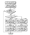
- FIG. 24 is a flowchart of an example of a specific processing procedure of the cooperative app data acquisition process according to the first embodiment.
- the setting time of the automatic JOIN channel acquired from the chat user DB 230 of the user ID by the CPU 301 and the setting time of the registered community acquired from the SNS user DB 240 of the user ID are shown in FIG. Obtained from the setting DB 250 (step S2401).
- the CPU 301 determines whether or not there is a channel or community for which the set time has elapsed since the previous acquisition (step S2402).
- step S2402 determines whether or not there is a channel or community for which the set time has elapsed since the previous acquisition.
- step S2402 determines whether or not there is a channel or community for which the set time has elapsed since the previous acquisition.
- step S2402 determines whether or not there is a channel or community for which the set time has elapsed since the previous acquisition.
- step S2402 No
- a series of processing ends without doing anything.
- step S2403 determines whether it is a chat or an SNS (step S2403).
- step S2403 In the case of chatting in step S2403 (step S2403: “chat”), the CPU 301 obtains, from the channel sentence DB 280, messages that have not been given a cooperation ID among the messages in the automatic JOIN channel so far.
- the new cooperation ID is allocated (step S2404), and the allocated new cooperation ID is recorded in the channel sentence DB 280 (step S2405).
- the CPU 301 creates a message ID, records the current date and time, the subject, the linked application name, the channel name, the text, and the linked ID in the user's mail DB 270 (step S2406).
- the process ends.
- a chat and a channel name are stored.
- a chat a channel name, a time when a message is received, the number of messages are recorded.
- step S2403 If it is an SNS in step S2403 (step S2403: “SNS”), the CPU 301 obtains, from the SNS message DB 290, a message that has not been given a cooperation ID among the messages in the registered community so far. Then, a new cooperation ID is allocated (step S2407), and the allocated new cooperation ID is recorded in the SNS message DB 290 (step S2408).
- the CPU 301 creates a message ID and records the current date and time, the subject, the linked application name, the community name, the text, and the linked ID in the user's mail DB 270 (step S2409).
- the subject is, for example, SNS and a community name.
- SNS shared secret number
- community name a community name
- message reception time a message reception time
- step S2008 all messages to which a new cooperative ID has not been assigned are acquired, and a new ID is allocated and recorded in the mail DB 270.
- step S2107 the cooperative ID is recorded.
- a message is acquired and a new ID is allocated and recorded in the mail DB 270 only when a set time has been exceeded among those not assigned a new linkage ID.
- 25 and 26 are flowcharts illustrating an example of an information processing procedure of the client terminal 202 according to the first embodiment.
- the CPU 401 determines whether or not a mail display request has been accepted by a user operation input using the keyboard 410 or the mouse 411 (step S2501).
- the CPU 401 waits to receive a mail display request (step S2501: No). If the mail display request is received by the CPU 401 (step S2501: Yes), the mail display request is transmitted to the information providing apparatus 201 (step S2502).
- the CPU 401 determines whether or not screen information of a user ID / password input screen (not shown) is received from the information providing apparatus 201 (step S2503). Here, it waits for the CPU 401 to receive the screen information of the user ID and password input screen (step S2503: No).
- step S2503 When the CPU 401 receives screen information of the user ID and password input screen (step S2503: Yes), the user ID and password input screen is displayed on the display 408 based on the received screen information. (Step S2504). Next, the CPU 401 determines whether or not an input of a user ID and a password has been received by a user operation input (step S2505).
- step S2505: No it waits for the CPU 401 to accept the input of the user ID and password.
- step S2505: Yes the CPU 401 receives input of the user ID and password (step S2505: Yes)
- the user ID and password are transmitted to the information providing apparatus 201 (step S2506).
- the CPU 401 determines whether or not screen information of an authentication error screen (not shown) has been received (step S2507).
- the CPU 401 receives the screen information of the authentication error screen (step S2507: Yes)
- the authentication error screen is displayed on the display 408 based on the received screen information (step S2508).
- a series of processing ends.
- step S2507 if the CPU 401 has not received the screen information of the authentication error screen (step S2507: No), it is determined whether the screen information of the mail list display screen has been received (step S2509). If the CPU 401 has not received the screen information of the mail list display screen (step S2509: No), the process returns to step S2507.
- step S2509 Yes
- the mail list display screen is displayed on the display 408 based on the received screen information (step S2510).
- the CPU 401 determines whether an application cooperation latest reception request has been received (step S2511).
- step S2511 when the CPU 401 receives an application cooperation latest reception request (step S2511: Yes), the application cooperation latest reception request is transmitted to the information providing apparatus 201 (step S2512), and the process proceeds to step S2509.
- step S2511: NO when the application cooperation latest reception request has not been received (step S2511: NO), the process proceeds to step S2601 shown in FIG.
- the CPU 401 determines whether or not the selection of the target mail has been accepted from the mail selection information, that is, the mail list display screen, by the user's operation input (step S2601).
- the process proceeds to step S2605.
- the mail selection information is received by the CPU 401 (step S2601: Yes)
- the mail selection information is transmitted to the information providing apparatus 201 (step S2602).
- This display request includes, for example, the user ID of the user of the client terminal 202 and the message ID of the target mail.
- the CPU 401 determines whether or not the screen information of the message display screen has been received (step S2603).
- the CPU 401 waits for reception of screen information on the message display screen (step S2603: No).
- the CPU 401 receives the screen information of the message display screen (step S2603: Yes)
- the message display screen is displayed on the display 408 based on the received screen information (step S2604).
- step S2605 determines whether or not a request for displaying the previous or subsequent message of the same application or the same channel / community has been received on the message display screen associated with the application. If a message creation screen display request has not been received (step S2605: NO), the process proceeds to step S2609.
- step S2605 when the CPU 401 accepts a message display request for the same or the same channel / community before or after (step S2605: Yes), it displays information on the message display request for the same or the same channel / community before or after. It transmits to the providing apparatus 201 (step S2606).
- the CPU 401 determines whether or not screen information on the message display screen has been received (step S2607).
- the CPU 401 waits for reception of screen information on the message display screen (step S2607: No). If the CPU 401 receives screen information on the message display screen (step S2607: Yes), the message display screen is displayed on the display 408 based on the received screen information (step S2608), and the process returns to step S2605.
- step S2609 whether or not the display request for the list display screen is requested by the CPU 401, specifically, the “return to mail list” button B4 on the message display screen 1400 in FIG. It is determined whether the “return to mail list” button B7 on the message display screen 1500 of FIG. 16 or the message display screen 1600 of FIG. 16 has been pressed (step S2609).
- the CPU 401 makes a display request for the list display screen (step S2609: Yes)
- the display request for the list display screen is transmitted to the information providing apparatus 201 (step S2610), and step S2509 in the flowchart of FIG. Migrate to
- step S2609: No If the display request for the list display screen is not issued by the CPU 401 (step S2609: No), a display end request is input by the user's operation input, specifically, the mail list display screen 1300 of FIG. 13 is input by the user's operation input. It is determined whether or not the “logout” button B3 is pressed (step S2611). If no display end request has been received (step S2611: NO), the process returns to step S2601. On the other hand, when the display end request is received by the CPU 401 (step S2611: Yes), the display end request is transmitted to the information providing apparatus 201 (step S2612), and the series of processes according to this flowchart ends.
- messages stored in other message providing systems are displayed in the same manner as emails. It is possible to avoid failing to confirm the message stored in the message providing system, and it is possible to efficiently use the message providing system, which is a plurality of communication tools, using electronic mail.
- the set time can be determined as to whether or not the message acquisition interval can be determined. Therefore, by setting the set time short, the user frequently checks messages. It becomes possible. In addition, by setting the set time longer, it is possible to eliminate the troublesomeness that the user frequently displays as mail on the mail list display screen in the same manner as other mails.
- Embodiment 2 Next, an information providing method according to the second embodiment will be described.
- the second embodiment is realized by using the setting DB 255 shown in FIG. 27 in place of the setting DB 250 shown in FIG. 8 in the information providing method described in the first embodiment. Note that illustration and description of the same parts as those described in Embodiment 1 are omitted.
- FIG. 27 is an explanatory diagram of an example of the contents stored in the setting DB 255 according to the second embodiment.
- the setting DB 250 of the first embodiment and the setting DB 255 of the second embodiment are only the difference between the “set time” field and the “set amount” field.
- the “set amount” field of the setting DB 255 the content of a channel sentence or the content of an SNS message, specifically, the number of lines, the number of messages, and the like are stored.
- step S2401 of the flowchart of FIG. 24 the amount of the stored message content is acquired, and in step S2402, the amount of the acquired message content is compared with the set amount. If the amount of statement content exceeds the set amount, the process proceeds to step S2403. If the amount of statement content does not exceed the set amount, the cooperative application data acquisition process is terminated without doing anything. Others are the same as in the first embodiment.
- both the set amount and the set time may be set as set conditions (for example, AND condition, OR condition, NOT condition, etc.).
- a message providing system that is a plurality of communication tools can be efficiently used using electronic mail.
- the content of the message (speech) is displayed as a mail on the mail list display screen when it is collected to a certain extent.
- the troublesomeness that is frequently displayed on the list display screen in the same manner as other mails can be eliminated.
- a predetermined amount is accumulated regardless of the time since the last acquisition, it will be displayed on the mail list display screen, so at an appropriate timing according to the participation status of participants to the group (for example, channel, community)
- the content of the message can be confirmed, and the stress caused by annoying users can be reduced.
- the information providing method described in the present embodiment can be realized by executing a program prepared in advance on a computer such as a personal computer or a workstation.
- the information providing program is recorded on a computer-readable recording medium such as a hard disk, a flexible disk, a CD-ROM, an MO, and a DVD, and is executed by being read from the recording medium by the computer.
- the information providing program may be distributed via a network such as the Internet.
Landscapes
- Engineering & Computer Science (AREA)
- Computer Networks & Wireless Communication (AREA)
- Signal Processing (AREA)
- Information Transfer Between Computers (AREA)
Abstract
メールプログラム(151)のみインストールされているクライアント端末(150)においても、チャットのチャンネル文やSNSメッセージの内容をメールとして通常のメールと同様にメールDBに記憶させることによって、通常のメールと同じようにメールプログラム(151)を用いて表示させることができるので、クライアント端末(150)においても、クライアント端末(100)と同様にチャットのチャンネル文やSNSメッセージの内容を確認することができる。
Description
本発明は、情報提供プログラム、情報提供装置および情報提供方法に関する。
近年、多くのユーザによって、一般的なコミュニケーションツールである電子メール(以下、「メール」という)を用いた情報の伝達をするだけでなく、チャットやSNSなど、メールとは別の多様なコミュニケーションツールであるメッセージ提供システムを用いた情報の伝達が増加している。このように、別のコミュニケーションツールを利用する場合は、それぞれ専用のアプリケーションを情報端末装置にインストールして使用する。
関連する先行技術としては、たとえば、コミュニティにおいて、自分宛、コミュニティ宛の発言を収集して、メール一覧で有無を通知したり、複数のコミュニティにおける、発言を収集し、メールで活動状況を送信するものがある(たとえば、下記特許文献1、2参照)。
しかしながら、情報端末装置の環境によっては、必ずしもそれぞれのコミュニケーションツールの専用のアプリケーションがインストールされているとは限らないため、情報端末装置によっては、別のコミュニケーションツールであるメッセージ提供システムにおけるメッセージを確認することができない場合がある。また、すべてのメッセージを確認できたとしても、コミュニケーションツールであるメッセージ提供システムが複数あることから、それらをすべて確認するのは煩わしく、また、いずれかのメッセージを確認し損なう畏れもある。
本発明は、1つの側面では、複数のコミュニケーションツールであるメッセージ提供システムを効率よく利用した情報伝達を可能にすることができる情報提供プログラム、情報提供装置および情報提供方法を提供することを目的とする。
上述した課題を解決し、目的を達成するため、本発明の一側面によれば、電子メールの表示要求を受け付け、受け付けられた電子メールの表示要求にかかる利用者の識別情報に基づいて、他のメッセージ提供システムに記憶されているメッセージを抽出し、抽出されたメッセージの内容を含む、利用者を宛先とした電子メールを作成して、利用者を差出人または宛先とした電子メールが記憶されている記憶部に記憶し、記憶部に記憶されている電子メールの内容に基づいて、電子メールの概要情報を一覧で表示するための一覧表示画面を作成し、作成された一覧表示画面を出力し、出力された一覧表示画面に一覧で表示された概要情報にかかる電子メールの選択要求を受け付け、受け付けられた選択要求にかかる電子メールの内容を記憶部から抽出し、抽出された電子メールの内容を出力する情報提供プログラム、情報提供装置および情報提供方法が提案される。
本発明の一側面によれば、複数のコミュニケーションツールであるメッセージ提供システムを電子メールを用いて効率よく利用することができるという効果を奏する。
以下に添付図面を参照して、この発明にかかる情報提供プログラム、情報提供装置および情報提供方法の実施の形態を詳細に説明する。
(実施の形態1)
図1は、実施の形態1にかかる情報提供方法の一実施例を示す説明図である。図1において、利用者は、通常、使用するクライアント端末(たとえばオフィス用PC)100に、メールプログラム101、チャットプログラム102およびSNS(Social Networking Service)プログラム103をインストールして、メール、チャットおよびSNSを利用している。
図1は、実施の形態1にかかる情報提供方法の一実施例を示す説明図である。図1において、利用者は、通常、使用するクライアント端末(たとえばオフィス用PC)100に、メールプログラム101、チャットプログラム102およびSNS(Social Networking Service)プログラム103をインストールして、メール、チャットおよびSNSを利用している。
ここで、チャットとは、複数の利用者がメッセージを設定されているチャンネルに書き込むことにより情報の伝達をおこなうコミュニケーションツールである。また、SNSとは、限定的なネットワークの中で情報交換をおこなうサービスであり、SNSを用いることによって、利用者同士のコミュニティを広げていくことができる。
また、通常使用するクライアント端末100とは別のクライアント端末(たとえばモバイル用ノートPC)150には、メールプログラム151のみをインストールしている。この場合、クライアント端末150では、メールの送受信はできるが、チャットのチャンネル文やSNSメッセージの送受信をすることはできない。
そこで、実施の形態1では、メールプログラム151のみインストールされているクライアント端末150においても、チャットのチャンネル文やSNSメッセージの内容であって利用者に関連するものを、メールとして通常のメールと同様に後述するメールDB270に記憶させることによって、通常のメールと同じようにメールプログラム151を用いて表示させることができるので、クライアント端末150においても、クライアント端末100と同様にチャットのチャンネル文やSNSメッセージの内容を確認することができる。
(メールシステム200のシステム構成例)
つぎに、実施の形態1にかかるメールシステム200のシステム構成例について説明する。図2は、実施の形態1にかかるメールシステム200のシステム構成例を示す説明図である。図2において、メールシステム200は、情報提供装置201と、複数のクライアント端末202(図面では3台)と、を含む。
つぎに、実施の形態1にかかるメールシステム200のシステム構成例について説明する。図2は、実施の形態1にかかるメールシステム200のシステム構成例を示す説明図である。図2において、メールシステム200は、情報提供装置201と、複数のクライアント端末202(図面では3台)と、を含む。
メールシステム200において、情報提供装置201および複数のクライアント端末202は、有線または無線のネットワーク210を介して相互に通信可能に接続されている。ネットワーク210は、たとえば、インターネット、LAN(Local Area Network)、WAN(Wide Area Network)などである。
ここで、情報提供装置201は、利用者認証DB(データベース)220、チャット利用者DB230、SNS利用者DB240、設定DB250、ログイン履歴DB260、メールDB270、チャンネル文DB280、SNSメッセージDB290を有し、メールシステム200内のメールの送受信をおこなうコンピュータである。情報提供装置201は、たとえば、メールサーバである。なお、利用者認証DB220、チャット利用者DB230、SNS利用者DB240、設定DB250、ログイン履歴DB260、メールDB270、チャンネル文DB280およびSNSメッセージDB290については、図5~図12を用いて後述する。
クライアント端末202は、メールの表示、作成、送受信をおこなうコンピュータである。クライアント端末202は、たとえば、メールシステム200のユーザが使用するPC(パーソナル・コンピュータ)、ノートPC、携帯電話、PDA(Personal Digital Assistant)、スマートフォン、タブレット型端末などである。メールは、たとえば、クライアント端末202のブラウザにより表示、作成、送受信されるウェブメールである。
(情報提供装置201のハードウェア構成例)
図3は、実施の形態1にかかる情報提供装置201のハードウェア構成例を示すブロック図である。図3において、情報提供装置201は、CPU(Central Processing Unit)301と、ROM(Read‐Only Memory)302と、RAM(Random Access Memory)303と、I/F(Interface)304と、磁気ディスクドライブ305と、磁気ディスク306と、光ディスクドライブ307と、光ディスク308と、入力装置309と、を有している。また、各構成部はバス300によってそれぞれ接続されている。
図3は、実施の形態1にかかる情報提供装置201のハードウェア構成例を示すブロック図である。図3において、情報提供装置201は、CPU(Central Processing Unit)301と、ROM(Read‐Only Memory)302と、RAM(Random Access Memory)303と、I/F(Interface)304と、磁気ディスクドライブ305と、磁気ディスク306と、光ディスクドライブ307と、光ディスク308と、入力装置309と、を有している。また、各構成部はバス300によってそれぞれ接続されている。
ここで、CPU301は、情報提供装置201の全体の制御を司る。ROM302は、ブートプログラムなどのプログラムを記憶している。RAM303は、CPU301のワークエリアとして使用される。I/F304は、通信回線を通じてネットワーク210に接続され、ネットワーク210を介して、クライアント端末202などの他の装置に接続される。そして、I/F304は、ネットワーク210と内部のインターフェースを司り、他の装置からのデータの入出力を制御する。I/F304には、たとえば、モデムやLANアダプタなどを採用することができる。
磁気ディスクドライブ305は、CPU301の制御にしたがって磁気ディスク306に対するデータのリード/ライトを制御する。磁気ディスク306は、磁気ディスクドライブ305の制御で書き込まれたデータを記憶する。光ディスクドライブ307は、CPU301の制御にしたがって光ディスク308に対するデータのリード/ライトを制御する。光ディスク308は、光ディスクドライブ307の制御で書き込まれたデータを記憶したり、光ディスク308に記憶されたデータをコンピュータに読み取らせたりする。
入力装置309は、文字、数字、各種指示などのデータの入力をおこなう。入力装置309は、たとえば、入力のためのキーを有するキーボードやタッチパネル式の入力パッドなどである。なお、情報提供装置201は、上述した構成部の他に、データを表示するディスプレイを有することにしてもよい。また、情報提供装置201は、たとえば、上述した構成部のうち光ディスクドライブ307および光ディスク308を有さないことにしてもよい。
(クライアント端末202のハードウェア構成例)
図4は、実施の形態1にかかるクライアント端末202のハードウェア構成例を示すブロック図である。図4において、クライアント端末202は、CPU401と、ROM402と、RAM403と、磁気ディスクドライブ404と、磁気ディスク405と、光ディスクドライブ406と、光ディスク407と、ディスプレイ408と、I/F409と、キーボード410と、マウス411と、スキャナ412と、プリンタ413と、を有している。また、各構成部はバス400によってそれぞれ接続されている。
図4は、実施の形態1にかかるクライアント端末202のハードウェア構成例を示すブロック図である。図4において、クライアント端末202は、CPU401と、ROM402と、RAM403と、磁気ディスクドライブ404と、磁気ディスク405と、光ディスクドライブ406と、光ディスク407と、ディスプレイ408と、I/F409と、キーボード410と、マウス411と、スキャナ412と、プリンタ413と、を有している。また、各構成部はバス400によってそれぞれ接続されている。
ここで、CPU401は、クライアント端末202の全体の制御を司る。ROM402は、ブートプログラムなどのプログラムを記憶している。RAM403は、CPU401のワークエリアとして使用される。磁気ディスクドライブ404は、CPU401の制御にしたがって磁気ディスク405に対するデータのリード/ライトを制御する。磁気ディスク405は、磁気ディスクドライブ404の制御で書き込まれたデータを記憶する。
光ディスクドライブ406は、CPU401の制御にしたがって光ディスク407に対するデータのリード/ライトを制御する。光ディスク407は、光ディスクドライブ406の制御で書き込まれたデータを記憶したり、光ディスク407に記憶されたデータをコンピュータに読み取らせたりする。
ディスプレイ408は、カーソル、アイコンあるいはツールボックスをはじめ、文書、画像、機能情報などのデータを表示する。ディスプレイ408は、たとえば、CRT、TFT液晶ディスプレイ、プラズマディスプレイ、有機ELディスプレイなどを採用することができる。
I/F409は、通信回線を通じてネットワーク210に接続され、ネットワーク210を介して情報提供装置201などの他の装置に接続される。そして、I/F409は、ネットワーク210と内部のインターフェースを司り、他の装置からのデータの入出力を制御する。I/F409には、たとえば、モデムやLANアダプタなどを採用することができる。
キーボード410は、文字、数字、各種指示などの入力のためのキーを備え、データの入力をおこなう。また、タッチパネル式の入力パッドやテンキーなどであってもよい。マウス411は、カーソルの移動や範囲選択、あるいはウィンドウの移動やサイズの変更などをおこなう。ポインティングデバイスとして同様に機能を備えるものであれば、タッチパネル、トラックボールやジョイスティックなどであってもよい。
スキャナ412は、画像を光学的に読み取り、クライアント端末202内に画像データを取り込む。なお、スキャナ412は、OCR(Optical Character Reader)機能を持たせてもよい。また、プリンタ413は、画像データや文書データを印刷する。プリンタ413には、たとえば、レーザプリンタやインクジェットプリンタを採用することができる。なお、クライアント端末202は、たとえば、上述した構成部のうち、光ディスクドライブ406、光ディスク407、スキャナ412、プリンタ413などを有さないことにしてもよい。
(各種DB220、230、240、250、260、270、280、290の記憶内容)
つぎに、図5~図12を用いて、情報提供装置201が有する各種DB220、230、240、250、260、270、280、290の記憶内容について説明する。各種DB220、230、240、250、260、270、280、290は、たとえば、図3に示した情報提供装置201のRAM303、磁気ディスク306、光ディスク308などの記憶装置により実現される。
つぎに、図5~図12を用いて、情報提供装置201が有する各種DB220、230、240、250、260、270、280、290の記憶内容について説明する。各種DB220、230、240、250、260、270、280、290は、たとえば、図3に示した情報提供装置201のRAM303、磁気ディスク306、光ディスク308などの記憶装置により実現される。
<利用者認証DB220の記憶内容>
図5は、実施の形態1にかかる利用者認証DB220の記憶内容の一例を示す説明図である。図5において、利用者認証DB220は、少なくとも、「利用者ID」、「パスワード」のフィールドを有し、各フィールドに情報を設定することで、各利用者の認証情報(たとえば、認証情報500-1~500-3)をレコードとして記憶している。
図5は、実施の形態1にかかる利用者認証DB220の記憶内容の一例を示す説明図である。図5において、利用者認証DB220は、少なくとも、「利用者ID」、「パスワード」のフィールドを有し、各フィールドに情報を設定することで、各利用者の認証情報(たとえば、認証情報500-1~500-3)をレコードとして記憶している。
ここで、利用者IDは、メールシステム200の利用者の識別子である。パスワードは、メールシステム200の利用者を認証する符号である。たとえば、認証情報500-1は、利用者ID「yamada@xxx.ww」の利用者のパスワード「kljkfapdojaf」を示している。本実施の形態においては、利用者ID「yamada@xxx.ww」は、後述するメールDB270の「メッセージID」および「宛先」としても用いられる。
<チャット利用者DB230の記憶内容>
図6は、実施の形態1にかかるチャット利用者DB230の記憶内容の一例を示す説明図である。図6において、チャット利用者DB230は、少なくとも、「利用者ID」、「チャットID」、「自動JOINチャンネル」、「現在JOINチャンネル」のフィールドを有し、各フィールドに情報を設定することで、各チャット利用者情報(たとえば、チャット利用者情報600-1~600-5)を記憶している。
図6は、実施の形態1にかかるチャット利用者DB230の記憶内容の一例を示す説明図である。図6において、チャット利用者DB230は、少なくとも、「利用者ID」、「チャットID」、「自動JOINチャンネル」、「現在JOINチャンネル」のフィールドを有し、各フィールドに情報を設定することで、各チャット利用者情報(たとえば、チャット利用者情報600-1~600-5)を記憶している。
ここで、利用者IDは、図5に示した利用者認証DB220と同様に、メールシステム200の利用者の識別子である。チャットIDは、チャットにおける利用者の識別子であり、利用者IDと1対1で対応する。自動JOINチャンネルは、後述する連携アプリデータ記録処理においてチャンネル文DB280から自動的にメッセージ(発言)を取得するために、利用者IDに対応させてあらかじめ登録しているチャンネルである。
現在JOINチャンネルは、現在、利用者IDにかかる利用者が参加しているチャンネルに関する情報である。したがって、利用者は、現在JOINチャンネルの中から、自動的にメッセージをメールとして取得したいチャンネルを自動JOINチャンネルとして登録している。
たとえば、チャット利用者情報600-1は、利用者ID「yamada@xxx.ww」の利用者のチャットIDが「yamada」であり、自動JOINチャンネルが「健康管理」であり、現在JOINチャンネルが「健康管理、平成22年会」であることを示している。自動JOINチャンネル、現在JOINチャンネルの全部または一部は、各利用者の所定の操作によって、追加、変更、削除することができる。
<SNS利用者DB240の記憶内容>
図7は、実施の形態1にかかるSNS利用者DB240の記憶内容の一例を示す説明図である。図7において、SNS利用者DB240は、少なくとも「利用者ID」、「ニックネーム」、「アイコン」、「登録コミュニティ」のフィールドを有し、各フィールドに情報を設定することで、各SNS利用者情報(たとえば、SNS利用者情報700-1~700-5)を記憶している。
図7は、実施の形態1にかかるSNS利用者DB240の記憶内容の一例を示す説明図である。図7において、SNS利用者DB240は、少なくとも「利用者ID」、「ニックネーム」、「アイコン」、「登録コミュニティ」のフィールドを有し、各フィールドに情報を設定することで、各SNS利用者情報(たとえば、SNS利用者情報700-1~700-5)を記憶している。
ここで、利用者IDは、図5に示した利用者認証DB220、図6に示したチャット利用者DB230と同様に、メールシステム200の利用者の識別子である。ニックネームは、SNSにおける利用者の識別情報であり、利用者IDと1対1で対応する。アイコンは、利用者のメッセージに付与される画像(イラスト、写真など)であって、利用者のメッセージと他の利用者のメッセージとを容易に視覚的に区別可能にするものである。
登録コミュニティは、チャット利用者DB230の自動JOINチャンネルと同様に、後述する連携アプリデータ記録処理において、SNSメッセージDB290から自動的にメッセージ(発言)を取得するために、利用者IDに対応させてあらかじめ登録しているチャンネルである。
たとえば、SNS利用者情報700-1は、利用者ID「yamada@xxx.ww」の利用者のニックネームが「やまだ」であり、アイコンは男性のイラスト画像であり、登録コミュニティが「教育コミュニティ」であることを示している。登録コミュニティの全部または一部は、各利用者の所定の操作によって、追加、変更、削除することができる。
<設定DB250の記憶内容>
図8は、実施の形態1にかかる設定DB250の記憶内容の一例を示す説明図である。図8において、設定DB250は、少なくとも「アプリ(アプリケーション)名」、「チャンネル名/コミュニティ名」、「設定時間」のフィールドを有し、各フィールドに情報を設定することで、各利用者ごとの設定情報(たとえば、設定情報800-1~800-7)を記憶している。ここで、設定情報800-1~800-4が、チャットのチャンネルに関する設定であり、設定情報800-5~800-7が、SNSのコミュニティに関する設定である。
図8は、実施の形態1にかかる設定DB250の記憶内容の一例を示す説明図である。図8において、設定DB250は、少なくとも「アプリ(アプリケーション)名」、「チャンネル名/コミュニティ名」、「設定時間」のフィールドを有し、各フィールドに情報を設定することで、各利用者ごとの設定情報(たとえば、設定情報800-1~800-7)を記憶している。ここで、設定情報800-1~800-4が、チャットのチャンネルに関する設定であり、設定情報800-5~800-7が、SNSのコミュニティに関する設定である。
設定時間は、後述する連携アプリデータ取得処理において、チャンネル文DB280またSNSメッセージDB290から自動的にメッセージ(発言)を取得する際に取得の可否を決定するための時間である。したがって、CPU301は、前回の取得してからの時間が、この設定時間を経過している場合に、チャンネル文DB280またはSNSメッセージDB290から取得し、この設定時間を経過していない場合は取得しない。設定時間の設定は、分単位、時間単位に限らず、日単位、週単位などでもおこなうことができる。
設定時間は、同じチャンネル、コミュニティであっても、利用者ごとに設定することができ、また、利用者または管理者の所定の操作によって変更することができる。したがって、各チャンネル、コミュニティにおいて、設定時間を短く設定することで、利用者はメッセージを頻繁にチェックすることが可能となる。また、設定時間を長く設定することで、利用者がメールとして頻繁にメール一覧表示画面に他のメールと同様に表示される煩わしさを解消することができる。
<ログイン履歴DB260の記憶内容>
図9は、実施の形態1にかかるログイン履歴DB260の記憶内容の一例を示す説明図である。図9において、ログイン履歴DB260は、「ログイン日時」、「ログアウト日時」のフィールドを有し、各フィールドに日時情報を設定することで、各利用者のメールシステム200へのログイン履歴情報を記憶している。図9においては、このログイン履歴DB260は、各利用者ごとに設けられているように示している。また、図9において、図示を省略する「利用者ID」のフィールドをさらに設けて、利用者ごとに管理できるようにしてもよい。
図9は、実施の形態1にかかるログイン履歴DB260の記憶内容の一例を示す説明図である。図9において、ログイン履歴DB260は、「ログイン日時」、「ログアウト日時」のフィールドを有し、各フィールドに日時情報を設定することで、各利用者のメールシステム200へのログイン履歴情報を記憶している。図9においては、このログイン履歴DB260は、各利用者ごとに設けられているように示している。また、図9において、図示を省略する「利用者ID」のフィールドをさらに設けて、利用者ごとに管理できるようにしてもよい。
図9において、ログイン履歴情報900-1からは、利用者が「2012/2/10 8:34:23」(2012年2月10日8時34分23秒)にメールシステム200へログインし、「2012/2/10 20:23:24」(2012年2月10日20時23分24秒)にメールシステム200からログアウトしたことがわかる。また、ログイン履歴情報900-3では、利用者が「2012/2/20 15:32:01」(2012年2月20日15時32分01秒)にメールシステム200へログインしたことがわかり、「ログアウト日時」のフィールドに日時情報が記憶されていない。このことから、利用者が現在ログイン中であることがわかる。
<メールDB270の記憶内容>
図10は、実施の形態1にかかるメールDB270の記憶内容の一例を示す説明図である。図10において、メールDB270は、少なくとも「送受信情報」、「メッセージID」、「発信者ID」、「発信日時」、「宛先」、「件名」、「連携アプリ(アプリケーション)名」、「チャンネル名/コミュニティ名」、「本文」、「連携ID」のフィールドを有する。各フィールドに情報を設定することで、メール情報(たとえば、メール情報1000-1~1000-7)が記憶されている。
図10は、実施の形態1にかかるメールDB270の記憶内容の一例を示す説明図である。図10において、メールDB270は、少なくとも「送受信情報」、「メッセージID」、「発信者ID」、「発信日時」、「宛先」、「件名」、「連携アプリ(アプリケーション)名」、「チャンネル名/コミュニティ名」、「本文」、「連携ID」のフィールドを有する。各フィールドに情報を設定することで、メール情報(たとえば、メール情報1000-1~1000-7)が記憶されている。
図10のメールDB270において、メール情報のうち、メール情報1000-1、1000-4、1000-5は通常のメールであり、メール情報1000-2、1000-3、1000-6、1000-7は連携アプリである。
図10において、メールDB270は、各利用者ごとに設けられているように示しているが、複数の利用者について、共通のデータベースにおける「発信者ID」および「宛先」などのフィールド、あるいは図示を省略する他に設けられたフィールドから、利用者ごとに区別して管理できるようにしてもよい。したがって、図10は、「発信者ID」および「宛先」のフィールドから利用者IDである『yamada@xxx.ww』に該当する情報のみをメールDB270から収集したものであるとすることもできる。
送受信情報は、受信メール(『受信』)か送信メール(『送信』)かを区別する情報である。メッセージIDは、メールシステム200にて送受信されたメールを一意に識別する識別子である。通常は全体としてユニークな文字列となればよいが、一般的に、@マークの右側をドメイン名とし、左側は発信日時や利用者IDなどを使い、何らかの規則で作成した文字列とすることで、全体としてユニークな文字列となるようにしている。本実施例では、メールを識別しやすいような文字列としている。
図10のメールDB270において、メール情報1000-2、1000-3、1000-5、1000-6、1000-7が受信メールであり、メール情報1000-1、1000-4が送信メールである。
発信者IDは、メールの送信元の識別子であり、たとえば、送信元となるユーザの利用者IDである。発信日時は、メールの発信日時である。宛先は、メールの宛先であり、たとえば、メールの送信先となるユーザのメールアドレスである。宛先は、たとえば、CC(Carbon Copy)やBCC(Blind Carbon Copy)を含む。
件名は、メールの件名である。件名は、後述する図13に示す一覧表示画面1300にメールの概要情報の一部として表示される。連携アプリ(アプリケーション)名は、連携する他のメッセージ提供システムに関する情報である。具体的には、『チャット』はチャット提供システム(チャットアプリケーション)であり、チャット利用者DB230、チャンネル文DB280を参照したことを示しており、『SNS』はSNS提供システム(SNSアプリケーション)であり、SNS利用者DB240、SNSメッセージDB290を参照したことを示している。図10のメールDB270において、連携アプリのメール情報1000-3、1000-6、1000-7がチャットである。また、連携アプリのメール情報1000-2がSNSである。
チャンネル名/コミュニティ名は、チャット利用者DB230において自動JOINチャンネルに記憶されているチャンネル名またはSNS利用者DB240において登録コミュニティに記憶されているコミュニティ名である。本文は、メールの本文情報として記述されたメッセージである。連携アプリの場合は、定型文(たとえば『チャット:○○コミュニティからの連携です。hh:mm-HH:MMまでの○件です。』、『SNS:○○コミュニティからの連携です。hh:mm-HH:MMまでの○件です。』)の後に、チャンネル文DB280またはSNSメッセージDB290から抽出された発言内容が本文情報となる。
連携IDは、後述するチャンネル文DB280、SNSメッセージDB290から抽出された連携IDと一致する。連携IDの内容については、後述する。
このように、「連携アプリ名」、「チャンネル名/コミュニティ名」、「連携ID」は、アプリ連携のメールにのみデータが記憶され、連携アプリではない通常のメールには、「連携アプリ名」、「チャンネル名/コミュニティ名」、「連携ID」は記憶されない。
たとえば、メール情報1000-1は、利用者IDが『yamada@xxx.ww』のユーザの送信メールに関する情報である。メールの「送受信情報」は『送信』、「メッセージID」は『system2@xxx.ww』、「発信者ID」は『yamada@xxx.ww』、「発信日時」は『2011/2/20 16:39:29』、「宛先」は『tanaka@xxx.ww』、「件名」は『○○システムの障害』、「本文」は『山田です。・・・』である。そして、このメール情報1000-1は、通常のメールなので、「連携アプリ名」、「チャンネル名/コミュニティ名」および「連携ID」の各フィールドには情報は入っていない。
また、メール情報1000-2は、利用者IDが『yamada@xxx.ww』のユーザの受信メールに関する情報である。メールの「送受信情報」は『受信』、「メッセージID」は『apprenkei3@xxx.ww』、「発信者ID」は『アプリ連携』、「発信日時」は『2011/2/20 16:32:32』、「宛先」は『yamada@xxx.ww』、「件名」は『SNS:教育コミュニティ』、「連携アプリ名」は『SNS』、「チャンネル名/コミュニティ名」は『教育』、「本文」は『SNS:教育コミュニティからの連携です。・・・』、「連携ID」は『SNS00001』である。
また、メール情報1000-3も、利用者IDが『yamada@xxx.ww』のユーザの受信メールに関する情報である。メールの「送受信情報」は『受信』、「メッセージID」は『apprenkei2@xxx.ww』、「発信者ID」は『アプリ連携』、「発信日時」は『2011/2/20 16:32:07』、「宛先」は『yamada@xxx.ww』、「件名」は『チャット:健康管理チャンネル』、「連携アプリ名」は『チャット』、「チャンネル名/コミュニティ名」は『健康管理』、「本文」は『チャット:健康管理チャンネルからの連携です。・・・』、「連携ID」は『CH00002』である。
<チャンネル文DB280の記憶内容>
図11は、実施の形態1にかかるチャンネル文DB280の記憶内容の一例を示す説明図である。図11において、チャンネル文DB280は、チャットにおけるチャンネル文情報を記憶するデータベースであり、少なくとも「チャンネル名」、「発信日時」、「チャットID」、「発言内容」、「連携ID」のフィールドを有し、各フィールドに情報を設定することで、チャンネル文情報(たとえば、チャンネル文情報1100-1~1100-13)をレコードとして記憶している。チャンネル文情報は、図11に示すように、各チャンネル名ごとに管理してもよい。
図11は、実施の形態1にかかるチャンネル文DB280の記憶内容の一例を示す説明図である。図11において、チャンネル文DB280は、チャットにおけるチャンネル文情報を記憶するデータベースであり、少なくとも「チャンネル名」、「発信日時」、「チャットID」、「発言内容」、「連携ID」のフィールドを有し、各フィールドに情報を設定することで、チャンネル文情報(たとえば、チャンネル文情報1100-1~1100-13)をレコードとして記憶している。チャンネル文情報は、図11に示すように、各チャンネル名ごとに管理してもよい。
発信日時は、発言の発信日時である。チャットIDは、チャットにおける利用者の識別子である。チャットIDのフィールドの情報は、チャット利用者DB230のチャットIDのフィールドの情報と対応する。これによって、チャンネル文情報の利用者IDを特定することができる。発言内容は、利用者が発言したメッセージの内容である。
連携IDは、アプリ連携としてチャンネル文情報が抽出される際に、付与される識別子である。複数のチャンネル文情報が同時に抽出される場合は、同時に抽出される複数のチャンネル文情報に同一の連携IDがそれぞれに付与され、記憶される。この連携IDが付与されているか否かによって、チャンネル文がすでに抽出されたか未抽出であるかを判断することができる。また、連携IDの違いによって、チャンネル文がどのタイミングで抽出されたかを判断することができる。連携IDは、アプリ連携のメール情報としてメールDB270「連携ID」のフィールドに記憶される。
<SNSメッセージDB290の記憶内容>
図12は、実施の形態1にかかるSNSメッセージDB290の記憶内容の一例を示す説明図である。図12において、SNSメッセージDB290は、SNSにおけるSNSメッセージ情報を記憶するデータベースであり、少なくとも「コミュニティ名」、「発信日時」、「SNSニックネーム」、「発言内容」、「連携ID」のフィールドを有し、各フィールドに情報を設定することで、SNSメッセージ情報(たとえば、メッセージ情報1200-1~1200-3)をレコードとして記憶している。SNSメッセージ情報は、図12に示すように、各コミュニティ名ごとに管理してもよい。
図12は、実施の形態1にかかるSNSメッセージDB290の記憶内容の一例を示す説明図である。図12において、SNSメッセージDB290は、SNSにおけるSNSメッセージ情報を記憶するデータベースであり、少なくとも「コミュニティ名」、「発信日時」、「SNSニックネーム」、「発言内容」、「連携ID」のフィールドを有し、各フィールドに情報を設定することで、SNSメッセージ情報(たとえば、メッセージ情報1200-1~1200-3)をレコードとして記憶している。SNSメッセージ情報は、図12に示すように、各コミュニティ名ごとに管理してもよい。
発信日時は、発言の発信日時である。SNSニックネームは、SNSにおける利用者の識別情報である。SNSニックネームのフィールドの情報は、SNS利用者DB240のニックネームのフィールドの情報と対応する。これによって、SNSメッセージ情報の利用者IDを特定することができる。発言内容は、利用者が発言したメッセージの内容である。
連携IDは、アプリ連携としてSNSメッセージ情報が抽出される際に、付与される識別子である。複数のSNSメッセージ情報が同時に抽出される場合は、同時に抽出される複数のSNSメッセージ情報に同一の連携IDがそれぞれに付与され、記憶される。この連携IDが付与されているか否かによって、SNSメッセージがすでに抽出されたか未抽出であるかを判断することができる。また、連携IDの違いによって、SNSメッセージがどのタイミングで抽出されたかを判断することができる。連携IDは、アプリ連携のメール情報としてメールDB270の「連携ID」のフィールドに記憶される。
(メール一覧表示画面の画面例)
つぎに、図4に示したクライアント端末202のディスプレイ408に表示されるメール一覧表示画面について説明する。メール一覧表示画面の画面情報は、たとえば、情報提供装置201で作成され、クライアント端末202に送信される。
つぎに、図4に示したクライアント端末202のディスプレイ408に表示されるメール一覧表示画面について説明する。メール一覧表示画面の画面情報は、たとえば、情報提供装置201で作成され、クライアント端末202に送信される。
図13は、実施の形態1にかかるメール一覧表示画面の画面例を示す説明図である。利用者がメール一覧表示画面の表示要求をすると、ディスプレイ408に図13に示すメール一覧表示画面1300が表示される。図13において、メール一覧表示画面1300には、利用者ID「yamada@xxx.ww」の利用者宛に送信されたメールおよび利用者ID「yamada@xxx.ww」の利用者が送信したメールの概要情報(たとえば、概要情報1300-1~1300-7)が表示されている。
また、メール一覧表示画面1300には、「メッセージ作成」ボタンB1と、「アプリ連携最新受信」ボタンB2と、「ログアウト」ボタンB3とが備えられている。「メッセージ作成」ボタンB1がクリックされると、新規メールを作成するメッセージ作成画面の表示要求が情報提供装置201に送信された結果、図示を省略するメッセージ作成画面がディスプレイ408に表示される。
「アプリ連携最新受信」ボタンB2は、後述する図21のフローチャートのステップS2101に対応し、「アプリ連携最新受信」ボタンB2がクリックされると、後述する図20のフローチャートのステップS2008の連携アプリ記録処理(後述する図23のフローチャート参照)が実行され、アプリ連携の最新情報を含む、更新されたメール一覧表示画面1300がディスプレイ408に表示される。「ログアウト」ボタンB3がクリックされると、ログアウト要求が情報提供装置201に送信された結果、メール一覧表示画面1300の表示が終了する。
図13において、メール一覧表示画面1300には、利用者ID「yamada@xxx.ww」のユーザ宛に送信されたメールおよび利用者ID「yamada@xxx.ww」が差出人となっているメールの概要情報(たとえば、概要情報1300-1~1300-7)が表示されている。
概要情報は、メールの差出人、発信日時および件名を示す情報である。ここでは、メールの差出人として、メールの発信者IDが示されている。また、メールの件名として、メールのタイトルが示されている。たとえば、概要情報1300-1は、メールの差出人「yamada@xxx.ww」、発信日時「2011/2/20 16:39:29」および件名「○○システムの障害」を示している。
また、たとえば、概要情報1300-2は、メールの差出人「アプリ連携」、発信日時「2011/2/20 16:32:32」および件名「SNS:教育コミュニティ」を示している。また、たとえば、概要情報1300-3は、メールの差出人「アプリ連携」、発信日時「2011/2/20 16:32:07」および件名「チャット:健康管理チャンネル」を示している。
各概要情報は、図13に示すように、通常のメール、チャットのアプリ連携、SNSのアプリ連携ごとに表示の仕方、たとえば文字色やフォントを変えたり、背景色を変えるなどすることにより、それぞれを容易に区別できるようにしてもよい。また、図示を省略するが、通常のメール、チャットのアプリ連携、SNSのアプリ連携ごとに並べ替えができるようにしてもよい。
メール一覧表示画面1300において、図4に示したキーボード410やマウス411を用いたユーザの操作入力により、メール一覧表示画面1300に表示される図示を省略するカーソルを移動させていずれかの概要情報がクリックされると、該概要情報に対応するメールが選択された状態となる。
(メッセージ表示画面の画面例)
つぎに、クライアント端末202のディスプレイ408に表示されるメッセージ表示画面について説明する。図14~図16は、実施の形態1にかかるメッセージ表示画面の画面例を示す説明図である。
つぎに、クライアント端末202のディスプレイ408に表示されるメッセージ表示画面について説明する。図14~図16は、実施の形態1にかかるメッセージ表示画面の画面例を示す説明図である。
図13のメール一覧表示画面1300において、利用者が概要情報1300-2の表示要求をすると、ディスプレイ408に図14に示すSNSのメッセージ表示画面1400が表示される。
図14において、「メール一覧に戻る」ボタンB4は、後述する図22のフローチャートのステップS2204に対応している。「メール一覧に戻る」ボタンB4がクリックされると、ステップS2107の連携アプリデータ取得処理(後述する図24のフローチャート参照)が実行され、更新されたメール一覧表示画面1300がディスプレイ408に表示される。
「前の教育コミュニティメッセージ」の矢印ボタンB5および「次の教育コミュニティメッセージ」の矢印ボタンB6は、後述する図22のフローチャートのステップS2203に対応している。矢印ボタンB5またはB6がクリックされると、ステップS2205によって前/後の連携IDをメールDB270から取得して、取得された連携IDが付与されたメッセージを含むメッセージ表示画面1400(図示省略)がディスプレイ408に表示される。
図13のメール一覧表示画面1300において、利用者が概要情報1300-7の表示要求をすると、ディスプレイ408に図15に示すチャットのメッセージ表示画面1500が表示される。
図15において、「メール一覧に戻る」ボタンB7は、図14に示した「メール一覧に戻る」ボタンB4と同じ機能を有する。「前の健康管理チャンネルメッセージ」の矢印ボタンB8、「次の健康管理チャンネルメッセージ」の矢印ボタンB9も、「前の教育コミュニティメッセージ」の矢印ボタンB5、「次の教育コミュニティメッセージ」の矢印ボタンB6と同様の機能を有する。
図15のメッセージ表示画面1500において、利用者が「次の健康管理チャンネルメッセージ」の矢印ボタンB9を押下すると、ディスプレイ408に図16に示すSNSのメッセージ表示画面1600が表示される。図13のメール一覧表示画面1300において、利用者が概要情報1300-3の表示要求をしても同様に、ディスプレイ408に図16に示すチャットのメッセージ表示画面1600が表示される。
図16において、「メール一覧に戻る」ボタンB7、「前の健康管理チャンネルメッセージ」の矢印ボタンB8、「次の健康管理チャンネルメッセージ」の矢印ボタンB9のそれぞれのボタンは、図15におけるメッセージ表示画面1500と同様の機能を有する。
また、図14~図16のメッセージ表示画面1400~1600には、図13に示したメール一覧表示画面1300において設けた「ログアウト」ボタンB3が設けられてはいないが、それぞれのメッセージ表示画面1400~1600において、「ログアウト」ボタンB3と同様の「ログアウト」ボタンを設けるようにしてもよい。そうすることで、メッセージ表示画面1400~1600から、一端、メール一覧表示画面1300へ戻らなくても、直接ログアウトすることができる。
(情報提供装置201の機能的構成例)
図17は、実施の形態1にかかる情報提供装置201の機能的構成例を示すブロック図である。図17において、情報提供装置201は、受付部1701と、メッセージ抽出部1702と、メール作成部1703と、メール記憶部1704と、一覧表示画面作成部1705と、出力部1706と、メール抽出部1707と、を含む。受付部1701~メール抽出部1707は、制御部となる機能であり、具体的には、たとえば、図3に示したROM302、RAM303、磁気ディスク306、光ディスク308などの記憶装置に記憶されたプログラムをCPU301に実行させることにより、または、I/F304により、その機能を実現する。
図17は、実施の形態1にかかる情報提供装置201の機能的構成例を示すブロック図である。図17において、情報提供装置201は、受付部1701と、メッセージ抽出部1702と、メール作成部1703と、メール記憶部1704と、一覧表示画面作成部1705と、出力部1706と、メール抽出部1707と、を含む。受付部1701~メール抽出部1707は、制御部となる機能であり、具体的には、たとえば、図3に示したROM302、RAM303、磁気ディスク306、光ディスク308などの記憶装置に記憶されたプログラムをCPU301に実行させることにより、または、I/F304により、その機能を実現する。
受付部1701は、所定のアドレス宛に送信されたメールあるいは所定のアドレスから送信されたメールの表示要求を受け付ける機能を有する。ここで、所定のアドレスとは、メールシステム200にてメールを送受信する際にユーザを特定するための文字列であり、たとえば、ユーザのメールアドレスである。所定のアドレスは、1ユーザに対して複数存在していてもよい。
また、メールの表示要求には、たとえば、要求元となるユーザの利用者IDと、表示要求の対象となるメールのメッセージIDとが含まれている。利用者IDは、たとえば、ユーザのメールアドレスである。
具体的には、たとえば、受付部1701が、対象となるメールの表示要求をクライアント端末202から受信することにより、当該メールの表示要求を受け付ける。また、受付部1701が、たとえば、図3に示した入力装置309を用いたユーザの操作入力により、当該メールの表示要求を受け付けることにしてもよい。
また、受付部1701は、利用者認証処理をおこなうようにしてもよい。具体的には、たとえば、図示を省略する利用者ID、パスワード入力画面の画面情報をクライアント端末202に送信し、利用者IDおよびパスワードを受信した場合に、図5に示した利用者認証DB220を参照して、利用者IDおよびパスワードが一致するか否かを判断することによって、利用者の認証処理を実行する。そして、受付部1701は、利用者が認証された場合には、図9に示したログイン履歴DB260にログイン日時を記憶する。
メッセージ抽出部1702は、受付部1701によって受け付けられたメールの表示要求にかかるアドレスに対応する利用者の識別情報に基づいて、他のメッセージ提供システムに記憶されているメッセージを抽出する。具体的には、メッセージ抽出部1702は、たとえば、利用者の識別情報に基づいて、他のメッセージ提供システムに記憶されているメッセージのうち、当該利用者が参加しているグループにおけるメッセージのみを抽出する。
より具体的には、たとえば、メッセージ抽出部1702は、図6に示したチャット利用者DB230から、ここで、利用者IDに対応する自動JOINチャンネルを抽出する。利用者IDが「yamada@xxx.ww」であれば、自動JOINチャンネル「健康管理」が抽出される。そして、メッセージ抽出部1702は、抽出された「健康管理」に該当するチャンネル名「健康管理」のチャンネル文情報をチャンネル文DB280から抽出する。
その際、メッセージ抽出部1702は、前回の抽出後にチャンネル文DB280に記憶されたメッセージのみを抽出するようにするとよい。具体的には、メッセージ抽出部1702は、たとえば、チャンネル文DB280における、抽出された「健康管理」に該当するチャンネル名「健康管理」のチャンネル文情報の中から、連携IDが設定されていないチャンネル文情報のみを抽出するようにしてもよい。
また、メッセージ抽出部1702は、前回の抽出後から今回の表示要求までの時間が、あらかじめ設定された設定時間を経過している場合に、他のメッセージ提供システムに記憶されているメッセージを抽出するようにしてもよい。具体的には、メッセージ抽出部1702は、たとえば、図8に示した、設定DB250から、設定時間を取得し、前回の抽出後から今回の表示要求までの時間と当該設定時間とを比較して、前回の抽出後から今回の表示要求までの時間が当該設定時間を超えている場合にのみ、メッセージを抽出するようにしてもよい。
より具体的には、メッセージ抽出部1702は、チャンネル名「健康管理」の設定時間は「1時間」であるので、前回の抽出から1時間経過後になっている場合にのみ、上記メールの抽出処理をおこなうようにしてもよい。
また、同様に、メッセージ抽出部1702は、図7に示したSNS利用者DB240から、利用者IDに対応する登録コミュニティを抽出する。ここで、利用者IDが「yamada@xxx.ww」であれば、登録コミュニティ「教育コミュニティ」が抽出される。そして、メッセージ抽出部1702は、抽出された「教育コミュニティ」に該当するコミュニティ名「教育コミュニティ」のSNSメッセージ情報をSNSメッセージDB290から抽出する。
その際、メッセージ抽出部1702は、前回の抽出後にSNSメッセージDB290に記憶されたメッセージのみを抽出するようにするとよい。具体的には、メッセージ抽出部1702は、たとえば、SNSメッセージDB290における、抽出された「教育コミュニティ」に該当するコミュニティ名「教育コミュニティ」のSNSメッセージ情報の中から、連携IDが設定されていないSNSメッセージ情報のみを抽出するようにしてもよい。
また、メッセージ抽出部1702は、前回の抽出後から今回の表示要求までの時間が、あらかじめ設定された設定時間を経過している場合に、他のメッセージ提供システムに記憶されているメッセージを抽出するようにしてもよい。具体的には、メッセージ抽出部1702は、たとえば、図8に示した、設定DB250から、設定時間を取得し、前回の抽出後から今回の表示要求までの時間と当該設定時間とを比較して、前回の抽出後から今回の表示要求までの時間が当該設定時間を超えている場合にのみ、メッセージを抽出するようにしてもよい。
より具体的には、メッセージ抽出部1702は、コミュニティ名「教育コミュニティ」の設定時間は「1時間」であるので、前回の抽出から1時間が経過している場合にのみ、上記メールの抽出処理をおこなうようにしてもよい。
メール作成部1703は、抽出されたメッセージの内容を含む、利用者を宛先としたメール(連携アプリデータ)を作成する。具体的には、メール作成部1703は、メッセージIDをあらたに作成し、メールDB270に対して、作成されたメッセージIDを記憶し、宛先に当該利用者の宛先を設定(記憶)し、件名に提携の文書を設定(記憶)し、連携アプリ名を記憶し、チャンネル名/コミュニティ名を記憶し、本文に抽出されたメッセージの内容を登録(記憶)し、連携IDを記憶する。このようにすることによって、連携アプリデータが、通常のメールと同様に、メールDB270に記憶される。
メール記憶部1704は、前記利用者を差出人または宛先としたメールが記憶される。メール記憶部1704は、たとえば、図10に示したメールDB270によってその機能を実現することができる。
一覧表示画面作成部1705は、メール記憶部1704に記憶されているメールの内容に基づいて、当該メールの概要情報からなる前記利用者用のメールの一覧表示画面を作成する。具体的には、たとえば、メールDB270から、発信者ID、発信日時、件名を抽出し、所定のフォーマットによりメール情報を一覧表示する画面(具体的には、たとえば図13に示したメール一覧表示画面1300)を作成する。
出力部1706は、一覧表示画面作成部1705によって作成された一覧表示画面を出力する。具体的には、クライアント端末202へ一覧表示画面の情報を送信して、図4に示したクライアント端末202のディスプレイ408に当該一覧表示画面を表示する。
また、受付部1701は、出力部1706によって出力された一覧表示画面に一覧で表示された概要情報にかかるメールの選択要求を受け付ける。具体的には、メール一覧表示画面1300において、図4に示したキーボード410やマウス411を用いたユーザの操作入力により、メール一覧表示画面1300に表示される図示を省略するカーソルを移動させていずれかの概要情報がクリックされることによって、該概要情報に対応するメールが選択され、その情報をクライアント端末202から受信することによってメールの選択要求を受け付ける。
メール抽出部1707は、受け付けられた選択要求にかかるメールの内容をメール記憶部1704から抽出する。具体的には、たとえば、受け付けた選択要求にかかるメッセージIDのメール情報をメールDB270から抽出する。また、出力部1706は、抽出されたメールの内容を出力する。具体的には、クライアント端末202へメッセージ表示画面(具体的には、たとえば図14に示したメッセージ表示画面1400、図15に示したメッセージ表示画面1500)の情報を送信して、クライアント端末202のディスプレイ408に当該一覧表示画面を表示する。
(情報提供装置201の情報提供処理手順)
つぎに、実施の形態1にかかる情報提供装置201の情報提供処理手順について説明する。図18は、実施の形態1にかかる情報提供装置201の情報提供処理(チャットプログラム)手順の一例を示すフローチャートである。
つぎに、実施の形態1にかかる情報提供装置201の情報提供処理手順について説明する。図18は、実施の形態1にかかる情報提供装置201の情報提供処理(チャットプログラム)手順の一例を示すフローチャートである。
図18のフローチャートにおいて、まず、CPU301により、自動JOINチャンネル名に参加している他の参加者のチャットIDを、図6に示したチャット利用者DB230から取得する(ステップS1801)。そして、CPU301により、自動JOINチャンネルに参加者を含めたチャット画面を作成し、クライアント端末202へ送信する(ステップS1802)。
つぎに、CPU301により、新規チャンネル名称とチャンネル作成要求をクライアント端末202から受信したか否かを判断する(ステップS1803)。ここで、CPU301により、新規チャンネル名称とチャンネル作成要求を受信しなかった場合(ステップS1803:No)は、ステップS1808へ移行する。一方、CPU301により、新規チャンネル名称とチャンネル作成要求をクライアント端末202から受信した場合(ステップS1803:Yes)は、図11に示したチャンネル文DB280に、新規チャンネル名に対応する欄を追加する(ステップS1804)。
そして、CPU301により、チャット利用者DB230におけるその利用者IDの現在JOINチャンネルにその新規チャンネル名を記憶し(ステップS1805)、新規作成したチャンネルを、チャット画面に追加する(ステップS1806)。その後、CPU301により、そのチャット画面(図示省略)をクライアント端末202へ送信する(ステップS1807)。
つぎに、CPU301により、チャンネルへの参加要求をクライアント端末202から受信したか否かを判断する(ステップS1808)。ここで、チャンネルへの参加要求を受信しなかった場合(ステップS1808:No)は、ステップS1812へ移行する。一方、CPU301により、チャンネルへの参加要求を受信した場合(ステップS1808:Yes)は、CPU301により、チャット利用者DB230におけるその利用者IDの現在JOINチャンネルに当該チャンネル名を記憶し(ステップS1809)、当該チャンネルを、チャット画面に追加する(ステップS1810)。その後、CPU301により、そのチャット画面(図示省略)をクライアント端末202へ送信する(ステップS1811)。
つぎに、CPU301により、あるチャンネル宛へのメッセージをクライアント端末202から受信したか否かを判断する(ステップS1812)。ここで、メッセージを受信しなかった場合(ステップS1812:No)は、ステップS1817へ移行する。一方、CPU301により、当該チャンネル宛へのメッセージを受信した場合(ステップS1812:Yes)は、当該チャンネルに対応するチャンネル文DB280に発言者とメッセージを記憶する(ステップS1813)。
そして、CPU301により、チャット利用者DB230から、当該チャンネルを現在JOINチャンネルとして持つチャットIDを検出する(ステップS1814)。つぎに、CPU301により、検出したチャットIDに対応するチャット画面の、当該チャンネル欄にメッセージを追加する(ステップS1815)。その後、CPU301により、そのチャット画面(図示省略)をクライアント端末202へ送信する(ステップS1816)。
つぎに、CPU301により、終了要求をクライアント端末202から受信したか否かを判断する(ステップS1817)。ここで、終了要求を受信しなかった場合(ステップS1817:No)は、ステップS1803へ移行する。一方、終了要求を受信した場合(ステップS1817:Yes)は、本フローチャートの一連の処理を終了する。
図19は、実施の形態1にかかる情報提供装置201の情報提供処理(SNSプログラム)手順の一例を示すフローチャートである。図19のフローチャートにおいて、まず、CPU301により、図7に示したSNS利用者DB240から、利用者の登録コミュニティを取得する(ステップS1901)。そして、CPU301により、図12に示したSNSメッセージDB290の、取得されたコミュニティに対応するメッセージを取得してコミュニティ画面を作成し、作成されたコミュニティ画面(図示省略)をクライアント端末202へ送信する(ステップS1902)。
つぎに、CPU301により、コミュニティへの参加要求をクライアント端末202から受信したか否かを判断する(ステップS1903)。ここで、コミュニティへの参加要求を受信しなかった場合(ステップS1903:No)は、ステップS1906へ移行する。一方、CPU301により、コミュニティへの参加要求を受信した場合(ステップS1903:Yes)は、利用者のSNS利用者DB240の登録コミュニティに、指定されたコミュニティ名を記憶し(ステップS1904)、SNSメッセージDB290の、当該コミュニティに対応するメッセージを取得してコミュニティ画面を作成し、作成されたコミュニティ画面(図示省略)をクライアント端末202へ送信する(ステップS1905)。
つぎに、CPU301により、あるコミュニティ宛へのメッセージをクライアント端末202から受信したか否かを判断する(ステップS1906)。ここで、メッセージを受信しなかった場合(ステップS1906:No)は、ステップS1908へ移行する。一方、CPU301により、当該コミュニティ宛へのメッセージを受信した場合(ステップS1906:Yes)は、SNSメッセージDB290の、当該コミュニティに対応する欄に発言者とメッセージを記憶する(ステップS1907)。
つぎに、CPU301により、終了要求をクライアント端末202から受信したか否かを判断する(ステップS1908)。ここで、終了要求を受信しなかった場合(ステップS1908:No)は、ステップS1903へ移行する。一方、終了要求を受信した場合(ステップS1908:Yes)は、本フローチャートの一連の処理を終了する。
図20~図22は、実施の形態1にかかる情報提供装置201の情報提供処理手順の一例を示すフローチャートである。図20のフローチャートにおいて、まず、CPU301により、メール表示要求をクライアント端末202から受信したか否かを判断する(ステップS2001)。ここで、CPU301により、メール表示要求を受信するのを待つ(ステップS2001:No)。そして、CPU301により、メール表示要求を受信した場合(ステップS2001:Yes)は、利用者ID、パスワード入力画面(図示省略)の画面情報をクライアント端末202に送信する(ステップS2002)。つぎに、CPU301により、利用者ID、パスワードをクライアント端末202から受信したか否かを判断する(ステップS2003)。
ここで、CPU301により、利用者IDおよびパスワードを受信するのを待つ(ステップS2003:No)。そして、CPU301により、利用者IDおよびパスワードを受信した場合(ステップS2003:Yes)は、図5に示した利用者認証DB220を参照して、利用者の認証処理を実行する(ステップS2004)。
具体的には、たとえば、CPU301が、利用者認証DB220を参照して、受信した利用者IDに対応するパスワードを特定する。そして、CPU301が、受信したパスワードと、特定したパスワードとの一致判定をおこなう。この結果、CPU301は、パスワードが一致する場合、CPU301が利用者を認証する。一方、パスワードが不一致の場合、CPU301が利用者を認証しない。
つぎに、CPU301により、利用者が認証されたか否かを判断する(ステップS2005)。ここで、ユーザが認証されなかった場合(ステップS2005:No)は、CPU301により、認証エラー画面(図示省略)の画面情報をクライアント端末202に送信して(ステップS2006)、本フローチャートによる一連の処理を終了する。
一方、ステップS2005において、ユーザが認証された場合(ステップS2005:Yes)は、CPU301により、図9に示したログイン履歴DB260のログイン欄に認証された時刻を記録する(ステップS2007)。そして、CPU301により、連携アプリデータ記録処理を実行する(ステップS2008)。ステップS2008の連携アプリデータ記録処理の内容については、図23を用いて後に説明する。
その後、図10に示した受信した利用者IDのメールDB270に基づいて、図13に示したメール一覧表示画面1300を作成する(ステップS2009)。具体的には、「発信者ID」、「宛先」の少なくともいずれかのフィールドの情報が利用者IDの情報と一致するメール情報を抽出し、抽出したメール情報に基づいて、メール一覧表示画面の画面情報を作成する。この際、CPU301が、メールの発生日時が新しい順にソートされたメール一覧表示画面の画面情報を作成することにしてもよい。
そして、CPU301により、メール一覧表示画面の画面情報をクライアント端末202に送信する(ステップS2010)。このクライアント端末202は、ステップS2001において受信されたメール一覧表示画面の表示要求の要求元のクライアント端末202である。
その後、CPU301により、表示終了要求をクライアント端末202から受信したか否かを判断する(ステップS2011)。表示終了要求は、たとえば、図13に示したメール一覧表画面1300の「ログアウト」ボタンB3を利用者が押下することによっておこなうことができる。ここで、終了要求を受信しなかった場合(ステップS2011:No)は、図21のフローチャートのステップS2101へ移行する。一方、終了要求を受信した場合(ステップS2011:Yes)は、CPU301により、図9に示したログイン履歴DB260のログアウト欄に終了要求を受信した時刻を記録し(ステップS2012)、一連の処理を終了する。
つぎに、図21のフローチャートにおいて、CPU301により、アプリ連携最新受信要求をクライアント端末202から受信したか否かを判断する(ステップS2101)。アプリ連携最新受信要求は、たとえば、図13に示したメール一覧表示画面1300の「アプリ連携最新受信」ボタンB2を利用者が押下することによっておこなうことができる。ここで、アプリ連携最新受信要求を受信した場合(ステップS2101:Yes)は、図20のフローチャートのステップS2008へ移行し、ステップS2008以降の処理を繰り返し実行する。
ステップS2101において、アプリ連携最新受信要求を受信しなかった場合(ステップS2101:No)は、つぎに、CPU301により、メール選択情報、すなわち図13に示したメール一覧表示画面1300に一覧表示されている概要情報の中の所定のメッセージの表示要求をクライアント端末202から受信したか否かを判断する(ステップS2102)。ここで、CPU301により、メール選択情報を受信していない場合(ステップS2102:No)は、ステップS2106へ移行する。
一方、CPU301により、メール選択情報を受信した場合(ステップS2102:Yes)、選択されたメールがアプリ連携メールか否かを判断する(ステップS2103)。選択されたメールがアプリ連携メールか否かは、図10に示したメールDB270の「連携アプリ名」のフィールドに『SNS』または『チャット』の情報が記憶されているか否かで判断する。メールDB270の「連携アプリ名」のフィールドに『SNS』または『チャット』の情報が記憶されていれば、アプリ連携メールであると判断し、いずれの情報も記録されていなければ、アプリ連携メールでない(すなわち、通常のメールである)と判断する。
ステップS2103において、選択されたメールがアプリ連携メールである場合(ステップS2103:Yes)は、図22のフローチャートのステップS2201へ移行する。一方、CPU301により、選択されたメールがアプリ連携メールでない場合(ステップS2103:No)は、選択されたメールの本文、発信日時などをメールDB270から取得する(ステップS2104)。そして、CPU301により、本文、発信日時などを含めたメッセージ表示画面(図示省略)を作成し、作成したメッセージ表示画面の画面情報をクライアント端末202に送信する(ステップS2105)。
その後、CPU301により、一覧表示画面の表示要求をクライアント端末202から受信するのを待って(ステップS2106:No)、CPU301により、一覧表示画面の表示要求を受信した場合(ステップS2106:Yes)は、連携アプリデータ取得処理を実行する(ステップS2107)。ステップS2106の連携アプリデータ取得処理の内容については図24を用いて後に説明する。そして、ステップS2107の連携アプリデータ取得処理の後に、図20のフローチャートのステップS2009へ移行し、ステップS2009以降の処理を繰り返し実行する。
引き続き、ステップS2103において、選択されたメールがアプリ連携メールである場合(ステップS2103:Yes)の処理の手順を説明する。図22のフローチャートにおいて、CPU301により、選択されたメールの連携IDを図10に示したメールDB270から取得する(ステップS2201)。
そして、取得された連携IDに対する図11に示したチャンネル文DB280の情報または図12に示したSNSメッセージDB290の情報を用いて、図14または図15に示すようなメッセージの表示画面を作成し、CPU301によりクライアント端末202へ送信する(ステップS2202)。
つぎに、CPU301により、クライアント端末202から、前/後のチャンネル/コミュニティのメッセージ表示要求を受信したか否かを判断する(ステップS2203)。前のチャンネルのメッセージ表示要求は、たとえば図15の「前の健康管理チャンネルメッセージ」の矢印ボタンB8を利用者が押下することによっておこなうことができる。また、後のチャンネルのメッセージ表示要求は、たとえば図15の「次の健康管理チャンネルメッセージ」の矢印ボタンB9を利用者が押下することによっておこなうことができる。
同様に、前のコミュニティのメッセージ表示要求は、たとえば図14の「前の教育コミュニティメッセージ」の矢印ボタンB5を利用者が押下することによっておこなうことができる。また、後のコミュニティのメッセージ表示要求は、たとえば図14の「次の教育コミュニティメッセージ」の矢印ボタンB6を利用者が押下することによっておこなうことができる。
ステップS2203において、CPU301により、クライアント端末202から、前/後のチャンネル/コミュニティのメッセージ表示要求を受信した場合(ステップS2203:Yes)は、前/後の連携IDをメールDB270から取得し(ステップS2205)、ステップS2202へ戻り、以後ステップS2202以降の処理を繰り返し実行する。
具体的には、図10のメールDB270において、連携IDが「CH00001」に対するチャンネル文DB280の情報を用いてメッセージの表示画面が作成されていた場合に、前のチャンネルのメッセージ表示要求を受信した場合は、連携IDが「CH00000」に対するチャンネル文DB280の情報を用いたメッセージの表示画面が作成され、後のチャンネルのメッセージ表示要求を受信した場合は、連携IDが「CH00002」に対するチャンネル文DB280の情報を用いたメッセージの表示画面が作成されることになる。
ステップS2203において、前/後のチャンネル/コミュニティのメッセージ表示要求を受信しなかった場合(ステップS2203:No)は、CPU301により、クライアント端末202から、一覧表示画面の表示要求を受信したか否かを判断する(ステップS2204)。ここで、一覧表示画面の表示要求を受信しなかった場合(ステップS2204:No)は、ステップS2203へ戻る。一方、一覧表示画面の表示要求を受信した場合(ステップS2204:Yes)は、図21に示したステップS2107へ移行する。
これにより、利用者からの各種表示要求に対して、メール一覧表示画面、メッセージ作成画面およびメッセージ表示画面の画面情報をクライアント端末202に提供することができる。
(連携アプリデータ記録処理)
つぎに、図20のステップS2008における連携アプリデータ記録処理の手順について説明する。図23は、実施の形態1にかかる連携アプリデータ記録処理の具体的処理手順の一例を示すフローチャートである。図23のフローチャートにおいて、CPU301により、利用者IDのチャット利用者DB230から、自動JOINチャンネルを取得する(ステップS2301)。
つぎに、図20のステップS2008における連携アプリデータ記録処理の手順について説明する。図23は、実施の形態1にかかる連携アプリデータ記録処理の具体的処理手順の一例を示すフローチャートである。図23のフローチャートにおいて、CPU301により、利用者IDのチャット利用者DB230から、自動JOINチャンネルを取得する(ステップS2301)。
自動JOINチャンネルが複数あれば、それらすべての自動JOINチャンネルを取得する。たとえば利用者IDが「yamada@xxx.ww」であれば、自動JOINチャンネルとして「健康管理」を取得し、利用者IDが「tanaka@xxx.ww」であれば、自動JOINチャンネルとして「テニスクラブ」、「特許相談」、「健康管理」の3つを取得する。
同様にして、CPU301により、利用者IDのSNS利用者DB240から、登録コミュニティを取得する(ステップS2302)。登録コミュニティが複数あれば、それらすべての登録コミュニティを取得する。たとえば利用者IDが「yamada@xxx.ww」であれば、登録コミュニティとして「教育コミュニティ」を取得し、利用者IDが「suzuki@xxx.ww」であれば、自動JOIN登録コミュニティとして「教育コミュニティ」、「特許コミュニティ」の2つを取得する。
つぎに、CPU301により、今までの自動JOINチャンネルでの発言のうち、連携IDが付与されていない発言を、チャンネル文DB280から取得して、新しい連携IDを割り振り(ステップS2303)、割り振られた新しい連携IDをチャンネル文DB280に記録する(ステップS2304)。
そして、CPU301により、メッセージIDを作成して、現在日時と、件名と、連携アプリ名と、チャンネル名と、本文と、連携IDとを利用者のメールDB270に記録する(ステップS2305)。ここで、件名には、たとえばチャットであること、およびチャンネル名を記憶する。また本文には、たとえばチャットであること、チャンネル名、メッセージを受信した時刻、メッセージの件数などを記録する。
また、CPU301により、今までの登録コミュニティでの発言のうち、連携IDが付与されていない発言を、SNSメッセージDB290から取得して、新しい連携IDを割り振り(ステップS2306)、割り振られた新しい連携IDをSNSメッセージDB290に記録する(ステップS2307)。
そして、CPU301により、メッセージIDを作成して、現在日時と、件名と、連携アプリ名と、コミュニティ名と、本文と、連携IDとを利用者のメールDB270に記録する(ステップS2308)。ここで、件名には、たとえばSNSであること、およびコミュニティ名を記憶する。また本文には、たとえばSNSであること、コミュニティ名、メッセージを受信した時刻、メッセージの件数などを記録する。これにより、ステップS2008の連携アプリデータ記録処理を終了する。
(連携アプリデータ取得処理)
つぎに、図21のステップS2107における連携アプリデータ取得処理の手順について説明する。図24は、実施の形態1にかかる連携アプリデータ取得処理の具体的処理手順の一例を示すフローチャートである。図24のフローチャートにおいて、CPU301により、利用者IDのチャット利用者DB230から取得した自動JOINチャンネルの設定時間、利用者IDのSNS利用者DB240から取得した登録コミュニティの設定時間を、図8に示した設定DB250から取得する(ステップS2401)。
つぎに、図21のステップS2107における連携アプリデータ取得処理の手順について説明する。図24は、実施の形態1にかかる連携アプリデータ取得処理の具体的処理手順の一例を示すフローチャートである。図24のフローチャートにおいて、CPU301により、利用者IDのチャット利用者DB230から取得した自動JOINチャンネルの設定時間、利用者IDのSNS利用者DB240から取得した登録コミュニティの設定時間を、図8に示した設定DB250から取得する(ステップS2401)。
つぎに、CPU301により、前の取得時から設定時間を経過しているチャンネル、コミュニティが存在するか否かを判断する(ステップS2402)。ここで、設定時間を超えていない場合(ステップS2402:No)は、何もせずに、一連の処理を終了する。一方、設定時間を超えている場合(ステップS2402:Yes)は、チャットであるかあるいはSNSであるかを判断する(ステップS2403)。
ステップS2403で、チャットである場合(ステップS2403:「チャット」)は、CPU301により、今までの自動JOINチャンネルでの発言のうち、連携IDが付与されていない発言を、チャンネル文DB280から取得して、新しい連携IDを割り振り(ステップS2404)、割り振られた新しい連携IDをチャンネル文DB280に記録する(ステップS2405)。
そして、CPU301により、メッセージIDを作成して、現在日時と、件名と、連携アプリ名と、チャンネル名と、本文と、連携IDとを利用者のメールDB270に記録し(ステップS2406)、一連の処理を終了する。ここで、件名には、たとえばチャットであること、およびチャンネル名を記憶する。また本文には、たとえばチャットであること、チャンネル名、メッセージを受信した時刻、メッセージの件数などを記録する。
一方、ステップS2403で、SNSである場合(ステップS2403:「SNS」)は、CPU301により、今までの登録コミュニティでの発言のうち、連携IDが付与されていない発言を、SNSメッセージDB290から取得して、新しい連携IDを割り振り(ステップS2407)、割り振られた新しい連携IDをSNSメッセージDB290に記録する(ステップS2408)。
そして、CPU301により、メッセージIDを作成して、現在日時と、件名と、連携アプリ名と、コミュニティ名と、本文と、連携IDとを利用者のメールDB270に記録する(ステップS2409)。ここで、件名には、たとえばSNSであること、およびコミュニティ名を記憶する。また本文には、たとえばSNSであること、コミュニティ名、メッセージを受信した時刻、メッセージの件数などを記録する。これにより、ステップS2107の連携アプリデータ取得処理を終了する。
このように、ステップS2008の連携アプリデータ記録処理においては、新しい連携IDが付与されていないすべてのメッセージを取得して新しいIDを割り振り、メールDB270に記録するが、これに対してステップS2107の連携アプリデータ取得処理においては、新しい連携IDが付与されていないもののうち、設定時間を超えている場合にのみ、メッセージを取得して新しいIDを割り振り、メールDB270に記録する。
したがって、設定時間を超えていない場合は、たとえメッセージが存在しても新しい連携IDは割り振られず、メールDB270に記録されることはない。これによって、チャットまたはSNSのメッセージを受信するたびに頻繁にメールの対象となることを回避することができる。
(クライアント端末202の情報処理手順)
つぎに、実施の形態1にかかるクライアント端末202の情報処理手順について説明する。図25および図26は、実施の形態1にかかるクライアント端末202の情報処理手順の一例を示すフローチャートである。図25のフローチャートにおいて、まず、CPU401により、キーボード410やマウス411を用いたユーザの操作入力により、メール表示要求を受け付けたか否かを判断する(ステップS2501)。
つぎに、実施の形態1にかかるクライアント端末202の情報処理手順について説明する。図25および図26は、実施の形態1にかかるクライアント端末202の情報処理手順の一例を示すフローチャートである。図25のフローチャートにおいて、まず、CPU401により、キーボード410やマウス411を用いたユーザの操作入力により、メール表示要求を受け付けたか否かを判断する(ステップS2501)。
ここで、CPU401により、メール表示要求を受け付けるのを待つ(ステップS2501:No)。そして、CPU401により、メール表示要求を受け付けた場合(ステップS2501:Yes)は、メール表示要求を情報提供装置201に送信する(ステップS2502)。
つぎに、CPU401により、情報提供装置201から利用者ID、パスワードの入力画面(図示省略)の画面情報を受信したか否かを判断する(ステップS2503)。ここで、CPU401により、利用者ID、パスワードの入力画面の画面情報を受信するのを待つ(ステップS2503:No)。
そして、CPU401により、利用者ID、パスワードの入力画面の画面情報を受信した場合(ステップS2503:Yes)は、受信した画面情報に基づいて、ディスプレイ408に利用者ID、パスワードの入力画面を表示する(ステップS2504)。つぎに、CPU401により、ユーザの操作入力により利用者IDおよびパスワードの入力を受け付けたか否かを判断する(ステップS2505)。
ここで、CPU401により、利用者IDおよびパスワードの入力を受け付けるのを待つ(ステップS2505:No)。そして、CPU401により、利用者IDおよびパスワードの入力を受け付けた場合(ステップS2505:Yes)は、利用者IDおよびパスワードを情報提供装置201に送信する(ステップS2506)。
つぎに、CPU401により、認証エラー画面(図示省略)の画面情報を受信したか否かを判断する(ステップS2507)。ここで、CPU401により、認証エラー画面の画面情報を受信した場合(ステップS2507:Yes)は、受信した画面情報に基づいて、ディスプレイ408に認証エラー画面を表示して(ステップS2508)、本フローチャートによる一連の処理を終了する。
ステップS2507において、CPU401により、認証エラー画面の画面情報を受信していない場合(ステップS2507:No)、メール一覧表示画面の画面情報を受信したか否かを判断する(ステップS2509)。ここで、CPU401により、メール一覧表示画面の画面情報を受信していない場合(ステップS2509:No)、ステップS2507へ戻る。
一方、CPU401により、メール一覧表示画面の画面情報を受信した場合(ステップS2509:Yes)、受信した画面情報に基づいて、ディスプレイ408にメール一覧表示画面を表示する(ステップS2510)。つぎに、CPU401により、アプリ連携最新受信要求を受け付けたか否かを判断する(ステップS2511)。
ステップS2511において、CPU401により、アプリ連携最新受信要求を受け付けた場合(ステップS2511:Yes)は、アプリ連携最新受信要求を情報提供装置201へ送信し(ステップS2512)、ステップS2509へ移行する。一方、アプリ連携最新受信要求を受け付けなかった場合(ステップS2511:No)は、図26に示すステップS2601へ移行する。
図26のフローチャートにおいて、まず、CPU401により、ユーザの操作入力によりメール選択情報、すなわちメール一覧表示画面の中から対象メールの選択を受け付けたか否かを判断する(ステップS2601)。ここで、対象メールの選択を受け付けていない場合(ステップS2601:No)、ステップS2605へ移行する。
一方、CPU401により、メール選択情報を受け付けた場合(ステップS2601:Yes)、メール選択情報を情報提供装置201に送信する(ステップS2602)。この表示要求には、たとえば、クライアント端末202のユーザの利用者IDと、対象メールのメッセージIDとが含まれている。
つぎに、CPU401により、メッセージ表示画面の画面情報を受信したか否かを判断する(ステップS2603)。ここで、CPU401により、メッセージ表示画面の画面情報を受信するのを待つ(ステップS2603:No)。そして、CPU401により、メッセージ表示画面の画面情報を受信した場合(ステップS2603:Yes)は、受信した画面情報に基づいて、ディスプレイ408にメッセージ表示画面を表示する(ステップS2604)。
つぎに、CPU401により、アプリ連携のメッセージ表示画面にて、前あるいは後の同アプリ、同チャンネル/コミュニティのメッセージの表示要求を受け付けたか否かを判断する(ステップS2605)。ここで、メッセージ作成画面の表示要求を受け付けていない場合(ステップS2605:No)、ステップS2609へ移行する。
一方、CPU401により、前あるいは後の同アプリ、同チャンネル/コミュニティのメッセージの表示要求を受け付けた場合(ステップS2605:Yes)、前あるいは後の同アプリ、同チャンネル/コミュニティのメッセージの表示要求を情報提供装置201に送信する(ステップS2606)。
つぎに、CPU401により、メッセージ表示画面の画面情報を受信したか否かを判断する(ステップS2607)。ここで、CPU401により、メッセージ表示画面の画面情報を受信するのを待つ(ステップS2607:No)。そして、CPU401により、メッセージ表示画面の画面情報を受信した場合(ステップS2607:Yes)は、受信した画面情報に基づいて、ディスプレイ408にメッセージ表示画面を表示し(ステップS2608)、ステップS2605へ戻る。
つぎに、ステップS2609において、CPU401により、一覧表示画面の表示要求があったか否か、具体的には、ユーザの操作入力により図14のメッセージ表示画面1400の「メール一覧に戻る」ボタンB4または図15のメッセージ表示画面1500、図16のメッセージ表示画面1600の「メール一覧に戻る」ボタンB7が押下されたか否かを判断する(ステップS2609)。ここで、CPU401により、一覧表示画面の表示要求があった場合(ステップS2609:Yes)は、一覧表示画面の表示要求を情報提供装置201へ送信し(ステップS2610)、図25のフローチャートのステップS2509へ移行する。
そして、CPU401により、一覧表示画面の表示要求がなかった場合(ステップS2609:No)は、ユーザの操作入力により表示終了要求、具体的には、ユーザの操作入力により図13のメール一覧表示画面1300の「ログアウト」ボタンB3が押下されたか否かを判断する(ステップS2611)。ここで、表示終了要求を受け付けていない場合(ステップS2611:No)、ステップS2601へ戻る。一方、CPU401により、表示終了要求を受け付けた場合(ステップS2611:Yes)、表示終了要求を情報提供装置201に送信して(ステップS2612)、本フローチャートによる一連の処理を終了する。
以上説明したように、実施の形態1にかかる情報提供装置201によれば、他のメッセージ提供システムに記憶されているメッセージをメールと同様に表示されるので、メールを閲覧するだけで、他のメッセージ提供システムに記憶されているメッセージを確認し損なうことを回避することができ、複数のコミュニケーションツールであるメッセージ提供システムを電子メールを用いて効率よく利用することができる。
また、実施の形態1にかかる情報提供装置201によれば、メッセージの取得間隔に関する可否について設定時間を定めることができるので、設定時間を短く設定することで、利用者はメッセージを頻繁にチェックすることが可能となる。また、設定時間を長く設定することで、利用者がメールとして頻繁にメール一覧表示画面に他のメールと同様に表示される煩わしさを解消することができる。
(実施の形態2)
つぎに、実施の形態2にかかる情報提供方法について説明する。実施の形態2では、実施の形態1で説明した情報提供方法において、図8に示した設定DB250に代えて、図27に示す設定DB255を用いることによって実現する。なお、実施の形態1で説明した箇所と同様の箇所については図示および説明を省略する。
つぎに、実施の形態2にかかる情報提供方法について説明する。実施の形態2では、実施の形態1で説明した情報提供方法において、図8に示した設定DB250に代えて、図27に示す設定DB255を用いることによって実現する。なお、実施の形態1で説明した箇所と同様の箇所については図示および説明を省略する。
図27は、実施の形態2にかかる設定DB255の記憶内容の一例を示す説明図である。実施の形態1の設定DB250と、実施の形態2の設定DB255とは、「設定時間」のフィールドと「設定量」のフィールドの違いのみである。設定DB255の「設定量」のフィールドには、チャンネル文の発言内容またはSNSメッセージの発言内容の量、具体的には、行数、メッセージ数などを記憶する。
そして、図示を省略するが、図24のフローチャートのステップS2401において、記憶されている発言内容の量を取得し、ステップS2402において、取得された発言内容の量と設定量と比較し、当該設定量を超えているか否かを判断し、発言内容の量が当該設定量を超えている場合に、ステップS2403へ移行する。発言内容の量が当該設定量を超えてない場合には、何もせずに連携アプリデータ取得処理を終了する。その他は、実施の形態1と同じである。
また、実施の形態2にかかる設定量と、実施の形態1にかかる設定時間とを、利用者が自由に選択して設定することができる。また、設定量と設定時間の両方を設定条件(たとえばAND条件、OR条件、NOT条件など)として設定するようにしてもよい。
以上説明したように、実施の形態2にかかる情報提供方法によれば、実施の形態1と同様に、複数のコミュニケーションツールであるメッセージ提供システムを電子メールを用いて効率よく利用することができる。
さらに、実施の形態2にかかる情報提供方法によれば、メッセージ(発言)の内容が、ある程度まとまった時点で、メールとしてメール一覧表示画面に表示されるので、メッセージが登録されるごとにメールとして頻繁に一覧表示画面に他のメールと同様に表示される煩わしさを解消することができる。また、前回取得されてからの時間に関係なく所定量が貯まった場合にメール一覧表示画面に表示されるので、グループ(たとえばチャンネル、コミュニティ)に対する参加者の参加状況に応じた適切なタイミングで、メッセージの内容を確認することができ、利用者に煩わしさから来るストレスを軽減することができる。
なお、本実施の形態で説明した情報提供方法は、あらかじめ用意されたプログラムをパーソナル・コンピュータやワークステーション等のコンピュータで実行することにより実現することができる。本情報提供プログラムは、ハードディスク、フレキシブルディスク、CD-ROM、MO、DVD等のコンピュータで読み取り可能な記録媒体に記録され、コンピュータによって記録媒体から読み出されることによって実行される。また、本情報提供プログラムは、インターネット等のネットワークを介して配布してもよい。
200 メールシステム
201 情報提供装置
202 クライアント端末
1701 受付部
1702 メッセージ抽出部
1703 メール作成部
1704 メール記憶部
1705 一覧表示画面作成部
1706 出力部
1707 メール抽出部
201 情報提供装置
202 クライアント端末
1701 受付部
1702 メッセージ抽出部
1703 メール作成部
1704 メール記憶部
1705 一覧表示画面作成部
1706 出力部
1707 メール抽出部
Claims (9)
- コンピュータに、
電子メールの表示要求を受け付け、
受け付けられた前記電子メールの表示要求にかかる利用者の識別情報に基づいて、他のメッセージ提供システムに記憶されているメッセージを抽出し、
抽出された前記メッセージの内容を含む、前記利用者を宛先とした電子メールを作成して、前記利用者を差出人または宛先とした電子メールが記憶されている記憶部に記憶し、
前記記憶部に記憶されている電子メールの内容に基づいて、電子メールの概要情報を一覧で表示するための一覧表示画面を作成し、
作成された一覧表示画面を出力し、
出力された一覧表示画面に一覧で表示された概要情報にかかる電子メールの選択要求を受け付け、
受け付けられた選択要求にかかる電子メールの内容を前記記憶部から抽出し、
抽出された電子メールの内容を出力する、
処理を実行させることを特徴とする情報提供プログラム。 - 前記メッセージを抽出する処理は、前回の抽出後に前記他のメッセージ提供システムに記憶されたメッセージを抽出することを特徴とする請求項1に記載の情報提供プログラム。
- 前記メッセージを抽出する処理は、前回の抽出後から今回の表示要求までの時間が、あらかじめ設定された設定時間を経過している場合に、前記他のメッセージ提供システムに記憶されているメッセージを抽出することを特徴とする請求項1または2に記載の情報提供プログラム。
- 前記メッセージを抽出する処理は、前回の抽出後に前記他のメッセージ提供システムに記憶されたメッセージの量が所定値を超えている場合に、当該他のメッセージ提供システムに記憶されているメッセージを抽出することを特徴とする請求項1または2に記載の情報提供プログラム。
- 前記メッセージを抽出する処理は、前記他のメッセージ提供システムに記憶されているメッセージのうち、前記利用者の識別情報に基づいて、前記利用者が登録されているグループにおけるメッセージを抽出することを特徴とする請求項1~4のいずれか一つに記載の情報提供プログラム。
- 前記他のメッセージ提供システムが、チャンネルごとにメッセージを記憶するチャット提供システムであり、
前記メッセージを抽出する処理は、
前記チャット提供システムに記憶されているメッセージのうち、前記利用者の識別情報に基づいて、前記利用者が登録されているチャンネルにおけるメッセージを抽出することを特徴とする請求項5に記載の情報提供プログラム。 - 前記他のメッセージ提供システムが、コミュニティごとにメッセージを記憶するSNS(Social Networking Service)提供システムであり、
前記メッセージを抽出する処理は、
前記SNS提供システムに記憶されているメッセージのうち、前記利用者の識別情報に基づいて、前記利用者が登録されているコミュニティにおけるメッセージを抽出することを特徴とする請求項5に記載の情報提供プログラム。 - 電子メールの表示要求を受け付ける表示要求受付部と、
前記表示要求受付部によって受け付けられた前記電子メールの表示要求にかかる利用者の識別情報に基づいて、他のメッセージ提供システムに記憶されているメッセージを抽出する抽出部と、
前記抽出部によって抽出された前記メッセージの内容を含む、前記利用者を宛先とした電子メールを作成する電子メール作成部と、
前記電子メール作成部によって作成された前記利用者を差出人または宛先とした電子メールを記憶する記憶部と、
前記記憶部に記憶されている電子メールの内容に基づいて、電子メールの概要情報を一覧で表示するための一覧表示画面を作成する一覧表示画面作成部と、
前記一覧表示画面作成部によって作成された一覧表示画面を出力する一覧表示画面出力部と、
前記一覧表示画面出力部によって出力された一覧表示画面に一覧で表示された概要情報にかかる電子メールの選択要求を受け付ける選択要求受付部と、
前記選択要求受付部によって受け付けられた選択要求にかかる電子メールの内容を前記記憶部から抽出する電子メール抽出部と、
前記電子メール抽出部によって抽出された電子メールの内容を出力する内容出力部と、
を有することを特徴とする情報提供装置。 - コンピュータが、
電子メールの表示要求を受け付け、
受け付けられた前記電子メールの表示要求にかかる利用者の識別情報に基づいて、他のメッセージ提供システムに記憶されているメッセージを抽出し、
抽出された前記メッセージの内容を含む、前記利用者を宛先とした電子メールを作成して、前記利用者を差出人または宛先とした電子メールが記憶されている記憶部に記憶し、
前記記憶部に記憶されている電子メールの内容に基づいて、電子メールの概要情報を一覧で表示するための一覧表示画面を作成し、
作成された一覧表示画面を出力し、
出力された一覧表示画面に一覧で表示された概要情報にかかる電子メールの選択要求を受け付け、
受け付けられた選択要求にかかる電子メールの内容を前記記憶部から抽出し、
抽出された電子メールの内容を出力する、
処理を実行することを特徴とする情報提供方法。
Applications Claiming Priority (2)
| Application Number | Priority Date | Filing Date | Title |
|---|---|---|---|
| JP2012-075234 | 2012-03-28 | ||
| JP2012075234A JP6056170B2 (ja) | 2012-03-28 | 2012-03-28 | 情報提供プログラム、情報提供装置および情報提供方法 |
Publications (1)
| Publication Number | Publication Date |
|---|---|
| WO2013145450A1 true WO2013145450A1 (ja) | 2013-10-03 |
Family
ID=49258783
Family Applications (1)
| Application Number | Title | Priority Date | Filing Date |
|---|---|---|---|
| PCT/JP2012/081625 WO2013145450A1 (ja) | 2012-03-28 | 2012-12-06 | 情報提供プログラム、情報提供装置および情報提供方法 |
Country Status (2)
| Country | Link |
|---|---|
| JP (1) | JP6056170B2 (ja) |
| WO (1) | WO2013145450A1 (ja) |
Cited By (2)
| Publication number | Priority date | Publication date | Assignee | Title |
|---|---|---|---|---|
| JP2017182328A (ja) * | 2016-03-29 | 2017-10-05 | 株式会社Nttドコモ | 情報処理装置、情報処理方法及びプログラム |
| JP7463434B2 (ja) | 2015-02-03 | 2024-04-08 | Lineヤフー株式会社 | 端末、端末の制御方法、及びプログラム |
Families Citing this family (3)
| Publication number | Priority date | Publication date | Assignee | Title |
|---|---|---|---|---|
| KR101685226B1 (ko) * | 2012-06-12 | 2016-12-20 | 라인 가부시키가이샤 | 메신저 플랫폼의 인간 관계를 기반으로 하는 소셜 그래프를 활용한 메신저 연계 서비스 시스템 및 방법 |
| WO2016060093A1 (ja) * | 2014-10-13 | 2016-04-21 | 和田 哲也 | ソーシャル情報処理プログラム、ソーシャル情報処理装置、及びソーシャル情報処理方法 |
| JP6780177B1 (ja) * | 2019-09-02 | 2020-11-04 | 株式会社ナレッジフロー | メッセージ送信システム、メッセージ送信プログラム、およびメッセージ送信方法 |
Citations (3)
| Publication number | Priority date | Publication date | Assignee | Title |
|---|---|---|---|---|
| JP2000285045A (ja) * | 1999-03-31 | 2000-10-13 | Sony Corp | 情報処理装置および情報処理方法、並びに媒体 |
| JP2004199225A (ja) * | 2002-12-17 | 2004-07-15 | Fuji Xerox Co Ltd | クライアント装置、通知源サーバ装置、イベント通知メッセージ管理方法 |
| JP2005346493A (ja) * | 2004-06-03 | 2005-12-15 | Sony Corp | コミュニケーション装置及びコミュニケーション概要作成方法 |
-
2012
- 2012-03-28 JP JP2012075234A patent/JP6056170B2/ja active Active
- 2012-12-06 WO PCT/JP2012/081625 patent/WO2013145450A1/ja active Application Filing
Patent Citations (3)
| Publication number | Priority date | Publication date | Assignee | Title |
|---|---|---|---|---|
| JP2000285045A (ja) * | 1999-03-31 | 2000-10-13 | Sony Corp | 情報処理装置および情報処理方法、並びに媒体 |
| JP2004199225A (ja) * | 2002-12-17 | 2004-07-15 | Fuji Xerox Co Ltd | クライアント装置、通知源サーバ装置、イベント通知メッセージ管理方法 |
| JP2005346493A (ja) * | 2004-06-03 | 2005-12-15 | Sony Corp | コミュニケーション装置及びコミュニケーション概要作成方法 |
Cited By (2)
| Publication number | Priority date | Publication date | Assignee | Title |
|---|---|---|---|---|
| JP7463434B2 (ja) | 2015-02-03 | 2024-04-08 | Lineヤフー株式会社 | 端末、端末の制御方法、及びプログラム |
| JP2017182328A (ja) * | 2016-03-29 | 2017-10-05 | 株式会社Nttドコモ | 情報処理装置、情報処理方法及びプログラム |
Also Published As
| Publication number | Publication date |
|---|---|
| JP6056170B2 (ja) | 2017-01-11 |
| JP2013206199A (ja) | 2013-10-07 |
Similar Documents
| Publication | Publication Date | Title |
|---|---|---|
| JP6056170B2 (ja) | 情報提供プログラム、情報提供装置および情報提供方法 | |
| US10834031B2 (en) | Information exchange method, client, and apparatus | |
| CN103067248B (zh) | 一种在即时通信软件窗口中显示链接摘要信息的方法及装置 | |
| Sibona et al. | A guide for purposive sampling on twitter | |
| US20100255861A1 (en) | System and Method for Transferring Contact Information to a Recipient | |
| JP5392267B2 (ja) | 情報処理装置、通信アドレス提供システムおよびそれに用いる方法並びにプログラム | |
| CN104052655A (zh) | 一种群聊方法以及即时通信客户端 | |
| CN102611637A (zh) | 一种群组的实现方法及系统 | |
| CN106302081A (zh) | 即时通讯方法及客户端 | |
| Dillman et al. | Improving the effectiveness of online data collection by mixing survey modes | |
| CN112333185B (zh) | 一种基于dns解析的域名阴影检测方法和装置 | |
| JPWO2010119976A1 (ja) | 匿名通信システム、匿名通信方法、通信制御装置、端末装置、及び通信制御用プログラム | |
| CN106919384B (zh) | 一种可以传递用户信息的浏览器系统 | |
| WO2011081755A2 (en) | Electronic mail server and method for automatically generating address lists | |
| CN101808081A (zh) | 一种基于邮件发送邀请注册的方法及系统 | |
| CN102810103A (zh) | 搜索结果分享方法及系统 | |
| JP5891899B2 (ja) | 情報提供プログラム、情報提供装置および情報提供方法 | |
| CN102724168B (zh) | 一种推送用户信息的方法及装置 | |
| CN104954227B (zh) | 一种抢占式跨平台消息推送方法和服务器 | |
| CN108418809A (zh) | 聊天数据处理方法、装置、计算机设备及存储介质 | |
| US20140324543A1 (en) | Systems and methods for providing an online voting system | |
| JP4393580B1 (ja) | サービスシステム | |
| Harding et al. | VI. Surveying sexualities: Internet research with non-heterosexuals | |
| CN105553982A (zh) | 路由器的安全检测方法、系统及路由器 | |
| CN201270520Y (zh) | 一种即时通信的信息监视装置 |
Legal Events
| Date | Code | Title | Description |
|---|---|---|---|
| 121 | Ep: the epo has been informed by wipo that ep was designated in this application |
Ref document number: 12872550 Country of ref document: EP Kind code of ref document: A1 |
|
| NENP | Non-entry into the national phase |
Ref country code: DE |
|
| 122 | Ep: pct application non-entry in european phase |
Ref document number: 12872550 Country of ref document: EP Kind code of ref document: A1 |