WO2013145381A1 - ブラケット、掛止システム、掛止方法、及び、表示装置 - Google Patents
ブラケット、掛止システム、掛止方法、及び、表示装置 Download PDFInfo
- Publication number
- WO2013145381A1 WO2013145381A1 PCT/JP2012/075118 JP2012075118W WO2013145381A1 WO 2013145381 A1 WO2013145381 A1 WO 2013145381A1 JP 2012075118 W JP2012075118 W JP 2012075118W WO 2013145381 A1 WO2013145381 A1 WO 2013145381A1
- Authority
- WO
- WIPO (PCT)
- Prior art keywords
- display device
- reference line
- bracket
- wall surface
- hooked
- Prior art date
- Legal status (The legal status is an assumption and is not a legal conclusion. Google has not performed a legal analysis and makes no representation as to the accuracy of the status listed.)
- Ceased
Links
Images



Classifications
-
- F—MECHANICAL ENGINEERING; LIGHTING; HEATING; WEAPONS; BLASTING
- F16—ENGINEERING ELEMENTS AND UNITS; GENERAL MEASURES FOR PRODUCING AND MAINTAINING EFFECTIVE FUNCTIONING OF MACHINES OR INSTALLATIONS; THERMAL INSULATION IN GENERAL
- F16M—FRAMES, CASINGS OR BEDS OF ENGINES, MACHINES OR APPARATUS, NOT SPECIFIC TO ENGINES, MACHINES OR APPARATUS PROVIDED FOR ELSEWHERE; STANDS; SUPPORTS
- F16M13/00—Other supports for positioning apparatus or articles; Means for steadying hand-held apparatus or articles
- F16M13/02—Other supports for positioning apparatus or articles; Means for steadying hand-held apparatus or articles for supporting on, or attaching to, an object, e.g. tree, gate, window-frame, cycle
-
- H—ELECTRICITY
- H04—ELECTRIC COMMUNICATION TECHNIQUE
- H04N—PICTORIAL COMMUNICATION, e.g. TELEVISION
- H04N5/00—Details of television systems
- H04N5/64—Constructional details of receivers, e.g. cabinets or dust covers
Definitions
- the present invention relates to a bracket for hooking an object on a wall surface, a hooking system using the bracket, a hooking method using the bracket, and a display device capable of hooking on the wall surface.
- television receivers (hereinafter simply referred to as televisions) equipped with a cooperation function with mobile terminals typified by smartphones and mobile phones have become widespread.
- a portable terminal can operate a television by wireless communication using Wi-Fi (registered trademark) or the like, and can display an image displayed on the television on the portable terminal.
- Wi-Fi registered trademark
- Patent Document 1 an image including an alignment mark composed of a captured cross-shaped portion and a quadrangular portion is enlarged and displayed on a monitor, and the position of the displayed alignment mark and a pre-stored reference pattern An image processing apparatus that improves the setting accuracy of a detection position by performing matching is disclosed.
- Japanese Patent Publication Japanese Patent Laid-Open No. 10-040389 (published on February 13, 1998)”
- the image processing apparatus described in Patent Document 1 uses fine alignment marks captured by a camera combined with a microscope. This is a technique for enlarging and displaying on a monitor screen. Another object of the present invention is to improve the movement control of the stage on which the TFT liquid crystal panel is mounted. Therefore, in the image processing apparatus described in Patent Document 1, when the image processing apparatus is hooked on the wall surface, the workability of the hooking work cannot be improved at all.
- a bracket according to an aspect of the present invention is a bracket for hanging an object on a wall surface in order to solve the above-described problem, and a reference line referred to when the object is hooked on the wall surface. It is characterized by providing presentation means.
- a latching method is a latching method for latching an object on a wall surface using a bracket in order to solve the above-described problem, and the object is latched on the wall surface.
- the present invention includes a presentation step for presenting a reference line to be referred to at the time, and an adjustment step for adjusting the relative position of the object with respect to the bracket by referring to the reference line.
- the user when the user hangs the object on the wall surface, the user refers to the reference line drawn on the wall surface by the light emitted from the light source, thereby the object and the bracket. Can be easily adjusted.
- a latching system for latching an object on a wall surface for example, according to an embodiment of the present invention will be described with reference to FIGS.
- the case where the object is a display device will be described as an example, but the present invention is not limited to this.
- the configuration described in this embodiment is not merely intended to limit the scope of the present invention, but is merely an illustrative example.
- FIG. 1 is a diagram illustrating an outline of a configuration of a latching system 1 according to the present embodiment.
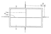
- the cross reference line 15 is displayed along the cross reference line 15a displayed along the short direction of the display device 10 and the longitudinal direction of the display device 10, as shown in FIG. And a cross reference line 15b.
- the cross reference line 15 is displayed when the display device 10 receives a user instruction to display the cross reference line 15 on the display unit 12 from a remote controller (not shown) that accepts a user instruction to the display device 10. May be displayed on the display unit 12.
- FIG. 2 is an overview diagram showing an outline of the bracket 20 provided in the latching system 1 according to the present embodiment.
- the bracket 20 includes a mounting hole 21, a laser light source (light source) 22, and a mounting detection switch (detection means) 23.
- the mounting hole 21 fixes the display device 10 to the bracket 20 by accepting insertion of a mounting portion included in the display device 10.
- the fixing (attachment) of the display device 10 to the bracket 20 will be described later.
- the laser light source 22 is a light source for irradiating a laser beam, and draws a laser beam reference line (reference line, second reference line) 25 to be referred to when the display device 10 is hooked on the wall surface. It is. Specifically, the laser light source 22 emits laser light when the bracket 20 is in the attachment mode (operation mode when attaching the display device 10 to the bracket 20), and draws the laser light reference line 25 on the wall surface. Further, in the present embodiment, one laser light source 22 is attached to each center of both end surfaces in the longitudinal direction of the bracket 20 and each center of both end surfaces in the short direction, as shown in FIG. Yes.
- the laser light reference line 25 is irradiated in the short direction of the bracket 20 as shown in FIG. 25a and a laser beam reference line 25b irradiated in the longitudinal direction.
- the attachment detection switch 23 is a switch that detects the completion of the attachment of the display device 10 to the bracket 20, and is provided in the vicinity of the attachment hole 21. Specifically, the attachment detection switch 23 is attached to the bracket 20 of the display device 10 when the attachment detection switch 23 is pressed by the attachment portion of the display device 10 inserted into the attachment hole 21. Detect that
- a method using laser light has been described as a method for presenting the reference line (that is, when the presenting means is configured to include the laser light source 22), but the present invention is not limited to this.
- the reference line may be presented using a vertically slidable bar and a horizontally slidable bar.
- a reference line (second reference line) may be presented using a string hanging vertically and a bar slidable horizontally.
- the reference line may be presented by exposing the rod and the string from the bracket 20 by sliding or hanging. Further, when the bracket 20 detects that the mounting of the display device 10 is completed by the mounting detection switch 23, the bracket 20 may be stored in the bracket 20 to stop presenting the reference line.
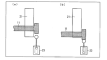
- FIG. 3 is a diagram illustrating an example of a positional relationship between the attachment portion 11 provided in the display device 10, the attachment hole 21 provided in the bracket 20, and the attachment detection switch 23 when the display device 10 is attached to the bracket 20.
- 3A shows the positional relationship between the mounting portion 11, the mounting hole 21, and the mounting detection switch 23 in a state immediately before the mounting portion 11 is inserted into the mounting hole 21 and the mounting is completed.
- B shows the positional relationship of the attachment portion 11, the attachment hole 21, and the attachment detection switch 23 in a state where the attachment is completed.
- FIGS. 4 and 5 each show an example of the positional relationship between the laser beam reference line 25 and a cross reference line (reference line, first reference line) 15 displayed on the display unit 12 included in the display device 10.
- FIG. 4 each show an example of the positional relationship between the laser beam reference line 25 and a cross reference line (reference line, first reference line) 15 displayed on the display unit 12 included in the display device 10.
- FIG. 4 each show an example of the positional relationship between the laser beam reference line 25 and a cross reference line (reference line, first reference line) 15 displayed on the display unit 12 included in the display device 10.
- the cross reference line 15 is displayed on the display unit 12 of the display device 10 and the laser light source 22 provided in the bracket 20 is irradiated with laser light.
- the laser beam reference line 25 is drawn on the wall surface (presentation process, irradiation process).
- the cross reference line 15 a displayed in the short direction of the display device 10 and the laser light reference line 25 a irradiated in the short direction of the bracket 20 are aligned. Not done (does not overlap in a straight line). Further, the cross reference line 15b displayed in the longitudinal direction of the display device 10 and the laser light reference line 25b irradiated in the longitudinal direction of the bracket 20 do not match.
- the user can easily recognize the positional relationship between the display device 10 and the bracket 20 by referring to the cross reference line 15 and the laser beam reference line 25 displayed on the display unit 12.
- the user moves the display device 10 so that the laser beam reference line 25 and the cross reference line 15 coincide with each other, thereby causing the display device 10 in the longitudinal direction and the short direction with respect to the bracket 20.
- the positional relationship (relative position) is adjusted (adjustment process). Thereby, alignment with the display apparatus 10 and the bracket 20 can be performed more correctly.
- the mounting portion 11 After the mounting portion 11 is inserted into the mounting hole 21, as shown in FIG. 3B, the mounting portion 11 provided in the display device 10 is in contact with the lower surface of the mounting hole 21 provided in the bracket 20.
- the attachment detection switch 23 When the position is moved, the attachment detection switch 23 is pressed, and it is detected that the attachment of the display device 10 to the bracket 20 is completed.
- the attachment detection switch 23 detects that the attachment of the display device 10 to the bracket 20 is completed, the irradiation of the laser light from the laser light source 22 is stopped, and the attachment mode in the bracket 20 ends. Thereby, the mounting operation of the display device 10 to the bracket 20 is completed.
- the case where the irradiation of the laser light from the laser light source 22 is stopped when the attachment of the display device 10 to the bracket 20 is completed has been described as an example, but the present invention is limited to this. Is not to be done.
- a configuration in which both the display of the cross reference line 15 on the display unit 12 and the irradiation of the laser light are stopped may be employed.
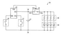
- FIG. 6 is a circuit diagram illustrating a configuration of the attachment detection circuit 30 provided in the bracket 20.
- the attachment detection circuit 30 provided in the bracket 20 is a circuit that controls ON / OFF of laser light irradiation from a laser diode group (LD) 34 that constitutes the laser light source 22 provided in the bracket 20. .
- LD laser diode group
- the attachment detection circuit 30 includes an attachment mode switch 31, an LD switch control unit 32, an LD switch 33, a laser diode group 34, a resistance group 35, an attachment detection interlocking switch 36, and a voltage power source 37. .
- the operation of the attachment detection circuit 30 will be described later.
- the first input terminal 32 a of the LD switch control unit 32 is connected to one end of the attachment mode switch 31, the second input terminal 32 b is connected to one end of the attachment detection interlocking switch 36, and the third input terminal 32 c is a terminal 38.
- the output terminal 32 d is connected to the control input terminal 33 a of the LD switch 33.
- the other end of the attachment mode switch 31 is connected to the terminal 39, and the other end of the attachment detection interlocking switch 36 is also connected to the terminal 39.
- the control input terminal 33 a of the LD switch 33 is connected to the output terminal 32 d of the LD switch control unit 32, the voltage input terminal 33 b is connected to the terminal 38, and the output terminal 33 c is connected to one end of the resistor group 35.
- the anode terminal of the laser diode group 34 is connected to the other end of the resistor group 35, and the cathode terminal is connected to the terminal 39.
- the positive terminal of the voltage power source 37 is connected to the terminal 38 and the negative terminal is connected to the terminal 39.
- the attachment mode switch 31 is a means for turning on the attachment mode in the bracket 20.
- the attachment mode switch 31 is a voltage supplied from the negative terminal of the voltage power supply 37 connected via the terminal 39 (hereinafter, also referred to as L level voltage) when the attachment mode switch 31 is pressed by the user. Is applied to the first input terminal 32 a of the LD switch control unit 32.
- the LD switch control unit 32 is a control means for switching the mounting mode on and off in the bracket 20.
- the LD switch control unit 32 When the L level voltage is applied to the first input terminal 32a, the LD switch control unit 32 outputs an ON control signal for turning on the LD switch 33 to the control input terminal 33a of the LD switch.
- the LD switch control unit 32 is driven by a voltage (hereinafter also referred to as an H level voltage) supplied from the positive terminal of the voltage power supply 37 connected to the third input terminal 32c via the terminal 38.
- the resistance group 35 is a means for controlling the value of the current flowing through the laser diode group 34. Specifically, the resistor group 35 supplies a current corresponding to the voltage drop in each resistor to the anode terminal of each laser diode in the laser diode group 34.
- the voltage drop in each resistor of the resistor group 35 is a value obtained by subtracting the forward drop voltage in each laser diode from the difference between the voltage value of the H level voltage and the voltage value of the L level voltage.
- the laser diode group 34 irradiates a laser beam with a light amount corresponding to the value of the current supplied from the resistor group 35. Thereby, the attachment mode in the bracket 20 is turned on. In addition, the user can recognize that the attachment mode in the bracket 20 has been turned on by irradiating the laser beam from the laser diode group 34.
- the attachment detection interlocking switch 36 is a means for interlocking with the attachment detection switch 23 provided in the bracket 20 and turning off the attachment mode in the bracket 20. Specifically, the attachment detection interlocking switch 36 is connected to the negative electrode of the voltage power source 37 connected via the terminal 39 in conjunction with the pressing of the attachment detection switch 23 when the attachment detection switch 23 is pressed. A voltage L level voltage supplied from the terminal is applied to the second input terminal 32 b of the LD switch control unit 32.
- the LD switch control unit 32 When the mounting mode of the bracket 20 is in the ON state, the LD switch control unit 32 outputs an OFF control signal for turning off the LD switch 33 when an L level voltage is applied to the second input terminal 32b. Output to the control input terminal 33a of the LD switch.
- the LD switch 33 stops applying voltage to one end of the resistor group 35 when the OFF control signal is input to the control input terminal 33a.
- the LD switch control unit 32 further detects that when the L mode voltage is applied to the first input terminal 32a when the mounting mode in the bracket 20 is ON, that is, the mounting mode switch 31 is pressed. At this time, an OFF control signal for turning off the LD switch 33 may be output to the control input terminal 33a of the LD switch.
- the user can also turn off the mounting mode in the bracket 20 even when the user wants to turn it off before completing the mounting operation.
- the bracket 20 may further have a configuration in which the laser light source 22 resumes the irradiation of the laser light again when the mounting detection switch 23 is pressed to a state where the mounting detection switch 23 is not pressed.
- the laser light source 22 included in the bracket 20 is irradiated with laser light for drawing the laser light reference line 25 when the attachment detection switch 23 detects that the display device 10 is not hooked. May be resumed.
- the cross reference line 15 is displayed on the display unit 12 and, as shown in FIG. 3B, the attachment unit 11 is attached so as to press the attachment detection switch 23.
- the bracket 20 emits laser light from the laser light source 22.
- the display device 10 causes the mounting detection switch 23 included in the bracket 20 to be pressed from a state in which the cross reference line 15 and the laser light reference line 25 coincide with each other, as shown in FIG. After the display device 10 is moved, the attachment is completed.
- the positional relationship between the cross reference line 15 and the laser light reference line 25 in a state where the mounting operation is completed is such that the cross reference line 15a and the laser light reference line 25a match, and the cross reference line 15b is The positional relationship is shifted downward from the laser beam reference line 25b.
- the display device 10 is lifted until the cross reference line 15b overlaps the laser light reference line 25b while maintaining the overlap between the cross reference line 15a and the laser light reference line 25a, the display device 10 is moved. It can be removed from the bracket 20.
- the bracket 20 can draw the laser beam reference line 25 again when the operation of removing the display device 10 that is hooked on the wall surface via the bracket 20 is performed. Accordingly, the user can perform the removal operation while confirming the positional relationship between the object and the bracket by referring to the laser beam reference line 25 in the operation of removing the display device 10 from the bracket 20.
- the display device 10 can be efficiently removed from the bracket 20 without extra effort such as lifting the display device 10 more than necessary. Thereby, the workability of the removal work from the bracket 20 of the display device 10 can be improved.
- the shape of the mounting hole 21 provided in the bracket 20 is not particularly limited.
- an L-shaped shape, an S-shaped shape, or the like is used as an example of the shape of the mounting hole. I can give you.
- the L-shaped shape is, for example, a shape in which the display device is fixed to the bracket by moving the attachment portion of the display device inserted into the attachment hole in the short direction of the display device and then moving it further in the longitudinal direction. It is.
- the display device displays the display by moving the cross line displayed on the display device so that the user indicates the direction in which the display device should be moved next. You may improve workability
- the display device displays a display different from the cross line, which indicates the direction in which the user should move the display device next, by superimposing the cross line on the display, thereby improving the workability of attaching the display device to the bracket. May be improved.
- the display device 10 may employ a configuration in which the display device 10 includes a camera that captures an image of the laser light reference line 25 presented on the wall surface. And the display apparatus 10 may display the cross reference line 15 based on the laser beam reference line 25 imaged with the camera.
- the user refers to the laser beam reference line 25 when the display device 10 is hooked on the wall surface, and moves the display device 10 so that the cross reference line 15 matches the laser beam reference line 25.
- the display device 10 can be more easily hooked on the wall surface.
- the camera can be used for Skype (registered trademark), for example.
- the display device 10 does not have a built-in camera, the display device 10 includes a holder for installing a camera, a mobile phone, a smartphone, or the like (also referred to as an external camera) on the back surface of the display device 10.
- a camera a mobile phone, a smartphone, or the like
- an external camera also referred to as an external camera
- Examples of the display device 10 according to the present embodiment include a television receiver, an electronic blackboard, and an electronic signboard (digital signage).
- the electronic blackboard may be, for example, a so-called whiteboard provided with an image scanner and a printer, or a display integrated with a touch panel, which can perform a touch operation with a touch pen, a finger, or the like. It may be a so-called touch panel type interactive whiteboard provided as a unit. Further, when the electronic blackboard is an interactive whiteboard, the electronic blackboard may or may not be able to display a television broadcast on the display unit.
- the above-described cross reference line is a sheet on which characters, figures, and the like are written using a pen or the like. It may be drawn, or may be stamped on a frame arranged so as to surround the periphery of the display unit.
- a bracket according to an aspect of the present invention is a bracket for hanging an object on a wall surface, and includes a presentation unit that presents a reference line that is referred to when the object is hooked on the wall surface. It is characterized by that.
- the bracket presents a reference line that is referred to when the object is hooked on the wall surface by the presenting means.
- the user can easily adjust the positional relationship between the object and the bracket by referring to the reference line when the object is hooked on the wall surface.
- the bracket can improve workability when the object is hooked on the wall surface.
- the presenting means includes a light source that draws a reference line on the wall surface that is referred to when the object is hooked on the wall surface by irradiating the wall surface with light. It is preferable.
- the bracket draws a reference line on the wall surface that is referred to when the object is hooked on the wall surface by light (for example, laser light) emitted from the light source. Therefore, the user can easily adjust the positional relationship between the object and the bracket by referring to the reference line when the object is hooked on the wall surface. Thereby, the bracket can improve workability when the object is hooked on the wall surface.
- light for example, laser light
- the bracket according to one aspect of the present invention further includes detection means for detecting that the object is hooked on the wall surface, and the light source detects that the object is hooked on the wall surface. It is preferable to stop the light irradiation for drawing the reference line, triggered by the detection by the means.
- the bracket stops the irradiation of the light from the light source when the detection unit detects that the object is hooked on the wall surface. Therefore, the user can easily recognize that the object is hooked on the wall surface by confirming that the irradiation of light from the light source is stopped.
- the light source is a light source for drawing the reference line when the detection unit detects that the object is no longer caught on the wall surface. It is preferable to resume the irradiation.
- the bracket can redraw the reference line on the wall surface when an operation of removing an object that is hooked on the wall surface is performed. Accordingly, the user can perform the removal work while confirming the positional relationship between the object and the bracket by referring to the reference line in the work of removing the object from the wall surface. Therefore, the bracket can improve the workability in the work of removing the object.
- the object is a display device, and a reference line drawn on the wall surface by light emitted from the light source is used when the display device is hooked on the wall surface. It is preferable to match the reference line displayed on the display device.
- the user when the user hangs the object on the wall surface, the user only needs to match the reference line displayed on the display device with the reference line drawn on the wall surface. Thereby, the user can adjust the positional relationship between the object and the bracket more easily.
- the reference line drawn on the wall surface by the light emitted from the light source and the reference line displayed on the display device are both cross lines. preferable.
- the cross line displayed on the display device may coincide with the cross line drawn on the wall surface. Therefore, the user can adjust the positional relationship between the object and the bracket more accurately.
- a latching system is a latching system including a display device and a bracket for latching the display device on a wall surface, and the bracket presents a second reference line.
- the display device is characterized by displaying a first reference line for matching with the second reference line when the display device is hooked on the wall surface.
- the bracket presents the second reference line that is referred to when the display device is latched on the wall surface, and the display device includes the second reference line.
- a first reference line for matching with the reference line is displayed.
- the user refers to the second reference line when the object is hooked on the wall surface, and moves the display device so that the first reference line matches the second reference line.
- the positional relationship between the object and the bracket can be easily adjusted. Therefore, the user can hook the display device on the wall surface more easily.
- the said latching system can improve workability
- the bracket has a second reference line that is referred to when the display device is hooked on the wall surface by the light emitted from the light source.
- Drawing and the display device displays a first reference line for matching with the second reference line.
- the user refers to the second reference line when the object is hooked on the wall surface, and moves the display device so that the first reference line matches the second reference line.
- the positional relationship between the object and the bracket can be easily adjusted. Therefore, the user can hook the display device on the wall surface more easily.
- the said latching system can improve workability
- a latching system in which the display device is a television receiver or an electronic blackboard is also included in the scope of the present invention.
- a television receiver refers to a device having a function of displaying a broadcast image, and has a function of receiving the image and a function of receiving the image. Including both with no device.
- the monitor corresponds to a television receiver.
- “broadcasting” is not limited to wireless broadcasting such as terrestrial digital broadcasting, but also includes wired broadcasting such as cable television and IPTV (Internet Protocol Television).
- the latching method is a latching method for latching an object on a wall surface using a bracket, and presents a reference line that is referred to when the object is latched on the wall surface. And a adjusting step of adjusting the relative position of the object with respect to the bracket by referring to the reference line.
- the latching method adjusts the relative position of the object with respect to the bracket in the adjustment step by referring to the reference line presented in the presentation step.
- the user can easily adjust the positional relationship between the object and the bracket by referring to the reference line when the object is hooked on the wall surface. Therefore, the user can easily hang the object on the wall surface using the bracket.
- the said latching method can improve the workability
- the latching method is a latching method of latching an object on a wall surface using a bracket, and the reference line is obtained by irradiating the wall surface with light from a light source provided in the bracket.
- the method includes an irradiation step of drawing on the wall surface, and an adjustment step of adjusting a relative position of the object with respect to the bracket by referring to the reference line.
- the latching method adjusts the relative position of the object with respect to the bracket in the adjustment step by referring to a reference line drawn on the wall surface in the irradiation step.
- the user can easily adjust the positional relationship between the object and the bracket by referring to the reference line when the object is hooked on the wall surface. Therefore, the user can easily hang the object on the wall surface using the bracket.
- the said latching method can improve the workability
- the display device is a display device that can be hooked on a wall surface, and displays a first reference line that is referred to when the display device is hooked on the wall surface. It is characterized by.
- the display device presents a first reference line that is referred to when the display device is hooked on the wall surface.
- the user can easily adjust the positional relationship between the display device and the wall surface by referring to the first reference line when the display device is hooked on the wall surface.
- the said display apparatus can improve workability
- the display device includes a connection unit for connecting an external tuner, and displays the first reference line only when the external tuner is not connected to the connection unit. Is preferable.
- the display device is the above only when the external tuner is not connected, that is, when the display device is not hooked on the wall surface or when the display device is removed from the wall surface.
- a first reference line is displayed. Further, when the external tuner is connected, that is, when it is not suitable for being hooked on the wall surface or being detached from the wall surface, the first reference line is not displayed.
- the user can easily recognize whether or not the display device is in a state suitable for being hooked on or removed from the wall surface, depending on whether or not the first reference line is displayed. can do.
- the display device captures the second reference line that is referred to when the display device is hooked on the wall surface and is presented on the wall surface. It is preferable to display the first reference line based on the second reference line imaged by the camera.
- the display device displays the first reference line based on the second reference line presented on the wall surface. Accordingly, the user refers to the second reference line when the display device is hooked on the wall surface, and moves the display device so that the first reference line matches the second reference line. By doing so, the display device can be more easily hooked onto the wall surface.
- the display device can display a first reference line suitable for the second reference line, regardless of what the second reference line is. Therefore, the display device can improve workability when the display device is hooked on the wall surface.
- the display device according to the present invention can be suitably applied to a television receiver, an electronic blackboard, an electronic signboard, and the like.
- the bracket according to the present invention can be suitably used as a device for fixing a television receiver, an electronic blackboard, an electronic signboard, and the like to a wall or the like.
- Display device object, television receiver, electronic blackboard
- Mounting portion 12
- Display portion 15
- Cross reference line reference line, first reference line
- Mounting hole 22
- Laser light source light source, presentation means
- Mounting detection switch detection means
- Laser beam reference line reference line, second reference line
- mounting detection circuit 31
- mounting mode switch 32
- LD switch control unit 33
- LD switch 34
- laser diode group 35
- resistor group 36
- mounting detection interlocking switch 37 voltage power supply 38, 39 terminal
Landscapes
- Engineering & Computer Science (AREA)
- General Engineering & Computer Science (AREA)
- Mechanical Engineering (AREA)
- Devices For Indicating Variable Information By Combining Individual Elements (AREA)
Abstract
本発明の一態様に係るブラケット(20)は、表示装置(10)を壁面に掛止するためのブラケット(20)であって、表示装置(10)を該壁面に掛止する際に参照される基準線を提示するレーザ光源(22)を備えている。
Description
本発明は、物体を壁面に掛止するためのブラケット、ブラケットを利用した掛止システム、ブラケットを利用した掛止方法、及び、壁面に掛止可能な表示装置に関するものである。
近年、スマートフォン及び携帯電話などに代表される携帯端末との連携機能を搭載したテレビジョン受像機(以降、単にテレビとも呼称する)が普及してきている。このような携帯端末は、例えば、Wi-Fi(登録商標)などを利用した無線通信によってテレビを操作したり、テレビに表示される画像を携帯端末に表示したりすることができる。
また、近年、テレビの薄型化、及び軽量化が進んできていることに伴い、テレビの持ち運びなどが比較的容易になってきている。これによって、ユーザは、テレビのレイアウトをより自由に決めることができるようになってきている。
今後、このようなレイアウトに自由度のあるテレビ(いわゆる、レイアウト・フリーテレビ)は、該テレビを頻繁に壁面などに掛止したり、取り外したりして使用する事が予測される。
しかしながら、このような薄型のテレビであっても、壁へ取り付ける際には、壁側の金具とテレビの金具とを正しく嵌合させる作業が必要となる。この作業は、テレビの裏側を覗き込んで金具の位置関係を確かめながら行う必要があるため、容易には行うことができない。また、テレビが大型である場合や重い場合などには、テレビの裏面を覗き込むことはますます困難となる。
このように、テレビの壁への取り付け作業時には、ユーザに大きな負担を強いることになる。また、金具が正しく嵌合していない場合、取り付けが終わったと思ったユーザがテレビを持つ力を緩めた際にテレビが落下してしまい、テレビが破損したりする可能性がある。
例えば、特許文献1には、撮像された十字形部及び四角形部よりなるアライメントマークを含む画像を拡大してモニタ上に表示し、表示されたアライメントマークと予め記憶されている基準パターンとの位置合わせを行うことで、検出位置の設定精度を向上させる画像処理装置が開示されている。
しかしながら、特許文献1に記載の画像処理装置は、TFT液晶パネルのパターン寸法検査を行うのに適した画像処理装置を提供するために、顕微鏡と組み合わされたカメラによって撮像された微細なアライメントマークを拡大してモニタ画面上に表示する技術である。また、これによって、TFT液晶パネルが搭載されたステージの移動制御を向上する事を目的としている。したがって、特許文献1に記載の画像処理装置では、該画像処理装置を壁面に掛止する場合に、何らその掛止作業の作業性を向上させることはできない。
本発明は、上記の課題を解決するためになされたものであり、その主たる目的は、物体を壁面に掛止する際の作業性を向上させることができるブラケットおよび掛止方法を提供することにある。
本発明の一態様に係るブラケットは、上記の課題を解決するために、物体を壁面に掛止するためのブラケットであって、上記物体を上記壁面に掛止する際に参照される基準線を提示する提示手段を備えている、ことを特徴としている。
本発明の一態様に係る掛止システムは、上記の課題を解決するために、表示装置と、該表示装置を壁面に掛止するためのブラケットと、を備える掛止システムであって、上記ブラケットは、第2の基準線を提示する提示手段を備え、上記表示装置は、上記第2の基準線と合致させるための第1の基準線を、該表示装置を上記壁面に掛止する際に表示する、ことを特徴としている。
また、本発明の一態様に係る掛止方法は、上記の課題を解決するために、ブラケットを用いて物体を壁面に掛止する掛止方法であって、上記物体を上記壁面に掛止する際に参照される基準線を提示する提示工程と、上記基準線を参照することによって、上記ブラケットに対する上記物体の相対位置を調整する調整工程と、を含んでいる、ことを特徴としている。
また、本発明の一態様に係る表示装置は、壁面に掛止可能な表示装置であって、当該表示装置を上記壁面に掛止する際に参照される第1の基準線を表示する、ことを特徴としている。
本発明の一態様によれば、ユーザは、上記物体を上記壁面に掛止する際に、上記光源から照射された光によって該壁面に描かれる基準線を参照することによって、上記物体と上記ブラケットとの位置関係を、容易に調整することができる。
本発明の一実施形態に係る掛止システムであって、物体を例えば壁面などに掛止するための掛止システムについて、図1から図6を参照して説明する。なお、本実施形態では、物体が表示装置である場合を例に挙げて説明するが、本発明はこれに限定されるものではない。但し、この実施形態に記載されている構成は、特に特定的な記載がない限り、この発明の範囲をそれのみに限定する趣旨ではなく、単なる説明例に過ぎない。
〔掛止システム〕
まず、本実施形態に係る掛止システムについて、図1を参照して説明する。図1は、本実施形態に係る掛止システム1の構成の概略を示す図である。
まず、本実施形態に係る掛止システムについて、図1を参照して説明する。図1は、本実施形態に係る掛止システム1の構成の概略を示す図である。
図1に示すように、掛止システム1は、表示装置(物体)10、及びブラケット20を備えている。また、ブラケット20には、表示装置10の備える取付部(不図示)を差し込むための取付穴21を備えている。
(表示装置)
表示装置10は、図1に示すように、表示部12を備えている。また、表示装置10の備える表示部12には、表示装置10の中心に交点を有する十字基準線15が表示されている。
表示装置10は、図1に示すように、表示部12を備えている。また、表示装置10の備える表示部12には、表示装置10の中心に交点を有する十字基準線15が表示されている。
本実施形態においては、十字基準線15は、図1に示すように、表示装置10の短手方向に沿って表示された十字基準線15aと、表示装置10の長手方向に沿って表示された十字基準線15bとを含んでいる。
なお、十字基準線15は、例えば、表示装置10が、当該表示装置10に対するユーザ指示を受け付けるリモコン(不図示)から表示部12に十字基準線15を表示する旨のユーザ指示を受信した場合に、表示部12に表示されればよい。
また、本実施形態に係る表示装置10は、外部から供給されるコンテンツを取得(受信)するための外部チューナを接続するためのチューナ接続部(不図示)を備えていている構成を採用してもよい。このような場合には、表示装置10は、チューナ接続部に外部チューナが接続されていない場合に限り、十字基準線15を表示してもよい。
(ブラケット)
次に、ブラケット20について、図2を参照して説明する。図2は、本実施形態に係る掛止システム1の備えるブラケット20の概略を示す概観図である。
次に、ブラケット20について、図2を参照して説明する。図2は、本実施形態に係る掛止システム1の備えるブラケット20の概略を示す概観図である。
図2に示すように、ブラケット20は、取付穴21、レーザ光源(光源)22、及び、取付検出スイッチ(検出手段)23を備えている。
取付穴21は、表示装置10の備える取付部の挿入を受け付けることによって、表示装置10をブラケット20に固定する。なお、表示装置10のブラケット20への固定(取り付け)については、後述する。
レーザ光源22は、レーザ光を照射するための光源であり、表示装置10を壁面に掛止する際に参照されるレーザ光基準線(基準線、第2の基準線)25を壁面に描く光源である。具体的には、レーザ光源22は、ブラケット20が取付モード(表示装置10をブラケット20に取り付ける際の動作モード)である場合においてレーザ光を照射し、壁面にレーザ光基準線25を描く。また、レーザ光源22は、本実施形態においては、図2に示すように、ブラケット20の長手方向の両端面の各中央、及び短手方向の両端面の各中央にそれぞれ1つずつ取り付けられている。
本実施形態では、レーザ光源22が上述のようにブラケット20に取り付けられているため、レーザ光基準線25は、図1に示すように、ブラケット20の短手方向に照射されるレーザ光基準線25aと、長手方向に照射されるレーザ光基準線25bとを含むことになる。
なお、本実施形態では、壁面にレーザ光基準線25を描く光の光源がレーザ光源22である場合を例に挙げて説明するが、本発明はこれに限定されるものではなく、例えば、スリット光などであってもよい。
取付検出スイッチ23は、表示装置10のブラケット20への取り付けが完了したことを検出するスイッチであって、取付穴21の近傍に設けられている。具体的には、取付検出スイッチ23は、取付穴21に挿入された表示装置10の備える取付部によって、当該取付検出スイッチ23が押下された場合に、表示装置10のブラケット20への取り付けが完了したことを検出する。
また、ブラケット20は、取付検出スイッチ23によって表示装置10の取り付けが完了したことが検出されたことを契機とし、レーザ光源22によるレーザ光の照射を停止するよう動作する。
さらに、ブラケット20は、当該ブラケット20の備える各部へ電圧を供給する電圧電源(不図示)を備えている。なお、電圧電源としては、例えば、内蔵された電池などを挙げることができる。
なお、本実施形態では、基準線を提示する方法として、レーザ光を用いる方法(つまり、レーザ光源22を含んで提示手段が構成されている場合)について説明を行ったが本発明はこれに限定されない。例えば、垂直方向にスライド可能な棒、及び、水平方向にスライド可能な棒を用いて、基準線を提示してもよい。また、垂直方向に垂らす紐、及び、水平方向にスライド可能な棒を用いて、基準線(第2の基準線)を提示してもよい。
この場合には、ブラケット20は、取付モードである場合に、棒および紐を、スライド又は垂らすことで当該ブラケット20から露出させることによって、基準線を提示すればよい。また、ブラケット20は、取付検出スイッチ23によって表示装置10の取り付けが完了したことが検出された場合に、棒および紐を当該ブラケット20に格納することによって、基準線の提示を停止すればよい。
〔取付完了の検出〕
次に、取付検出スイッチ23による、表示装置10のブラケット20への取り付け完了の検出について、図3を参照して説明する。図3は、表示装置10のブラケット20への取り付け時における、表示装置10の備える取付部11と、ブラケット20の備える取付穴21及び取付検出スイッチ23との位置関係の一例を示す図である。図3の(a)は、取付部11が取付穴21に挿入され、かつ、取り付けが完了する直前の状態における取付部11、取付穴21、及び取付検出スイッチ23の位置関係を示し、図3の(b)は、取り付けが完了した状態における取付部11、取付穴21、及び取付検出スイッチ23の位置関係を示している。
次に、取付検出スイッチ23による、表示装置10のブラケット20への取り付け完了の検出について、図3を参照して説明する。図3は、表示装置10のブラケット20への取り付け時における、表示装置10の備える取付部11と、ブラケット20の備える取付穴21及び取付検出スイッチ23との位置関係の一例を示す図である。図3の(a)は、取付部11が取付穴21に挿入され、かつ、取り付けが完了する直前の状態における取付部11、取付穴21、及び取付検出スイッチ23の位置関係を示し、図3の(b)は、取り付けが完了した状態における取付部11、取付穴21、及び取付検出スイッチ23の位置関係を示している。
表示装置10のブラケット20への取り付けが完了する直前の状態では、図3の(a)に示すように、取付部11は、取付穴21に挿入されているものの、取付検出スイッチ23を押下していない。
この状態から、取付部11が取付穴21の下面に接するように表示装置10の位置を移動させると、つまり、表示装置10を位置をブラケット20への取り付けが完了する位置に移動させると、図3の(b)に示すように、取付部11の一端が取付検出スイッチ23を押下することになる。
取付検出スイッチ23は、押下されたことを検出することによって、表示装置10のブラケット20への取り付けが完了したことを検出する。
〔取付作業の流れ〕
次に、表示装置10のブラケット20への取り付けを行う取付作業の流れについて、図4及び図5を参照して説明する。図4及び図5は、それぞれ、レーザ光基準線25と、表示装置10の備える表示部12に表示される十字基準線(基準線、第1の基準線)15との位置関係の一例を示す図である。
次に、表示装置10のブラケット20への取り付けを行う取付作業の流れについて、図4及び図5を参照して説明する。図4及び図5は、それぞれ、レーザ光基準線25と、表示装置10の備える表示部12に表示される十字基準線(基準線、第1の基準線)15との位置関係の一例を示す図である。
まず、表示装置10のブラケット20への取付作業を開始する際に、表示装置10の表示部12に十字基準線15を表示させると共に、ブラケット20の備えるレーザ光源22からレーザ光を照射させることにより、壁面にレーザ光基準線25を描かせる(提示工程、照射工程)。
取付作業を開始した直後は、図4に示すように、表示装置10の短手方向に表示された十字基準線15aと、ブラケット20の短手方向に照射されたレーザ光基準線25aとが合致していない(一直線に重なっていない)。また、表示装置10の長手方向に表示された十字基準線15bと、ブラケット20の長手方向に照射されたレーザ光基準線25bとが合致していない。
図4に示すように、レーザ光基準線25aと十字基準線15aとが合致していない場合、ユーザは、表示装置10とブラケット20との短手方向の位置合わせができていないことを、表示装置10の裏側を覗かなくとも視覚的に認識することができる。また、レーザ光基準線25bと十字基準線15bとが合致していない場合、ユーザは、表示装置10とブラケット20との長手方向の位置合わせができていないことを、表示装置10の裏側を覗かなくとも視覚的に認識することができる。
つまり、ユーザは、表示部12に表示された十字基準線15と、レーザ光基準線25とを参照することによって、表示装置10とブラケット20との位置関係を容易に認識することができる。
また、ユーザは、図5に示すように、レーザ光基準線25と十字基準線15とが合致するように表示装置10を動かすことによって、ブラケット20に対する表示装置10の長手方向及び短手方向の位置関係(相対位置)を調整する(調整工程)。これによって、表示装置10とブラケット20との位置合わせをより正確に行うことができる。
表示装置10とブラケット20との長手方向及び短手方向の位置合わせを行った後は、ユーザは、表示装置10を、ブラケット20に対する長手方向及び短手方向の位置関係を維持したまま近づけ、ブラケット20に重ね合わせればよい。表示装置10をブラケット20に重ね合わせることにより、表示装置10の備える取付部11は、図3の(a)に示すように、ブラケット20の備える取付穴21に挿入される。
取付部11が取付穴21に挿入された後、図3の(b)に示すように、表示装置10の備える取付部11がブラケット20の備える取付穴21の下面に接するように表示装置10の位置を移動させると、取付検出スイッチ23が押下され、表示装置10のブラケット20への取り付けが完了したことが検出される。
取付検出スイッチ23によって表示装置10のブラケット20への取り付けが完了したことが検出されると、レーザ光源22からのレーザ光の照射が停止され、ブラケット20における取付モードが終了する。これによって、表示装置10のブラケット20への取付作業が終了する。
上述の構成のように、表示装置10のブラケット20への取り付けが完了した場合に、取付検出スイッチ23によってレーザ光源22からのレーザ光の照射が停止されることによって、ユーザは、表示装置10のブラケット20への取り付けが完了したことを容易に認識することができる。これによって、本実施形態に係る掛止システム1は、表示装置10のブラケット20への取付作業の作業性を向上させることができる。
なお、本実施形態では、表示装置10のブラケット20への取り付けが完了した場合にレーザ光源22からのレーザ光の照射が停止される場合を例に挙げて説明したが、本発明はこれに限定されるものではない。例えば、十字基準線15の表示部12への表示、及びレーザ光の照射の双方が停止される構成を採用してもよい。
さらに、本実施形態に係る表示装置10は、ブラケット20への取り付けが完了した場合に、表示装置10の備えるスピーカ(不図示)から、ブラケット20への取り付けが完了した旨を表す音声(例えば、音楽及びアナウンスなど)を出力する構成を採用してもよい。
〔取付検出回路〕
次に、本実施形態におけるブラケット20の備える、取付検出回路30について、図6を参照して説明する。図6は、ブラケット20の備える取付検出回路30の構成を示す回路図である。
次に、本実施形態におけるブラケット20の備える、取付検出回路30について、図6を参照して説明する。図6は、ブラケット20の備える取付検出回路30の構成を示す回路図である。
ブラケット20の備える取付検出回路30は、図6に示すように、ブラケット20の備えるレーザ光源22を構成するレーザダイオード群(LD)34からのレーザ光の照射のON/OFFを制御する回路である。
図6に示すように、取付検出回路30は、取付モードスイッチ31、LDスイッチ制御部32、LDスイッチ33、レーザダイオード群34、抵抗群35、取付検出連動スイッチ36、電圧電源37を備えている。なお、取付検出回路30の動作については、後述する。
(取付検出回路の回路構成)
LDスイッチ制御部32の第1の入力端子32aは取付モードスイッチ31の一端に接続され、第2の入力端子32bは取付検出連動スイッチ36の一端に接続され、第3の入力端子32cは端子38に接続され、出力端子32dは、LDスイッチ33の制御入力端子33aに接続されている。また、取付モードスイッチ31の他の一端は端子39に接続されており、取付検出連動スイッチ36の他の一端もまた端子39に接続されている。
LDスイッチ制御部32の第1の入力端子32aは取付モードスイッチ31の一端に接続され、第2の入力端子32bは取付検出連動スイッチ36の一端に接続され、第3の入力端子32cは端子38に接続され、出力端子32dは、LDスイッチ33の制御入力端子33aに接続されている。また、取付モードスイッチ31の他の一端は端子39に接続されており、取付検出連動スイッチ36の他の一端もまた端子39に接続されている。
LDスイッチ33の制御入力端子33aはLDスイッチ制御部32の出力端子32dに接続され、電圧入力端子33bは端子38に接続され、出力端子33cは抵抗群35の一端に接続されている。
また、レーザダイオード群34のアノード端子は抵抗群35の他の一端に接続され、カソード端子は端子39に接続されている。
電圧電源37の正極端子は端子38に接続され、負極端子は端子39に接続されている。
(取付検出回路の動作)
次に、取付検出回路30の動作について説明する。
次に、取付検出回路30の動作について説明する。
取付モードスイッチ31は、ブラケット20における取付モードをONにするための手段である。具体的には、取付モードスイッチ31は、当該取付モードスイッチ31がユーザによって押下されると、端子39を介して接続された電圧電源37の負極端子から供給される電圧(以降、Lレベル電圧とも呼称する)を、LDスイッチ制御部32の第1の入力端子32aに印加する。
LDスイッチ制御部32は、ブラケット20における取付モードのONとOFFとを切り替えるための制御手段である。LDスイッチ制御部32は、第1の入力端子32aにLレベル電圧が印加されると、LDスイッチ33をON状態にするためのON制御信号をLDスイッチの制御入力端子33aに出力する。なお、LDスイッチ制御部32は、端子38を介して第3の入力端子32cに接続された電圧電源37の正極端子から供給される電圧(以降、Hレベル電圧とも呼称する)によって駆動する。
LDスイッチ33は、レーザダイオード群34の発光と非発光とを切り替えるための手段である。LDスイッチ33は、ON制御信号が制御入力端子33aに入力されると、端子38を介して電圧電源37の正極端子から供給されるHレベルを、抵抗群35の一端に印加する。
抵抗群35は、レーザダイオード群34に流れる電流の値を制御するための手段である。具体的には、抵抗群35は、各抵抗における電圧降下に応じた電流をレーザダイオード群34の各レーザダイオードのアノード端子に供給する。なお、抵抗群35の各抵抗における電圧降下は、Hレベル電圧の電圧値とLレベル電圧の電圧値との差から各レーザダイオードにおける順方向降下電圧を引いた値となる。抵抗群35の各抵抗の抵抗値を変えることによって、レーザダイオード群34の各レーザダイオードに供給する電流値を変えることができる。
レーザダイオード群34は、抵抗群35から供給された電流の値に応じた光量のレーザ光を照射する。これによって、ブラケット20における取付モードがON状態となる。なお、ユーザは、レーザダイオード群34からレーザ光が照射されることにより、ブラケット20における取付モードがON状態になったことを認識することができる。
取付検出連動スイッチ36は、ブラケット20の備える取付検出スイッチ23に連動し、ブラケット20における取付モードをOFFにするための手段である。具体的には、取付検出連動スイッチ36は、取付検出スイッチ23が押下されると、当該取付検出スイッチ23が押下されたことに連動して、端子39を介して接続された電圧電源37の負極端子から供給される電圧Lレベル電圧を、LDスイッチ制御部32の第2の入力端子32bに印加する。
LDスイッチ制御部32は、ブラケット20における取付モードがON状態である場合に、第2の入力端子32bにLレベル電圧が印加されると、LDスイッチ33をOFF状態にするためのOFF制御信号をLDスイッチの制御入力端子33aに出力する。LDスイッチ33は、OFF制御信号が制御入力端子33aに入力されると、抵抗群35の一端への電圧の印加を停止する。
これによって、抵抗群35に電流が流れなくなり、レーザダイオード群34にも電流が供給されなくなる。したがって、レーザダイオード群からのレーザ光の照射が停止され、ブラケット20における取付モードがOFF状態となる。なお、ユーザは、レーザダイオード群34からのレーザ光の照射が停止されることにより、ブラケット20における取付モードがOFF状態になったことを認識することができる。
なお、LDスイッチ制御部32は、さらに、ブラケット20における取付モードがON状態である場合に、第1の入力端子32aにLレベル電圧が印加されたとき、すなわち、取付モードスイッチ31が押下されたとき、LDスイッチ33をOFF状態にするためのOFF制御信号をLDスイッチの制御入力端子33aに出力してもよい。
この構成によれば、ユーザは、ブラケット20における取付モードを、取付作業が完了する前にOFFにしたい場合にも、OFFにすることができる。
なお、本実施形態では、表示装置10の表示部12に表示される十字基準線15、及び、レーザ光基準線25が十字である場合を例に挙げて説明したが、本発明はこれに限定されるものではない。
〔取外し作業〕
なお、ブラケット20は、取付検出スイッチ23が押下されている状態から、押下されない状態に遷移した場合に、再びレーザ光源22によるレーザ光の照射を再開する構成を、さらに有していても良い。換言すれば、ブラケット20の備えるレーザ光源22は、表示装置10が掛止されなくなったことが取付検出スイッチ23によって検出されたことを契機として、レーザ光基準線25を描くためのレーザ光の照射を再開してもよい。
なお、ブラケット20は、取付検出スイッチ23が押下されている状態から、押下されない状態に遷移した場合に、再びレーザ光源22によるレーザ光の照射を再開する構成を、さらに有していても良い。換言すれば、ブラケット20の備えるレーザ光源22は、表示装置10が掛止されなくなったことが取付検出スイッチ23によって検出されたことを契機として、レーザ光基準線25を描くためのレーザ光の照射を再開してもよい。
このような構成をさらに有するブラケット20を備える掛止システム1における、ブラケット20に取り付けられている表示装置10を当該ブラケット20から取り外す、取外し作業について以下に説明する。
まず、表示部12に十字基準線15を表示させると共に、図3の(b)に示すように、取付部11が取付検出スイッチ23を押下するように取り付けられている状態から、図3の(a)に示すように、取付検出スイッチ23が押下されない状態まで、ユーザが表示装置10を持ち上げると、ブラケット20は、レーザ光源22からレーザ光を照射する。
なお、表示装置10は、上述の取付作業において、図5に示すように、十字基準線15とレーザ光基準線25とが合致した状態から、ブラケット20の備える取付検出スイッチ23が押下されるように表示装置10を移動させたうえで取り付けを完了している。つまり、取付作業が完了した状態での、十字基準線15とレーザ光基準線25との位置関係は、十字基準線15a及びレーザ光基準線25aが合致しており、かつ、十字基準線15bがレーザ光基準線25bよりも下方にずれた位置関係になっている。
したがって、取外し作業においては、十字基準線15aとレーザ光基準線25aとの重なりを維持したまま、十字基準線15bがレーザ光基準線25bと重なるまで表示装置10を持ち上げれば、表示装置10をブラケット20から取り外すことができる。
この構成によれば、ブラケット20は、当該ブラケット20を介して壁面に掛止されている表示装置10の取外し作業が行われる場合に、レーザ光基準線25を再び描くことができる。これによって、ユーザは、表示装置10をブラケット20から取り外す作業において、レーザ光基準線25を参照することによって上記物体と上記ブラケットとの位置関係を確認しつつ、取外し作業を行うことができるため、必要以上に表示装置10を持ち上げてしまうなどといった、余計な労力をかけることなく、表示装置10をブラケット20から効率よく取り外すことができる。これによって、表示装置10のブラケット20からの取外し作業の作業性を向上させることができる。
なお、本発明においては、ブラケット20の備える取付穴21の形状は特に限定されるものではないが、例えば、取付穴の形状の一例として、L字型の形状、及びS字型の形状などをあげることができる。
L字型の形状とは、例えば、取付穴に挿入された表示装置の有する取付部を表示装置の短手方向に下ろした後、さらに長手方向に移動させることによって表示装置をブラケットに固定させる形状である。
また、取付穴がこのような形状を有している場合、表示装置は、表示装置に表示される十字線を、ユーザが表示装置を次に移動させるべき方向を示すように動かすことによって、表示装置のブラケットへの取付作業の作業性を向上させてもよい。また、表示装置は、ユーザが表示装置を次に移動させるべき方向を示す、十字線とは異なる表示を、十字線に重畳して表示することによって、表示装置のブラケットへの取付作業の作業性を向上させてもよい。
〔変形例〕
なお、本実施形態における表示装置10は、当該表示装置10を当該壁面に提示されるレーザ光基準線25を撮像するカメラを備えている構成を採用してもよい。そして、表示装置10は、カメラによって撮像されたレーザ光基準線25に基づいて十字基準線15を表示してもよい。
なお、本実施形態における表示装置10は、当該表示装置10を当該壁面に提示されるレーザ光基準線25を撮像するカメラを備えている構成を採用してもよい。そして、表示装置10は、カメラによって撮像されたレーザ光基準線25に基づいて十字基準線15を表示してもよい。
これによって、ユーザは、表示装置10を壁面に掛止する際にレーザ光基準線25を参照し、十字基準線15がレーザ光基準線25と合致するように表示装置10を移動させることによって、表示装置10をより容易に上記壁面に掛止することができる。
上記カメラは、例えばSkype(登録商標)等に利用可能である。また、表示装置10がカメラを内蔵していない場合には、カメラ、携帯電話及びスマートフォンなど(外付けカメラとも記載する)を表示装置10の裏面に設置するためのホルダーを備え、外付けカメラから送信される画像信号を表示装置10で受信することにより、カメラが内蔵されている場合と同様の構成を実現することができる。
〔付記事項〕
本実施形態に係る表示装置10としては、例えば、テレビジョン受像機、電子黒板、及び、電子看板(デジタルサイネージ)などを例に挙げることができる。
本実施形態に係る表示装置10としては、例えば、テレビジョン受像機、電子黒板、及び、電子看板(デジタルサイネージ)などを例に挙げることができる。
なお、電子黒板は、例えば、イメージスキャナ及びプリンタを備えた、いわゆるホワイトボードであってもよいし、タッチパネル一体型のディスプレイであって、タッチペン及び指などによってタッチ操作を行うことのできるディスプレイを表示部として備えた、いわゆるタッチパネルタイプのインタラクティブ・ホワイトボードであってもよい。さらに、電子黒板がインタラクティブ・ホワイトボードである場合、電子黒板は、表示部にテレビ放送が表示できるものであってもよく、表示できないものであってもよい。
また、本実施形態に係る電子黒板がホワイトボードである場合、上述した十字基準線は、ペンなどを用いて文字や図形などを書き込むシートであって、表示部を構成するシートの一部に予め描かれていてもよいし、表示部の周囲を囲むように配置されたフレームに刻印されていてもよい。
〔まとめ〕
本発明の一態様に係るブラケットは、物体を壁面に掛止するためのブラケットであって、上記物体を上記壁面に掛止する際に参照される基準線を提示する提示手段を備えている、ことを特徴としている。
本発明の一態様に係るブラケットは、物体を壁面に掛止するためのブラケットであって、上記物体を上記壁面に掛止する際に参照される基準線を提示する提示手段を備えている、ことを特徴としている。
上記の構成によれば、上記ブラケットは、上記提示手段によって、上記物体を上記壁面に掛止する際に参照される基準線を提示する。これによって、ユーザは、上記物体を上記壁面に掛止する際に、この基準線を参照することによって、上記物体と上記ブラケットとの位置関係を、容易に調整することができる。これによって、上記ブラケットは、上記物体を上記壁面に掛止する際の作業性を向上させることができる。
本発明の一態様に係るブラケットにおいて、上記提示手段は、上記壁面に光を照射することによって、上記物体を上記壁面に掛止する際に参照される基準線を該壁面に描く光源を備えている、ことが好ましい。
上記の構成によれば、上記ブラケットは、上記光源から発せられた光(例えば、レーザ光)によって、上記物体を上記壁面に掛止する際に参照される基準線を該壁面に描く。したがって、ユーザは、上記物体を上記壁面に掛止する際に、この基準線を参照することによって、上記物体と上記ブラケットとの位置関係を、容易に調整することができる。これによって、上記ブラケットは、上記物体を上記壁面に掛止する際の作業性を向上させることができる。
また、本発明の一態様に係るブラケットは、上記物体が上記壁面に掛止されたことを検出する検出手段を更に備え、上記光源は、上記物体が上記壁面に掛止されたことが上記検出手段によって検出されたことを契機として、上記基準線を描くための光の照射を停止する、ことが好ましい。
上記の構成によれば、上記ブラケットは、上記物体が上記壁面に掛止されたことが上記検出手段によって検出されたことを契機として、上記光源からの光の照射を停止する。したがって、ユーザは、上記光源からの光の照射が停止されたことを確認することによって、上記物体が上記壁面に掛止されたことを容易に認識することができる。
また、本発明の一態様に係るブラケットにおいて、上記光源は、上記物体が上記壁面に掛止されなくなったことが上記検出手段によって検出されたことを契機として、上記基準線を描くための光の照射を再開する、ことが好ましい。
上記の構成によれば、上記ブラケットは、上記壁面に掛止されている物体を取り外す作業が行われる場合に、上記基準線を上記壁面に再び描くことができる。これによって、ユーザは、上記物体を上記壁面から取り外す作業において、上記基準線を参照することによって上記物体と上記ブラケットとの位置関係を確認しつつ取外し作業を行うことができる。したがって、上記ブラケットは、上記物体の取外し作業における作業性を向上させることができる。
また、本発明の一態様に係るブラケットにおいて、上記物体は表示装置であり、上記光源から照射された光によって上記壁面に描かれる基準線は、上記表示装置を上記壁面に掛止する際に、上記表示装置に表示される基準線と合致させるためのものである、ことが好ましい。
上記の構成によれば、ユーザは、上記物体を上記壁面に掛止する際に、上記表示装置に表示される基準線と、上記壁面に描かれる基準線とを合致させるようにすればよい。これによって、ユーザは、上記物体と上記ブラケットとの位置関係を、より容易に調整することができる。
また、本発明の一態様に係るブラケットにおいて、上記光源から照射された光によって上記壁面に描かれる基準線、及び、上記表示装置に表示される基準線は、何れも十字線である、ことが好ましい。
上記の構成によれば、ユーザは、上記物体を上記壁面に掛止する際に、上記表示装置に表示される十字線と、上記壁面に描かれる十字線とを合致させるようにすればよい。これによって、ユーザは、上記物体と上記ブラケットとの位置関係を、より正確に調整することができる。
本発明の一態様に係る掛止システムは、表示装置と、該表示装置を壁面に掛止するためのブラケットと、を備える掛止システムであって、上記ブラケットは、第2の基準線を提示する提示手段を備え、上記表示装置は、上記第2の基準線と合致させるための第1の基準線を、該表示装置を上記壁面に掛止する際に表示する、ことを特徴としている。
上記の構成によれば、上記掛止システムにおいて、上記ブラケットは、上記表示装置を上記壁面に掛止する際に参照される第2の基準線を提示し、上記表示装置は、上記第2の基準線と合致させるための第1の基準線を表示する。
これによって、ユーザは、上記物体を上記壁面に掛止する際に第2の基準線を参照し、上記第1の基準線が上記第2の基準線と合致するように上記表示装置を移動させることにより、上記物体と上記ブラケットとの位置関係を、容易に調整することができる。したがって、ユーザは、上記表示装置を、より容易に上記壁面に掛止することができる。また、上記掛止システムは、上記表示装置を上記壁面に掛止する際の作業性を向上させることができる。
本発明の一態様に係る掛止システムは、表示装置と、該表示装置を壁面に掛止するためのブラケットと、を備える掛止システムであって、上記ブラケットは、上記壁面に光を照射することによって第2の基準線を上記壁面に描く光源を備え、上記表示装置は、該表示装置を上記壁面に掛止する際に、上記第2の基準線と合致させるための第1の基準線を表示する、ことを特徴としている。
上記の構成によれば、上記掛止システムにおいて、上記ブラケットは、上記光源から発せられた光によって、上記表示装置を上記壁面に掛止する際に参照される第2の基準線を上記壁面に描き、上記表示装置は、上記第2の基準線と合致させるための第1の基準線を表示する。
これによって、ユーザは、上記物体を上記壁面に掛止する際に第2の基準線を参照し、上記第1の基準線が上記第2の基準線と合致するように上記表示装置を移動させることにより、上記物体と上記ブラケットとの位置関係を、容易に調整することができる。したがって、ユーザは、上記表示装置を、より容易に上記壁面に掛止することができる。また、上記掛止システムは、上記表示装置を上記壁面に掛止する際の作業性を向上させることができる。
また、上記表示装置がテレビジョン受像機、又は、電子黒板であることを特徴とする掛止システムも、本発明の範疇に含まれる。
なお、本明細書において、テレビジョン受像機とは、放送された画像を表示する機能を有する装置のことを指し、その画像を受信する機能を有する装置と、その画像を受信する機能を有さない装置との双方を含む。例えば、チューナとモニタとにより構成されるシステムにおいては、モニタがテレビジョン受像機に該当する。ここで、「放送」は、地上デジタル放送などの無線放送に限定されず、ケーブルテレビやIPTV(Internet Protocol Television)などの有線放送も含む。
また、本発明の一態様に係る掛止方法は、ブラケットを用いて物体を壁面に掛止する掛止方法であって、上記物体を上記壁面に掛止する際に参照される基準線を提示する提示工程と、上記基準線を参照することによって、上記ブラケットに対する上記物体の相対位置を調整する調整工程と、を含んでいる、ことを特徴としている。
上記の構成によれば、上記掛止方法は、上記提示工程において提示された基準線を参照することによって、上記調整工程において上記ブラケットに対する上記物体の相対位置を調整する。
これによって、ユーザは、上記物体を上記壁面に掛止する際に、この基準線を参照することによって、上記物体と上記ブラケットとの位置関係を、容易に調整することができる。したがって、ユーザは、上記物体を、上記ブラケットを用いて容易に上記壁面に掛止することができる。また、上記掛止方法は、上記表示装置を上記壁面に掛止する際の作業性を向上させることができる。
また、本発明の一態様に係る掛止方法は、ブラケットを用いて物体を壁面に掛止する掛止方法であって、上記ブラケットが備える光源から上記壁面に光を照射することによって基準線を上記壁面に描く照射工程と、上記基準線を参照することによって、上記ブラケットに対する上記物体の相対位置を調整する調整工程と、を含んでいる、ことを特徴としている。
上記の構成によれば、上記掛止方法は、上記照射工程において上記壁面に描かれた基準線を参照することによって、上記調整工程において上記ブラケットに対する上記物体の相対位置を調整する。
これによって、ユーザは、上記物体を上記壁面に掛止する際に、この基準線を参照することによって、上記物体と上記ブラケットとの位置関係を、容易に調整することができる。したがって、ユーザは、上記物体を、上記ブラケットを用いて容易に上記壁面に掛止することができる。また、上記掛止方法は、上記表示装置を上記壁面に掛止する際の作業性を向上させることができる。
また、本発明の一態様に係る表示装置は、壁面に掛止可能な表示装置であって、当該表示装置を上記壁面に掛止する際に参照される第1の基準線を表示する、ことを特徴としている。
上記の構成によれば、上記表示装置は、当該表示装置を上記壁面に掛止する際に参照される第1の基準線を提示する。これによって、ユーザは、上記表示装置を上記壁面に掛止する際に、この第1の基準線を参照することによって、上記表示装置と上記壁面との位置関係を、容易に調整することができる。これによって、上記表示装置は、上記壁面に掛止する際の作業性を向上させることができる。
また、本発明の一態様に係る表示装置は、外部チューナを接続するための接続部を備え、上記接続部に上記外部チューナが接続されていない場合に限り、上記第1の基準線を表示する、ことが好ましい。
上記の構成によれば、上記表示装置は、上記外部チューナが接続されていない場合、すなわち、上記表示装置が上記壁面に掛止されていない場合又は上記表示装置を上記壁面から取り外す場合にのみ上記第1の基準線を表示する。また、上記外部チューナが接続されている場合、すなわち、上記壁面への掛止又は上記壁面からの取り外しに適した状態でない場合には上記第1の基準線を表示しない。
これによって、ユーザは、上記表示装置が上記壁面への掛止又は上記壁面からの取り外しに適した状態であるか否かを、上記第1の基準線が表示されるか否かによって容易に認識することができる。
また、本発明の一態様に係る表示装置は、当該表示装置を上記壁面に掛止する際に参照される第2の基準線であって、上記壁面に提示される第2の基準線を撮像するカメラを備え、上記カメラによって撮像された上記第2の基準線に基づき、上記第1の基準線を表示する、ことが好ましい。
上記の構成によれば、上記表示装置は、上記第1の基準線を、上記壁面に提示される上記第2の基準線に基づいて表示する。これによって、ユーザは、上記表示装置を上記壁面に掛止する際に第2の基準線を参照し、上記第1の基準線が上記第2の基準線と合致するように上記表示装置を移動させることによって、上記表示装置をより容易に上記壁面に掛止することができる。
また、上記表示装置は、上記第2の基準線がどのような基準線であっても、当該第2の基準線に適した第1の基準線を表示することができる。したがって、上記表示装置は、当該表示装置を上記壁面に掛止する際の作業性を向上させることができる。
なお、本発明は上述した実施形態に限定されるものではなく、請求項に示した範囲で種々の変更が可能である。
本発明に係る表示装置は、テレビジョン受像機、電子黒板、及び電子看板などに好適に適用することができる。また、本発明に係るブラケットは、テレビジョン受像機、電子黒板、及び電子看板などを壁などに固定する装置として好適に利用することができる。
1 掛止システム
10 表示装置(物体、テレビジョン受像機、電子黒板)
11 取付部
12 表示部
15 十字基準線(基準線、第1の基準線)
20 ブラケット
21 取付穴
22 レーザ光源(光源、提示手段)
23 取付検出スイッチ(検出手段)
25 レーザ光基準線(基準線、第2の基準線)
30 取付検出回路
31 取付モードスイッチ
32 LDスイッチ制御部
33 LDスイッチ
34 レーザダイオード群
35 抵抗群
36 取付検出連動スイッチ
37 電圧電源
38、39 端子
10 表示装置(物体、テレビジョン受像機、電子黒板)
11 取付部
12 表示部
15 十字基準線(基準線、第1の基準線)
20 ブラケット
21 取付穴
22 レーザ光源(光源、提示手段)
23 取付検出スイッチ(検出手段)
25 レーザ光基準線(基準線、第2の基準線)
30 取付検出回路
31 取付モードスイッチ
32 LDスイッチ制御部
33 LDスイッチ
34 レーザダイオード群
35 抵抗群
36 取付検出連動スイッチ
37 電圧電源
38、39 端子
Claims (13)
- 物体を壁面に掛止するためのブラケットであって、
上記物体を上記壁面に掛止する際に参照される基準線を提示する提示手段を備えている、
ことを特徴とするブラケット。 - 上記提示手段は、上記壁面に光を照射することによって、上記物体を上記壁面に掛止する際に参照される基準線を該壁面に描く光源を備えている、
ことを特徴とする請求項1に記載のブラケット。 - 上記物体が上記壁面に掛止されたことを検出する検出手段を更に備え、
上記光源は、上記物体が上記壁面に掛止されたことが上記検出手段によって検出されたことを契機として、上記基準線を描くための光の照射を停止する、
ことを特徴とする請求項2に記載のブラケット。 - 上記光源は、上記物体が上記壁面に掛止されなくなったことが上記検出手段によって検出されたことを契機として、上記基準線を描くための光の照射を再開する、
ことを特徴とする請求項3に記載のブラケット。 - 上記物体は表示装置であり、
上記光源から照射された光によって上記壁面に描かれる基準線は、上記表示装置を上記壁面に掛止する際に、上記表示装置に表示される基準線と合致させるためのものである、ことを特徴とする請求項2から4の何れか1項に記載のブラケット。 - 上記光源から照射された光によって上記壁面に描かれる基準線、及び、上記表示装置に表示される基準線は、何れも十字線である、
ことを特徴とする請求項5に記載のブラケット。 - 表示装置と、該表示装置を壁面に掛止するためのブラケットと、を備える掛止システムであって、
上記ブラケットは、第2の基準線を提示する提示手段を備え、
上記表示装置は、上記第2の基準線と合致させるための第1の基準線を、該表示装置を上記壁面に掛止する際に表示する、
ことを特徴とする掛止システム。 - 上記表示装置は、テレビジョン受像機である、
ことを特徴とする請求項7に記載の掛止システム。 - 上記表示装置は、電子黒板である、
ことを特徴とする請求項7に記載の掛止システム。 - ブラケットを用いて物体を壁面に掛止する掛止方法であって、
上記物体を上記壁面に掛止する際に参照される基準線を提示する提示工程と、
上記基準線を参照することによって、上記ブラケットに対する上記物体の相対位置を調整する調整工程と、を含んでいる、
ことを特徴とする掛止方法。 - 壁面に掛止可能な表示装置であって、
当該表示装置を上記壁面に掛止する際に参照される第1の基準線を表示する、
ことを特徴とする表示装置。 - 外部チューナを接続するための接続部を備え、
上記接続部に上記外部チューナが接続されていない場合に限り、上記第1の基準線を表示する、
ことを特徴とする請求項11に記載の表示装置。 - 当該表示装置を上記壁面に掛止する際に参照される第2の基準線であって、上記壁面に提示される第2の基準線を撮像するカメラを備え、
上記カメラによって撮像された上記第2の基準線に基づき、上記第1の基準線を表示する、
ことを特徴とする請求項11または12に記載の表示装置。
Applications Claiming Priority (4)
| Application Number | Priority Date | Filing Date | Title |
|---|---|---|---|
| JP2012074784 | 2012-03-28 | ||
| JP2012-074784 | 2012-03-28 | ||
| JP2012215549A JP5236830B1 (ja) | 2012-03-28 | 2012-09-28 | ブラケット、掛止システム、及び、掛止方法 |
| JP2012-215549 | 2012-09-28 |
Publications (1)
| Publication Number | Publication Date |
|---|---|
| WO2013145381A1 true WO2013145381A1 (ja) | 2013-10-03 |
Family
ID=49041713
Family Applications (1)
| Application Number | Title | Priority Date | Filing Date |
|---|---|---|---|
| PCT/JP2012/075118 Ceased WO2013145381A1 (ja) | 2012-03-28 | 2012-09-28 | ブラケット、掛止システム、掛止方法、及び、表示装置 |
Country Status (2)
| Country | Link |
|---|---|
| JP (1) | JP5236830B1 (ja) |
| WO (1) | WO2013145381A1 (ja) |
Cited By (1)
| Publication number | Priority date | Publication date | Assignee | Title |
|---|---|---|---|---|
| EP3620707A1 (en) * | 2018-09-06 | 2020-03-11 | Vestel Elektronik Sanayi ve Ticaret A.S. | Wall mount and smart home system with such a smart wall mount |
Families Citing this family (1)
| Publication number | Priority date | Publication date | Assignee | Title |
|---|---|---|---|---|
| EP1983818A4 (en) | 2006-02-14 | 2010-03-10 | Sarah E Farmer | UNDERGROUND TREE ANCHORING DEVICE AND CORRESPONDING METHOD |
Citations (6)
| Publication number | Priority date | Publication date | Assignee | Title |
|---|---|---|---|---|
| JPS57156812U (ja) * | 1981-03-30 | 1982-10-02 | ||
| JPH10280787A (ja) * | 1997-04-10 | 1998-10-20 | Bunka Shutter Co Ltd | 対象物取付け方法 |
| JP2008069937A (ja) * | 2006-09-15 | 2008-03-27 | Matsushita Electric Ind Co Ltd | 壁掛け装置及び表示装置 |
| JP2008152186A (ja) * | 2006-12-20 | 2008-07-03 | Canon Inc | 薄型表示装置の固定装置の構造、及び薄型表示装置の設置作業に利用する設置装置の構造 |
| JP2008185708A (ja) * | 2007-01-29 | 2008-08-14 | Canon Inc | 薄型表示装置の固定装置の構造、及び固定装置を備えた薄型表示装置の構造 |
| JP2011210914A (ja) * | 2010-03-30 | 2011-10-20 | Nec Infrontia Corp | 壁掛け装置およびその取付け方法 |
Family Cites Families (3)
| Publication number | Priority date | Publication date | Assignee | Title |
|---|---|---|---|---|
| JPS6283577A (ja) * | 1985-10-09 | 1987-04-17 | 日本スピ−ドシヨア株式会社 | 卵形管を設置する方法およびこの方法に使用する標準器 |
| JP2003216135A (ja) * | 2002-01-25 | 2003-07-30 | Fuji Photo Film Co Ltd | 情報表示装置 |
| JP2007178148A (ja) * | 2005-12-27 | 2007-07-12 | Sharp Corp | 薄型表示装置 |
-
2012
- 2012-09-28 WO PCT/JP2012/075118 patent/WO2013145381A1/ja not_active Ceased
- 2012-09-28 JP JP2012215549A patent/JP5236830B1/ja not_active Expired - Fee Related
Patent Citations (6)
| Publication number | Priority date | Publication date | Assignee | Title |
|---|---|---|---|---|
| JPS57156812U (ja) * | 1981-03-30 | 1982-10-02 | ||
| JPH10280787A (ja) * | 1997-04-10 | 1998-10-20 | Bunka Shutter Co Ltd | 対象物取付け方法 |
| JP2008069937A (ja) * | 2006-09-15 | 2008-03-27 | Matsushita Electric Ind Co Ltd | 壁掛け装置及び表示装置 |
| JP2008152186A (ja) * | 2006-12-20 | 2008-07-03 | Canon Inc | 薄型表示装置の固定装置の構造、及び薄型表示装置の設置作業に利用する設置装置の構造 |
| JP2008185708A (ja) * | 2007-01-29 | 2008-08-14 | Canon Inc | 薄型表示装置の固定装置の構造、及び固定装置を備えた薄型表示装置の構造 |
| JP2011210914A (ja) * | 2010-03-30 | 2011-10-20 | Nec Infrontia Corp | 壁掛け装置およびその取付け方法 |
Cited By (1)
| Publication number | Priority date | Publication date | Assignee | Title |
|---|---|---|---|---|
| EP3620707A1 (en) * | 2018-09-06 | 2020-03-11 | Vestel Elektronik Sanayi ve Ticaret A.S. | Wall mount and smart home system with such a smart wall mount |
Also Published As
| Publication number | Publication date |
|---|---|
| JP2013229845A (ja) | 2013-11-07 |
| JP5236830B1 (ja) | 2013-07-17 |
Similar Documents
| Publication | Publication Date | Title |
|---|---|---|
| JP2015108750A5 (ja) | ||
| JP5236830B1 (ja) | ブラケット、掛止システム、及び、掛止方法 | |
| US20160055624A1 (en) | Display device and control method therefor | |
| JP6263881B2 (ja) | 画像投射装置、画像投射装置の制御方法、および画像投射装置の制御プログラム | |
| US20130050266A1 (en) | Display interface adjusting method and system | |
| US8773365B2 (en) | Display apparatus for supplying power to an external device and control method thereof | |
| KR20120019003A (ko) | 음성 인식 안내 시스템 및 방법 | |
| KR102215860B1 (ko) | 전자장치 및 그 제어방법 | |
| JP2013140327A (ja) | ディスプレイ装置及びその制御方法 | |
| JP2012047850A (ja) | 投射型表示装置 | |
| CN101727870B (zh) | 显示器控制装置及显示器控制装置方法 | |
| JP2008219540A (ja) | 受信装置 | |
| KR102004851B1 (ko) | 디스플레이장치 및 디스플레이장치의 제어방법 | |
| JP2017085488A (ja) | 表示システム、端末装置、及び、表示システムの制御方法 | |
| JP2015100035A (ja) | 表示装置および表示装置の制御方法 | |
| JP2009027606A (ja) | 投射型表示装置及び投射型表示装置の制御方法 | |
| CN103581597A (zh) | 图像处理装置及其控制方法 | |
| JP4628282B2 (ja) | テレビジョン受信機とそのリモートコントロール装置並びにテレビジョン受信システム、及びそれらの制御方法、制御プログラム | |
| JP2010078874A (ja) | 液晶表示装置 | |
| JP2009198741A (ja) | 映像表示装置 | |
| TW200707073A (en) | Projector display system and controlling method for cursor thereof | |
| KR101476725B1 (ko) | 디스플레이장치 및 디스플레이장치를 이용한 양방향 제어방법 | |
| JP2009152811A (ja) | 映像出力装置、テレビ | |
| JP2001013580A (ja) | 投射表示装置 | |
| JP2014006386A (ja) | 投射型表示装置 |
Legal Events
| Date | Code | Title | Description |
|---|---|---|---|
| 121 | Ep: the epo has been informed by wipo that ep was designated in this application |
Ref document number: 12872586 Country of ref document: EP Kind code of ref document: A1 |
|
| NENP | Non-entry into the national phase |
Ref country code: DE |
|
| 122 | Ep: pct application non-entry in european phase |
Ref document number: 12872586 Country of ref document: EP Kind code of ref document: A1 |