WO2013144991A1 - 銅張積層板及びその製造方法、並びに該銅張積層板を含む配線基板 - Google Patents
銅張積層板及びその製造方法、並びに該銅張積層板を含む配線基板 Download PDFInfo
- Publication number
- WO2013144991A1 WO2013144991A1 PCT/JP2012/002062 JP2012002062W WO2013144991A1 WO 2013144991 A1 WO2013144991 A1 WO 2013144991A1 JP 2012002062 W JP2012002062 W JP 2012002062W WO 2013144991 A1 WO2013144991 A1 WO 2013144991A1
- Authority
- WO
- WIPO (PCT)
- Prior art keywords
- copper
- layer
- polyimide
- clad laminate
- coating layer
- Prior art date
- Legal status (The legal status is an assumption and is not a legal conclusion. Google has not performed a legal analysis and makes no representation as to the accuracy of the status listed.)
- Ceased
Links
Classifications
-
- H—ELECTRICITY
- H05—ELECTRIC TECHNIQUES NOT OTHERWISE PROVIDED FOR
- H05K—PRINTED CIRCUITS; CASINGS OR CONSTRUCTIONAL DETAILS OF ELECTRIC APPARATUS; MANUFACTURE OF ASSEMBLAGES OF ELECTRICAL COMPONENTS
- H05K3/00—Apparatus or processes for manufacturing printed circuits
- H05K3/38—Improvement of the adhesion between the insulating substrate and the metal
- H05K3/382—Improvement of the adhesion between the insulating substrate and the metal by special treatment of the metal
- H05K3/384—Improvement of the adhesion between the insulating substrate and the metal by special treatment of the metal by plating
-
- B—PERFORMING OPERATIONS; TRANSPORTING
- B32—LAYERED PRODUCTS
- B32B—LAYERED PRODUCTS, i.e. PRODUCTS BUILT-UP OF STRATA OF FLAT OR NON-FLAT, e.g. CELLULAR OR HONEYCOMB, FORM
- B32B15/00—Layered products comprising a layer of metal
- B32B15/04—Layered products comprising a layer of metal comprising metal as the main or only constituent of a layer, which is next to another layer of the same or of a different material
- B32B15/08—Layered products comprising a layer of metal comprising metal as the main or only constituent of a layer, which is next to another layer of the same or of a different material of synthetic resin
-
- B—PERFORMING OPERATIONS; TRANSPORTING
- B32—LAYERED PRODUCTS
- B32B—LAYERED PRODUCTS, i.e. PRODUCTS BUILT-UP OF STRATA OF FLAT OR NON-FLAT, e.g. CELLULAR OR HONEYCOMB, FORM
- B32B15/00—Layered products comprising a layer of metal
- B32B15/20—Layered products comprising a layer of metal comprising aluminium or copper
-
- B—PERFORMING OPERATIONS; TRANSPORTING
- B32—LAYERED PRODUCTS
- B32B—LAYERED PRODUCTS, i.e. PRODUCTS BUILT-UP OF STRATA OF FLAT OR NON-FLAT, e.g. CELLULAR OR HONEYCOMB, FORM
- B32B27/00—Layered products comprising a layer of synthetic resin
- B32B27/28—Layered products comprising a layer of synthetic resin comprising synthetic resins not wholly covered by any one of the sub-groups B32B27/30 - B32B27/42
- B32B27/281—Layered products comprising a layer of synthetic resin comprising synthetic resins not wholly covered by any one of the sub-groups B32B27/30 - B32B27/42 comprising polyimides
-
- C—CHEMISTRY; METALLURGY
- C23—COATING METALLIC MATERIAL; COATING MATERIAL WITH METALLIC MATERIAL; CHEMICAL SURFACE TREATMENT; DIFFUSION TREATMENT OF METALLIC MATERIAL; COATING BY VACUUM EVAPORATION, BY SPUTTERING, BY ION IMPLANTATION OR BY CHEMICAL VAPOUR DEPOSITION, IN GENERAL; INHIBITING CORROSION OF METALLIC MATERIAL OR INCRUSTATION IN GENERAL
- C23C—COATING METALLIC MATERIAL; COATING MATERIAL WITH METALLIC MATERIAL; SURFACE TREATMENT OF METALLIC MATERIAL BY DIFFUSION INTO THE SURFACE, BY CHEMICAL CONVERSION OR SUBSTITUTION; COATING BY VACUUM EVAPORATION, BY SPUTTERING, BY ION IMPLANTATION OR BY CHEMICAL VAPOUR DEPOSITION, IN GENERAL
- C23C14/00—Coating by vacuum evaporation, by sputtering or by ion implantation of the coating forming material
- C23C14/02—Pretreatment of the material to be coated
- C23C14/021—Cleaning or etching treatments
- C23C14/022—Cleaning or etching treatments by means of bombardment with energetic particles or radiation
-
- C—CHEMISTRY; METALLURGY
- C23—COATING METALLIC MATERIAL; COATING MATERIAL WITH METALLIC MATERIAL; CHEMICAL SURFACE TREATMENT; DIFFUSION TREATMENT OF METALLIC MATERIAL; COATING BY VACUUM EVAPORATION, BY SPUTTERING, BY ION IMPLANTATION OR BY CHEMICAL VAPOUR DEPOSITION, IN GENERAL; INHIBITING CORROSION OF METALLIC MATERIAL OR INCRUSTATION IN GENERAL
- C23C—COATING METALLIC MATERIAL; COATING MATERIAL WITH METALLIC MATERIAL; SURFACE TREATMENT OF METALLIC MATERIAL BY DIFFUSION INTO THE SURFACE, BY CHEMICAL CONVERSION OR SUBSTITUTION; COATING BY VACUUM EVAPORATION, BY SPUTTERING, BY ION IMPLANTATION OR BY CHEMICAL VAPOUR DEPOSITION, IN GENERAL
- C23C14/00—Coating by vacuum evaporation, by sputtering or by ion implantation of the coating forming material
- C23C14/06—Coating by vacuum evaporation, by sputtering or by ion implantation of the coating forming material characterised by the coating material
- C23C14/14—Metallic material, boron or silicon
- C23C14/16—Metallic material, boron or silicon on metallic substrates or on substrates of boron or silicon
- C23C14/165—Metallic material, boron or silicon on metallic substrates or on substrates of boron or silicon by cathodic sputtering
-
- H—ELECTRICITY
- H05—ELECTRIC TECHNIQUES NOT OTHERWISE PROVIDED FOR
- H05K—PRINTED CIRCUITS; CASINGS OR CONSTRUCTIONAL DETAILS OF ELECTRIC APPARATUS; MANUFACTURE OF ASSEMBLAGES OF ELECTRICAL COMPONENTS
- H05K1/00—Printed circuits
- H05K1/02—Details
- H05K1/03—Use of materials for the substrate
- H05K1/0313—Organic insulating material
- H05K1/032—Organic insulating material consisting of one material
- H05K1/0346—Organic insulating material consisting of one material containing N
-
- B—PERFORMING OPERATIONS; TRANSPORTING
- B32—LAYERED PRODUCTS
- B32B—LAYERED PRODUCTS, i.e. PRODUCTS BUILT-UP OF STRATA OF FLAT OR NON-FLAT, e.g. CELLULAR OR HONEYCOMB, FORM
- B32B2255/00—Coating on the layer surface
- B32B2255/06—Coating on the layer surface on metal layer
-
- B—PERFORMING OPERATIONS; TRANSPORTING
- B32—LAYERED PRODUCTS
- B32B—LAYERED PRODUCTS, i.e. PRODUCTS BUILT-UP OF STRATA OF FLAT OR NON-FLAT, e.g. CELLULAR OR HONEYCOMB, FORM
- B32B2255/00—Coating on the layer surface
- B32B2255/20—Inorganic coating
- B32B2255/205—Metallic coating
-
- B—PERFORMING OPERATIONS; TRANSPORTING
- B32—LAYERED PRODUCTS
- B32B—LAYERED PRODUCTS, i.e. PRODUCTS BUILT-UP OF STRATA OF FLAT OR NON-FLAT, e.g. CELLULAR OR HONEYCOMB, FORM
- B32B2457/00—Electrical equipment
-
- H—ELECTRICITY
- H05—ELECTRIC TECHNIQUES NOT OTHERWISE PROVIDED FOR
- H05K—PRINTED CIRCUITS; CASINGS OR CONSTRUCTIONAL DETAILS OF ELECTRIC APPARATUS; MANUFACTURE OF ASSEMBLAGES OF ELECTRICAL COMPONENTS
- H05K2201/00—Indexing scheme relating to printed circuits covered by H05K1/00
- H05K2201/01—Dielectrics
- H05K2201/0137—Materials
- H05K2201/0154—Polyimide
-
- H—ELECTRICITY
- H05—ELECTRIC TECHNIQUES NOT OTHERWISE PROVIDED FOR
- H05K—PRINTED CIRCUITS; CASINGS OR CONSTRUCTIONAL DETAILS OF ELECTRIC APPARATUS; MANUFACTURE OF ASSEMBLAGES OF ELECTRICAL COMPONENTS
- H05K2201/00—Indexing scheme relating to printed circuits covered by H05K1/00
- H05K2201/03—Conductive materials
- H05K2201/0332—Structure of the conductor
- H05K2201/0335—Layered conductors or foils
- H05K2201/0355—Metal foils
Definitions
- the present invention relates to a copper-clad laminate for a flexible printed wiring board comprising a copper foil having a Ni layer and a Cr layer as a coating layer, which is not subjected to a roughening treatment, and a polyimide which is directly bonded to the coating layer, and its production
- the present invention relates to a method and a wiring board including the copper-clad laminate.
- polyimide resin film examples include single-sided or double-sided flexible laminates bonded with metal foils typified by copper foils, coverlays for flexible printed wiring boards, and interlayer insulation films for multilayer boards.
- a laminated board called a two-layer CCL in which polyimide resin and metal foil are directly bonded without using an adhesive layer is excellent in terms of miniaturization of wiring and heat resistance of the substrate. Insufficient adhesion is a problem.
- a manufacturing method of the two-layer CCL a casting method in which a polyimide precursor applied on a metal foil is imidized by heating is currently mainstream.
- the surface of the roughened copper foil is usually coated with an amine compound, a long-chain alkyl compound, or a silicone compound as a rust preventive agent as a surface treating agent, these are removed from the surface of the copper foil.
- the polyimide precursor is applied by a casting method without removing, the peel strength between the obtained two-layer CCL copper foil and the polyimide resin layer is lowered.
- these surface treatment agents can be removed through complicated steps such as a degreasing step and soft etching, the surface of the copper foil from which the surface treatment agent has been removed is easily corroded and oxidized by exposure to air or a polyimide precursor. That was the problem.
- Patent Document 1 discloses a polyamic acid having excellent adhesion strength to a smooth surface of a copper foil.
- this disclosed polyamic acid When this disclosed polyamic acid is applied to the surface of a copper foil that has not been roughened and imidized to form a polyimide layer, it has a relatively excellent adhesive strength.
- the strength is not yet satisfactory, and further, there is a problem that the adhesive strength is greatly reduced when exposed to severe conditions.
- thermoplastic polyimide varnish is applied to the surface of a non-thermoplastic polyimide film for the purpose of improving the adhesion between the copper foil and the non-thermoplastic polyimide film, which is a base resin, and the thermoplastic polyimide.
- a laminating method in which a layer is formed and then thermocompression bonded with a copper foil is disclosed.
- those that satisfy all of the peel strength at normal temperature, the peel strength after exposure to high temperature conditions, and the peel strength after exposure to wet heat conditions have not been obtained.
- the laminating method using the varnish tends to deteriorate the dimensional stability.
- the gas permeability of the non-thermoplastic polyimide film is low, foaming due to residual solvent or decomposition products easily occurs at the interface between the polyimide film and the varnish. It was necessary to use it.
- Patent Document 3 discloses a method of providing a Ni layer and / or a Cr layer on the surface of a roughened or non-roughened copper foil in order to improve adhesion to a polyimide resin. Specifically, a Ni layer is formed on the copper foil surface by Ni plating, and / or a Cr layer is formed by a plating method or chromate treatment, and a polyamic acid varnish is applied thereon, dried, imidized, and a polyimide layer A copper-clad laminate having the structure is disclosed. Although this method shows some improvement in adhesion, it does not exhibit specific adhesion, and does not satisfy all the adhesive strengths of heat-resistant peel strength and peel strength after wet heat.
- the copper foil roughening treatment step can be omitted, and production costs can be significantly reduced. Further, since it is not necessary to provide an overetching time for dissolving the roughened portion in circuit etching, the total etching cost can be reduced.
- the printed wiring board can be thinned, and the resin that has penetrated into the uneven portion does not remain as an etching residue, so that a finer wiring pattern can be formed. Furthermore, since the electrical resistance on the surface of the wiring is reduced, particularly when a high-frequency current is used, the current density on the surface of the copper foil is increased due to the skin effect, so that the characteristics of the printed wiring board can be improved.
- the present inventors have made an extremely thin and uniform Ni layer and a Cr layer by sputtering, for example, on the surface of the copper foil that has not been roughened as a result of intensive studies, A copper foil with a coating layer (A) (hereinafter also simply referred to as a copper foil (A) in some cases) is formed, and a polyimide (B) layer having a specific structure that is directly adhered onto the coating layer is formed to obtain a copper-clad laminate.
- A copper foil with a coating layer
- B polyimide
- a copper clad laminate composed of a copper foil (A) having a coating layer that has not been subjected to a roughening treatment and a polyimide (B) layer that directly adheres to the coating layer and satisfying the following requirements (1) to (4) Board, (1)
- the coating layer is composed of a Ni layer and a Cr layer laminated in order from the copper foil surface, (2)
- the coating amounts of Ni and Cr in the coating layer are 15 to 440 ⁇ g / dm 2 and 15 to 210 ⁇ g / dm 2 , respectively.
- the maximum value of the thickness of the coating layer is 0.5 to 5 nm, and the minimum value is 80% or more of the maximum value, (4)
- Polyimide (B) is represented by the following formula (1)
- Ar 1 represents the following formula (2)
- the polyimide (B) is represented by the following formula (3)
- Ar represents an aromatic tetrabasic acid residue
- Ar 2 is an aromatic diamine residue other than Ar 1
- Ar 1 is 5 to 30 mol%
- Ar 2 is 70 to 95 mol% based on the total amount of all diamine residues of polyimide (B).
- Ar 2 may be substituted with a C1-C3 alkyl group, or two phenyl groups may be a single bond, or —CO—, —OCO—, C1-C3 alkylene, —NHCO— or —NHCO—.
- R 1 and R 2 each represent a hydrogen atom or a C1-C3 alkyl group
- R 3 represents a methyl group, an ethyl group, a methoxy group, or a trifluoromethyl group
- X 2 represents an oxygen atom.
- Or represents an NH group
- Ar is the following formula (5)
- aromatic tetrabasic acid residue selected from the group consisting of the aromatic tetrabasic acid residues described above, and with respect to the total amount of all aromatic tetrabasic acid residues of polyimide (B), 5.
- a coating layer is formed by sputtering in the order of the Ni layer and the Cr layer on the surface of the copper foil not subjected to the roughening treatment, to obtain a copper foil (A) not subjected to the roughening treatment having the coating layer,
- the following components (i) and (ii): (I) Component: aromatic tetrabasic acid and / or aromatic tetrabasic acid dialkyl ester, (Ii) Component: a diamine containing an aromatic tetrabasic acid dianhydride corresponding to the aromatic tetrabasic acid residue represented by Ar in formula (1) and a diamine corresponding to the diamine residue represented by Ar 1
- a copper clad laminate comprising a copper foil (A) having a coating layer in the present invention that has not been subjected to roughening treatment and a polyimide (B) layer that directly adheres to the coating layer is a specific coating layer.
- Specific adhesion is expressed by combination with the polyimide (B) layer. The adhesion is because the arrangement period of the metal atoms constituting the coating layer, the flexible ether bond of the polyimide (B) and the appropriate repetition length of the imide group are matched, High adhesion is maintained even under wet conditions. Further, the copper clad laminate of the present invention has little curl itself.
- the polyimide film after etching the copper foil is flat without curling and is extremely useful in the field of electrical and electronic materials.
- curling is small. Therefore, it is very practical as a wiring board material.
- the copper foil not subjected to the roughening treatment used for forming the coating layer in the present invention either rolled copper foil or electrolytic copper foil is used as long as the surface roughness (Rz) is 2 ⁇ m or less. May be. Usually, rolled copper foil is preferable.
- the coating amount of the coating layer is usually in the range of 15 to 440 ⁇ g / dm 2 for Ni and in the range of 15 to 210 ⁇ g / dm 2 for Cr.
- the maximum thickness of the coating layer is usually 0.5 to 5 nm, and the minimum value is usually 80% or more of the maximum value. If the coating amount, the thickness of the coating layer, and the uniformity of the thickness of the coating layer (minimum value of 80% or more of the maximum value) deviate from the above range, adhesion with the polyimide (B) layer, etching Properties such as property, flexibility, and anti-oxidation effect of the copper foil are deteriorated. Particularly in the present invention, the uniformity of the thickness of the coating layer is important for obtaining the characteristics of the present invention.
- the Ni coating amount is preferably about 15 to less than 300 ⁇ g / dm 2 , preferably about 20 to 200 ⁇ g / dm 2 , more preferably about 40 to 180 ⁇ g / dm 2 .
- the coating amount of Cr is preferably 15 to less than 180 ⁇ g / dm 2 , preferably about 20 to 150 ⁇ g / dm 2 , more preferably about 30 to 100 ⁇ g / dm 2 .
- the Ni coating amount and the Cr coating amount are not limited as long as they are within the above ranges.
- the Cr coating amount is more than 0.5 parts by mass, preferably 1 part by mass or less, more preferably 0.6 to 1 part by mass.
- the maximum value of the thickness of the coating layer is preferably about 0.5 to 4 nm, more preferably about 1 to 4 nm. In some cases, about 1.5 to 4 nm is most preferable.
- the thickness of a coating layer can be measured by observing the cross section of a coating layer visually using a transmission electron microscope.
- the coating layer is preferably formed by a sputtering method. A sputtering apparatus is usually used to form the Ni layer and the Cr layer by sputtering.
- the sputtering apparatus may be any commercially available apparatus as long as it can form the above-described coating layer.
- a uniform thickness (the minimum value of the coating layer thickness is 80% or more of the maximum value) ) Is difficult to form, and specific adhesion to the polyimide (B) layer cannot be obtained.
- the polyimide (B) layer in the present invention is obtained using a casting method in which the polyimide precursor (C) solution is applied on the coating layer of the copper foil (A) and then the polyimide precursor (C) is imidized by heating. be able to.
- the polyimide precursor (C) is represented by the following formula (6)
- diamine compound (a) selected from the diamines described in 1. and an aromatic diamine compound (b) other than formula (6) as an optional component with an aromatic tetrabasic acid dianhydride.
- Preferred diamine compounds represented by the formula (6) include 1,3-bis- (4-aminophenoxy) benzene, 1,4-bis- (4-aminophenoxy) benzene, 1,3-bis- (3 -Aminophenoxy) benzene, 3,4'-oxydianiline, 3,3'-diamino-4,4'-biphenyldiol and the like.
- the aromatic diamine compound (b) other than the formula (6) is not particularly limited as long as it is a compound in which two amino groups are bonded to one or more aromatic rings. These include phenylenediamine which may have a C1-C3 alkyl group on the phenyl group, a substituent on the phenyl group (for example, a C1-C3 alkyl group which may have halogeno substitution or a C1-C3 alkoxy group). Two aminophenyl groups which may have a single group or a divalent bridging group (for example, —CO—, —OCO—, C1-C3 alkylene, —NHCO— or —NHCO-ph—CONH). A bisaminophenyl compound or the like bonded through —; ph is a phenylene group) is preferable.
- the following formula (7) is a more preferred aromatic diamine compound (b) other than the formula (6).
- R 1 and R 2 each represent a hydrogen atom or a C1-C3 alkyl group, R 3 represents a methyl group, an ethyl group, a methoxy group or a trifluoromethyl group, and X 2 represents an oxygen atom or an NH group
- R 3 represents a methyl group, an ethyl group, a methoxy group or a trifluoromethyl group
- X 2 represents an oxygen atom or an NH group
- aromatic diamine compound (b) other than the formula (7) include diaminodiphenylpropanes such as 4,4′-diaminodiphenylpropane and 3,4′-diaminodiphenylpropane; 4,4 ′-[1 , 3-phenylenebis (1-methylidene)] bisaniline, 4,4 ′-[1,4-phenylenebis (1-methylidene)] bisaniline and other bisanilines; 4,4′-diaminodiphenylmethane, 3,4′- Diaminodiphenylmethanes such as diaminodiphenylmethane and 2,4'-diaminodiphenylmethane; diaminodiphenyl sulfides such as 4,4'-diaminodiphenylsulfide and 3,4'-
- Diaminonaphthalenes such as 1,5-diaminonaphthalene; 2,4-bis ( ⁇ -amino-t-butyl) toluene, bis (p- ⁇ -amino-t-butylphenyl) ether, etc.
- An aromatic diamine compound (b) may be used independently and may use 2 or more types together. There is no restriction
- the polyimide (B) is preferably used so that the ratio of the diamine compound (a) to the total diamine component in the polyimide (B) is 5 to 30 mol% and the ratio of the diamine compound (b) is 70 to 95 mol%.
- the diamine compound (a) in the polyimide (B) is used such that the ratio of the diamine compound (a) is 10 to 30 mol% and the ratio of the diamine compound (b) is 70 to 90 mol%. .
- the aromatic tetrabasic acid dianhydride is not particularly limited as long as it is a compound dianhydride having a structure in which four carboxyl groups are bonded to an aromatic ring, and the aromatic tetrabasic acid dianhydride (c) described below. And other aromatic tetrabasic acid dianhydrides (d) and the like can be used.
- Ar in the formula (1) is represented by the following formula (8).
- aromatic tetrabasic dianhydride residue selected from the group consisting of aromatic tetrabasic dianhydrides (c) described in 1.
- aromatic tetrabasic dianhydride represented by the above formula (8) include biphenyltetracarboxylic dianhydride, pyromellitic dianhydride (also called pyromellitic dianhydride), and 2,3 , 6,7-naphthalenetetracarboxylic dianhydride.
- aromatic tetrabasic dianhydride (d) other than the aromatic tetrabasic dianhydride (c) any aromatic tetrabasic dianhydride other than the above (c) can be used. It can.
- Preferred examples of the aromatic tetrabasic dianhydride (d) include two phthalic anhydride groups each having a divalent bridging group (for example, —O—, —S—, —CO—, —SO 2 —). And a tetracarboxylic dianhydride bonded with a crosslinking group selected from the group consisting of C1-C4 alkylene). More preferred is oxydiphthalic dianhydride.
- aromatic tetrabasic acid dianhydride (d) include oxydiphthalates such as 3,3′4,4′-oxydiphthalic dianhydride and 2,2′3,3′-oxydiphthalic dianhydride.
- aromatic tetrabasic dianhydrides may be used alone or in combination of two or more.
- the aromatic tetrabasic dianhydride represented by the above formula (8) alone or the aromatic tetrabasic dianhydride Combinations of (c) and other aromatic tetrabasic acid dianhydrides (d) are preferred.
- the ratio of the aromatic tetrabasic dianhydride (c) component to the total amount of the wholly aromatic tetrabasic dianhydride component in the polyimide (B) is preferably 40 to 100 mol%, more preferably 70 to 100 mol. %.
- the ratio of the aromatic tetrabasic acid dianhydride (d) component is 0 to 60 mol%, more preferably 0 to 30 mol%. Therefore, it is preferable to use the aromatic tetrabasic acid dianhydride (c) alone or both (c) and (d) so as to obtain a polyimide (B) having these ratios.
- the biphenyltetracarboxylic dianhydride component is used in an amount of 40 to 100 with respect to the total amount of the wholly aromatic tetrabasic dianhydride component in the polyimide (B).
- the aromatic tetrabasic acid dianhydride (c) component (specifically, pyromellitic anhydride component or naphthalenetetracarboxylic acid component other than biphenyltetracarboxylic dianhydride) Acid dianhydride component) and at least one selected from the group consisting of aromatic tetrabasic acid dianhydride (d) components is contained in an amount of 0 to 60 mol%, more preferably 0 to 30 mol%. .
- the aromatic tetrabasic acid dianhydride (d) component is preferably a tetracarboxylic acid dianhydride mentioned as preferred above, more preferably two phthalic anhydride groups via an oxygen atom.
- the biphenyltetracarboxylic dianhydride component as the aromatic tetrabasic dianhydride (c) exceeds 80 mol% with respect to the total amount of the wholly aromatic tetrabasic dianhydride components in the polyimide (B).
- the peel strength after heat and / or moist heat resistance test is 1.0 N / mm or more, and the curl is copper A tension laminate of 5 mm or less can be obtained, which is very preferable.
- the bicarboxylic tetracarboxylic dianhydride alone or the tetracarboxylic diacids mentioned as the preferred aromatic tetrabasic dianhydride (d) are used. It is preferred to use both anhydrides.
- an aromatic tetrabasic acid dialkyl ester (preferably an aromatic tetrabasic acid dialkyl ester) obtained by reacting a part of the aromatic tetrabasic acid dianhydride with alcohol and / or water.
- C1-C4 alkyl ester) and / or an aromatic tetrabasic acid and a polyimide precursor (C) containing a polyamic acid having an amino group at both ends thereof may be imidized by heating.
- the polyimide precursor (C) is dissolved in a solvent.
- a polyimide precursor (C) solution having a high solid content concentration, low viscosity and easy handling is obtained.
- the solid concentration of the solution (resin varnish) containing the aromatic tetrabasic acid dialkyl ester and / or aromatic tetrabasic acid and the polyimide precursor (C) is not particularly limited, but is usually 15 to 15% of the total amount of the solution. It is about 40% by mass, preferably about 20 to 35% by mass.
- solid content concentration here means the total concentration of aromatic tetrabasic acid dialkyl ester, aromatic tetrabasic acid, and a polyimide precursor (C).
- the resin varnish preferably contains an aromatic tetrabasic acid dialkyl ester (preferably an aromatic tetrabasic acid diC1-C4 alkyl ester). Accordingly, it is preferable to use a product obtained by reacting a part of the aromatic tetrabasic acid dianhydride with an alcohol (preferably a C1-C4 alcohol) in advance. In this case, since one molecule of water is generated with the generation of the aromatic tetrabasic acid dialkyl ester, a part of the aromatic tetrabasic acid dianhydride reacts with the generated water to react with the aromatic tetrabasic acid. It is thought that basic acids coexist.
- an aromatic tetrabasic acid dialkyl ester preferably an aromatic tetrabasic acid diC1-C4 alkyl ester.
- the curl-inhibiting effect it is preferable to react 3 to 20 mol% of the wholly aromatic tetrabasic dianhydride component used in the reaction with alcohol and / or water. If the proportion of the aromatic tetrabasic dianhydride to be reacted with alcohol and / or water is too small, the curl suppression effect may not be obtained, and if it is too large, the high molecular weight of the polyimide precursor The above-mentioned range is preferable because the preparation becomes insufficient and handling in the coating and drying process may be difficult. In addition, when using together 2 or more types of aromatic tetrabasic dianhydrides, you may make any tetrabasic dianhydride react with alcohol and / or water.
- the proportion of the diamine component used is usually 95 to 105 mol%, preferably 98, with respect to 100 mol% of the total number of moles of the aromatic tetrabasic acid dianhydride and the aromatic tetrabasic acid dialkyl ester. ⁇ 102 mol%. If the ratio of the diamine component used is out of this range, the final polyimide (B) having a high molecular weight will be insufficient, which may cause deterioration in properties such as high elongation, elastic modulus, flex resistance and heat resistance. There is. It is thought that the terminal of the polyimide (B) obtained by using a diamine component within the above range has a residue of the used diamine component or a residue of aromatic tetrabasic acid dianhydride randomly.
- the polyimide precursor (C) solution of the present invention can be prepared, for example, as follows.
- a part of the aromatic tetrabasic acid dianhydride ⁇ (c) and / or (d) ⁇ used in the reaction preferably 3 to 20 mol%, an excess amount of alcohol, dimethylaminoethanol or diethylaminoethanol, etc.
- a dibasic acid dialkyl ester is prepared by dissolving a catalyst such as di-C1-C3 alkyl ethanol in a polar solvent and stirring at room temperature to 100 ° C. for 1 to 5 hours.
- the reaction solution is once cooled to room temperature, diamine compound (a) and, if necessary, optional diamine compound (b) are added, and then aromatic tetrabasic dianhydride (c) and / or (d) Add the rest. Thereafter, the mixture is stirred at room temperature to 100 ° C. for 1 to 10 hours, and after confirming that the diamine component and the tetrabasic acid dianhydride component are completely dissolved, the solution is returned to room temperature, thereby the polyimide precursor (C) solution of the present invention. Is obtained.
- the polyimide precursor (C) solution usually has a solid concentration of usually about 15 to 40% by mass, preferably about 20 to 35% by mass, based on the total amount of the solution.
- the content of the polyimide precursor (C) is preferably 80 to 100% by mass, more preferably 90 to 100% by mass, and still more preferably 95 to 100% by mass with respect to the total amount of solids.
- the viscosity of the polyimide precursor (C) solution obtained above is 25 ° C. and is usually preferably 5000 to 30000 mPa ⁇ s, more preferably 6000 to 25000 mPa ⁇ s.
- the alcohol that can be used for the reaction is not limited as long as it is a monohydric alcohol such as methanol, ethanol, propanol, isopropanol, n-butanol, 2-butanol, and t-butanol, but from the viewpoint of cost and ease of handling. C1-C4 alcohols are preferred.
- the amount of alcohol added is the amount of aromatic tetrabasic dianhydride (c) used in the reaction to ensure dialkyl esterification of the initially added aromatic tetrabasic dianhydride (c) and / or (d). ) And / or 2 to 4 times the molar amount of (d) is preferably added.
- the heating time and temperature during the synthesis of the tetrabasic acid dialkyl ester are not particularly limited as long as they are within the above-mentioned ranges, but it is preferable to stir at 50 ° C. or higher for 2 to 5 hours in order to proceed the reaction reliably.
- the heating temperature is preferably 70 ° C. or lower.
- polar solvents examples include aromatic tetrabasic acid dianhydride components and diamine components as raw materials, aromatic tetrabasic acid dialkyl esters as intermediate products, and polyimide precursors (C) as final products.
- Amide solvents such as N-methyl-2-pyrrolidone, N, N-dimethylformamide, N-methylformamide, N, N-dimethylacetamide, hexamethylphosphoramide, Ether solvents such as 2-methoxyethanol, 2-ethoxyethanol, 2- (methoxymethoxy) ethoxyethanol, 2-isopropoxyethanol, 2-butoxyethanol and tetrahydrofurfuryl alcohol, or esters such as ⁇ -butyrolactone and methylbenzoate Solvent, dimethyl sulfoxide Etc., and the like.
- Amide solvents such as N-methyl-2-pyrrolidone, N, N-dimethylformamide, and N, N-dimethylacetamide are preferred because they have high solubility of raw material components and products and are inexpensive. These polar solvents may be used alone or in combination of two or more.
- the viscosity of the polyimide precursor (C) solution in the present invention is measured when the solid content concentration is 15 to 35% by mass, preferably 20 to 32% from the viewpoint of coating properties when applied to a copper foil. At a temperature of 25 ° C., it is usually 5000 to 30000 mPa ⁇ s, preferably 6000 to 25000 mPa ⁇ s, more preferably 7000 to 20000 mPa ⁇ s. By adjusting the amount of the polar solvent used for the reaction, the liquid viscosity can be kept within the above-mentioned value.
- the polyimide precursor (C) solution of the present invention thus obtained has various additives such as organic additives such as aromatic polyamide resin and phenol resin, silica compound, etc. within the range not impairing the effects of the present invention.
- organic additives such as aromatic polyamide resin and phenol resin, silica compound, etc.
- Inorganic additives pigments, dyes, antihalation agents, optical brighteners, surfactants, leveling agents, plasticizers, flame retardants, antioxidants, fillers, antistatic agents, viscosity modifiers, imidization catalysts , An accelerator, a dehydrating agent, an imidization retarder, a light stabilizer, a photocatalyst, a low dielectric material, a conductor, a magnetic material, a thermally decomposable compound, and the like.
- the copper-clad laminate of the present invention can be obtained by applying the polyimide precursor (C) solution described above onto the coating layer of the copper foil (A), followed by heat treatment after drying.
- a polyimide precursor (C) solution in an amount such that the film thickness after imidization by heating is usually 3 to 100 ⁇ m, preferably 5 to 50 ⁇ m, is applied onto the coating layer.
- imidization is performed by drying and heat treatment. Drying conditions are usually 50 to 150 ° C. for 5 to 180 minutes, preferably 100 to 140 ° C. for 8 to 30 minutes, and heating conditions are usually 100 to 500 ° C. for 0.5 to 5 hours, preferably 250 to 400 ° C. 1 to 3 hours.
- the adhesive strength at the interface between the coating layer and the polyimide (B) layer in the copper foil (A) is usually 0.7 N in a normal (temperature of about 25 ° C.) atmosphere.
- / N or more preferably 0.9 N / mm or more, more preferably 1.0 N / mm or more, still more preferably 1.2 N / mm or more, and most preferably 1.3 N / mm or more.
- it is 0.9 N / mm or more, more preferably 1.0 N / mm or more.
- 1.3 N / mm or more is particularly preferable.
- the copper-clad laminate of the present invention has an average value of the height of warping at the four corners, that is, the curl of the copper-clad laminate, when it is cut into a 5 cm square (5 cm square). It is preferably 10 mm or less, and more preferably 5 mm or less. Moreover, the copper clad laminate of the present invention is an average value of the heights of the four corners when a polyimide film obtained by etching the copper foil of the copper clad laminate is cut into 5 cm squares, that is, a polyimide film. Is preferably 10 mm or less, and more preferably 5 mm or less.
- the copper-clad laminate of the present invention By subjecting the copper-clad laminate of the present invention to processing such as punching, etching, drilling, and plating, a wiring board for a flexible printed circuit board, which is an aspect of the present invention, can be obtained.
- Preferred examples of the copper clad laminate of the present invention include the following.
- the polyimide (B) In the copper-clad laminate of the present invention (the invention according to 1 or 2 in the section of means for solving the problems), the polyimide (B) is represented by the formula (1) and the formula (3).
- the total amount of the repeating units of the formula (1) is 5 to 30 mol% with respect to the total amount of all the repeating units in the polyimide (B),
- a copper clad laminate in which the total amount of repeating units is 70 to 95 mol%.
- the ratio of the above repeating units is the same as the ratio of the amine residue represented by Ar 1 and the amine residue represented by Ar 2 with respect to the total amine residues described above. Therefore, the molar ratio of the above repeating units can be replaced with the ratio of the amine residue represented by Ar 1 and the amine residue represented by Ar 2 .
- the copper clad laminate according to the above (I) which is a residue of at least one diamine selected from the group consisting of N, N′-bis (4-aminophenyl) terephthalamide.
- the amine residue represented by Ar 1 is a residue of 1,4 or 1,3-bis (4-aminophenoxy) benzene
- the amine residue represented by Ar 2 is m- and p -A residue of at least one diamine selected from the group consisting of -phenylenediamine, 4,4'-diaminobenzanilide, and 2,2'-dimethyl-4,4'-diaminobiphenyl (benzidine)
- Ar 1 The amine residue represented by Ar 1 is a residue of 1,3-bis (4-aminophenoxy) benzene, and the amine residue represented by Ar 2 is p-phenylenediamine.
- Ar in said Formula (1) and said Formula (3) is respectively independently oxydiphthalic dianhydride, biphenyl tetracarboxylic dianhydride, pyromellitic dianhydride, and naphthalene tetracarboxylic dianhydride.
- Ar in the formula (1) is 3,3 ′, 4,4′-biphenyltetracarboxylic dianhydride
- Ar in the formula (3) is 3,3 ′, 4,4′-biphenyl Selected from the group consisting of tetracarboxylic dianhydride, pyromellitic dianhydride, 3,3 ', 4,4'-oxydiphthalic dianhydride and 2,3,6,7-naphthalene tetracarboxylic dianhydride
- (XIV) The copper according to any one of (I) to (XIII) above, wherein the average value of the heights of warping at the four corners generated when the curl of the copper clad laminate is cut into a 5 cm square is 10 mm or less Tension laminate.
- (XV) The copper according to any one of the above (I) to (XIII), wherein the average value of the heights of the four corners when the curl of the copper clad laminate is cut into a 5 cm square is 5 mm or less Tension laminate.
- the polyimide (B) is a polyimide containing the repeating unit represented by the formula (1) and the formula (3), and the polyimide (B) layer corresponds to the polyimide precursor (C) layer.
- a normal state means the state which put the produced copper clad laminated board in normal temperature (25 degreeC). Further, the peel strength after holding the laminate at 150 ° C. for 168 hours was defined as heat-resistant peel strength, and the peel strength after being retained at 40 ° C. and 95% RH for 96 hours was defined as moisture-heat peel strength.
- ⁇ Curling of copper-clad laminate Cut out the obtained copper-clad laminate into 5cm x 5cm squares, place them on a horizontal table with the warping direction facing up, measure the floating height of the four corners, and calculate the average The measured value of curl before etching was used.
- -Curling of polyimide film After etching the copper foil of the obtained copper-clad laminate to create a polyimide film, cut it into 5cm x 5cm squares and place it on a horizontal table with the warping direction facing up. The rising height of the corner was measured, and the average was taken as the measured value of the curl of the polyimide film.
- Production Example 1 (Production of copper foil (A) having a coating layer used in the present invention)
- a non-roughened rolled copper foil (C1100 manufactured by JX Nippon Mining & Metals Co., Ltd., thickness 18 ⁇ m, surface roughness (Rz) 0.7 ⁇ m) is used, and this copper foil is attached in advance from one side
- a Ni layer and a Cr layer were sequentially formed by a continuous sputtering apparatus so as to have a thickness of 1 nm.
- the coating amounts of Ni and Cr were Ni: 85 ⁇ g / dm 2 and Cr: 70 ⁇ g / dm 2 .
- the maximum value of the thickness of the coating layer including the Ni layer and the Cr layer was 2.1 nm, and the minimum value was 1.9 nm (ratio of the minimum value to the maximum value: about 90%).
- This copper foil is designated as A-1.
- TEM measurement conditions and equipment TEM (manufactured by Hitachi, Ltd., model H9000NAR) ⁇ Accelerating voltage: 300kV ⁇ Magnification: 300,000 times ⁇ Observation field: 60 nm ⁇ 60 nm
- Production Example 2 (Production of Comparative Copper Foil with Coating Layer Formed by Plating Method)
- a copper foil base material a non-roughened rolled copper foil (C1100 manufactured by JX Nippon Mining & Metals Co., Ltd., thickness 18 ⁇ m, surface roughness (Rz) 0.7 ⁇ m) is used, and an example of production from one side of this copper foil
- Ni electroplating and chromate treatment were sequentially performed so that the Ni layer and the Cr layer each had a thickness of about 1 nm.
- Ni plating / plating bath nickel sulfamate (110 g / L as Ni 2+ ), H 3 BO 3 (40 g / L) -Current density: 1.0 A / dm 2 ⁇ Bath temperature: 55 °C Ni content: 95 ⁇ g / dm 2 (thickness approximately 1.1 nm)
- Chromate treatment / Plating bath CrO 2 (1 g / L), Zn (powder 0.4 g), Na 2 SO 4 (10 g / L) -Current density: 2.0 A / dm 2 ⁇ Bath temperature: 55 °C -Cr amount: 70 ⁇ g / dm 2 (Cr amount almost the same as in Production Example 1)
- Example 1 To a 300 ml reactor equipped with a thermometer, a reflux condenser, a powder inlet, a nitrogen inlet and a stirrer, 1.696 g of 3,3 ′, 4,4′-biphenyltetracarboxylic dianhydride, 2- After adding 0.0193 g of dimethylaminoethanol, 0.443 g of methanol and 92.5 g of N-methyl-2-pyrrolidone, the mixture was stirred at 70 ° C. for 2 hours to confirm that the solution was uniform, and then cooled to room temperature.
- Example 2 To a 300 ml reactor equipped with a thermometer, a reflux condenser, a powder inlet, a nitrogen inlet and a stirrer, 1,769 g of 3,3 ′, 4,4′-biphenyltetracarboxylic dianhydride, 2- Dimethylaminoethanol (0.0201 g), methanol (0.462 g) and N-methyl-2-pyrrolidone (92.5 g) were added, and the mixture was stirred at 70 ° C. for 2 hours to confirm that a uniform solution was obtained, and then cooled to room temperature.
- 2- Dimethylaminoethanol 0.0201 g
- methanol 0.462 g
- N-methyl-2-pyrrolidone 92.5 g
- Example 3 To a 300 ml reactor equipped with a thermometer, a reflux condenser, a powder inlet, a nitrogen inlet and a stirrer, was added 3.719 g of 3,3 ′, 4,4′-biphenyltetracarboxylic dianhydride, 2- After adding 0.0195 g of dimethylaminoethanol, 0.449 g of methanol and 74.1 g of N-methyl-2-pyrrolidone, stirring at 70 ° C. for 2 hours was confirmed to be a homogeneous solution, and then cooled to room temperature.
- Example 4 To a 300 ml reactor equipped with a thermometer, a reflux condenser, a powder inlet, a nitrogen inlet and a stirrer, 2.029 g of 3,3 ′, 4,4′-biphenyltetracarboxylic dianhydride, 2- Dimethylaminoethanol (0.0231 g), methanol (0.530 g) and N-methyl-2-pyrrolidone (87.5 g) were added, and the mixture was stirred at 70 ° C. for 2 hours to confirm that the solution was uniform, and then cooled to room temperature.
- 2- Dimethylaminoethanol 0.0231 g
- methanol 0.530 g
- N-methyl-2-pyrrolidone 87.5 g
- Example 5 To a 300 ml reactor equipped with a thermometer, a reflux condenser, a powder inlet, a nitrogen inlet and a stirrer was added 1.793 g of 3,3 ′, 4,4′-biphenyltetracarboxylic dianhydride, 2- Dimethylaminoethanol (0.0203 g), methanol (0.469 g) and N-methyl-2-pyrrolidone (74.1 g) were added, and the mixture was stirred at 70 ° C. for 2 hours. After confirming that the solution was uniform, the solution was cooled to room temperature.
- Example 6 To a 300 ml reactor equipped with a thermometer, a reflux condenser, a powder inlet, a nitrogen inlet and a stirrer was added 1.793 g of 3,3 ′, 4,4′-biphenyltetracarboxylic dianhydride, 2- Dimethylaminoethanol (0.0203 g), methanol (0.469 g) and N-methyl-2-pyrrolidone (81.5 g) were added, and the mixture was stirred at 70 ° C. for 2 hours to confirm that a uniform solution was obtained, and then cooled to room temperature.
- 2- Dimethylaminoethanol 0.0203 g
- methanol 0.469 g
- N-methyl-2-pyrrolidone 81.5 g
- Example 7 To a 300 ml reactor equipped with a thermometer, a reflux condenser, a powder inlet, a nitrogen inlet, and a stirrer, 1,769 g of 3,3 ′, 4,4′-biphenyltetracarboxylic dianhydride, 2- Dimethylaminoethanol (0.0201 g), methanol (0.462 g) and N-methyl-2-pyrrolidone (92.5 g) were added, and the mixture was stirred at 70 ° C. for 2 hours to confirm that a uniform solution was obtained, and then cooled to room temperature.
- 2- Dimethylaminoethanol 0.0201 g
- methanol 0.462 g
- N-methyl-2-pyrrolidone 92.5 g
- Example 8 To a 300 ml reactor equipped with a thermometer, a reflux condenser, a powder inlet, a nitrogen inlet and a stirrer, 1.416 g of 3,3 ′, 4,4′-biphenyltetracarboxylic dianhydride, 2- After adding 0.0161 g of dimethylaminoethanol, 0.370 g of methanol and 92.5 g of N-methyl-2-pyrrolidone and stirring for 2 hours at 70 ° C., it was confirmed that the solution was uniform, and then cooled to room temperature.
- Example 9 To a 300 ml reactor equipped with a thermometer, a reflux condenser, a powder inlet, a nitrogen inlet and a stirrer, was added 1.446 g of 3,3 ′, 4,4′-biphenyltetracarboxylic dianhydride, 2- After adding 0.0164 g of dimethylaminoethanol, 0.378 g of methanol and 92.5 g of N-methyl-2-pyrrolidone, the mixture was stirred at 70 ° C. for 2 hours to confirm that the solution was uniform, and then cooled to room temperature.
- Example 10 To a 300 ml reactor equipped with a thermometer, a reflux condenser, a powder inlet, a nitrogen inlet and a stirrer, 1.215 g of 3,3 ′, 4,4′-biphenyltetracarboxylic dianhydride, 2- After adding 0.0138 g of dimethylaminoethanol, 0.318 g of methanol and 92.5 g of N-methyl-2-pyrrolidone, the mixture was stirred at 70 ° C. for 2 hours to confirm that the solution was uniform, and then cooled to room temperature.
- Example 11 To a 300 ml reactor equipped with a thermometer, a reflux condenser, a powder inlet, a nitrogen inlet and a stirrer, 1.696 g of 2,3,3 ′, 4′-biphenyltetracarboxylic dianhydride, 2- After adding 0.0193 g of dimethylaminoethanol, 0.443 g of methanol and 92.5 g of N-methyl-2-pyrrolidone, the mixture was stirred at 70 ° C. for 2 hours to confirm that the solution was uniform, and then cooled to room temperature.
- Example 12 Into a 300 ml reactor equipped with a thermometer, reflux condenser, powder inlet, nitrogen inlet and stirrer, 1.853 g of 3,3′4,4′-biphenyltetracarboxylic dianhydride, 2-dimethyl After adding 0.0210 g of aminoethanol, 0.484 g of methanol, and 92.5 g of N-methyl-2-pyrrolidone and stirring for 2 hours at 70 ° C., it was confirmed that the solution was uniform, and then cooled to room temperature.
- Example 13 To a 300 ml reactor equipped with a thermometer, a reflux condenser, a powder inlet, a nitrogen inlet and a stirrer, was added 1.747 g of 3,3 ′, 4,4′-biphenyltetracarboxylic dianhydride, 2- After adding 0.0198 g of dimethylaminoethanol, 0.457 g of methanol and 92.5 g of N-methyl-2-pyrrolidone, stirring at 70 ° C. for 2 hours was confirmed to be a uniform solution, and then cooled to room temperature.
- Comparative Example 1 Using an automatic applicator (manufactured by Yasuda Seiki Co., Ltd.) on the non-roughened surface of a rolled copper foil having a thickness of 18 ⁇ m (BHY foil, manufactured by JX Nippon Mining & Metals Co., Ltd.), the film thickness of the polyimide layer after heating is The polyimide precursor solution obtained in Example 1 in an amount of 25 ⁇ m was applied, then dried at 130 ° C. for 10 minutes, and further imidized by heat treatment at 350 ° C. for 2 hours, and a copper clad laminate for comparison was prepared. Obtained. The evaluation results of this copper clad laminate are shown in Table 2.
- Comparative Example 2 Using an automatic applicator (manufactured by Yasuda Seiki Co., Ltd.) on a non-roughened surface of an electrolytic copper foil (T9 foil, manufactured by Fukuda Metal Foil Powder Co., Ltd.) having a thickness of 18 ⁇ m, the thickness of the polyimide layer after heating is 25 ⁇ m. An amount of the polyimide precursor solution obtained in Example 1 was applied, then dried at 130 ° C. for 10 minutes, and further imidized by heat treatment at 350 ° C. for 2 hours to obtain a copper clad laminate for comparison. It was. The evaluation results of this copper clad laminate are shown in Table 2.
- Comparative Example 5 On the coating layer of copper foil A-2, using the automatic applicator (manufactured by Yasuda Seiki Seisakusyo Co., Ltd.), the same polyimide precursor used in Example 1 in an amount such that the film thickness of the polyimide layer after heating is 25 ⁇ m. The body solution was applied, then dried at 130 ° C. for 10 minutes, and further imidized by heat treatment at 350 ° C. for 2 hours to obtain a copper clad laminate for comparison. The evaluation results of this copper clad laminate are shown in Table 2.
- the copper-clad laminate of the present invention is composed of a copper foil having a coating layer that has not been subjected to roughening treatment and polyimide that directly adheres to the coating layer, so that a printed wiring board manufactured using the copper foil is made thin.
- a finer wiring pattern can be formed.
- the electrical resistance on the surface of the wiring is reduced, and particularly when a high-frequency current is used, the current density on the surface of the copper foil increases due to the skin effect, which is advantageous for improving the characteristics of the printed wiring board.
- the copper clad laminate of the present invention maintains high adhesion between the polyimide resin layer and the copper foil even under harsh environments, and in addition to less curling as the copper clad laminate itself, the copper foil is etched. Since all curling is removed and only a polyimide film is used, curling is also small, so it is very practical as a wiring board material.
Landscapes
- Chemical & Material Sciences (AREA)
- Engineering & Computer Science (AREA)
- Chemical Kinetics & Catalysis (AREA)
- Materials Engineering (AREA)
- Mechanical Engineering (AREA)
- Metallurgy (AREA)
- Organic Chemistry (AREA)
- Microelectronics & Electronic Packaging (AREA)
- Manufacturing & Machinery (AREA)
- Laminated Bodies (AREA)
Abstract
本発明は、過酷な環境下においてもポリイミド樹脂層と粗化処理の施されていない銅箔との高い密着性を維持できる、フレキシブルプリント配線板用の銅張積層板を提供する。 本発明は、被覆層を有する粗化処理を施されていない銅箔(A)と、該被覆層に直接接着するポリイミド(B)層で構成され、下記(1)~(4)の要件を満たす銅張積層板及びその製造方法、並びに該銅張積層板を含む配線基板に関する。 (1)該被覆層は銅箔表面から順に積層したNi層及びCr層で構成され、(2)該被覆層におけるNi及びCrの被覆量がそれぞれ15~440μg/dm2及び15~210μg/dm2であり、(3)該被覆層の厚さの最大値が0.5~5nm、かつ最小値が最大値の80%以上であり、(4)ポリイミド(B)が特定の繰り返し単位を含むポリイミドである。
Description
本発明は、Ni層及びCr層を被覆層として有する粗化処理の施されていない銅箔と、被覆層に直接接着するポリイミドで構成されるフレキシブルプリント配線板用の銅張積層板及びその製造方法、並びに該銅張積層板を含む配線基板に関する。
ポリイミド樹脂フィルムの一般的な用途としては、銅箔に代表される金属箔を貼り合わせた片面または両面フレキシブル積層板、フレキシブルプリント配線板用カバーレイ並びに多層基板用層間絶縁フィルム等が挙げられる。なかでも、ポリイミド樹脂と金属箔とを接着剤層を介さずに直接張り合わせた2層CCLと呼ばれる積層板は、配線の微細化や基板の耐熱性の点では優れるが、ポリイミド樹脂と金属箔との密着性が不充分なことが問題となっている。2層CCLの製造方法としては、金属箔上に塗布したポリイミド前駆体を加熱によりイミド化するキャスト法が現在主流となっている。また、接着層としての熱可塑性ポリイミドを介してポリイミドフィルムと金属箔とを加熱圧着するラミネート法や、ポリイミドフィルムの表面に設けられたスパッタ層に金属箔をメッキするスパッタ法等も知られている。
従来これらプリント配線板の製造には、銅箔の片面に微細な銅粒子を付着させる等の粗化処理を施すことにより表面に凹凸を形成した銅箔が用いられてきた。粗化処理銅箔を用いた場合、銅箔表面の凹凸形状に樹脂が埋まり込むことによってアンカー効果が得られるため、銅箔とポリイミド樹脂との密着性を改善することができる。
しかしながら、粗化処理銅箔の表面には、通常、防錆剤等としてのアミン化合物、長鎖アルキル化合物またはシリコーン系化合物等が表面処理剤として塗布されているため、銅箔の表面からこれらを除去せずにキャスト法でポリイミド前駆体を塗布した場合、得られる2層CCLの銅箔とポリイミド樹脂層との剥離強度が低下してしまう。これら表面処理剤は、脱脂工程やソフトエッチングといった煩雑な工程を経ることにより除去可能ではあるが、表面処理剤を除去した銅箔表面は、大気やポリイミド前駆体にさらされることにより腐食酸化され易いことが問題であった。
特許文献1には、銅箔の平滑面等に対する接着強度に優れるポリアミド酸が開示されている。粗化処理されていない銅箔表面に、この開示されたポリアミド酸を塗布して、イミド化してポリイミド層とした場合、比較的優れた接着強度を有する。しかし、まだ満足すべき強度ではなく、更に、過酷条件下に曝されると接着強度が大幅に低下してしまうという問題がある。
特許文献2では、銅箔と基材樹脂である非熱可塑性ポリイミドフィルムの密着性を向上させる目的で、非熱可塑性のポリイミドフィルムの表面に、熱可塑性ポリイミドのワニスを塗布して、熱可塑性ポリイミド層を形成した後、銅箔と熱圧着するラミネート法が開示されている。しかしながら、常温時のピール強度、高温条件に曝された後のピール強度及び湿熱条件に曝された後のピール強度の全てを満足するものは得られていない。また、該ワニスを用いたラミネート法は、寸法安定性が悪くなる傾向にある。更に、非熱可塑性ポリイミドフィルムのガス透過性が低い場合には、ポリイミドフィルムと該ワニスとの界面で残留溶剤や分解物に由来する発泡が起こりやすいため、ガス透過性の高いポリイミドフィルムを基材に用いる必要があった。
特許文献3には、ポリイミド系樹脂に対する密着性を向上させるため、粗化処理又は非粗化処理銅箔表面にNi層及び/又はCr層を設ける方法が開示されている。具体的には、銅箔表面にNiメッキによりNi層、又は/及び、メッキ法又はクロメート処理によりCr層を形成し、その上にポリアミック酸ワニスを塗布して、乾燥後イミド化して、ポリイミド層を形成した銅張積層板が開示されている。この方法ではある程度の密着性の向上は認められるが、特異的に密着力が発現するものではなく、また耐熱ピール強度及び耐湿熱後ピール強度の全ての接着強度を満足するものではない。
粗化処理を施していない銅箔をプリント配線板の製造に用いることができれば、銅箔の粗化処理工程を省略することが可能となり、生産コストの大幅な低減が可能である。また、回路エッチングにおいて粗化処理部分を溶解するためのオーバーエッチングタイムを設ける必要がなくなることで、トータルエッチングコストの削減も可能である。
しかも、粗化部分の厚みが無くなることによりプリント配線板の薄型化が可能な上、凹凸部分に食い込んだ樹脂がエッチング残渣として残らないため、より微細な配線パターンの形成が可能となる。さらに、配線表面の電気抵抗が小さくなることにより、特に高周波電流を用いる場合には、表皮効果により銅箔表面の電流密度が高くなるため、プリント配線板の特性を向上させることができる。
本発明は、過酷な環境下においてもポリイミド樹脂層と粗化処理の施されていない銅箔との高い密着性を維持できる、フレキシブルプリント配線板用の銅張積層板を提供することを目的とする。
本発明者らは、上記課題を解決するため、鋭意研究の結果、粗化処理されていない銅箔の表面に、非常に薄くかつ均一なNi層及びCr層を、例えばスパッタリングにより形成させて、被覆層付き銅箔(A)(以下場合により単に銅箔(A)ともいう)とし、その被覆層上に直接接着する、特定構造のポリイミド(B)層を形成し、銅張積層板とすることによって、上記の課題が解決されることを見出し、本発明を完成するに至った。
すなわち本発明は、下記の発明に関するものである。
1. 被覆層を有する粗化処理を施されていない銅箔(A)と、該被覆層に直接接着するポリイミド(B)層で構成され、下記(1)~(4)の要件を満たす銅張積層板、
(1)該被覆層は銅箔表面から順に積層したNi層及びCr層で構成され、
(2)該被覆層におけるNi及びCrの被覆量がそれぞれ15~440μg/dm2及び15~210μg/dm2であり、
(3)該被覆層の厚さの最大値が0.5~5nm、かつ最小値が最大値の80%以上であり、
(4)ポリイミド(B)が、下記式(1)
1. 被覆層を有する粗化処理を施されていない銅箔(A)と、該被覆層に直接接着するポリイミド(B)層で構成され、下記(1)~(4)の要件を満たす銅張積層板、
(1)該被覆層は銅箔表面から順に積層したNi層及びCr層で構成され、
(2)該被覆層におけるNi及びCrの被覆量がそれぞれ15~440μg/dm2及び15~210μg/dm2であり、
(3)該被覆層の厚さの最大値が0.5~5nm、かつ最小値が最大値の80%以上であり、
(4)ポリイミド(B)が、下記式(1)

(ただし、Arは芳香族四塩基酸残基を表し、Ar1は下記式(2)

に記載の2種のジアミン残基より選ばれる少なくとも1種のジアミン残基を表す。)
で表される繰り返し単位を含むポリイミドである。
2. ポリイミド(B)が、下記式(3)
で表される繰り返し単位を含むポリイミドである。
2. ポリイミド(B)が、下記式(3)
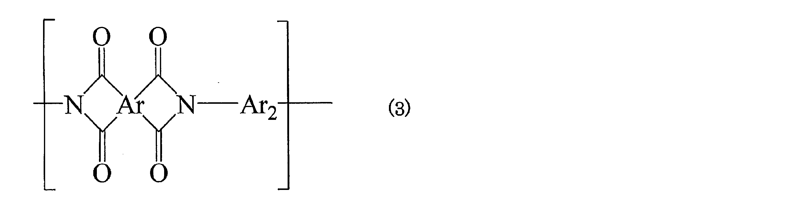
(式(3)中Arは芳香族四塩基酸残基を表し、Ar2は、Ar1以外の芳香族ジアミン残基)
で表される繰り返し単位を含み、かつ、ポリイミド(B)の全ジアミン残基の総量に対して、Ar1が5~30モル%、Ar2が70~95モル%である上記1に記載の銅張積層板。
3. Ar2がC1~C3アルキル基で置換されていてもよいフェニレン基、又は、フェニル基2個が単結合、又は、-CO-、-OCO-、C1-C3アルキレン、-NHCO-又は-NHCO-ph-CONH-からなる群から選ばれる2価の架橋基を介して結合したビスフェニレン基(フェニル基上に、ハロゲノ置換を有してもよいC1~C3のアルキル基又はC1~C3のアルコキシ基を置換基として有していてもよい)である上記2に記載の銅張積層板。
4. Ar2が下記式(4)
で表される繰り返し単位を含み、かつ、ポリイミド(B)の全ジアミン残基の総量に対して、Ar1が5~30モル%、Ar2が70~95モル%である上記1に記載の銅張積層板。
3. Ar2がC1~C3アルキル基で置換されていてもよいフェニレン基、又は、フェニル基2個が単結合、又は、-CO-、-OCO-、C1-C3アルキレン、-NHCO-又は-NHCO-ph-CONH-からなる群から選ばれる2価の架橋基を介して結合したビスフェニレン基(フェニル基上に、ハロゲノ置換を有してもよいC1~C3のアルキル基又はC1~C3のアルコキシ基を置換基として有していてもよい)である上記2に記載の銅張積層板。
4. Ar2が下記式(4)

(式(4)中、R1及びR2はそれぞれ水素原子またはC1~C3のアルキル基を表し、R3はメチル基、エチル基、メトキシ基またはトリフルオロメチル基を表し、X2は酸素原子またはNH基を表す)
に記載のアミン残基よりなる群から選ばれる少なくとも1種のジアミン残基である上記2又は3に記載の銅張積層板。
5. Arが下記式(5)
に記載のアミン残基よりなる群から選ばれる少なくとも1種のジアミン残基である上記2又は3に記載の銅張積層板。
5. Arが下記式(5)

に記載の芳香族四塩基酸残基からなる群から選ばれる少なくとも1つの芳香族四塩基酸残基であり、かつ、ポリイミド(B)の全芳香族四塩基酸残基の総量に対して、該芳香族四塩基酸残基が70~100モル%である上記1~4の何れか一項に記載の銅張積層板。
6. 被覆層におけるNi層及びCr層がスパッタリングにより形成されたものである上記1~5の何れか一項に記載の銅張積層板。
7. 上記1~6のいずれか一項に記載の銅張積層板を用いた配線基板。
7. 上記1~6のいずれか一項に記載の銅張積層板を用いた配線基板。
8. 粗化処理を施されていない銅箔の表面にNi層及びCr層の順にスパッタリングにより被覆層を形成し、被覆層を有する粗化処理を施されていない銅箔(A)を得、
次いで、該銅箔(A)の被覆層上に、下記(i)及び(ii)の成分、
(i)成分:芳香族四塩基酸及び/または芳香族四塩基酸ジアルキルエステル、
(ii)成分:式(1)のArで表される芳香族四塩基酸残基に対応する芳香族四塩基酸二無水物とAr1で表されるジアミン残基に対応するジアミンを含むジアミンとの反応で形成されたポリアミック酸、
を含むポリイミド前駆体(C)層を形成し、加熱処理によりポリイミド前駆体(C)層をイミド化させてポリイミド(B)層とする上記1~6の何れか一項に記載の銅張積層板の製造方法。
次いで、該銅箔(A)の被覆層上に、下記(i)及び(ii)の成分、
(i)成分:芳香族四塩基酸及び/または芳香族四塩基酸ジアルキルエステル、
(ii)成分:式(1)のArで表される芳香族四塩基酸残基に対応する芳香族四塩基酸二無水物とAr1で表されるジアミン残基に対応するジアミンを含むジアミンとの反応で形成されたポリアミック酸、
を含むポリイミド前駆体(C)層を形成し、加熱処理によりポリイミド前駆体(C)層をイミド化させてポリイミド(B)層とする上記1~6の何れか一項に記載の銅張積層板の製造方法。
本発明における被覆層を有する粗化処理を施されていない銅箔(A)と、該被覆層に直接接着するポリイミド(B)層で構成される銅張積層板は、特定の被覆層と特定のポリイミド(B)層との組み合わせにより、特異的な密着性を発現する。その密着性は、該被覆層を構成する金属原子の配列周期と、ポリイミド(B)の柔軟なエーテル結合とイミド基の適切な繰り返し長さが適合しているためであり、過酷な高温、高湿条件下においても高い密着性が維持される。また、本発明の銅張積層板はそれ自体のカールが少ない。更に、接着剤層を介さず金属とポリイミドが直接接着しているため、銅箔をエッチングした後のポリイミドフィルムにカールが無くフラットであり、電気電子材料分野において極めて有用である。特に、エッチングにより銅箔をすべて取り除きポリイミドフィルムのみにした場合においてもカールも少ない。従って、配線基板の材料として非常に実用的である。
本発明において被覆層を形成するために使用される粗化処理を施されていない銅箔としては、表面粗さ(Rz)が2μm以下であれば、圧延銅箔及び電解銅箔のどちらを用いてもよい。通常は圧延銅箔が好ましい。該銅箔の表面(表面粗さRz=2μm以下)を被覆する被覆層は、銅箔基材表面から順に、Ni層、Cr層の順で構成される。被覆層の被覆量はNiが通常15~440μg/dm2の範囲であり、Crが通常15~210μg/dm2の範囲である。また、被覆層の厚さの最大値は通常0.5~5nmであり、かつ最小値は通常最大値の80%以上である。
被覆量、被覆層の厚さ及び被覆層の厚さの均一性(厚さの最小値が最大値の80%以上)が前記の範囲を逸脱すると、ポリイミド(B)層との密着性、エッチング性、柔軟性、銅箔の酸化防止効果等の特性が低下する。特に本発明においては被覆層の厚さの均一性は、本発明の特性を得るために重要である。
また、目的によっては、Niの被覆量は15~300μg/dm2未満、好ましくは20~200μg/dm2程度、より好ましくは40~180μg/dm2程度が好ましい。
Crの被覆量は、15~180μg/dm2未満、好ましくは20~150μg/dm2程度、より好ましくは30~100μg/dm2程度が好ましい。
Ni被覆量及びCr被覆量は、それぞれ上記の範囲であれば限定されない。通常Ni被覆量を1質量部とすると、Cr被覆量は、0.5質量部より多く、1質量部以下の割合が好ましく、より好ましくは、0.6~1質量部の割合である。
被覆層の厚さ(Ni層及びCr層の合計の厚さ)の最大値は、目的によっては、0.5~4nm程度、より好ましくは1~4nm程度が好ましい。場合により、1.5~4nm程度が最も好ましい。
尚、被覆層の厚さは、透過型電子顕微鏡を用いて被覆層の断面を目視で観察することにより測定することができる。被覆層は、スパッタリング法で形成されていることが好ましい。スパッタリング法でのNi層及びCr層の形成には、通常スパッタリング装置が使用される。スパッタリング装置は、上記の被覆層を形成することができるものであれば、市販のものの何れでもよい。特許文献3に具体的に開示されてるメッキ法でNi層、メッキ法又はクロメート処理でCr層を形成した場合には均一な厚さ(被覆層の厚さの最小値が最大値の80%以上)の被覆層を形成することが難しく、ポリイミド(B)層との特異的な密着性が得られない。
被覆量、被覆層の厚さ及び被覆層の厚さの均一性(厚さの最小値が最大値の80%以上)が前記の範囲を逸脱すると、ポリイミド(B)層との密着性、エッチング性、柔軟性、銅箔の酸化防止効果等の特性が低下する。特に本発明においては被覆層の厚さの均一性は、本発明の特性を得るために重要である。
また、目的によっては、Niの被覆量は15~300μg/dm2未満、好ましくは20~200μg/dm2程度、より好ましくは40~180μg/dm2程度が好ましい。
Crの被覆量は、15~180μg/dm2未満、好ましくは20~150μg/dm2程度、より好ましくは30~100μg/dm2程度が好ましい。
Ni被覆量及びCr被覆量は、それぞれ上記の範囲であれば限定されない。通常Ni被覆量を1質量部とすると、Cr被覆量は、0.5質量部より多く、1質量部以下の割合が好ましく、より好ましくは、0.6~1質量部の割合である。
被覆層の厚さ(Ni層及びCr層の合計の厚さ)の最大値は、目的によっては、0.5~4nm程度、より好ましくは1~4nm程度が好ましい。場合により、1.5~4nm程度が最も好ましい。
尚、被覆層の厚さは、透過型電子顕微鏡を用いて被覆層の断面を目視で観察することにより測定することができる。被覆層は、スパッタリング法で形成されていることが好ましい。スパッタリング法でのNi層及びCr層の形成には、通常スパッタリング装置が使用される。スパッタリング装置は、上記の被覆層を形成することができるものであれば、市販のものの何れでもよい。特許文献3に具体的に開示されてるメッキ法でNi層、メッキ法又はクロメート処理でCr層を形成した場合には均一な厚さ(被覆層の厚さの最小値が最大値の80%以上)の被覆層を形成することが難しく、ポリイミド(B)層との特異的な密着性が得られない。
本発明におけるポリイミド(B)層は、銅箔(A)の被覆層上にポリイミド前駆体(C)溶液を塗布した後、加熱によりポリイミド前駆体(C)をイミド化するキャスト法を用いて得ることができる。
ポリイミド前駆体(C)は、下記式(6)
ポリイミド前駆体(C)は、下記式(6)

に記載のジアミンより選ばれる少なくとも1種のジアミン化合物(a)と、任意成分として、式(6)以外の芳香族ジアミン化合物(b)を、芳香族四塩基酸二無水物と反応させて得られるポリアミック酸である。
式(6)で表される好ましいジアミン化合物としては、1、3-ビス-(4-アミノフェノキシ)ベンゼン、1、4-ビス-(4-アミノフェノキシ)ベンゼン、1、3-ビス-(3-アミノフェノキシ)ベンゼン、3,4’-オキシジアニリン及び3,3’-ジアミノ-4,4’-ビフェニルジオール等を挙げることが出来る。
式(6)で表される好ましいジアミン化合物としては、1、3-ビス-(4-アミノフェノキシ)ベンゼン、1、4-ビス-(4-アミノフェノキシ)ベンゼン、1、3-ビス-(3-アミノフェノキシ)ベンゼン、3,4’-オキシジアニリン及び3,3’-ジアミノ-4,4’-ビフェニルジオール等を挙げることが出来る。
式(6)以外の芳香族ジアミン化合物(b)としては、1つ以上の芳香族環にアミノ基が2つ結合した化合物であれば特に制限は無い。それらとしては、フェニル基上にC1~C3アルキル基を有してもよいフェニレンジアミン、フェニル基上に置換基(例えばハロゲノ置換を有してもよいC1~C3のアルキル基又はC1~C3のアルコキシ基等)を有してもよいアミノフェニル基2個が単結合又は、2価の架橋基(例えば、-CO-、-OCO-、C1-C3アルキレン、-NHCO-又は-NHCO-ph-CONH-;phはフェニレン基)を介して結合したビスアミノフェニル化合物等が好ましい。
式(6)以外のより好ましい芳香族ジアミン化合物(b)としては下記式(7)
式(6)以外のより好ましい芳香族ジアミン化合物(b)としては下記式(7)

(式中、R1及びR2はそれぞれ水素原子またはC1~C3のアルキル基を表し、R3はメチル基、エチル基、メトキシ基またはトリフルオロメチル基を表し、X2は酸素原子またはNH基を表す。)
に記載の芳香族ジアミンより選ばれる少なくとも1種を挙げることができる。
式(7)で表される化合物の好ましい具体例としては、3,3’-ジアミノ-4,4’-ビフェニルジオール、p-フェニレンジアミン、m-フェニレンジアミン、4,4’-ジアミノベンズアニライド、2,2’-ジメチルベンジジン、N,N’-ビス(4-アミノフェニル)テレフタルアミド 等を挙げることが出来る。
式(7)以外の芳香族ジアミン化合物(b)の具体例としては、4,4’-ジアミノジフェニルプロパン、3,4’-ジアミノジフェニルプロパン等のジアミノジフェニルプロパン類;4,4’-[1,3-フェニレンビス(1-メチリデン)]ビスアニリン、4,4’-[1,4-フェニレンビス(1-メチリデン)]ビスアニリン等のビスアニリン類;4,4’-ジアミノジフェニルメタン、3,4’-ジアミノジフェニルメタン、2,4’-ジアミノジフェニルメタン等のジアミノジフェニルメタン類;4,4’-ジアミノジフェニルスルフィド、3,4’-ジアミノジフェニルスルフィド等のジアミノジフェニルスルフィド類;4,4’-ジアミノジフェニルスルフォン、3,4’-ジアミノジフェニルスルフォン等のジアミノジフェニルスルフォン類;1,5-ジアミノナフタレン等のジアミノナフタレン類;2,4-ビス(β-アミノ-t- ブチル)トルエン、ビス(p-β-アミノ-t-ブチルフェニル)エーテル等が挙げられ、これら芳香族ジアミン化合物(b)は単独で用いてもよく、2種以上を併用してもよい。
ジアミン化合物(b)の使用量は本発明の効果を損なわない限り特に制限はない。ポリイミド(B)中における全ジアミン成分に占めるジアミン化合物(a)の比率が5~30モル%、ジアミン化合物(b)の比率が70~95モル%となるように使用することが好ましい。
また、ポリイミド(B)中における全ジアミン成分に占めるジアミン化合物(a)の比率が10~30モル%、ジアミン化合物(b)の比率が70~90モル%となるように使用する場合、より好ましい。
に記載の芳香族ジアミンより選ばれる少なくとも1種を挙げることができる。
式(7)で表される化合物の好ましい具体例としては、3,3’-ジアミノ-4,4’-ビフェニルジオール、p-フェニレンジアミン、m-フェニレンジアミン、4,4’-ジアミノベンズアニライド、2,2’-ジメチルベンジジン、N,N’-ビス(4-アミノフェニル)テレフタルアミド 等を挙げることが出来る。
式(7)以外の芳香族ジアミン化合物(b)の具体例としては、4,4’-ジアミノジフェニルプロパン、3,4’-ジアミノジフェニルプロパン等のジアミノジフェニルプロパン類;4,4’-[1,3-フェニレンビス(1-メチリデン)]ビスアニリン、4,4’-[1,4-フェニレンビス(1-メチリデン)]ビスアニリン等のビスアニリン類;4,4’-ジアミノジフェニルメタン、3,4’-ジアミノジフェニルメタン、2,4’-ジアミノジフェニルメタン等のジアミノジフェニルメタン類;4,4’-ジアミノジフェニルスルフィド、3,4’-ジアミノジフェニルスルフィド等のジアミノジフェニルスルフィド類;4,4’-ジアミノジフェニルスルフォン、3,4’-ジアミノジフェニルスルフォン等のジアミノジフェニルスルフォン類;1,5-ジアミノナフタレン等のジアミノナフタレン類;2,4-ビス(β-アミノ-t- ブチル)トルエン、ビス(p-β-アミノ-t-ブチルフェニル)エーテル等が挙げられ、これら芳香族ジアミン化合物(b)は単独で用いてもよく、2種以上を併用してもよい。
ジアミン化合物(b)の使用量は本発明の効果を損なわない限り特に制限はない。ポリイミド(B)中における全ジアミン成分に占めるジアミン化合物(a)の比率が5~30モル%、ジアミン化合物(b)の比率が70~95モル%となるように使用することが好ましい。
また、ポリイミド(B)中における全ジアミン成分に占めるジアミン化合物(a)の比率が10~30モル%、ジアミン化合物(b)の比率が70~90モル%となるように使用する場合、より好ましい。
芳香族四塩基酸二無水物としては、芳香族環に4つのカルボキシル基が結合した構造の化合物の二無水物であれば特に制限は無く、下記する芳香族四塩基酸二無水物(c)及びそれ以外の芳香族四塩基酸二無水物(d)等を何れも使用することが出来る。
本発明においては、前記式(1)におけるArが、下記式(8)
本発明においては、前記式(1)におけるArが、下記式(8)
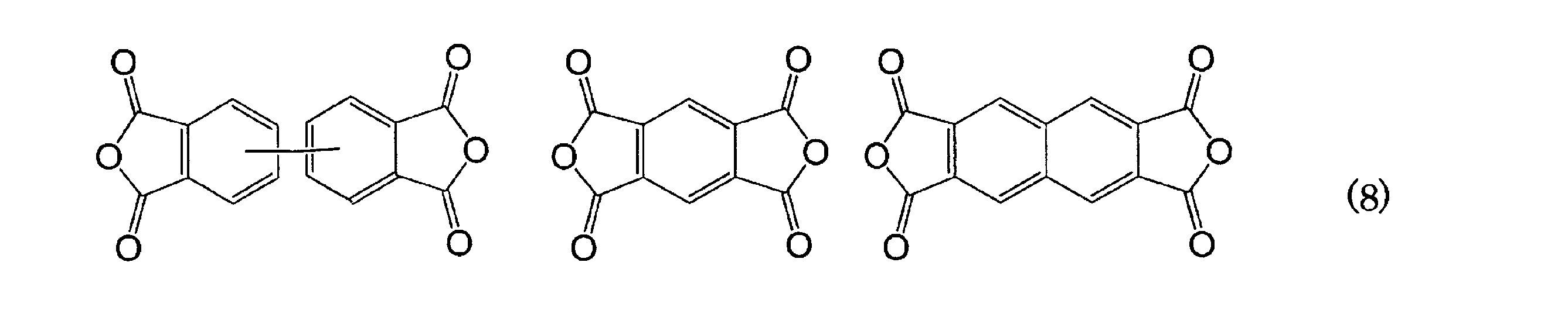
に記載される芳香族四塩基酸二無水物(c)からなる群から選択される少なくとも1つの芳香族四塩基酸二無水物の残基を含むことが好ましい。
上記式(8)で表される芳香族四塩基酸二無水物の名称を挙げると、ビフェニルテトラカルボン酸二無水物、ピロメリット酸二無水物(ピロメリト酸二無水物ともいう)及び2,3,6,7-ナフタレンテトラカルボン酸二無水物である。
上記式(8)で表される芳香族四塩基酸二無水物の名称を挙げると、ビフェニルテトラカルボン酸二無水物、ピロメリット酸二無水物(ピロメリト酸二無水物ともいう)及び2,3,6,7-ナフタレンテトラカルボン酸二無水物である。
芳香族四塩基酸二無水物(c)以外の芳香族四塩基酸二無水物(d)としては、前記(c)以外の芳香族四塩基酸二無水物であればいずれも使用することができる。
上記芳香族四塩基酸二無水物(d)の好ましいものとしては、2個の無水フタル酸基が、2価の架橋基(例えば-O-、-S-、-CO-、-SO2-及びC1-C4アルキレンからなる群から選ばれる架橋基)で結合されたテトラカルボン酸二無水物を挙げることが出来る。より好ましくはオキシジフタル酸二無水物である。
上記芳香族四塩基酸二無水物(d)の具体例としては、3,3’4,4’-オキシジフタル酸二無水物及び2,2’3,3’-オキシジフタル酸二無水物等のオキシジフタル酸二無水物、3,3’4,4’-ベンゾフェノンテトラカルボン酸二無水物、2,3,4,5-チオフェンテトラカルボン酸二無水物、2,2-ビス(3,4-ジカルボキシフェニル)プロパン二無水物、ビス(3,4-ジカルボキシフェニル)スルホン酸二無水物、3,4,9,10-ペリレンテトラカルボン酸二無水物などが挙げられる。
これらの芳香族四塩基酸二無水物は単独で用いてもよく、2種以上を併用してもよい。
本発明においては、芳香族四塩基酸二無水物としては、上記式(8)で表される芳香族四塩基酸二無水物(c)の単独、又は、該芳香族四塩基酸二無水物(c)とその他の芳香族四塩基酸二無水物(d)との組合せが好ましい。
ポリイミド(B)中の全芳香族四塩基酸二無水物成分の総量に対する芳香族四塩基酸二無水物(c)成分の比率は40~100モル%が好ましく、より好ましくは、70~100モル%である。芳香族四塩基酸二無水物(d)成分の比率は0~60モル%、より好ましくは、0~30モル%である。従って、これらの比率を有するポリイミド(B)が得られるように、芳香族四塩基酸二無水物(c)単独、又は(c)及び(d)の両者を用いるのが好ましい。
芳香族四塩基酸二無水物のより好ましい組み合わせとしては、ポリイミド(B)中の全芳香族四塩基酸二無水物成分の総量に対して、ビフェニルテトラカルボン酸二無水物成分を、40~100モル%、より好ましくは、70~100モル%含み、ビフェニルテトラカルボン酸二無水物以外の芳香族四塩基酸二無水物(c)成分(具体的にはピロメリット酸無水物成分又はナフタレンテトラカルボン酸二無水物成分)、及び、芳香族四塩基酸二無水物(d)成分からなる群から選ばれる少なくとも1種を0~60モル%、より好ましくは、0~30モル%含む場合である。この場合、芳香族四塩基酸二無水物(d)成分としては、上記で好ましいとして挙げたテトラカルボン酸二無水物が好ましく、より好ましくは、2個の無水フタル酸基が酸素原子を介して結合しているオキシジフタル酸二無水物である。
芳香族四塩基酸二無水物(c)としてビフェニルテトラカルボン酸二無水物成分を、ポリイミド(B)中の全芳香族四塩基酸二無水物成分の総量に対して、80モル%を超えて~100モル%、より好ましくは90モル%~100モル%、更に好ましくは95~100モル%含む時、耐熱及び/又は耐湿熱試験後のピール強度が1.0N/mm以上で、カールが銅張積層板で、5mm以下のものを得ることができ、非常に好ましい。
従って、これらの比率を有するポリイミド(B)が得られるように、ビフェニルテトラカルボン酸二無水物単独、又は、これと上記好ましい芳香族四塩基酸二無水物(d)として挙げたテトラカルボン酸二無水物の両者を用いるのが好ましい。
上記芳香族四塩基酸二無水物(d)の好ましいものとしては、2個の無水フタル酸基が、2価の架橋基(例えば-O-、-S-、-CO-、-SO2-及びC1-C4アルキレンからなる群から選ばれる架橋基)で結合されたテトラカルボン酸二無水物を挙げることが出来る。より好ましくはオキシジフタル酸二無水物である。
上記芳香族四塩基酸二無水物(d)の具体例としては、3,3’4,4’-オキシジフタル酸二無水物及び2,2’3,3’-オキシジフタル酸二無水物等のオキシジフタル酸二無水物、3,3’4,4’-ベンゾフェノンテトラカルボン酸二無水物、2,3,4,5-チオフェンテトラカルボン酸二無水物、2,2-ビス(3,4-ジカルボキシフェニル)プロパン二無水物、ビス(3,4-ジカルボキシフェニル)スルホン酸二無水物、3,4,9,10-ペリレンテトラカルボン酸二無水物などが挙げられる。
これらの芳香族四塩基酸二無水物は単独で用いてもよく、2種以上を併用してもよい。
本発明においては、芳香族四塩基酸二無水物としては、上記式(8)で表される芳香族四塩基酸二無水物(c)の単独、又は、該芳香族四塩基酸二無水物(c)とその他の芳香族四塩基酸二無水物(d)との組合せが好ましい。
ポリイミド(B)中の全芳香族四塩基酸二無水物成分の総量に対する芳香族四塩基酸二無水物(c)成分の比率は40~100モル%が好ましく、より好ましくは、70~100モル%である。芳香族四塩基酸二無水物(d)成分の比率は0~60モル%、より好ましくは、0~30モル%である。従って、これらの比率を有するポリイミド(B)が得られるように、芳香族四塩基酸二無水物(c)単独、又は(c)及び(d)の両者を用いるのが好ましい。
芳香族四塩基酸二無水物のより好ましい組み合わせとしては、ポリイミド(B)中の全芳香族四塩基酸二無水物成分の総量に対して、ビフェニルテトラカルボン酸二無水物成分を、40~100モル%、より好ましくは、70~100モル%含み、ビフェニルテトラカルボン酸二無水物以外の芳香族四塩基酸二無水物(c)成分(具体的にはピロメリット酸無水物成分又はナフタレンテトラカルボン酸二無水物成分)、及び、芳香族四塩基酸二無水物(d)成分からなる群から選ばれる少なくとも1種を0~60モル%、より好ましくは、0~30モル%含む場合である。この場合、芳香族四塩基酸二無水物(d)成分としては、上記で好ましいとして挙げたテトラカルボン酸二無水物が好ましく、より好ましくは、2個の無水フタル酸基が酸素原子を介して結合しているオキシジフタル酸二無水物である。
芳香族四塩基酸二無水物(c)としてビフェニルテトラカルボン酸二無水物成分を、ポリイミド(B)中の全芳香族四塩基酸二無水物成分の総量に対して、80モル%を超えて~100モル%、より好ましくは90モル%~100モル%、更に好ましくは95~100モル%含む時、耐熱及び/又は耐湿熱試験後のピール強度が1.0N/mm以上で、カールが銅張積層板で、5mm以下のものを得ることができ、非常に好ましい。
従って、これらの比率を有するポリイミド(B)が得られるように、ビフェニルテトラカルボン酸二無水物単独、又は、これと上記好ましい芳香族四塩基酸二無水物(d)として挙げたテトラカルボン酸二無水物の両者を用いるのが好ましい。
本発明の好ましい様態の一つとして、前記芳香族四塩基酸二無水物の一部をアルコール及び/または水と反応させて得られる芳香族四塩基酸ジアルキルエステル(好ましくは芳香族四塩基酸ジC1-C4アルキルエステル)並びに/若しくは芳香族四塩基酸と、両末端にアミノ基を有するポリアミド酸を含有するポリイミド前駆体(C)を加熱によりイミド化する製法が挙げられる。この製法によれば、イミド化により最終的に得られるポリイミド(B)の分子量の低下を伴うことなく、ポリアミド酸の分子量を下げることができるので、ポリイミド前駆体(C)を溶剤に溶解して樹脂ワニスとした場合に、固形分濃度が高く、かつ低粘度で取り扱い易いポリイミド前駆体(C)溶液が得られる。
芳香族四塩基酸ジアルキルエステル並びに/若しくは芳香族四塩基酸とポリイミド前駆体(C)を含む溶液(樹脂ワニス)の固形分濃度は特に制限はないが、通常該溶液の総量に対して15~40質量%程度、好ましくは20~35質量%程度である。
なお、ここでの固形分濃度は、芳香族四塩基酸ジアルキルエステル、芳香族四塩基酸及びポリイミド前駆体(C)の合計濃度を意味する。
通常該樹脂ワニスには、芳香族四塩基酸ジアルキルエステル(好ましくは芳香族四塩基酸ジC1-C4アルキルエステル)を含む方が好ましい。従って、前記芳香族四塩基酸二無水物の一部を予めアルコール(好ましくはC1-C4アルコール)と反応させたものを用いるのが好ましい。この場合、芳香族四塩基酸ジアルキルエステルの生成に伴い、1分子の水が生成されるため、前記芳香族四塩基酸二無水物の一部はこの生成される水と反応して芳香族四塩基酸が共存すると考えられる。しかし、何れもイミド化に際しては、一緒にイミド化されるので支障はない。
また、銅箔(A)の被覆層上にポリイミド前駆体(C)層を形成後、加熱処理によりイミド化してポリイミド(B)とする際に、芳香族四塩基酸ジアルキルエステル{好ましくは芳香族四塩基酸ジ(C1-C4)アルキルエステル}及び/または芳香族四塩基酸が可塑剤として作用することにより、収縮応力が緩和されカールを抑制する効果がある。カールの抑制効果を得るには、反応に用いる全芳香族四塩基酸二無水物成分のうちの3~20モル%をアルコール及び/または水と反応させることが好ましい。アルコール及び/または水と反応させる芳香族四塩基酸二無水物の割合があまり少なすぎる場合には、カール抑制効果が得られない恐れがあり、また多すぎる場合には、ポリイミド前駆体の高分子量化が不充分となり、塗工、乾燥工程でのハンドリングが困難となる恐れがあるので、上記の範囲が好ましい。
尚、2種以上の芳香族四塩基酸二無水物を併用する場合には、いずれの四塩基酸二無水物をアルコール及び/または水と反応させても構わない。
芳香族四塩基酸ジアルキルエステル並びに/若しくは芳香族四塩基酸とポリイミド前駆体(C)を含む溶液(樹脂ワニス)の固形分濃度は特に制限はないが、通常該溶液の総量に対して15~40質量%程度、好ましくは20~35質量%程度である。
なお、ここでの固形分濃度は、芳香族四塩基酸ジアルキルエステル、芳香族四塩基酸及びポリイミド前駆体(C)の合計濃度を意味する。
通常該樹脂ワニスには、芳香族四塩基酸ジアルキルエステル(好ましくは芳香族四塩基酸ジC1-C4アルキルエステル)を含む方が好ましい。従って、前記芳香族四塩基酸二無水物の一部を予めアルコール(好ましくはC1-C4アルコール)と反応させたものを用いるのが好ましい。この場合、芳香族四塩基酸ジアルキルエステルの生成に伴い、1分子の水が生成されるため、前記芳香族四塩基酸二無水物の一部はこの生成される水と反応して芳香族四塩基酸が共存すると考えられる。しかし、何れもイミド化に際しては、一緒にイミド化されるので支障はない。
また、銅箔(A)の被覆層上にポリイミド前駆体(C)層を形成後、加熱処理によりイミド化してポリイミド(B)とする際に、芳香族四塩基酸ジアルキルエステル{好ましくは芳香族四塩基酸ジ(C1-C4)アルキルエステル}及び/または芳香族四塩基酸が可塑剤として作用することにより、収縮応力が緩和されカールを抑制する効果がある。カールの抑制効果を得るには、反応に用いる全芳香族四塩基酸二無水物成分のうちの3~20モル%をアルコール及び/または水と反応させることが好ましい。アルコール及び/または水と反応させる芳香族四塩基酸二無水物の割合があまり少なすぎる場合には、カール抑制効果が得られない恐れがあり、また多すぎる場合には、ポリイミド前駆体の高分子量化が不充分となり、塗工、乾燥工程でのハンドリングが困難となる恐れがあるので、上記の範囲が好ましい。
尚、2種以上の芳香族四塩基酸二無水物を併用する場合には、いずれの四塩基酸二無水物をアルコール及び/または水と反応させても構わない。
本発明において、ジアミン成分の使用割合は、前記芳香族四塩基酸二無水物と前記芳香族四塩基酸ジアルキルエステルの合計モル数100モル%に対して、通常95~105モル%、好ましくは98~102モル%である。ジアミン成分の使用割合がこの範囲を外れると、最終的に得られるポリイミド(B)の高分子量化が不充分となり、強伸度、弾性率、耐屈曲性及び耐熱性などの特性低下を招く恐れがある。
上記範囲でジアミン成分を使用して得られるポリイミド(B)の末端は、使用したジアミン成分の残基若しくは芳香族四塩基酸二無水物の残基がランダムに存在していると考えられる。
上記範囲でジアミン成分を使用して得られるポリイミド(B)の末端は、使用したジアミン成分の残基若しくは芳香族四塩基酸二無水物の残基がランダムに存在していると考えられる。
本発明のポリイミド前駆体(C)溶液は、例えば以下のようにして調製することができる。
予め、反応に用いる芳香族四塩基酸二無水物{(c)及び/または(d)}の一部、好ましくは3~20モル%と、過剰量のアルコール、及びジメチルアミノエタノール又はジエチルアミノエタノール等のジC1-C3アルキルエタノール等の触媒を極性溶剤に溶解させ、室温~100℃で1~5時間攪拌し、四塩基酸ジアルキルエステルを調製する。その後、反応液をいったん室温まで冷却し、ジアミン化合物(a)および必要により任意成分のジアミン化合物(b)を添加し、次いで芳香族四塩基酸二無水物(c)及び/または(d)の残りを添加する。その後、室温~100℃で1~10時間攪拌し、ジアミン成分及び四塩基酸二無水物成分が完全に溶解したのを確認した後、室温に戻すことで本発明のポリイミド前駆体(C)溶液が得られる。
該ポリイミド前駆体(C)溶液は通常固形分濃度が、通常該溶液の総量に対して15~40質量%程度、好ましくは20~35質量%程度である。該ポリイミド前駆体(C)の含量は、固形分の総量に対して80~100質量%が好ましく、より好ましくは90~100質量%であり、更に好ましくは95~100質量%である。
上記で得られたポリイミド前駆体(C)溶液の粘度は25℃で、通常5000~30000mPa・sが好ましく、より好ましくは6000~25000mPa・sである。
予め、反応に用いる芳香族四塩基酸二無水物{(c)及び/または(d)}の一部、好ましくは3~20モル%と、過剰量のアルコール、及びジメチルアミノエタノール又はジエチルアミノエタノール等のジC1-C3アルキルエタノール等の触媒を極性溶剤に溶解させ、室温~100℃で1~5時間攪拌し、四塩基酸ジアルキルエステルを調製する。その後、反応液をいったん室温まで冷却し、ジアミン化合物(a)および必要により任意成分のジアミン化合物(b)を添加し、次いで芳香族四塩基酸二無水物(c)及び/または(d)の残りを添加する。その後、室温~100℃で1~10時間攪拌し、ジアミン成分及び四塩基酸二無水物成分が完全に溶解したのを確認した後、室温に戻すことで本発明のポリイミド前駆体(C)溶液が得られる。
該ポリイミド前駆体(C)溶液は通常固形分濃度が、通常該溶液の総量に対して15~40質量%程度、好ましくは20~35質量%程度である。該ポリイミド前駆体(C)の含量は、固形分の総量に対して80~100質量%が好ましく、より好ましくは90~100質量%であり、更に好ましくは95~100質量%である。
上記で得られたポリイミド前駆体(C)溶液の粘度は25℃で、通常5000~30000mPa・sが好ましく、より好ましくは6000~25000mPa・sである。
反応に用い得るアルコールとしては、メタノール、エタノール、プロパノール、イソプロパノール、n-ブタノール、2-ブタノール、t-ブタノール、など一価のアルコールであれば種類を問わないが、コストや扱いやすさの観点から、C1~C4のアルコールが好ましい。アルコールの添加量は、最初に加えた芳香族四塩基酸二無水物(c)及び/または(d)を確実にジアルキルエステル化するために、反応に用いる芳香族四塩基酸二無水物(c)及び/または(d)の2~4倍モル量を添加するのが好ましい。四塩基酸ジアルキルエステル合成時における加熱時間及び温度は、上述の範囲内であれば特に限定されないが、反応を確実に進行させるためには50℃以上で2~5時間攪拌するのが好ましい。また、ポリイミド前駆体(C)の合成時に並行して起こるイミド化反応によるポリマーの析出を抑制するため、加熱温度が70℃以下であることが好ましい。
反応に用い得る極性溶剤としては、原料である芳香族四塩基酸二無水物成分やジアミン成分、及び中間生成物である芳香族四塩基酸ジアルキルエステルや最終生成物であるポリイミド前駆体(C)を溶解するものなら特に限定されず、例えばN-メチル-2-ピロリドン、N,N-ジメチルホルムアミド、N-メチルホルムアミド、N,N-ジメチルアセトアミド、ヘキサメチルフォスフォラミドなどのアミド系溶剤や、2-メトキシエタノール、2-エトキシエタノール、2-(メトキシメトキシ)エトキシエタノール、2-イソプロポキシエタノール、2-ブトキシエタノール、テトラヒドロフルフリルアルコールなどのエーテル系溶剤、またはγ-ブチロラクトン、メチルベンゾエートなどのエステル系溶剤、ジメチルスルホキシドなどが挙げられる。原料成分及び生成物の溶解能力が高いことや、価格が安いことからN-メチル-2-ピロリドン、N,N-ジメチルホルムアミド、N,N-ジメチルアセトアミドなどのアミド系溶剤が好ましい。これら極性溶剤は、1種のみで用いてもよく、2種以上を併用してもよい。
本発明におけるポリイミド前駆体(C)溶液の粘度は、銅箔に塗工する際の塗工性の点から、固形分濃度が15~35質量%、好ましくは20~32%濃度の場合、測定温度25℃において、通常5000~30000mPa・sであり、好ましくは6000~25000mPa・sであり、より好ましくは7000~20000mPa・sである。反応に用いる極性溶剤の量を調節することにより、液粘度を上述の値に収めることができる。
こうして得られた本発明のポリイミド前駆体(C)溶液には、本発明の効果を損なわない範囲で種々の添加剤、例えば、芳香族ポリアミド樹脂、フェノール樹脂等の有機添加剤、またはシリカ化合物等の無機添加剤、顔料、染料、ハレーション防止剤、蛍光増白剤、界面活性剤、レベリング剤、可塑剤、難燃剤、酸化防止剤、充填剤、静電防止剤、粘度調整剤、イミド化触媒、促進剤、脱水剤、イミド化遅延剤、光安定剤、光触媒、低誘電体、導電体、磁性体や、熱分解性化合物等を含有することができる。
前述のポリイミド前駆体(C)溶液を、銅箔(A)の被覆層上に塗工し、乾燥後加熱処理を施すことによって、本発明の銅張積層板を得ることができる。その実施方法の具体例としては、まず、加熱によるイミド化後の膜厚が通常3~100μm、好ましくは5~50μmとなる量のポリイミド前駆体(C)溶液を該被覆層上に塗工し、次いで乾燥及び加熱処理によるイミド化を行う。乾燥条件は通常50~150℃で5~180分間、好ましくは100~140℃で8~30分間であり、加熱条件は通常100~500℃で0.5~5時間、好ましくは250~400℃で1~3時間である。
本発明の銅張積層板において、銅箔(A)における被覆層とポリイミド(B)層の界面での接着強度は、実用上、通常(温度約25℃)の雰囲気下で、通常0.7N/mm以上、好ましくは0.9N/mm以上、より好ましくは1.0N/mm以上、更に好ましくは、1.2N/mm以上、最も好ましくは、1.3N/mm以上である。上限は特にないが、通常2N/mm程度である。150℃程度の高温条件下で例えば168時間保持した後や40℃、湿度95%(95%RHと表示する)、等の高温高湿条件下で保持した後においても、0.7N/mm以上であることが好ましく、より好ましくは0.9N/mm以上であり、更に好ましくは1.0N/mm以上である。1.3N/mm以上が特に好ましい。
本発明の銅張積層板は、5cm角(5cm square)(一辺が5cmの正方形:以下同じ)に切り出したときに生じる四隅の反りの高さの平均値、すなわち銅張積層板のカールが、10mm以下であることが好ましく、5mm以下であることがより好ましい。また本発明の銅張積層板は、該銅張積層板の銅箔を全面エッチングして得られるポリイミドフィルムを、5cm角に切り出したときに生じる四隅の反りの高さの平均値、すなわちポリイミドフィルムのカールが、10mm以下であることが好ましく、5mm以下であることがより好ましい。
本発明の銅張積層板に、打ち抜き、エッチング、穴開け、メッキなどの加工を行うことにより、本発明の一様態であるフレキシブルプリント基板用の配線板を得ることができる。 本発明の好ましい銅張積層板として、下記するものを挙げることが出来る。
(I) 前記本発明(前記課題を解決するための手段の項における1又は2に記載の発明)の銅張積層板において、ポリイミド(B)が、前記式(1)及び前記式(3)で表される繰り返し単位の両者を含み、ポリイミド(B)中の全繰り返し単位の総量に対して、式(1)の繰り返し単位の総量が、5~30モル%であり、式(3)の繰り返し単位の総量が70~95モル%である銅張積層板。
なお、上記の繰り返し単位の比率は、前記した全アミン残基に対するAr1で表されるアミン残基及びAr2で表されるアミン残基の比率と同じである。従って、上記の繰り返し単位のモル比率は、Ar1で表されるアミン残基及びAr2で表されるアミン残基の比率で置き換えることも出来る。
(II) Ar1で表されるアミン残基が、ビス(3又は4-アミノフェノキシ)ベンゼン、4,4’-、及び3,4’-オキシジアニリンからなる群から選ばれる少なくとも一つのジアミンの残基であり、Ar2で表されるアミン残基がm-及びp-フェニレンジアミン、ジアミノベンズアニライド、C1-C2アルキル置換を有してもよい4,4’-ジアミノビフェニル(ベンジジン)及び、N、N’-ビス(4-アミノフェニル)テレフタルアミド、からなる群から選ばれる少なくとも一つのジアミンの残基である上記(I)に記載の銅張積層板。
(III) Ar1で表されるアミン残基が、1,4又は1,3-ビス(4-アミノフェノキシ)ベンゼンの残基であり、Ar2で表されるアミン残基がm-及びp-フェニレンジアミン、4,4’-ジアミノベンズアニライド、及び、2,2’-ジメチル-4,4’-ジアミノビフェニル(ベンジジジン)からなる群から選ばれる少なくとも一つのジアミンの残基である上記(II)に記載の銅張積層板。
(I) 前記本発明(前記課題を解決するための手段の項における1又は2に記載の発明)の銅張積層板において、ポリイミド(B)が、前記式(1)及び前記式(3)で表される繰り返し単位の両者を含み、ポリイミド(B)中の全繰り返し単位の総量に対して、式(1)の繰り返し単位の総量が、5~30モル%であり、式(3)の繰り返し単位の総量が70~95モル%である銅張積層板。
なお、上記の繰り返し単位の比率は、前記した全アミン残基に対するAr1で表されるアミン残基及びAr2で表されるアミン残基の比率と同じである。従って、上記の繰り返し単位のモル比率は、Ar1で表されるアミン残基及びAr2で表されるアミン残基の比率で置き換えることも出来る。
(II) Ar1で表されるアミン残基が、ビス(3又は4-アミノフェノキシ)ベンゼン、4,4’-、及び3,4’-オキシジアニリンからなる群から選ばれる少なくとも一つのジアミンの残基であり、Ar2で表されるアミン残基がm-及びp-フェニレンジアミン、ジアミノベンズアニライド、C1-C2アルキル置換を有してもよい4,4’-ジアミノビフェニル(ベンジジン)及び、N、N’-ビス(4-アミノフェニル)テレフタルアミド、からなる群から選ばれる少なくとも一つのジアミンの残基である上記(I)に記載の銅張積層板。
(III) Ar1で表されるアミン残基が、1,4又は1,3-ビス(4-アミノフェノキシ)ベンゼンの残基であり、Ar2で表されるアミン残基がm-及びp-フェニレンジアミン、4,4’-ジアミノベンズアニライド、及び、2,2’-ジメチル-4,4’-ジアミノビフェニル(ベンジジジン)からなる群から選ばれる少なくとも一つのジアミンの残基である上記(II)に記載の銅張積層板。
(IV) Ar1で表されるアミン残基が、1,3-ビス(4-アミノフェノキシ)ベンゼンの残基であり、Ar2で表されるアミン残基がp-フェニレンジアミンである上記(III)に記載の銅張積層板。
(V) 前記式(1)及び前記式(3)におけるArが、それぞれ独立に、オキシジフタル酸二無水物、ビフェニルテトラカルボン酸二無水物、ピロメリト酸二無水物、及びナフタレンテトラカルボン酸二無水物からなる群から選ばれる芳香族四塩基酸の残基である上記(I)~(IV)の何れか一項に記載の銅張積層板。
(VI) ビフェニルテトラカルボン酸二無水物が3,3’,4,4’-ビフェニルテトラカルボン酸二無水物及び2,3,3’,4’-ビフェニルテトラカルボン酸二無水物であり、ナフタレンテトラカルボン酸二無水物が2,3,6,7-ナフタレンテトラカルボン酸二無水物である上記(V)に記載の銅張積層板。
(VII) 前記式(1)におけるArが3,3’,4,4’-ビフェニルテトラカルボン酸二無水物であり、前記式(3)におけるArが3,3’,4,4’-ビフェニルテトラカルボン酸二無水物、ピロメリト酸二無水物、3,3’,4,4’-オキシジフタル酸二酸無水物及び2,3,6,7-ナフタレンテトラカルボン酸二無水物からなる群から選ばれる芳香族四塩基酸の残基である(IV)~(V)の何れか一項に記載の銅張積層板。
(VIII) 前記式(3)におけるArが3,3’,4,4’-ビフェニルテトラカルボン酸二無水物又は3,3’,4,4’-オキシジフタル酸二酸無水物である上記(VII)に記載の銅張積層板。
(V) 前記式(1)及び前記式(3)におけるArが、それぞれ独立に、オキシジフタル酸二無水物、ビフェニルテトラカルボン酸二無水物、ピロメリト酸二無水物、及びナフタレンテトラカルボン酸二無水物からなる群から選ばれる芳香族四塩基酸の残基である上記(I)~(IV)の何れか一項に記載の銅張積層板。
(VI) ビフェニルテトラカルボン酸二無水物が3,3’,4,4’-ビフェニルテトラカルボン酸二無水物及び2,3,3’,4’-ビフェニルテトラカルボン酸二無水物であり、ナフタレンテトラカルボン酸二無水物が2,3,6,7-ナフタレンテトラカルボン酸二無水物である上記(V)に記載の銅張積層板。
(VII) 前記式(1)におけるArが3,3’,4,4’-ビフェニルテトラカルボン酸二無水物であり、前記式(3)におけるArが3,3’,4,4’-ビフェニルテトラカルボン酸二無水物、ピロメリト酸二無水物、3,3’,4,4’-オキシジフタル酸二酸無水物及び2,3,6,7-ナフタレンテトラカルボン酸二無水物からなる群から選ばれる芳香族四塩基酸の残基である(IV)~(V)の何れか一項に記載の銅張積層板。
(VIII) 前記式(3)におけるArが3,3’,4,4’-ビフェニルテトラカルボン酸二無水物又は3,3’,4,4’-オキシジフタル酸二酸無水物である上記(VII)に記載の銅張積層板。
(IX) 被覆層におけるNi被覆量が、dm2当たり、15μg以上で、300μg未満である、上記(I)~(VIII)の何れか一項に記載の銅張積層板。
(X) 被覆層におけるNi被覆量が、20~200μg/dm2である上記(IX)に記載の銅張積層板。
(XI) 被覆層におけるCr被覆量の割合が、Ni被覆量を基準(質量)として、0.5より多く、1以下である上記(I)~(IX)の何れか一項に記載の銅張積層板。
(XII) 前記(1)~(3)の条件を満たす被覆層を有する粗化処理を施されていない銅箔(A)と、該被覆層に直接接着するポリイミド(B)層との常態剥離強度(後記)が0.9N/mm以上である上記(I)~(XI)の何れか一項に記載の銅張積層板。
(XIII) 常態剥離強度が1.2N/mm以上である上記(XII)に記載の銅張積層板。
(XIV) 銅張積層板のカールが、5cm角に切り出したときに生じる四隅の反りの高さの平均値が10mm以下である上記(I)~(XIII)の何れか一項に記載の銅張積層板。
(XV) 銅張積層板のカールが、5cm角に切り出したときに生じる四隅の反りの高さの平均値が5mm以下である上記(I)~(XIII)の何れか一項に記載の銅張積層板。
(XVI) ポリイミド(B)が、前記式(1)及び式(3)で表される繰り返し単位を含むポリイミドであり、ポリイミド(B)層が、該ポリイミドに対応するポリイミド前駆体(C)層の加熱処理により形成されたものである上記(I)~(XV)の何れか一項に記載の銅張積層板。
(X) 被覆層におけるNi被覆量が、20~200μg/dm2である上記(IX)に記載の銅張積層板。
(XI) 被覆層におけるCr被覆量の割合が、Ni被覆量を基準(質量)として、0.5より多く、1以下である上記(I)~(IX)の何れか一項に記載の銅張積層板。
(XII) 前記(1)~(3)の条件を満たす被覆層を有する粗化処理を施されていない銅箔(A)と、該被覆層に直接接着するポリイミド(B)層との常態剥離強度(後記)が0.9N/mm以上である上記(I)~(XI)の何れか一項に記載の銅張積層板。
(XIII) 常態剥離強度が1.2N/mm以上である上記(XII)に記載の銅張積層板。
(XIV) 銅張積層板のカールが、5cm角に切り出したときに生じる四隅の反りの高さの平均値が10mm以下である上記(I)~(XIII)の何れか一項に記載の銅張積層板。
(XV) 銅張積層板のカールが、5cm角に切り出したときに生じる四隅の反りの高さの平均値が5mm以下である上記(I)~(XIII)の何れか一項に記載の銅張積層板。
(XVI) ポリイミド(B)が、前記式(1)及び式(3)で表される繰り返し単位を含むポリイミドであり、ポリイミド(B)層が、該ポリイミドに対応するポリイミド前駆体(C)層の加熱処理により形成されたものである上記(I)~(XV)の何れか一項に記載の銅張積層板。
以下、合成例及び実施例によって本発明を更に詳細に説明するが、本発明はこれらの実施例に限定されるものではない。なお、以下の実施例における物性の評価方法、及び実施例で用いた各原料のメーカーは下記のとおりである。
・ ポリイミド前駆体(C)溶液の粘度
E型粘度計(東機産業株式会社製)を用いて25℃で測定した値。
・ 銅箔、銅張積層板、及びポリイミドフィルムの膜厚
Digimicro stand MS-11C(株式会社ニコン製)を用いて測定した値。
・ 銅箔の剥離強度(ピール強度)
銅張積層板の銅箔側に、マスキングテープ(商品名 クリアーラインテープ No.557、ニチバン株式会社製、)を貼り付けた後、40℃に加熱したエッチング液(塩化第二鉄水溶液ボーメ比重45度)中で30分間エッチングを行い、マスキングテープを剥離することで10mm幅の銅箔パターンを形成した。次いで、両面テープを用いてポリイミド樹脂層側を補強板に貼り付け、カッターナイフを用いて10mm幅の銅箔の端部をポリイミド樹脂から剥がし、テンシロン試験機(AUTOGRAPH、株式会社島津製作所製)を用いて90°方向での銅箔とポリイミド樹脂層との剥離強度を測定し、これを常態ピール強度とした。なお、常態とは、出来た銅張積層板を、常温(25℃)に置いた状態を意味する。また、該積層板を150℃で168時間保持した後の剥離強度を耐熱ピール強度とし、40℃、95%RHで96時間保持した後の剥離強度を耐湿熱ピール強度とした。
・ ポリイミド前駆体(C)溶液の粘度
E型粘度計(東機産業株式会社製)を用いて25℃で測定した値。
・ 銅箔、銅張積層板、及びポリイミドフィルムの膜厚
Digimicro stand MS-11C(株式会社ニコン製)を用いて測定した値。
・ 銅箔の剥離強度(ピール強度)
銅張積層板の銅箔側に、マスキングテープ(商品名 クリアーラインテープ No.557、ニチバン株式会社製、)を貼り付けた後、40℃に加熱したエッチング液(塩化第二鉄水溶液ボーメ比重45度)中で30分間エッチングを行い、マスキングテープを剥離することで10mm幅の銅箔パターンを形成した。次いで、両面テープを用いてポリイミド樹脂層側を補強板に貼り付け、カッターナイフを用いて10mm幅の銅箔の端部をポリイミド樹脂から剥がし、テンシロン試験機(AUTOGRAPH、株式会社島津製作所製)を用いて90°方向での銅箔とポリイミド樹脂層との剥離強度を測定し、これを常態ピール強度とした。なお、常態とは、出来た銅張積層板を、常温(25℃)に置いた状態を意味する。また、該積層板を150℃で168時間保持した後の剥離強度を耐熱ピール強度とし、40℃、95%RHで96時間保持した後の剥離強度を耐湿熱ピール強度とした。
・ 銅張積層板のカール
得られた銅張積層板を5cm×5cm角に切り出し、反っている方向を上にして水平な台に置き、4つの角の浮き上がり高さを測定し、その平均をエッチング前のカールの測定値とした。
・ ポリイミドフィルムのカール
得られた銅張積層板の銅箔を全面エッチングしてポリイミドフィルムを作成した後、5cm×5cm角に切り出し、反っている方向を上にして水平な台に置き、4つの角の浮き上がり高さを測定し、その平均をポリイミドフィルムのカールの測定値とした。
・ 原料メーカー
1、3-ビス-(4-アミノフェノキシ)ベンゼン :和歌山精化工業株式会社
1、4-ビス-(4-アミノフェノキシ)ベンゼン :和歌山精化工業株式会社
1、3-ビス-(3-アミノフェノキシ)ベンゼン :三井化学株式会社
3,4’-オキシジアニリン :JFEケミカル株式会社
3,3’-ジアミノ-4,4’-ビフェニルジオール :日本化薬株式会社
p-フェニレンジアミン :大新化成工業株式会社
m-フェニレンジアミン :昭和化学株式会社
4,4’-ジアミノベンズアニライド :日本純良薬品株式会社
2,2’-ジメチルベンジジン :和歌山精化工業株式会社
N,N’-ビス(4-アミノフェニル)テレフタルアミド :日本純良薬品株式会社
3,3’,4,4’-ビフェニルテトラカルボン酸二無水物:三菱化学株式会社
2,3,3’,4’-ビフェニルテトラカルボン酸二無水物:東レ・ファインケミカル株式会社
ピロメリト酸二無水物 :三菱ガス化学株式会社
2,3,6,7-ナフタレンテトラカルボン酸二無水物 :JFEケミカル株式会社
得られた銅張積層板を5cm×5cm角に切り出し、反っている方向を上にして水平な台に置き、4つの角の浮き上がり高さを測定し、その平均をエッチング前のカールの測定値とした。
・ ポリイミドフィルムのカール
得られた銅張積層板の銅箔を全面エッチングしてポリイミドフィルムを作成した後、5cm×5cm角に切り出し、反っている方向を上にして水平な台に置き、4つの角の浮き上がり高さを測定し、その平均をポリイミドフィルムのカールの測定値とした。
・ 原料メーカー
1、3-ビス-(4-アミノフェノキシ)ベンゼン :和歌山精化工業株式会社
1、4-ビス-(4-アミノフェノキシ)ベンゼン :和歌山精化工業株式会社
1、3-ビス-(3-アミノフェノキシ)ベンゼン :三井化学株式会社
3,4’-オキシジアニリン :JFEケミカル株式会社
3,3’-ジアミノ-4,4’-ビフェニルジオール :日本化薬株式会社
p-フェニレンジアミン :大新化成工業株式会社
m-フェニレンジアミン :昭和化学株式会社
4,4’-ジアミノベンズアニライド :日本純良薬品株式会社
2,2’-ジメチルベンジジン :和歌山精化工業株式会社
N,N’-ビス(4-アミノフェニル)テレフタルアミド :日本純良薬品株式会社
3,3’,4,4’-ビフェニルテトラカルボン酸二無水物:三菱化学株式会社
2,3,3’,4’-ビフェニルテトラカルボン酸二無水物:東レ・ファインケミカル株式会社
ピロメリト酸二無水物 :三菱ガス化学株式会社
2,3,6,7-ナフタレンテトラカルボン酸二無水物 :JFEケミカル株式会社
作製例1(本発明に使用する被覆層を有する銅箔(A)の作製)
銅箔基材として、無粗化処理の圧延銅箔(JX日鉱日石金属株式会社製C1100、厚さ18μm、表面粗さ(Rz)0.7μm)を用い、この銅箔の片面からあらかじめ付着している薄い酸化膜をArイオンガンにより取り除いた後、Ni層及びCr層をそれぞれ1nmの厚さになるように連続スパッタリング装置で順に成膜した。Ni及びCrのそれぞれの被覆量は、Ni:85μg/dm2であり、Cr:70μg/dm2であった。また、Ni層及びCr層を合わせた被覆層の厚さの最大値は2.1nmであり、最小値は1.9nm(最大値に対する最小値の割合:約90%)であった。この銅箔をA-1とする。
銅箔基材として、無粗化処理の圧延銅箔(JX日鉱日石金属株式会社製C1100、厚さ18μm、表面粗さ(Rz)0.7μm)を用い、この銅箔の片面からあらかじめ付着している薄い酸化膜をArイオンガンにより取り除いた後、Ni層及びCr層をそれぞれ1nmの厚さになるように連続スパッタリング装置で順に成膜した。Ni及びCrのそれぞれの被覆量は、Ni:85μg/dm2であり、Cr:70μg/dm2であった。また、Ni層及びCr層を合わせた被覆層の厚さの最大値は2.1nmであり、最小値は1.9nm(最大値に対する最小値の割合:約90%)であった。この銅箔をA-1とする。
尚、酸化膜の除去条件及びスパッタリングの条件、被覆量の測定方法及び被覆層の厚さ測定は下記の通りである。
* 酸化膜の除去条件及びスパッタリングの条件
・ 装置:連続スパッタリング装置(株式会社アルバック製)
・ イオンガン電力:600W
・ イオンガンArガス圧:6.0×10⁻²Pa
・ スパッタArガス圧:0.3Pa
・ 到達真空度:1.0×10⁻⁵Pa
・ ターゲット:
Ni層用=Ni(純度3N)
Cr層用=Cr(純度3N)
・ スパッタリング電力:Ni 1.9kW、Cr 1.8kW
* 被覆量の測定
50mm×50mmの銅箔表面の皮膜をHNO3(2重量%)とHCl(5重量%)を混合した溶液に溶解し、その溶液中の金属濃度をICP発光分光分析装置(エスアイアイ・ナノテクノロジー株式会社製、SFC-3100)にて定量し、単位面積当たりの金属量(μg/dm2)を算出した。
* 被覆層の厚さ測定
被覆層を透過型電子顕微鏡(TEM)によって観察したときのTEMの測定条件を以下に示す。観察視野中に写っている被覆層全体から、幅50nmの被覆層を任意に選択し、その50nmの間における厚みの最大値及び最小値を測定した。この測定を任意に選択した3視野について行い、作製された銅箔における被覆層の厚みの最大値及び最小値を求めた。また、被覆層の厚みについて、最大値に対する最小値の割合を百分率で求めた。
TEMの測定条件
・ 装置:TEM(株式会社日立製作所製、型式H9000NAR)
・ 加速電圧:300kV
・ 倍率:300000倍
・ 観察視野:60nm×60nm
* 酸化膜の除去条件及びスパッタリングの条件
・ 装置:連続スパッタリング装置(株式会社アルバック製)
・ イオンガン電力:600W
・ イオンガンArガス圧:6.0×10⁻²Pa
・ スパッタArガス圧:0.3Pa
・ 到達真空度:1.0×10⁻⁵Pa
・ ターゲット:
Ni層用=Ni(純度3N)
Cr層用=Cr(純度3N)
・ スパッタリング電力:Ni 1.9kW、Cr 1.8kW
* 被覆量の測定
50mm×50mmの銅箔表面の皮膜をHNO3(2重量%)とHCl(5重量%)を混合した溶液に溶解し、その溶液中の金属濃度をICP発光分光分析装置(エスアイアイ・ナノテクノロジー株式会社製、SFC-3100)にて定量し、単位面積当たりの金属量(μg/dm2)を算出した。
* 被覆層の厚さ測定
被覆層を透過型電子顕微鏡(TEM)によって観察したときのTEMの測定条件を以下に示す。観察視野中に写っている被覆層全体から、幅50nmの被覆層を任意に選択し、その50nmの間における厚みの最大値及び最小値を測定した。この測定を任意に選択した3視野について行い、作製された銅箔における被覆層の厚みの最大値及び最小値を求めた。また、被覆層の厚みについて、最大値に対する最小値の割合を百分率で求めた。
TEMの測定条件
・ 装置:TEM(株式会社日立製作所製、型式H9000NAR)
・ 加速電圧:300kV
・ 倍率:300000倍
・ 観察視野:60nm×60nm
作製例2(メッキ法により被覆層を形成した比較用の銅箔の作製)
銅箔基材として、無粗化処理の圧延銅箔(JX日鉱日石金属株式会社製C1100、厚さ18μm、表面粗さ(Rz)0.7μm)を用い、この銅箔の片面から作製例1の方法に準じてあらかじめ付着している薄い酸化膜をArイオンガンにより取り除いた後、Ni層及びCr層がそれぞれ約1nmの厚さになるように、Ni電気メッキ及びクロメート処理を順に施した。Ni層及びCr層を合わせた被覆層の厚さの最大値は3.0nmであり、最小値は0.5nmであった。
この銅箔をA-2とする。尚、Ni電気メッキ及びクロメート処理の条件は下記のとおりである。
(1)Niメッキ
・ メッキ浴:スルファミン酸ニッケル(Ni2+として110g/L)、H3BO3(40g/L)
・ 電流密度:1.0A/dm2
・ 浴温:55℃
・ Ni量:95μg/dm2(厚み約1.1nm)
(2)クロメート処理
・ メッキ浴:CrO2(1g/L)、Zn(粉末0.4g)、Na2SO4(10g/L)
・ 電流密度:2.0A/dm2
・ 浴温:55℃
・ Cr量:70μg/dm2(作製例1とほぼ同量のCr量)
銅箔基材として、無粗化処理の圧延銅箔(JX日鉱日石金属株式会社製C1100、厚さ18μm、表面粗さ(Rz)0.7μm)を用い、この銅箔の片面から作製例1の方法に準じてあらかじめ付着している薄い酸化膜をArイオンガンにより取り除いた後、Ni層及びCr層がそれぞれ約1nmの厚さになるように、Ni電気メッキ及びクロメート処理を順に施した。Ni層及びCr層を合わせた被覆層の厚さの最大値は3.0nmであり、最小値は0.5nmであった。
この銅箔をA-2とする。尚、Ni電気メッキ及びクロメート処理の条件は下記のとおりである。
(1)Niメッキ
・ メッキ浴:スルファミン酸ニッケル(Ni2+として110g/L)、H3BO3(40g/L)
・ 電流密度:1.0A/dm2
・ 浴温:55℃
・ Ni量:95μg/dm2(厚み約1.1nm)
(2)クロメート処理
・ メッキ浴:CrO2(1g/L)、Zn(粉末0.4g)、Na2SO4(10g/L)
・ 電流密度:2.0A/dm2
・ 浴温:55℃
・ Cr量:70μg/dm2(作製例1とほぼ同量のCr量)
実施例1
温度計、環流冷却器、粉体導入口、窒素導入装置及び攪拌装置のついた300mlの反応器に、3,3’,4,4’-ビフェニルテトラカルボン酸二無水物1.696g、2-ジメチルアミノエタノール0.0193g、メタノール0.443g及びN-メチル-2-ピロリドン92.5gを加え、70℃で2時間攪拌して均一な溶液になったことを確認した後、室温まで冷却した。これにp-フェニレンジアミン5.845g及び1,3-ビス-(4-アミノフェノキシ)ベンゼン5.267gを加え、次いで反応液の温度が70℃を超えないように3,3’,4,4’-ビフェニルテトラカルボン酸二無水物19.507gを徐々に加えた。その後、70℃で3時間攪拌し、室温に戻すことにより、固形分濃度が26.0%のポリイミド前駆体溶液125gを得た。得られた溶液の粘度を表1に示した。
銅箔A-1の被覆層上に、オートマチックアプリケーター(株式会社安田精機製作所製)を用いて、加熱ポリイミド化後のポリイミド層の膜厚が25μmとなる量のポリイミド前駆体溶液を塗布し、その後130℃で10分間乾燥し、更に350℃で2時間の加熱処理することによりイミド化した。得られた本発明の銅張積層板を評価し、その評価結果を表2に示した。
温度計、環流冷却器、粉体導入口、窒素導入装置及び攪拌装置のついた300mlの反応器に、3,3’,4,4’-ビフェニルテトラカルボン酸二無水物1.696g、2-ジメチルアミノエタノール0.0193g、メタノール0.443g及びN-メチル-2-ピロリドン92.5gを加え、70℃で2時間攪拌して均一な溶液になったことを確認した後、室温まで冷却した。これにp-フェニレンジアミン5.845g及び1,3-ビス-(4-アミノフェノキシ)ベンゼン5.267gを加え、次いで反応液の温度が70℃を超えないように3,3’,4,4’-ビフェニルテトラカルボン酸二無水物19.507gを徐々に加えた。その後、70℃で3時間攪拌し、室温に戻すことにより、固形分濃度が26.0%のポリイミド前駆体溶液125gを得た。得られた溶液の粘度を表1に示した。
銅箔A-1の被覆層上に、オートマチックアプリケーター(株式会社安田精機製作所製)を用いて、加熱ポリイミド化後のポリイミド層の膜厚が25μmとなる量のポリイミド前駆体溶液を塗布し、その後130℃で10分間乾燥し、更に350℃で2時間の加熱処理することによりイミド化した。得られた本発明の銅張積層板を評価し、その評価結果を表2に示した。
実施例2
温度計、環流冷却器、粉体導入口、窒素導入装置及び攪拌装置のついた300mlの反応器に、3,3’,4,4’-ビフェニルテトラカルボン酸二無水物1.769g、2-ジメチルアミノエタノール0.0201g、メタノール0.462g及びN-メチル-2-ピロリドン92.5gを加え、70℃で2時間攪拌して均一な溶液になったことを確認した後、室温まで冷却した。これにp-フェニレンジアミン6.906g及び1,3-ビス-(4-アミノフェノキシ)ベンゼン3.295gを加え、次いで反応液の温度が70℃を超えないように3,3’,4,4’-ビフェニルテトラカルボン酸二無水物20.338gを徐々に加えた。その後、70℃で3時間攪拌し、室温に戻すことにより、固形分濃度が26%のポリイミド前駆体溶液125gを得た。得られた溶液の粘度を表1に示した。
銅箔A-1の被覆層上に、オートマチックアプリケーター(株式会社安田精機製作所製)を用いて、加熱後のポリイミド層の膜厚が25μmとなる量のポリイミド前駆体溶液を塗布し、その後130℃で10分間乾燥し、更に350℃で2時間の加熱処理によりイミド化した。得られた本発明の銅張積層板を評価し、その評価結果を表2に示した。
温度計、環流冷却器、粉体導入口、窒素導入装置及び攪拌装置のついた300mlの反応器に、3,3’,4,4’-ビフェニルテトラカルボン酸二無水物1.769g、2-ジメチルアミノエタノール0.0201g、メタノール0.462g及びN-メチル-2-ピロリドン92.5gを加え、70℃で2時間攪拌して均一な溶液になったことを確認した後、室温まで冷却した。これにp-フェニレンジアミン6.906g及び1,3-ビス-(4-アミノフェノキシ)ベンゼン3.295gを加え、次いで反応液の温度が70℃を超えないように3,3’,4,4’-ビフェニルテトラカルボン酸二無水物20.338gを徐々に加えた。その後、70℃で3時間攪拌し、室温に戻すことにより、固形分濃度が26%のポリイミド前駆体溶液125gを得た。得られた溶液の粘度を表1に示した。
銅箔A-1の被覆層上に、オートマチックアプリケーター(株式会社安田精機製作所製)を用いて、加熱後のポリイミド層の膜厚が25μmとなる量のポリイミド前駆体溶液を塗布し、その後130℃で10分間乾燥し、更に350℃で2時間の加熱処理によりイミド化した。得られた本発明の銅張積層板を評価し、その評価結果を表2に示した。
実施例3
温度計、環流冷却器、粉体導入口、窒素導入装置及び攪拌装置のついた300mlの反応器に、3,3’,4,4’-ビフェニルテトラカルボン酸二無水物1.719g、2-ジメチルアミノエタノール0.0195g、メタノール0.449g及びN-メチル-2-ピロリドン74.1gを加え、70℃で2時間攪拌して均一な溶液になったことを確認した後、室温まで冷却した。これにp-フェニレンジアミン6.319g及び1,4-ビス-(4-アミノフェノキシ)ベンゼン4.270gを加え、次いで反応液の温度が70℃を超えないように3,3’,4,4’-ビフェニルテトラカルボン酸二無水物15.473g及び4,4’-オキシジフタル酸二無水物4.532gを徐々に加えた。その後、70℃で3時間攪拌し、室温に戻すことにより、固形分濃度が30.5%のポリイミド前駆体溶液107gを得た。得られた溶液の粘度を表1に示した。
銅箔A-1の被覆層上に、オートマチックアプリケーター(株式会社安田精機製作所製)を用いて、加熱後のポリイミド層の膜厚が25μmとなる量のポリイミド前駆体溶液を塗布し、その後130℃で10分間乾燥し、更に350℃で2時間の加熱処理によりイミド化した。得られた本発明の銅張積層板を評価し、その評価結果を表2に示した。
温度計、環流冷却器、粉体導入口、窒素導入装置及び攪拌装置のついた300mlの反応器に、3,3’,4,4’-ビフェニルテトラカルボン酸二無水物1.719g、2-ジメチルアミノエタノール0.0195g、メタノール0.449g及びN-メチル-2-ピロリドン74.1gを加え、70℃で2時間攪拌して均一な溶液になったことを確認した後、室温まで冷却した。これにp-フェニレンジアミン6.319g及び1,4-ビス-(4-アミノフェノキシ)ベンゼン4.270gを加え、次いで反応液の温度が70℃を超えないように3,3’,4,4’-ビフェニルテトラカルボン酸二無水物15.473g及び4,4’-オキシジフタル酸二無水物4.532gを徐々に加えた。その後、70℃で3時間攪拌し、室温に戻すことにより、固形分濃度が30.5%のポリイミド前駆体溶液107gを得た。得られた溶液の粘度を表1に示した。
銅箔A-1の被覆層上に、オートマチックアプリケーター(株式会社安田精機製作所製)を用いて、加熱後のポリイミド層の膜厚が25μmとなる量のポリイミド前駆体溶液を塗布し、その後130℃で10分間乾燥し、更に350℃で2時間の加熱処理によりイミド化した。得られた本発明の銅張積層板を評価し、その評価結果を表2に示した。
実施例4
温度計、環流冷却器、粉体導入口、窒素導入装置及び攪拌装置のついた300mlの反応器に、3,3’,4,4’-ビフェニルテトラカルボン酸二無水物2.029g、2-ジメチルアミノエタノール0.0231g、メタノール0.530g及びN-メチル-2-ピロリドン87.5gを加え、70℃で2時間攪拌して均一な溶液になったことを確認した後、室温まで冷却した。これにp-フェニレンジアミン7.925g及び1,3-ビス-(3-アミノフェノキシ)ベンゼン3.781gを加え、次いで反応液の温度が70℃を超えないように3,3’,4,4’-ビフェニルテトラカルボン酸二無水物19.532g及び4,4’-オキシジフタル酸二無水物4.012gを徐々に加えた。その後、70℃で3時間攪拌し、室温に戻すことにより、固形分濃度が30%のポリイミド前駆体溶液125gを得た。得られた溶液の粘度を表1に示した。
銅箔A-1の被覆層上に、オートマチックアプリケーター(株式会社安田精機製作所製)を用いて、加熱後のポリイミド層の膜厚が25μmとなる量のポリイミド前駆体溶液を塗布し、その後130℃で10分間乾燥し、更に350℃で2時間の加熱処理によりイミド化した。得られた本発明の銅張積層板を評価し、その評価結果を表2に示した。
温度計、環流冷却器、粉体導入口、窒素導入装置及び攪拌装置のついた300mlの反応器に、3,3’,4,4’-ビフェニルテトラカルボン酸二無水物2.029g、2-ジメチルアミノエタノール0.0231g、メタノール0.530g及びN-メチル-2-ピロリドン87.5gを加え、70℃で2時間攪拌して均一な溶液になったことを確認した後、室温まで冷却した。これにp-フェニレンジアミン7.925g及び1,3-ビス-(3-アミノフェノキシ)ベンゼン3.781gを加え、次いで反応液の温度が70℃を超えないように3,3’,4,4’-ビフェニルテトラカルボン酸二無水物19.532g及び4,4’-オキシジフタル酸二無水物4.012gを徐々に加えた。その後、70℃で3時間攪拌し、室温に戻すことにより、固形分濃度が30%のポリイミド前駆体溶液125gを得た。得られた溶液の粘度を表1に示した。
銅箔A-1の被覆層上に、オートマチックアプリケーター(株式会社安田精機製作所製)を用いて、加熱後のポリイミド層の膜厚が25μmとなる量のポリイミド前駆体溶液を塗布し、その後130℃で10分間乾燥し、更に350℃で2時間の加熱処理によりイミド化した。得られた本発明の銅張積層板を評価し、その評価結果を表2に示した。
実施例5
温度計、環流冷却器、粉体導入口、窒素導入装置及び攪拌装置のついた300mlの反応器に、3,3’,4,4’-ビフェニルテトラカルボン酸二無水物1.793g、2-ジメチルアミノエタノール0.0203g、メタノール0.469g及びN-メチル-2-ピロリドン74.1gを加え、70℃で2時間攪拌して均一な溶液になったことを確認した後、室温まで冷却した。これにp-フェニレンジアミン6.592g及び3,4’-オキシジアニリン3.051gを加え、次いで反応液の温度が70℃を超えないように3,3’,4,4’-ビフェニルテトラカルボン酸二無水物16.141g及び4,4’-オキシジフタル酸二無水物4.727gを徐々に加えた。その後、70℃で3時間攪拌し、室温に戻すことにより、固形分濃度が30.5%のポリイミド前駆体溶液107gを得た。得られた溶液の粘度を表1に示した。
銅箔A-1の被覆層上に、オートマチックアプリケーター(株式会社安田精機製作所製)を用いて、加熱後のポリイミド層の膜厚が25μmとなる量のポリイミド前駆体溶液を塗布し、その後130℃で10分間乾燥し、更に350℃で2時間の加熱処理によりイミド化した。得られた本発明の銅張積層板を評価し、その評価結果を表2に示した。
温度計、環流冷却器、粉体導入口、窒素導入装置及び攪拌装置のついた300mlの反応器に、3,3’,4,4’-ビフェニルテトラカルボン酸二無水物1.793g、2-ジメチルアミノエタノール0.0203g、メタノール0.469g及びN-メチル-2-ピロリドン74.1gを加え、70℃で2時間攪拌して均一な溶液になったことを確認した後、室温まで冷却した。これにp-フェニレンジアミン6.592g及び3,4’-オキシジアニリン3.051gを加え、次いで反応液の温度が70℃を超えないように3,3’,4,4’-ビフェニルテトラカルボン酸二無水物16.141g及び4,4’-オキシジフタル酸二無水物4.727gを徐々に加えた。その後、70℃で3時間攪拌し、室温に戻すことにより、固形分濃度が30.5%のポリイミド前駆体溶液107gを得た。得られた溶液の粘度を表1に示した。
銅箔A-1の被覆層上に、オートマチックアプリケーター(株式会社安田精機製作所製)を用いて、加熱後のポリイミド層の膜厚が25μmとなる量のポリイミド前駆体溶液を塗布し、その後130℃で10分間乾燥し、更に350℃で2時間の加熱処理によりイミド化した。得られた本発明の銅張積層板を評価し、その評価結果を表2に示した。
実施例6
温度計、環流冷却器、粉体導入口、窒素導入装置及び攪拌装置のついた300mlの反応器に、3,3’,4,4’-ビフェニルテトラカルボン酸二無水物1.793g、2-ジメチルアミノエタノール0.0203g、メタノール0.469g及びN-メチル-2-ピロリドン81.5gを加え、70℃で2時間攪拌して均一な溶液になったことを確認した後、室温まで冷却した。これにp-フェニレンジアミン6.592g及び4,4’-オキシジアニリン3.051gを加え、次いで反応液の温度が70℃を超えないように3,3’,4,4’-ビフェニルテトラカルボン酸二無水物16.141g及び4,4’-オキシジフタル酸二無水物4.727gを徐々に加えた。その後、70℃で3時間攪拌し、室温に戻すことにより、固形分濃度が28.5%のポリイミド前駆体溶液114gを得た。得られた溶液の粘度を表1に示した。
銅箔A-1の被覆層上に、オートマチックアプリケーター(株式会社安田精機製作所製)を用いて、加熱後のポリイミド層の膜厚が25μmとなる量のポリイミド前駆体溶液を塗布し、その後130℃で10分間乾燥し、更に350℃で2時間の加熱処理によりイミド化した。得られた本発明の銅張積層板を評価し、その評価結果を表2に示した。
温度計、環流冷却器、粉体導入口、窒素導入装置及び攪拌装置のついた300mlの反応器に、3,3’,4,4’-ビフェニルテトラカルボン酸二無水物1.793g、2-ジメチルアミノエタノール0.0203g、メタノール0.469g及びN-メチル-2-ピロリドン81.5gを加え、70℃で2時間攪拌して均一な溶液になったことを確認した後、室温まで冷却した。これにp-フェニレンジアミン6.592g及び4,4’-オキシジアニリン3.051gを加え、次いで反応液の温度が70℃を超えないように3,3’,4,4’-ビフェニルテトラカルボン酸二無水物16.141g及び4,4’-オキシジフタル酸二無水物4.727gを徐々に加えた。その後、70℃で3時間攪拌し、室温に戻すことにより、固形分濃度が28.5%のポリイミド前駆体溶液114gを得た。得られた溶液の粘度を表1に示した。
銅箔A-1の被覆層上に、オートマチックアプリケーター(株式会社安田精機製作所製)を用いて、加熱後のポリイミド層の膜厚が25μmとなる量のポリイミド前駆体溶液を塗布し、その後130℃で10分間乾燥し、更に350℃で2時間の加熱処理によりイミド化した。得られた本発明の銅張積層板を評価し、その評価結果を表2に示した。
実施例7
温度計、環流冷却器、粉体導入口、窒素導入装置及び攪拌装置のついた300mlの反応器に、3,3’,4,4’-ビフェニルテトラカルボン酸二無水物1.769g、2-ジメチルアミノエタノール0.0201g、メタノール0.462g及びN-メチル-2-ピロリドン92.5gを加え、70℃で2時間攪拌して均一な溶液になったことを確認した後、室温まで冷却した。これにm-フェニレンジアミン6.906g及び1,3-ビス-(4-アミノフェノキシ)ベンゼン3.295gを加え、次いで反応液の温度が70℃を超えないように3,3’,4,4’-ビフェニルテトラカルボン酸二無水物20.338gを徐々に加えた。その後、70℃で3時間攪拌し、室温に戻すことにより、固形分濃度が26.0%のポリイミド前駆体溶液125gを得た。得られた溶液の粘度を表1に示した。
銅箔A-1の被覆層上に、オートマチックアプリケーター(株式会社安田精機製作所製)を用いて、加熱後のポリイミド層の膜厚が25μmとなる量のポリイミド前駆体溶液を塗布し、その後130℃で10分間乾燥し、更に350℃で2時間の加熱処理によりイミド化した。得られた本発明の銅張積層板を評価し、その評価結果を表2に示した。
温度計、環流冷却器、粉体導入口、窒素導入装置及び攪拌装置のついた300mlの反応器に、3,3’,4,4’-ビフェニルテトラカルボン酸二無水物1.769g、2-ジメチルアミノエタノール0.0201g、メタノール0.462g及びN-メチル-2-ピロリドン92.5gを加え、70℃で2時間攪拌して均一な溶液になったことを確認した後、室温まで冷却した。これにm-フェニレンジアミン6.906g及び1,3-ビス-(4-アミノフェノキシ)ベンゼン3.295gを加え、次いで反応液の温度が70℃を超えないように3,3’,4,4’-ビフェニルテトラカルボン酸二無水物20.338gを徐々に加えた。その後、70℃で3時間攪拌し、室温に戻すことにより、固形分濃度が26.0%のポリイミド前駆体溶液125gを得た。得られた溶液の粘度を表1に示した。
銅箔A-1の被覆層上に、オートマチックアプリケーター(株式会社安田精機製作所製)を用いて、加熱後のポリイミド層の膜厚が25μmとなる量のポリイミド前駆体溶液を塗布し、その後130℃で10分間乾燥し、更に350℃で2時間の加熱処理によりイミド化した。得られた本発明の銅張積層板を評価し、その評価結果を表2に示した。
実施例8
温度計、環流冷却器、粉体導入口、窒素導入装置及び攪拌装置のついた300mlの反応器に、3,3’,4,4’-ビフェニルテトラカルボン酸二無水物1.416g、2-ジメチルアミノエタノール0.0161g、メタノール0.370g及びN-メチル-2-ピロリドン92.5gを加え、70℃で2時間攪拌して均一な溶液になったことを確認した後、室温まで冷却した。これに4,4’-ジアミノベンズアニライド10.252g及び1,3-ビス-(4-アミノフェノキシ)ベンゼン4.396gを加え、次いで反応液の温度が70℃を超えないように3,3’,4,4’-ビフェニルテトラカルボン酸二無水物16.282gを徐々に加えた。その後、70℃で3時間攪拌し、室温に戻すことにより、固形分濃度が26%のポリイミド前駆体溶液125gを得た。得られた溶液の粘度を表1に示した。
銅箔A-1の被覆層上に、オートマチックアプリケーター(株式会社安田精機製作所製)を用いて、加熱後のポリイミド層の膜厚が25μmとなる量のポリイミド前駆体溶液を塗布し、その後130℃で10分間乾燥し、更に350℃で2時間の加熱処理によりイミド化した。得られた本発明の銅張積層板を評価し、その評価結果を表2に示した。
温度計、環流冷却器、粉体導入口、窒素導入装置及び攪拌装置のついた300mlの反応器に、3,3’,4,4’-ビフェニルテトラカルボン酸二無水物1.416g、2-ジメチルアミノエタノール0.0161g、メタノール0.370g及びN-メチル-2-ピロリドン92.5gを加え、70℃で2時間攪拌して均一な溶液になったことを確認した後、室温まで冷却した。これに4,4’-ジアミノベンズアニライド10.252g及び1,3-ビス-(4-アミノフェノキシ)ベンゼン4.396gを加え、次いで反応液の温度が70℃を超えないように3,3’,4,4’-ビフェニルテトラカルボン酸二無水物16.282gを徐々に加えた。その後、70℃で3時間攪拌し、室温に戻すことにより、固形分濃度が26%のポリイミド前駆体溶液125gを得た。得られた溶液の粘度を表1に示した。
銅箔A-1の被覆層上に、オートマチックアプリケーター(株式会社安田精機製作所製)を用いて、加熱後のポリイミド層の膜厚が25μmとなる量のポリイミド前駆体溶液を塗布し、その後130℃で10分間乾燥し、更に350℃で2時間の加熱処理によりイミド化した。得られた本発明の銅張積層板を評価し、その評価結果を表2に示した。
実施例9
温度計、環流冷却器、粉体導入口、窒素導入装置及び攪拌装置のついた300mlの反応器に、3,3’,4,4’-ビフェニルテトラカルボン酸二無水物1.446g、2-ジメチルアミノエタノール0.0164g、メタノール0.378g及びN-メチル-2-ピロリドン92.5gを加え、70℃で2時間攪拌して均一な溶液になったことを確認した後、室温まで冷却した。これに2,2’-ジメチルベンジジン9.780g及び1,3-ビス-(4-アミノフェノキシ)ベンゼン4.489gを加え、次いで反応液の温度が70℃を超えないように3,3’,4,4’-ビフェニルテトラカルボン酸二無水物16.627gを徐々に加えた。その後、70℃で3時間攪拌し、室温に戻すことにより、固形分濃度が26%のポリイミド前駆体溶液125gを得た。得られた溶液の粘度を表1に示した。
銅箔A-1の被覆層上に、オートマチックアプリケーター(株式会社安田精機製作所製)を用いて、加熱後のポリイミド層の膜厚が25μmとなる量のポリイミド前駆体溶液を塗布し、その後130℃で10分間乾燥し、更に350℃で2時間の加熱処理によりイミド化した。得られた本発明の銅張積層板を評価し、その評価結果を表2に示した。
温度計、環流冷却器、粉体導入口、窒素導入装置及び攪拌装置のついた300mlの反応器に、3,3’,4,4’-ビフェニルテトラカルボン酸二無水物1.446g、2-ジメチルアミノエタノール0.0164g、メタノール0.378g及びN-メチル-2-ピロリドン92.5gを加え、70℃で2時間攪拌して均一な溶液になったことを確認した後、室温まで冷却した。これに2,2’-ジメチルベンジジン9.780g及び1,3-ビス-(4-アミノフェノキシ)ベンゼン4.489gを加え、次いで反応液の温度が70℃を超えないように3,3’,4,4’-ビフェニルテトラカルボン酸二無水物16.627gを徐々に加えた。その後、70℃で3時間攪拌し、室温に戻すことにより、固形分濃度が26%のポリイミド前駆体溶液125gを得た。得られた溶液の粘度を表1に示した。
銅箔A-1の被覆層上に、オートマチックアプリケーター(株式会社安田精機製作所製)を用いて、加熱後のポリイミド層の膜厚が25μmとなる量のポリイミド前駆体溶液を塗布し、その後130℃で10分間乾燥し、更に350℃で2時間の加熱処理によりイミド化した。得られた本発明の銅張積層板を評価し、その評価結果を表2に示した。
実施例10
温度計、環流冷却器、粉体導入口、窒素導入装置及び攪拌装置のついた300mlの反応器に、3,3’,4,4’-ビフェニルテトラカルボン酸二無水物1.215g、2-ジメチルアミノエタノール0.0138g、メタノール0.318g及びN-メチル-2-ピロリドン92.5gを加え、70℃で2時間攪拌して均一な溶液になったことを確認した後、室温まで冷却した。これにN,N’-ビス(4-アミノフェニル)テレフタルアミド13.409g及び1,3-ビス-(4-アミノフェノキシ)ベンゼン3.772gを加え、次いで反応液の温度が70℃を超えないように3,3’,4,4’-ビフェニルテトラカルボン酸二無水物13.972gを徐々に加えた。その後、70℃で3時間攪拌し、室温に戻すことにより、固形分濃度が26%のポリイミド前駆体溶液125gを得た。得られた溶液の粘度を表1に示した。
銅箔A-1の被覆層上に、オートマチックアプリケーター(株式会社安田精機製作所製)を用いて、加熱後のポリイミド層の膜厚が25μmとなる量のポリイミド前駆体溶液を塗布し、その後130℃で10分間乾燥し、更に350℃で2時間の加熱処理によりイミド化した。得られた本発明の銅張積層板を評価し、その評価結果を表2に示した。
温度計、環流冷却器、粉体導入口、窒素導入装置及び攪拌装置のついた300mlの反応器に、3,3’,4,4’-ビフェニルテトラカルボン酸二無水物1.215g、2-ジメチルアミノエタノール0.0138g、メタノール0.318g及びN-メチル-2-ピロリドン92.5gを加え、70℃で2時間攪拌して均一な溶液になったことを確認した後、室温まで冷却した。これにN,N’-ビス(4-アミノフェニル)テレフタルアミド13.409g及び1,3-ビス-(4-アミノフェノキシ)ベンゼン3.772gを加え、次いで反応液の温度が70℃を超えないように3,3’,4,4’-ビフェニルテトラカルボン酸二無水物13.972gを徐々に加えた。その後、70℃で3時間攪拌し、室温に戻すことにより、固形分濃度が26%のポリイミド前駆体溶液125gを得た。得られた溶液の粘度を表1に示した。
銅箔A-1の被覆層上に、オートマチックアプリケーター(株式会社安田精機製作所製)を用いて、加熱後のポリイミド層の膜厚が25μmとなる量のポリイミド前駆体溶液を塗布し、その後130℃で10分間乾燥し、更に350℃で2時間の加熱処理によりイミド化した。得られた本発明の銅張積層板を評価し、その評価結果を表2に示した。
実施例11
温度計、環流冷却器、粉体導入口、窒素導入装置及び攪拌装置のついた300mlの反応器に、2,3,3’,4’-ビフェニルテトラカルボン酸二無水物1.696g、2-ジメチルアミノエタノール0.0193g、メタノール0.443g及びN-メチル-2-ピロリドン92.5gを加え、70℃で2時間攪拌して均一な溶液になったことを確認した後、室温まで冷却した。これにp-フェニレンジアミン5.845g及び1,3-ビス-(4-アミノフェノキシ)ベンゼン5.267gを加え、次いで反応液の温度が70℃を超えないように2,3,3’,4’-ビフェニルテトラカルボン酸二無水物19.507gを徐々に加えた。その後、70℃で3時間攪拌し、室温に戻すことにより、固形分濃度が26%のポリイミド前駆体溶液125gを得た。得られた溶液の粘度を表1に示した。
銅箔A-1の被覆層上に、オートマチックアプリケーター(株式会社安田精機製作所製)を用いて、加熱後のポリイミド層の膜厚が25μmとなる量のポリイミド前駆体溶液を塗布し、その後130℃で10分間乾燥し、更に350℃で2時間の加熱処理によりイミド化した。得られた本発明の銅張積層板を評価し、その評価結果を表2に示した。
温度計、環流冷却器、粉体導入口、窒素導入装置及び攪拌装置のついた300mlの反応器に、2,3,3’,4’-ビフェニルテトラカルボン酸二無水物1.696g、2-ジメチルアミノエタノール0.0193g、メタノール0.443g及びN-メチル-2-ピロリドン92.5gを加え、70℃で2時間攪拌して均一な溶液になったことを確認した後、室温まで冷却した。これにp-フェニレンジアミン5.845g及び1,3-ビス-(4-アミノフェノキシ)ベンゼン5.267gを加え、次いで反応液の温度が70℃を超えないように2,3,3’,4’-ビフェニルテトラカルボン酸二無水物19.507gを徐々に加えた。その後、70℃で3時間攪拌し、室温に戻すことにより、固形分濃度が26%のポリイミド前駆体溶液125gを得た。得られた溶液の粘度を表1に示した。
銅箔A-1の被覆層上に、オートマチックアプリケーター(株式会社安田精機製作所製)を用いて、加熱後のポリイミド層の膜厚が25μmとなる量のポリイミド前駆体溶液を塗布し、その後130℃で10分間乾燥し、更に350℃で2時間の加熱処理によりイミド化した。得られた本発明の銅張積層板を評価し、その評価結果を表2に示した。
実施例12
温度計、環流冷却器、粉体導入口、窒素導入装置及び攪拌装置のついた300mlの反応器に、3,3’4,4’-ビフェニルテトラカルボン酸二無水物1.853g、2-ジメチルアミノエタノール0.0210g、メタノール0.484g及びN-メチル-2-ピロリドン92.5gを加え、70℃で2時間攪拌して均一な溶液になったことを確認した後、室温まで冷却した。これにp-フェニレンジアミン6.384g及び1,3-ビス-(4-アミノフェノキシ)ベンゼン5.752gを加え、次いで反応液の温度が70℃を超えないように3,3’4,4’-ビフェニルテトラカルボン酸二無水物9.726g及びピロメリト酸二無水物8.594gを徐々に加えた。その後、70℃で3時間攪拌し、室温に戻すことにより、固形分濃度が26%のポリイミド前駆体溶液125gを得た。得られた溶液の粘度を表1に示した。
銅箔A-1の被覆層上に、オートマチックアプリケーター(株式会社安田精機製作所製)を用いて、加熱後のポリイミド層の膜厚が25μmとなる量のポリイミド前駆体溶液を塗布し、その後130℃で10分間乾燥し、更に350℃で2時間の加熱処理によりイミド化した。得られた本発明の銅張積層板を評価し、その評価結果を表2に示した。
温度計、環流冷却器、粉体導入口、窒素導入装置及び攪拌装置のついた300mlの反応器に、3,3’4,4’-ビフェニルテトラカルボン酸二無水物1.853g、2-ジメチルアミノエタノール0.0210g、メタノール0.484g及びN-メチル-2-ピロリドン92.5gを加え、70℃で2時間攪拌して均一な溶液になったことを確認した後、室温まで冷却した。これにp-フェニレンジアミン6.384g及び1,3-ビス-(4-アミノフェノキシ)ベンゼン5.752gを加え、次いで反応液の温度が70℃を超えないように3,3’4,4’-ビフェニルテトラカルボン酸二無水物9.726g及びピロメリト酸二無水物8.594gを徐々に加えた。その後、70℃で3時間攪拌し、室温に戻すことにより、固形分濃度が26%のポリイミド前駆体溶液125gを得た。得られた溶液の粘度を表1に示した。
銅箔A-1の被覆層上に、オートマチックアプリケーター(株式会社安田精機製作所製)を用いて、加熱後のポリイミド層の膜厚が25μmとなる量のポリイミド前駆体溶液を塗布し、その後130℃で10分間乾燥し、更に350℃で2時間の加熱処理によりイミド化した。得られた本発明の銅張積層板を評価し、その評価結果を表2に示した。
実施例13
温度計、環流冷却器、粉体導入口、窒素導入装置及び攪拌装置のついた300mlの反応器に、3,3’,4,4’-ビフェニルテトラカルボン酸二無水物1.747g、2-ジメチルアミノエタノール0.0198g、メタノール0.457g及びN-メチル-2-ピロリドン92.5gを加え、70℃で2時間攪拌して均一な溶液になったことを確認した後、室温まで冷却した。これにp-フェニレンジアミン6.019g及び1,3-ビス-(4-アミノフェノキシ)ベンゼン5.423gを加え、次いで反応液の温度が70℃を超えないように3,3’,4,4’-ビフェニルテトラカルボン酸二無水物9.170g、及び2,3,6,7-ナフタレンテトラカルボン酸二無水物9.951gを徐々に加えた。その後、70℃で3時間攪拌し、室温に戻すことにより、固形分濃度が26%のポリイミド前駆体溶液125gを得た。得られた溶液の粘度を表1に示した。
銅箔A-1の被覆層上に、オートマチックアプリケーター(株式会社安田精機製作所製)を用いて、加熱後のポリイミド層の膜厚が25μmとなる量のポリイミド前駆体溶液を塗布し、その後130℃で10分間乾燥し、更に350℃で2時間の加熱処理によりイミド化した。得られた本発明の銅張積層板を評価し、その評価結果を表2に示した。
温度計、環流冷却器、粉体導入口、窒素導入装置及び攪拌装置のついた300mlの反応器に、3,3’,4,4’-ビフェニルテトラカルボン酸二無水物1.747g、2-ジメチルアミノエタノール0.0198g、メタノール0.457g及びN-メチル-2-ピロリドン92.5gを加え、70℃で2時間攪拌して均一な溶液になったことを確認した後、室温まで冷却した。これにp-フェニレンジアミン6.019g及び1,3-ビス-(4-アミノフェノキシ)ベンゼン5.423gを加え、次いで反応液の温度が70℃を超えないように3,3’,4,4’-ビフェニルテトラカルボン酸二無水物9.170g、及び2,3,6,7-ナフタレンテトラカルボン酸二無水物9.951gを徐々に加えた。その後、70℃で3時間攪拌し、室温に戻すことにより、固形分濃度が26%のポリイミド前駆体溶液125gを得た。得られた溶液の粘度を表1に示した。
銅箔A-1の被覆層上に、オートマチックアプリケーター(株式会社安田精機製作所製)を用いて、加熱後のポリイミド層の膜厚が25μmとなる量のポリイミド前駆体溶液を塗布し、その後130℃で10分間乾燥し、更に350℃で2時間の加熱処理によりイミド化した。得られた本発明の銅張積層板を評価し、その評価結果を表2に示した。
比較例1
厚み18μmの圧延銅箔(BHY箔、JX日鉱日石金属株式会社製)の無粗化面上に、オートマチックアプリケーター(株式会社安田精機製作所製)を用いて、加熱後のポリイミド層の膜厚が25μmとなる量の実施例1で得られたポリイミド前駆体溶液を塗布し、その後130℃で10分間乾燥し、更に350℃で2時間の加熱処理によりイミド化し、比較用の銅張積層板を得た。この銅張積層板の評価結果を表2に示した。
厚み18μmの圧延銅箔(BHY箔、JX日鉱日石金属株式会社製)の無粗化面上に、オートマチックアプリケーター(株式会社安田精機製作所製)を用いて、加熱後のポリイミド層の膜厚が25μmとなる量の実施例1で得られたポリイミド前駆体溶液を塗布し、その後130℃で10分間乾燥し、更に350℃で2時間の加熱処理によりイミド化し、比較用の銅張積層板を得た。この銅張積層板の評価結果を表2に示した。
比較例2
厚み18μmの電解銅箔(T9箔、福田金属箔粉株式会社製)の無粗化面上に、オートマチックアプリケーター(株式会社安田精機製作所製)を用いて、加熱後のポリイミド層の膜厚が25μmとなる量の実施例1で得られたポリイミド前駆体溶液を塗布し、その後130℃で10分間乾燥し、更に350℃で2時間の加熱処理によりイミド化し、比較用の銅張積層板を得た。この銅張積層板の評価結果を表2に示した。
厚み18μmの電解銅箔(T9箔、福田金属箔粉株式会社製)の無粗化面上に、オートマチックアプリケーター(株式会社安田精機製作所製)を用いて、加熱後のポリイミド層の膜厚が25μmとなる量の実施例1で得られたポリイミド前駆体溶液を塗布し、その後130℃で10分間乾燥し、更に350℃で2時間の加熱処理によりイミド化し、比較用の銅張積層板を得た。この銅張積層板の評価結果を表2に示した。
比較例3
温度計、環流冷却器、粉体導入口、窒素導入装置及び攪拌装置のついた300mlの反応器に、3,3’,4,4’-ビフェニルテトラカルボン酸二無水物1.889g、2-ジメチルアミノエタノール0.0215g、メタノール0.494g及びN-メチル-2-ピロリドン92.5gを加え、70℃で2時間攪拌して均一な溶液になったことを確認した後、室温まで冷却した。これにp-フェニレンジアミン8.680gを加え、次いで反応液の温度が70℃を超えないように3,3’,4,4’-ビフェニルテトラカルボン酸二無水物21.726gを徐々に加えた。その後、70℃で3時間攪拌し、室温に戻すことにより、固形分濃度が26%のポリイミド前駆体溶液125gを得た。得られた溶液の粘度を表1に示した。
銅箔A-1の被覆層上に、オートマチックアプリケーター(株式会社安田精機製作所製)を用いて、加熱後のポリイミド層の膜厚が25μmとなる量のポリイミド前駆体溶液を塗布し、その後130℃で10分間乾燥し、更に350℃で2時間の加熱処理によりイミド化し、比較用の銅張積層板を得た。この銅張積層板の評価結果を表2に示した。
温度計、環流冷却器、粉体導入口、窒素導入装置及び攪拌装置のついた300mlの反応器に、3,3’,4,4’-ビフェニルテトラカルボン酸二無水物1.889g、2-ジメチルアミノエタノール0.0215g、メタノール0.494g及びN-メチル-2-ピロリドン92.5gを加え、70℃で2時間攪拌して均一な溶液になったことを確認した後、室温まで冷却した。これにp-フェニレンジアミン8.680gを加え、次いで反応液の温度が70℃を超えないように3,3’,4,4’-ビフェニルテトラカルボン酸二無水物21.726gを徐々に加えた。その後、70℃で3時間攪拌し、室温に戻すことにより、固形分濃度が26%のポリイミド前駆体溶液125gを得た。得られた溶液の粘度を表1に示した。
銅箔A-1の被覆層上に、オートマチックアプリケーター(株式会社安田精機製作所製)を用いて、加熱後のポリイミド層の膜厚が25μmとなる量のポリイミド前駆体溶液を塗布し、その後130℃で10分間乾燥し、更に350℃で2時間の加熱処理によりイミド化し、比較用の銅張積層板を得た。この銅張積層板の評価結果を表2に示した。
比較例4
温度計、環流冷却器、粉体導入口、窒素導入装置及び攪拌装置のついた300mlの反応器に、3,3’,4,4’-ビフェニルテトラカルボン酸二無水物1.771g、2-ジメチルアミノエタノール0.0201g、メタノール0.463g及びN-メチル-2-ピロリドン92.5gを加え、70℃で2時間攪拌して均一な溶液になったことを確認した後、室温まで冷却した。これにp-フェニレンジアミン6.102g及び3,3’-ジアミノ-4,4’-ビフェニルジオール4.067gを加え、次いで反応液の温度が70℃を超えないように3,3’,4,4’-ビフェニルテトラカルボン酸二無水物20.366gを徐々に加えた。その後、70℃で3時間攪拌し、室温に戻すことにより、固形分濃度が26%のポリイミド前駆体溶液125gを得た。得られた溶液の粘度を表1に示した。
銅箔A-1の被覆層上に、オートマチックアプリケーター(株式会社安田精機製作所製)を用いて、加熱後のポリイミド層の膜厚が25μmとなる量のポリイミド前駆体溶液を塗布し、その後130℃で10分間乾燥し、更に350℃で2時間の加熱処理によりイミド化し、比較用の銅張積層板を得た。この銅張積層板の評価結果を表2に示した。
温度計、環流冷却器、粉体導入口、窒素導入装置及び攪拌装置のついた300mlの反応器に、3,3’,4,4’-ビフェニルテトラカルボン酸二無水物1.771g、2-ジメチルアミノエタノール0.0201g、メタノール0.463g及びN-メチル-2-ピロリドン92.5gを加え、70℃で2時間攪拌して均一な溶液になったことを確認した後、室温まで冷却した。これにp-フェニレンジアミン6.102g及び3,3’-ジアミノ-4,4’-ビフェニルジオール4.067gを加え、次いで反応液の温度が70℃を超えないように3,3’,4,4’-ビフェニルテトラカルボン酸二無水物20.366gを徐々に加えた。その後、70℃で3時間攪拌し、室温に戻すことにより、固形分濃度が26%のポリイミド前駆体溶液125gを得た。得られた溶液の粘度を表1に示した。
銅箔A-1の被覆層上に、オートマチックアプリケーター(株式会社安田精機製作所製)を用いて、加熱後のポリイミド層の膜厚が25μmとなる量のポリイミド前駆体溶液を塗布し、その後130℃で10分間乾燥し、更に350℃で2時間の加熱処理によりイミド化し、比較用の銅張積層板を得た。この銅張積層板の評価結果を表2に示した。
比較例5
銅箔A-2の被覆層上に、オートマチックアプリケーター(株式会社安田精機製作所製)を用いて、加熱後のポリイミド層の膜厚が25μmとなる量の実施例1で用いたのと同じポリイミド前駆体溶液を塗布し、その後130℃で10分間乾燥し、更に350℃で2時間の加熱処理によりイミド化し、比較用の銅張積層板を得た。この銅張積層板の評価結果を表2に示した。
銅箔A-2の被覆層上に、オートマチックアプリケーター(株式会社安田精機製作所製)を用いて、加熱後のポリイミド層の膜厚が25μmとなる量の実施例1で用いたのと同じポリイミド前駆体溶液を塗布し、その後130℃で10分間乾燥し、更に350℃で2時間の加熱処理によりイミド化し、比較用の銅張積層板を得た。この銅張積層板の評価結果を表2に示した。

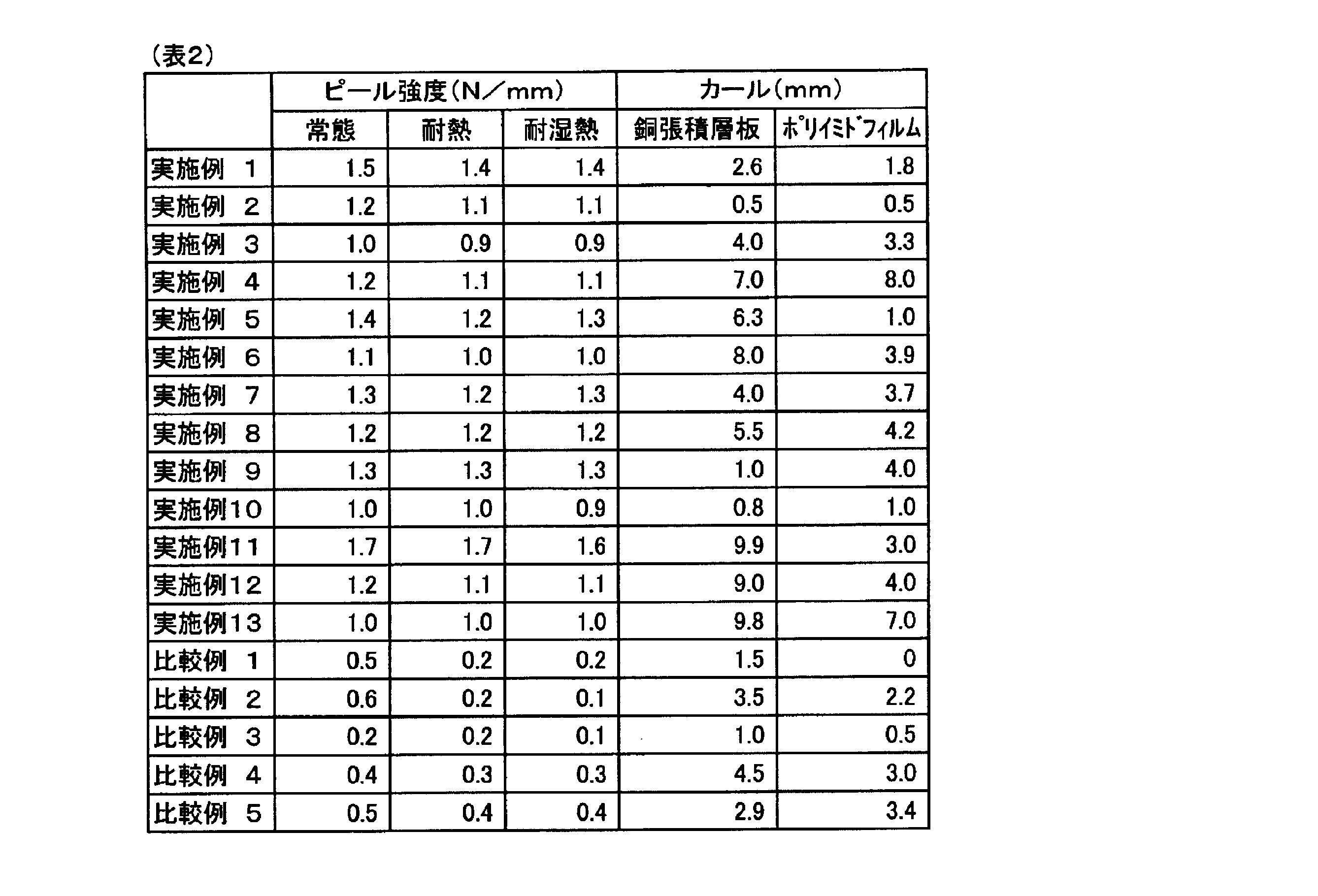
本発明の銅張積層板は、被覆層を有する粗化処理の施されていない銅箔と、被覆層に直接接着するポリイミドで構成されるため、それを用いて製造したプリント配線板の薄型化が可能な上、凹凸部分に食い込んだ樹脂がエッチング残渣として残らないため、より微細な配線パターンの形成が可能となる。さらに、配線表面の電気抵抗も小さくなり、特に高周波電流を用いる場合、表皮効果により銅箔表面の電流密度が高くなるため、プリント配線板の特性向上に優位に働く。
また、本発明の銅張積層板は、過酷な環境下においてもポリイミド樹脂層と銅箔との高い密着性が維持され、銅張積層板そのものとしてのカールが少ないのに加え、エッチングにより銅箔をすべて取り除きポリイミドフィルムのみにした場合におけるカールも少ないため、配線基板の材料として非常に実用的である。
また、本発明の銅張積層板は、過酷な環境下においてもポリイミド樹脂層と銅箔との高い密着性が維持され、銅張積層板そのものとしてのカールが少ないのに加え、エッチングにより銅箔をすべて取り除きポリイミドフィルムのみにした場合におけるカールも少ないため、配線基板の材料として非常に実用的である。
Claims (8)
- 被覆層を有する粗化処理を施されていない銅箔(A)と、該被覆層に直接接着するポリイミド(B)層で構成され、下記(1)~(4)の要件を満たす銅張積層板、
(1)該被覆層は銅箔表面から順に積層したNi層及びCr層で構成され、
(2)該被覆層におけるNi及びCrの被覆量がそれぞれ15~440μg/dm2及び15~210μg/dm2であり、
(3)該被覆層の厚さの最大値が0.5~5nm、かつ最小値が最大値の80%以上であり、
(4)ポリイミド(B)が、下記式(1)
(ただし、Arは芳香族四塩基酸残基を表し、Ar1は下記式(2)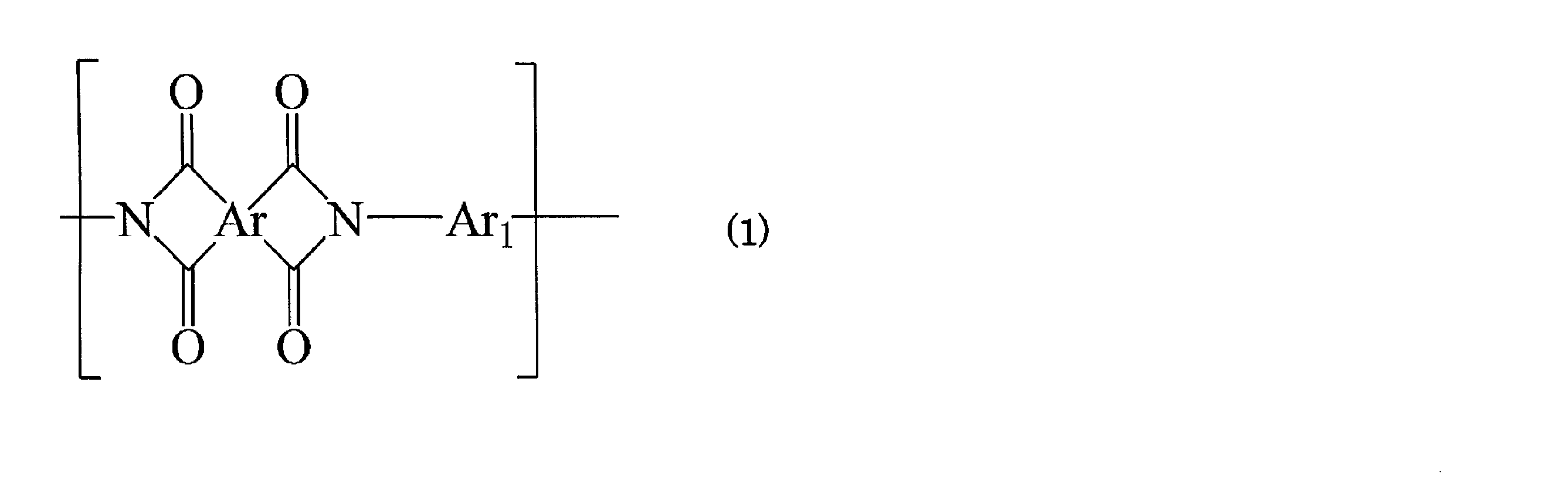
に記載の2種のジアミン残基より選ばれる少なくとも1種のジアミン残基を表す。)
で表される繰り返し単位を含むポリイミドである。 - ポリイミド(B)が、下記式(3)
(式(3)中Arは芳香族四塩基酸残基を表し、Ar2は、Ar1以外の芳香族ジアミン残基)
で表される繰り返し単位を含み、かつポリイミド(B)の全ジアミン残基の総量に対して、Ar1が5~30モル%、Ar2が70~95モル%である請求項1に記載の銅張積層板。 - Ar2がC1~C3アルキル基で置換されていてもよいフェニレン基、又は、フェニル基2個が単結合、又は、-CO-、-OCO-、C1-C3アルキレン、-NHCO-又は-NHCO-ph-CONH-からなる群から選ばれる2価の架橋基を介して結合したビスフェニレン基(フェニル基上に、ハロゲノ置換を有してもよいC1~C3のアルキル基又はC1~C3のアルコキシ基を置換基として有していてもよい)である請求項2に記載の銅張積層板。
- Ar2が下記式(4)
(式(4)中、R1及びR2はそれぞれ水素原子またはC1~C3のアルキル基を表し、R3はメチル基、エチル基、メトキシ基またはトリフルオロメチル基を表し、X2は酸素原子またはNH基を表す)
に記載のアミン残基よりなる群から選ばれる少なくとも1種のジアミン残基である請求項2又は3に記載の銅張積層板。 - Arが下記式(5)
に記載の芳香族四塩基酸残基なる群から選ばれる少なくとも1つの芳香族四塩基酸残基であり、かつ、ポリイミド(B)の全芳香族四塩基酸残基の総量に対して、該芳香族四塩基酸残基が70~100モル%である請求項1~4の何れか一項に記載の銅張積層板。
- 被覆層におけるNi層及びCr層がスパッタリングにより形成されたものである請求項1~5の何れか一項に記載の銅張積層板。
- 請求項1~6のいずれか一項に記載の銅張積層板を用いた配線基板。
- 粗化処理を施されていない銅箔の表面にNi層及びCr層の順にスパッタリングにより被覆層を形成し、被覆層を有する粗化処理を施されていない銅箔(A)を得、
次いで、該銅箔(A)の被覆層上に、下記(i)及び(ii)の成分、
(i)成分:芳香族四塩基酸及び/または芳香族四塩基酸ジアルキルエステル、
(ii)成分:式(1)のArで表される芳香族四塩基酸残基に対応する芳香族四塩基酸二無水物とAr1で表されるジアミン残基に対応するジアミンを含むジアミンとの反応で形成されたポリアミック酸、
を含むポリイミド前駆体(C)層を形成し、加熱処理によりポリイミド前駆体(C)層をイミド化させてポリイミド(B)層とする請求項1~6の何れか一項に記載の銅張積層板の製造方法。
Priority Applications (1)
| Application Number | Priority Date | Filing Date | Title |
|---|---|---|---|
| PCT/JP2012/002062 WO2013144991A1 (ja) | 2012-03-26 | 2012-03-26 | 銅張積層板及びその製造方法、並びに該銅張積層板を含む配線基板 |
Applications Claiming Priority (1)
| Application Number | Priority Date | Filing Date | Title |
|---|---|---|---|
| PCT/JP2012/002062 WO2013144991A1 (ja) | 2012-03-26 | 2012-03-26 | 銅張積層板及びその製造方法、並びに該銅張積層板を含む配線基板 |
Publications (1)
| Publication Number | Publication Date |
|---|---|
| WO2013144991A1 true WO2013144991A1 (ja) | 2013-10-03 |
Family
ID=49258367
Family Applications (1)
| Application Number | Title | Priority Date | Filing Date |
|---|---|---|---|
| PCT/JP2012/002062 Ceased WO2013144991A1 (ja) | 2012-03-26 | 2012-03-26 | 銅張積層板及びその製造方法、並びに該銅張積層板を含む配線基板 |
Country Status (1)
| Country | Link |
|---|---|
| WO (1) | WO2013144991A1 (ja) |
Cited By (1)
| Publication number | Priority date | Publication date | Assignee | Title |
|---|---|---|---|---|
| US10683259B2 (en) * | 2017-01-27 | 2020-06-16 | Wingo Technology Co., Ltd. | Diamine compound, and polyimide compound and molded product using the same |
Citations (3)
| Publication number | Priority date | Publication date | Assignee | Title |
|---|---|---|---|---|
| JP2005146074A (ja) * | 2003-11-13 | 2005-06-09 | Nippon Kayaku Co Ltd | ポリアミド酸、ポリアミド組成物及びポリイミド |
| JP2010239095A (ja) * | 2009-03-31 | 2010-10-21 | Nippon Mining & Metals Co Ltd | プリント配線板用銅箔 |
| JP2012076278A (ja) * | 2010-09-30 | 2012-04-19 | Nippon Kayaku Co Ltd | 銅張積層板及びその製造方法、並びに該銅張積層板を含む配線基板 |
-
2012
- 2012-03-26 WO PCT/JP2012/002062 patent/WO2013144991A1/ja not_active Ceased
Patent Citations (3)
| Publication number | Priority date | Publication date | Assignee | Title |
|---|---|---|---|---|
| JP2005146074A (ja) * | 2003-11-13 | 2005-06-09 | Nippon Kayaku Co Ltd | ポリアミド酸、ポリアミド組成物及びポリイミド |
| JP2010239095A (ja) * | 2009-03-31 | 2010-10-21 | Nippon Mining & Metals Co Ltd | プリント配線板用銅箔 |
| JP2012076278A (ja) * | 2010-09-30 | 2012-04-19 | Nippon Kayaku Co Ltd | 銅張積層板及びその製造方法、並びに該銅張積層板を含む配線基板 |
Cited By (3)
| Publication number | Priority date | Publication date | Assignee | Title |
|---|---|---|---|---|
| US10683259B2 (en) * | 2017-01-27 | 2020-06-16 | Wingo Technology Co., Ltd. | Diamine compound, and polyimide compound and molded product using the same |
| US11124474B2 (en) | 2017-01-27 | 2021-09-21 | Wingo Technology Co., Ltd. | Diamine compound, and polyimide compound and molded product using the same |
| US11136286B2 (en) | 2017-01-27 | 2021-10-05 | Wingo Technology Co., Ltd. | Diamine compound, and polyimide compound and molded product using the same |
Similar Documents
| Publication | Publication Date | Title |
|---|---|---|
| JP7382447B2 (ja) | 両面金属張積層板及び回路基板 | |
| TWI437937B (zh) | 銅配線聚醯亞胺膜之製造方法及銅配線聚醯亞胺膜 | |
| JP5345116B2 (ja) | 銅張積層板及びその製造方法、並びに該銅張積層板を含む配線基板 | |
| JP6767759B2 (ja) | ポリイミド、樹脂フィルム及び金属張積層板 | |
| JP5469578B2 (ja) | プライマー層を有する銅張積層板及びそれを用いた配線基板 | |
| JP4634439B2 (ja) | 金属積層板及びその製造方法 | |
| TW201525068A (zh) | 聚醯胺酸組合物、聚醯亞胺、樹脂膜及覆金屬積層體 | |
| KR20240049536A (ko) | 금속 피복 적층판, 접착 시트, 접착성 폴리이미드 수지 조성물 및 회로 기판 | |
| JP2019014062A (ja) | 積層体、フレキシブル金属張積層板、およびフレキシブルプリント回路基板 | |
| KR20210084275A (ko) | 금속 피복 적층판 및 회로 기판 | |
| TWI753196B (zh) | 覆金屬層疊板、黏接片、黏接性聚醯亞胺樹脂組合物及電路基板 | |
| CN107428146A (zh) | 聚酰亚胺层叠膜、聚酰亚胺层叠膜的制造方法、热塑性聚酰亚胺的制造方法、以及柔性金属包覆层叠体的制造方法 | |
| JP2006278371A (ja) | ポリイミド−金属層積層体の製造方法及びこの方法によって得たポリイミド−金属層積層体 | |
| WO2013144992A1 (ja) | プライマー層を有する銅張積層板及びそれを用いた配線基板 | |
| JP7195848B2 (ja) | ポリアミド酸、ポリイミド、樹脂フィルム、金属張積層体及びその製造方法 | |
| TWI282759B (en) | Electro-conductive metal plated polyimide substrate | |
| JP2020110972A (ja) | フィルム、金属張積層板、フレキシブル基板、フィルムの製造方法、金属張積層板の製造方法、及びフレキシブル基板の製造方法 | |
| JP2005135985A (ja) | プリント配線板の製造方法 | |
| JP4876396B2 (ja) | プリント配線板 | |
| TW201338970A (zh) | 具有底覆層之覆銅積層板及使用該積層板之配線基板 | |
| TWI654076B (zh) | 導體層之形成方法、及利用該形成方法的多層配線基板之製造方法 | |
| JP2020075483A (ja) | 金属張積層板の製造方法及び回路基板の製造方法 | |
| JP2019091934A (ja) | 回路基板 | |
| JP2019130876A (ja) | 金属張積層板及びその製造方法 | |
| JP2005329641A (ja) | フレキシブルプリント配線板用基板及びその製造方法 |
Legal Events
| Date | Code | Title | Description |
|---|---|---|---|
| 121 | Ep: the epo has been informed by wipo that ep was designated in this application |
Ref document number: 12872752 Country of ref document: EP Kind code of ref document: A1 |
|
| NENP | Non-entry into the national phase |
Ref country code: DE |
|
| 122 | Ep: pct application non-entry in european phase |
Ref document number: 12872752 Country of ref document: EP Kind code of ref document: A1 |
|
| NENP | Non-entry into the national phase |
Ref country code: JP |