WO2013141218A1 - Dispositif chirurgical de saisie - Google Patents
Dispositif chirurgical de saisie Download PDFInfo
- Publication number
- WO2013141218A1 WO2013141218A1 PCT/JP2013/057713 JP2013057713W WO2013141218A1 WO 2013141218 A1 WO2013141218 A1 WO 2013141218A1 JP 2013057713 W JP2013057713 W JP 2013057713W WO 2013141218 A1 WO2013141218 A1 WO 2013141218A1
- Authority
- WO
- WIPO (PCT)
- Prior art keywords
- probe
- jaw
- unit
- conductive portion
- electrode
- Prior art date
Links
Images


Classifications
-
- A—HUMAN NECESSITIES
- A61—MEDICAL OR VETERINARY SCIENCE; HYGIENE
- A61B—DIAGNOSIS; SURGERY; IDENTIFICATION
- A61B18/00—Surgical instruments, devices or methods for transferring non-mechanical forms of energy to or from the body
- A61B18/04—Surgical instruments, devices or methods for transferring non-mechanical forms of energy to or from the body by heating
- A61B18/12—Surgical instruments, devices or methods for transferring non-mechanical forms of energy to or from the body by heating by passing a current through the tissue to be heated, e.g. high-frequency current
- A61B18/14—Probes or electrodes therefor
- A61B18/1442—Probes having pivoting end effectors, e.g. forceps
- A61B18/1445—Probes having pivoting end effectors, e.g. forceps at the distal end of a shaft, e.g. forceps or scissors at the end of a rigid rod
-
- A—HUMAN NECESSITIES
- A61—MEDICAL OR VETERINARY SCIENCE; HYGIENE
- A61B—DIAGNOSIS; SURGERY; IDENTIFICATION
- A61B17/00—Surgical instruments, devices or methods, e.g. tourniquets
- A61B17/28—Surgical forceps
- A61B17/29—Forceps for use in minimally invasive surgery
- A61B2017/2926—Details of heads or jaws
- A61B2017/2927—Details of heads or jaws the angular position of the head being adjustable with respect to the shaft
- A61B2017/2929—Details of heads or jaws the angular position of the head being adjustable with respect to the shaft with a head rotatable about the longitudinal axis of the shaft
-
- A—HUMAN NECESSITIES
- A61—MEDICAL OR VETERINARY SCIENCE; HYGIENE
- A61B—DIAGNOSIS; SURGERY; IDENTIFICATION
- A61B17/00—Surgical instruments, devices or methods, e.g. tourniquets
- A61B17/32—Surgical cutting instruments
- A61B17/320068—Surgical cutting instruments using mechanical vibrations, e.g. ultrasonic
- A61B2017/320069—Surgical cutting instruments using mechanical vibrations, e.g. ultrasonic for ablating tissue
-
- A—HUMAN NECESSITIES
- A61—MEDICAL OR VETERINARY SCIENCE; HYGIENE
- A61B—DIAGNOSIS; SURGERY; IDENTIFICATION
- A61B17/00—Surgical instruments, devices or methods, e.g. tourniquets
- A61B17/32—Surgical cutting instruments
- A61B17/320068—Surgical cutting instruments using mechanical vibrations, e.g. ultrasonic
- A61B2017/320071—Surgical cutting instruments using mechanical vibrations, e.g. ultrasonic with articulating means for working tip
-
- A—HUMAN NECESSITIES
- A61—MEDICAL OR VETERINARY SCIENCE; HYGIENE
- A61B—DIAGNOSIS; SURGERY; IDENTIFICATION
- A61B17/00—Surgical instruments, devices or methods, e.g. tourniquets
- A61B17/32—Surgical cutting instruments
- A61B17/320068—Surgical cutting instruments using mechanical vibrations, e.g. ultrasonic
- A61B2017/320089—Surgical cutting instruments using mechanical vibrations, e.g. ultrasonic node location
-
- A—HUMAN NECESSITIES
- A61—MEDICAL OR VETERINARY SCIENCE; HYGIENE
- A61B—DIAGNOSIS; SURGERY; IDENTIFICATION
- A61B17/00—Surgical instruments, devices or methods, e.g. tourniquets
- A61B17/32—Surgical cutting instruments
- A61B17/320068—Surgical cutting instruments using mechanical vibrations, e.g. ultrasonic
- A61B17/320092—Surgical cutting instruments using mechanical vibrations, e.g. ultrasonic with additional movable means for clamping or cutting tissue, e.g. with a pivoting jaw
- A61B2017/320095—Surgical cutting instruments using mechanical vibrations, e.g. ultrasonic with additional movable means for clamping or cutting tissue, e.g. with a pivoting jaw with sealing or cauterizing means
-
- A—HUMAN NECESSITIES
- A61—MEDICAL OR VETERINARY SCIENCE; HYGIENE
- A61B—DIAGNOSIS; SURGERY; IDENTIFICATION
- A61B18/00—Surgical instruments, devices or methods for transferring non-mechanical forms of energy to or from the body
- A61B2018/00571—Surgical instruments, devices or methods for transferring non-mechanical forms of energy to or from the body for achieving a particular surgical effect
- A61B2018/00607—Coagulation and cutting with the same instrument
-
- A—HUMAN NECESSITIES
- A61—MEDICAL OR VETERINARY SCIENCE; HYGIENE
- A61B—DIAGNOSIS; SURGERY; IDENTIFICATION
- A61B18/00—Surgical instruments, devices or methods for transferring non-mechanical forms of energy to or from the body
- A61B2018/00994—Surgical instruments, devices or methods for transferring non-mechanical forms of energy to or from the body combining two or more different kinds of non-mechanical energy or combining one or more non-mechanical energies with ultrasound
Definitions
- the present invention grips an object to be grasped such as a living tissue between a distal end portion of the probe unit and a jaw that can be opened and closed with respect to the distal end portion of the probe unit, and performs treatment using ultrasonic vibration, high-frequency current, or the like.
- the present invention relates to a gripping treatment apparatus.
- Patent Document 1 Patent Document 2 and Patent Document 3 include a probe unit in which a first electrode portion (probe conductive portion) is provided at a tip portion, and a jaw that can be opened and closed with respect to the first electrode portion.
- a grasping treatment apparatus is disclosed.
- the probe unit includes a probe main body that transmits ultrasonic vibration from the proximal direction toward the distal direction, and the ultrasonic vibration is transmitted to the first electrode unit.
- a high frequency current is transmitted to the first electrode portion of the probe unit through the probe unit.
- the probe unit is inserted through the sheath body, and the probe unit and the sheath body are electrically insulated.
- a jaw is attached to the distal end of the sheath body.
- the jaw includes a contact portion that can contact the first electrode portion when the jaw is closed with respect to the first electrode portion, and a contact portion that is in contact with the first electrode portion.
- a second electrode portion having a clearance between the first electrode portion and the first electrode portion.
- the contact portion of the jaw is made of an insulating material.
- a high-frequency current is transmitted to the second electrode portion through the sheath body.
- the first treatment mode which is one treatment mode
- ultrasonic vibration is generated in the state where a biological tissue such as a blood vessel is gripped between the first electrode portion and the jaw (the tip portion of the probe unit).
- a high-frequency current is transmitted to the first electrode portion and the second electrode portion.
- the probe unit ultrasonically vibrates in a state where the living tissue to be grasped is gripped between the distal end portion of the probe unit and the jaw
- frictional heat is generated between the distal end portion of the probe unit and the biological tissue. Due to the generated frictional heat, incision and coagulation of the living tissue are simultaneously performed between the tip of the probe unit and the jaw.
- a high-frequency current flows through the living tissue grasped between the first electrode portion and the second electrode portion.
- the living tissue is reformed by the high-frequency current, and coagulation of the living tissue is promoted.
- the first electrode portion and the second electrode are in a state where a living tissue such as a blood vessel is held between the first electrode portion and the jaw. Only a high-frequency current is transmitted to the part.
- a high-frequency current flows through the living tissue grasped between the first electrode portion and the second electrode portion, and only the living tissue is coagulated.
- the present invention has been made paying attention to the above-mentioned problems, and the object of the present invention is to improve the coagulation property of the living tissue and stably seal the living tissue in the treatment mode not using ultrasonic vibration.
- An object of the present invention is to provide a grasping treatment device that can be stopped.
- a grasping treatment apparatus is a probe unit including a probe body that extends along a longitudinal axis and can transmit ultrasonic vibration from a proximal direction to a distal direction.
- the probe main body includes a probe unit having a probe conductive portion at a distal end, a sheath main body through which the probe unit is inserted, and a sheath unit electrically insulated from the probe unit; and the probe conductive A jaw that is attached to the distal end of the sheath body so as to be openable and closable with respect to a portion, formed of an insulating material, and capable of contacting the probe conductive portion with the jaw closed with respect to the probe conductive portion Jaw conduction having a clearance between the contact portion and the probe conductive portion in a state where the contact portion is in contact with the probe conductive portion.
- the first electrode portion having a first potential, and between the jaw and the first electrode portion in the opening and closing direction of the jaw, and at least one of the jaw conductive portions,
- at least the ultrasonic vibration is transmitted to the second electrode portion having a second potential different in magnitude from the first potential and the probe conductive portion.
- the first electrode part and the second electrode part From the first distance between the first electrode part and the second electrode part in one treatment mode, the first electrode part and the second electrode part have the high circumference Current only and a distance between electrodes changes units to reduce the second distance between the first electrode portion and the second electrode portion in the second treatment mode being transmitted.
- a grasping treatment apparatus capable of improving the coagulation property of a living tissue and stably sealing the living tissue in a treatment mode that does not use ultrasonic vibration.
- FIG. 3 is a cross-sectional view schematically showing the configuration of the vibrator unit according to the first embodiment.
- the side view which shows roughly the structure of the probe unit which concerns on 1st Embodiment.
- Sectional drawing which shows schematically the internal structure of the handle
- FIG. 5 is a sectional view taken along line VV in FIG. 4. Schematic which shows the electrical connection state in the vibrator
- FIG. 13 is a sectional view taken along line 13-13 in FIG. 7;
- FIG. 14 is a sectional view taken along line 14-14 of FIG.
- FIG. 15 is a sectional view taken along line 15-15 in FIG. 4;
- Sectional drawing which shows schematically the structure of the front-end
- Sectional drawing which shows schematically the internal structure of the rotary operation knob which concerns on the 2nd modification of 1st Embodiment in 1st treatment mode.
- Sectional drawing which shows schematically the internal structure of the rotary operation knob which concerns on the 2nd modification of 1st Embodiment in 2nd treatment mode.
- Sectional drawing which shows schematically the structure of the front-end
- Sectional drawing which shows schematically the structure of the front-end
- Sectional drawing which shows schematically the internal structure of the rotary operation knob which concerns on 2nd Embodiment in 1st treatment mode.
- Sectional drawing which shows schematically the internal structure of the rotary operation knob which concerns on 2nd Embodiment in 2nd treatment mode.
- Sectional drawing which shows schematically the structure of the front-end
- Sectional drawing which shows schematically the structure of the front-end
- Sectional drawing which shows schematically the structure of the front-end
- Sectional drawing which shows schematically the internal structure of the rotation operation knob which concerns on 3rd Embodiment in a 1st treatment mode and a relative rotation control state.
- Sectional drawing which shows schematically the internal structure of the rotary operation knob which concerns on 3rd Embodiment in a relative-rotatable state.
- FIG. 28 is a sectional view taken along line 28-28 in FIG.
- FIG. 29 is a sectional view taken along line 29-29 in FIG.
- Sectional drawing which shows schematically the connection state of the rotation operation knob which concerns on 3rd Embodiment, a sheath unit, and a connection cylindrical member in a 2nd treatment mode and a relative rotation control state.
- Sectional drawing which shows schematically the structure of the front-end
- Sectional drawing which shows schematically the structure of the front-end
- Schematic which shows the handle
- the side view which shows roughly the front-end
- FIG. 35 is a sectional view taken along line 35-35 in FIG. 34.
- FIG. 36 is a sectional view taken along line 36-36 in FIG. 34.
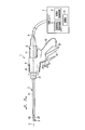
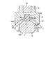
- FIG. 1 is a diagram illustrating a grasping treatment apparatus 1 according to the present embodiment.
- the grasping treatment device 1 has a longitudinal axis C.
- one of the two directions parallel to the longitudinal axis C is the distal direction (the direction of the arrow A1 in FIG. 1), and the direction opposite to the distal direction is the proximal direction (the direction of the arrow A2 in FIG. 1).
- a grasping treatment apparatus 1 that is a surgical operation apparatus includes a transducer unit 2, a probe unit 3, a handle unit 4, and a sheath unit 5.
- the vibrator unit 2 includes a vibrator case 11. One end of the cable 6 is connected to the base end of the vibrator case 11. The other end of the cable 6 is connected to the power supply unit 7.
- the power supply unit 7 includes an ultrasonic wave generation current supply unit 8, a high frequency current supply unit 9, and a control unit 10.
- the grasping treatment device 1 and the power supply unit 7 constitute a surgical operation system.
- FIG. 2 is a diagram showing the configuration of the vibrator unit 2.
- an ultrasonic transducer 12 including a piezoelectric element that converts current into ultrasonic vibration is provided inside the transducer case 11.
- One end of electric signal lines 13A and 13B is connected to the ultrasonic transducer 12.
- the electric signal lines 13 ⁇ / b> A and 13 ⁇ / b> B pass through the inside of the cable 6, and the other end is connected to the ultrasonic generation current supply unit 8 of the power supply unit 7.
- a columnar horn 15 that expands the amplitude of ultrasonic vibration is connected to the distal direction side of the ultrasonic transducer 12.
- the horn 15 is supported by the vibrator case 11 and is electrically insulated from the vibrator case 11.
- a female screw portion 16 is formed at the tip of the horn 15.
- an electrical signal line 17 extending from the high-frequency current supply unit 9 of the power supply unit 7 through the inside of the cable 6 is connected to the ultrasonic transducer 12. .
- FIG. 3 is a diagram showing the configuration of the probe unit 3.
- the probe unit includes a columnar probe main body 21 extending along the longitudinal axis C.
- the longitudinal axis C of the grasping treatment device 1 passes through the axis center of the probe main body 21.
- a male screw portion 22 is provided at a proximal end side portion of the probe main body 21.
- the probe main body 21 (probe unit 3) is attached to the horn 15 by the male screw portion 22 of the probe main body 21 screwing into the female screw portion 16 of the horn 15.
- the ultrasonic vibration generated by the ultrasonic vibrator 12 can be transmitted to the tip of the probe main body 21 (probe unit 3) via the horn 15. That is, the probe main body 21 can transmit ultrasonic vibration from the proximal direction to the distal direction.
- a probe conductive portion 23 is provided at the tip of the probe main body 21 (probe unit 3).
- the handle unit 4 includes a cylindrical case 31 that extends along the longitudinal axis C.
- the cylindrical case 31 is formed from an insulating material.
- a fixed handle 32 extends from the cylindrical case 31 in a direction inclined with respect to the longitudinal axis C.
- the fixed handle 32 is formed integrally with the cylindrical case 31.
- a movable handle 33 is rotatably attached to the cylindrical case 31.
- the movable handle 33 can be opened and closed substantially parallel to the longitudinal axis C with respect to the fixed handle 32.
- the movable handle 33 is located on the distal direction side with respect to the fixed handle 32.
- a stopper 35 is provided on the surface of the fixed handle 32 on the distal direction side. When the movable handle 33 comes into contact with the stopper 35, the movement of the movable handle 33 in the closing direction with respect to the fixed handle 32 is restricted.
- the vibrator unit 2 is connected to the cylindrical case 31 from the proximal direction side, and the sheath unit 5 is connected from the distal direction side. Further, the probe unit 3 is inserted into the cylindrical case 31 from the distal direction side.
- the sheath unit 5 includes a cylindrical sheath body 41 through which the probe unit 3 is inserted.
- a jaw 42 is rotatably attached to the distal end portion of the sheath body 41. The jaw 42 can be opened and closed with respect to the probe conductive portion 23 (first electrode portion 25) of the probe main body 21.
- the handle unit 4 includes a rotation operation knob 37 that is a rotation operation input unit connected to the distal direction side of the cylindrical case 31.
- the rotation operation knob 37 is connected to the cylindrical case 31 so as to be rotatable about the longitudinal axis.
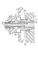
- FIG. 4 is a diagram showing an internal configuration of the handle unit 4.
- the probe main body 21 probe unit 3
- the sheath main body 41 sheath unit 5
- the probe main body 21 probe unit 3
- the sheath main body 41 sheath unit 5
- the probe main body 21 probe unit 3
- the sheath main body 41 sheath unit 5
- the proximal end of the probe body 21 is attached to the horn 15.
- the vibrator unit 2 and the probe unit 3 are connected.
- the base end portion of the sheath body 41 is connected to the transducer case 11.
- the vibrator unit 2 and the sheath unit 5 are connected.
- a connecting cylindrical member 45 that connects the probe main body 21 and the sheath main body 41 is provided.
- the sheath body 41 includes a movable tubular member 46 provided on the outer peripheral direction side of the connecting tubular member 45.
- the connecting cylindrical member 45 and the movable cylindrical member 46 are provided along the longitudinal axis C.
- the connecting cylindrical member 45 is formed from an insulating material such as resin.
- the movable cylindrical member 46 is made of a conductive material such as metal.
- FIG. 5 is a cross-sectional view taken along line VV in FIG.
- the engagement pins 47 ⁇ / b> A and 47 ⁇ / b> B are fixed to the rotary operation knob 37 in a state of being separated from each other in the direction around the longitudinal axis.
- the engagement pins 47A and 47B protrude from the inner peripheral portion of the rotation operation knob 37 in the inner peripheral direction.
- the movable cylindrical member 46 is provided with through holes 48A and 48B separated from each other in the direction around the longitudinal axis.
- Each through-hole 48A, 48B is formed in the shape of a long hole along the longitudinal axis C, and penetrates the movable cylindrical member 46 in the radial direction.
- the connecting tubular member 45 is provided with engaging recesses 49A and 49B that are recessed in the inner circumferential direction.
- the engaging recesses 49A and 49B are provided in a state separated from each other in the direction around the longitudinal axis.
- the engagement pin 47A is inserted through the through hole 48A and engaged with the engagement recess 49A.
- the engagement pin 47B is inserted through the through hole 48B and engaged with the engagement recess 49B.
- the connection cylindrical member 45 is fixed to the rotation operation knob 37 by the engagement pins 47A and 47B engaging with the corresponding engagement recesses 49A and 49B.
- the movable cylindrical member 46 and the rotation operation knob 37 cannot rotate about the longitudinal axis with respect to each other. Are regulated.
- the movable cylindrical member 46 moves along the longitudinal axis C with respect to the rotation operation knob 37 and the connecting cylindrical member 45. Is possible. With the configuration described above, the connecting cylindrical member 45 and the movable cylindrical member 46 can be rotated in the direction around the longitudinal axis with respect to the cylindrical case 31 integrally with the rotation operation knob 37. The movable cylindrical member 46 can move along the longitudinal axis C with respect to the probe main body 21 (probe unit 3) and the handle unit 4.
- An elastic member 51 formed of an insulating material is fixed to the outer peripheral portion of the base end portion of the probe main body 21 (see FIG. 3).
- the elastic member 51 is located at a node position of ultrasonic vibration.
- the elastic member 51 is pressed and contracted in the inner peripheral direction by the inner peripheral portion of the connecting cylindrical member 45.
- the probe main body 21 (probe unit 3) is fixed to the connection cylindrical member 45.
- the probe main body 21 (probe unit 3) and the sheath main body 41 (sheath unit 5) are connected by the connecting cylindrical member 45 and the elastic member 51.
- the rotary operation knob 37 When the rotary operation knob 37 is rotated in the direction around the longitudinal axis, the rotational driving force from the rotary operation knob 37 is transmitted to the probe main body 21 (probe unit 3) via the connecting cylindrical member 45 and the elastic member 51. Is done. Therefore, the probe unit 3 can be rotated with respect to the cylindrical case 31 integrally with the rotation operation knob 37 and the connecting cylindrical member 45. Further, since the connecting cylindrical member 45 and the elastic member 51 are formed of an insulating material, the probe main body 21 (probe unit 3) and the movable cylindrical member 46 are electrically insulated.
- the movable cylindrical member 46 is movable while being inserted into the vibrator case 11.
- the cylindrical member 46 and the vibrator case 11 are engaged.
- the rotation about the longitudinal axis with respect to each other is restricted.
- the movable cylindrical member 46 is movable along the longitudinal axis C with respect to the transducer case 11.
- an electrical connection ring 53 is provided on the outer peripheral direction side of the transducer case 11 at the connecting portion between the sheath body 41 and the transducer case 11.
- the electrical connection ring 53 is provided in a state of being fixed to the cylindrical case 31 of the handle unit 4. In a state where the transducer case 11 is coupled to the sheath body 41 (movable cylindrical member 46), the outer peripheral portion of the distal end portion of the transducer case 11 is in contact with the electrical connection ring 53, and the inner end portion of the transducer case 11 is inside. The peripheral portion is in contact with the movable cylindrical member 46.
- the transducer case 11 and the sheath body 41 can rotate integrally with respect to the electrical connection ring 53 in the direction around the longitudinal axis.
- a switch placement portion 55 is provided between the cylindrical case 31 and the fixed handle 32.
- the switch placement portion 55 is formed integrally with the cylindrical case 31 and the fixed handle 32.
- the switch placement portion 55 includes a flat portion 56 that is substantially perpendicular to the longitudinal axis C.
- the flat portion 56 is provided on the side where the fixed handle 32 and the movable handle 33 are located with the longitudinal axis C as the center. Further, the flat surface portion 56 is located on the distal direction side with respect to the movable handle 33.
- the plane portion 56 is provided with treatment mode input buttons 57A and 57B which are treatment mode input portions. By pressing each of the treatment mode input buttons 57A and 57B, an input operation for the treatment mode selected by the operator is performed.
- switch portions 58A and 58B and an electric circuit board 59 are provided inside the switch placement portion 55.
- the switch portion 58A is switched between open and closed states by an input operation using the treatment mode input button 57A.
- the open / close state of the switch unit 58B is switched by an input operation using the treatment mode input button 57B.
- FIG. 6 is a diagram schematically showing an electrical connection state in the vibrator case 11.
- three electric signal lines 61 ⁇ / b> A to 61 ⁇ / b> C are provided inside the cylindrical case 31.
- the electric signal line 61 ⁇ / b> A is electrically connected to the switch unit 58 ⁇ / b> A via an electric circuit on the electric circuit board 59.
- the electric signal line 61B is electrically connected to the switch unit 58B via an electric circuit on the electric circuit board 59.
- the electrical signal line 61C is electrically connected to the switch unit 58A and the switch unit 58B via an electrical circuit on the electrical circuit board 59.
- the electric signal line 61C is a common line shared as a ground line for the switch unit 58A and the switch unit 58B.
- the electrical connection ring 53 includes a first electrical connection portion 62A, a second electrical connection portion 62B, and a third electrical connection portion 62C. Between the first electrical connection portion 62A and the second electrical connection portion 62B, between the second electrical connection portion 62B and the third electrical connection portion 62C, and between the first electrical connection portion 62A and the third electrical connection portion 62B.
- the electrical connection portion 62C is electrically insulated.
- the electric signal line 61A is connected to the first electric connecting portion 62A.
- the electric signal line 61B is connected to the second electric connecting portion 62B.
- the electric signal line 61C is connected to the third electric connecting portion 62C.
- the vibrator case 11 includes a first conductive portion 63A, a second conductive portion 63B, and a third conductive portion 63C.
- the first conductive portion 63A, the second conductive portion 63B, and the third conductive portion 63C extend along the longitudinal axis C. Between the first conductive part 63A and the second conductive part 63B, between the second conductive part 63B and the third conductive part 63C, and between the first conductive part 63A and the third conductive part 63C Are electrically insulated.
- an electric signal line 65 is connected to the base end portion of the first conductive portion 63A.
- One end of an electric signal line 66 is connected to the base end portion of the second conductive portion 63B.
- One end of an electric signal line 67 is connected to the base end portion of the third conductive portion 63C.
- the electric signal lines 65 to 67 pass through the inside of the cable 6 and the other end is connected to the control unit 10 of the power supply unit 7.
- the first electric signal passes from the switch unit 58A to the control unit 10 of the power supply unit 7 through the electric signal line 61A, the first electric connection unit 62A, the first conductive unit 63A, and the electric signal line 65.
- a signal path is formed.
- a second electrical signal path passes from the switch unit 58B to the control unit 10 of the power supply unit 7 through the electrical signal line 61B, the second electrical connection unit 62B, the second conductive unit 63B, and the electrical signal line 66. Is formed.
- a ground path is formed from the switch unit 58A and the switch unit 58B to the control unit 10 through the electrical signal line 61C, the third electrical connection unit 62C, the third conductive unit 63C, and the electrical signal line 67. .
- the switch unit 58A By pressing the treatment mode input button 57A, the switch unit 58A is closed, and the first electrical signal path and the ground path are electrically connected by the switch unit 58A. Thereby, an electrical signal is transmitted from the switch unit 58 ⁇ / b> A to the control unit 10 of the power supply unit 7. Then, an ultrasonic generation current is output from the ultrasonic generation current supply unit 8 and a high frequency current is output from the high frequency current supply unit 9. That is, the first treatment mode is selected by pressing the treatment mode input button 57A.
- the switch unit 58B is closed, and the switch unit 58B is electrically connected between the second electrical signal path and the ground path.
- an electrical signal is transmitted from the switch unit 58 ⁇ / b> B to the control unit 10 of the power supply unit 7.
- a high frequency current is output from the high frequency current supply unit 9.
- no ultrasonic generation current is output from the ultrasonic generation current supply unit 8. That is, the second treatment mode different from the first treatment mode is selected by pressing the treatment mode input button 57B.
- the transducer case 11 includes a fourth conductive portion 63 ⁇ / b> D that extends along the longitudinal axis C.
- the first conductive portion 63A, the second conductive portion 63B, and the third conductive portion 63C are all electrically insulated from the fourth conductive portion 63D.
- An electric signal line 69 extending from the high frequency current supply part 9 of the power supply unit 7 through the inside of the cable 6 is connected to the base end part of the fourth conductive part 63D.
- the transducer case 11 is connected to the movable cylindrical member 46 (sheath body 41)
- only the distal end portion of the fourth conductive portion 63D is in electrical contact with the movable cylindrical member 46.
- the high-frequency current is transmitted between the high-frequency current supply unit 9 and the movable tubular member 46 of the sheath body 41 via the electric signal line 69 and the fourth conductive unit 63D.
- the sheath body 41 includes a fixed cylindrical member 71 located on the inner circumferential direction side of the rotation operation knob 37.
- the fixed cylindrical member 71 is fixed to the rotary operation knob 37 and is formed of an insulating material such as resin.
- a proximal end portion of the outer tube 72 and a proximal end portion of the outer pipe 73 are fixed to the distal end portion of the fixed cylindrical member 71.
- the outer tube 72 is positioned on the outer circumferential direction side from the outer pipe 73 and forms the outer sheath of the sheath body 41 (sheath unit 5).
- the outer tube 72 is made of an insulating material such as resin.
- An inner tube 75 is provided on the inner circumferential direction side from the outer pipe 73.
- the inner tube 75 is made of an insulating material such as resin and is fixed to the outer pipe 73 via fixing pins 76A and 76B. With the configuration as described above, the rotation operation knob 37 can be rotated around the longitudinal axis with respect to the cylindrical case 31 integrally with the outer tube 72, the outer pipe 73 and the inner tube 75.
- the sheath body 41 includes an inner pipe 77 provided between the outer pipe 73 and the inner tube 75 in the radial direction.
- the inner pipe 77 is fixed to the distal end portion of the movable cylindrical member 46 via a connection member 78 and a connection pin 79.
- the inner pipe 77 is movable along the longitudinal axis C with respect to the outer tube 72, the outer pipe 73 and the inner tube 75 integrally with the movable cylindrical member 46. That is, the inner pipe 77 is movable along the longitudinal axis C with respect to the handle unit 4 and the probe unit 3 integrally with the movable cylindrical member 46.
- the inner pipe 77 is fixed to the movable cylindrical member 46, the rotation operation by the rotation operation knob 37 is transmitted via the movable cylindrical member 46. Accordingly, the inner pipe 77 can rotate integrally with the rotation operation knob 37 in the direction around the longitudinal axis with respect to the cylindrical case 31. As described above, the rotation operation knob 37 can be rotated around the longitudinal axis with respect to the cylindrical case 31 integrally with the outer tube 72, the outer pipe 73 and the inner tube 75. Therefore, the sheath body 41 can rotate in the direction around the longitudinal axis with respect to the cylindrical case 31 integrally with the rotation operation knob 37.
- the inner pipe 77 is made of a conductive material such as metal. A high-frequency current is transmitted between the movable cylindrical member 46 and the inner pipe 77 via the connection member 78 and the connection pin 79.
- the sheath unit 5 includes a movable plate 81 that is a movable part provided along the longitudinal axis C on the inner circumferential direction side of the inner tube 75.
- the movable plate 81 is inserted into the sheath body 41 (inner tube 75) and is formed of a conductive material such as metal.
- the movable plate 81 is movable along the longitudinal axis C with respect to the probe main body 21 (probe unit 3) and the sheath main body 41.
- the movable plate 81 is fixed to a movement operation lever 83 that is a movement operation input unit via a relay unit 82 formed of a conductive material.
- the movement operation lever 83 is made of an insulating material.
- the movement operation lever 83 is connected to the rotation operation knob 37 so as to be movable along the longitudinal axis C.
- the movable plate 81 moves along the longitudinal axis C with respect to the probe main body 21 and the sheath main body 41. That is, an operation for moving the movable plate 81 that is a movable portion along the longitudinal axis C is input by the movement operation lever 83.
- the movement operation lever 83 and the rotation operation knob 37 are connected in a state in which they cannot rotate with respect to each other in the direction around the longitudinal axis. For this reason, the movement operation lever 83 and the movable plate 81 can rotate in the direction around the longitudinal axis with respect to the cylindrical case 31 together with the rotation operation knob 37.
- the sheath body 41 can rotate in the direction around the longitudinal axis with respect to the cylindrical case 31 together with the rotation operation knob 37. Therefore, the sheath unit 5 (the sheath main body 41 and the movable plate 81) can be rotated around the longitudinal axis with respect to the cylindrical case 31 integrally with the rotation operation knob 37.
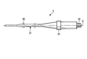
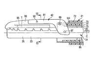
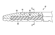
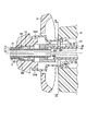
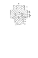
- FIGS. 7 and 8 are diagrams showing the tip of the probe unit 3, the tip of the sheath unit 5, and the jaw 42.
- FIG. 7 shows a state where the living tissue T is grasped and the treatment is performed in the first treatment mode
- FIG. 8 is a state where the living tissue T is grasped and the treatment is performed in the second treatment mode. Is shown.
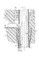
- the outer tube 72, the outer pipe 73, the inner tube 75, and the inner pipe 77 extend along the longitudinal axis C to the distal end portion of the sheath body 41 (sheath unit 5).
- a plurality of support members 85 made of an insulating material are formed on the outer peripheral portion of the probe main body 21. Each support member 85 is arranged away from the other support members 85 in the direction parallel to the longitudinal axis C. In a state where the probe main body 21 is connected to the horn 15, each support member 85 is located at a node position of ultrasonic vibration.
- the contact between the movable plate 81 and the probe main body 21 (probe unit 3) is prevented by the support member 85. Further, the support member 85 prevents contact between the inner tube 75 (sheath body 41) and the probe body 21 (probe unit 3).
- the connecting cylindrical member 45 and the elastic member 51 are formed of an insulating material, the probe main body 21 (probe unit 3) and the movable cylindrical member 46 (sheath main body 41) are electrically insulated. Has been. Therefore, the connection tubular member 45, the elastic member 51, and the support member 85 electrically insulate the sheath unit 5 (the sheath body 41 and the movable plate 81) and the probe unit 3 (the probe body 21).
- the jaw 42 is attached to the distal end portion of the sheath body 41 (the distal end portion of the outer tube 72 and the distal end portion of the outer pipe 73) via a connecting screw 87.
- the jaw 42 is rotatable with respect to the sheath body 41 around the connection screw 87.
- the tip of the inner pipe 77 is coupled to the jaw 42 via a connection pin 89.
- a high frequency current is transmitted between the inner pipe 77 and the jaw 42 via the connection pin 89.
- the high frequency current can be transmitted from the high frequency current supply unit 9 to the jaw 42 through the electric signal line 69, the fourth conductive portion 63 ⁇ / b> D, the movable cylindrical member 46, and the inner pipe 77.
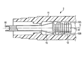
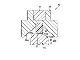
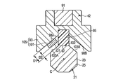
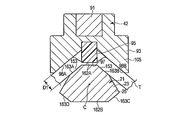
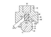
- 9 is a diagram showing the configuration of the jaw 42
- FIG. 10 is a cross-sectional view taken along the line XX of FIG.
- the probe main body 21 (probe conductive part 23) is also shown.
- the jaw 42 includes a jaw body 91 attached to the sheath body 41.
- the jaw body 91 is made of a conductive material.
- a jaw conductive portion 93 is coupled to the jaw body 91 via a connection pin 92.
- the high-frequency current transmitted from the inner pipe 77 of the sheath body 41 to the jaw 42 is transmitted to the jaw conductive portion 93 through the jaw body 91.
- the jaw conductive portion 93 has a second potential E2 having a magnitude different from that of the first potential E1.
- a pad member 95 that is an insulating contact member made of an insulating material is attached to the jaw conductive portion 93.
- the pad member 95 includes a jaw vertical facing surface (contact portion) 97 that is perpendicular to the opening / closing direction of the jaw 42. Further, in the width direction that is perpendicular to the longitudinal axis C and perpendicular to the opening and closing direction of the jaw 42, jaw inclined opposing surfaces 98A and 98B are formed on both sides of the jaw vertical opposing surface 97 by the jaw conductive portions 93. ing. In a cross section perpendicular to the longitudinal axis C, the jaw inclined facing surfaces 98A and 98B are inclined with respect to the jaw vertical facing surface 97.
- the probe conductive portion 23 (first electrode portion 25) includes a probe vertical facing surface 102 that is perpendicular to the opening / closing direction of the jaw 42.
- the probe vertical facing surface 102 is substantially parallel to the jaw vertical facing surface 97 and faces the jaw vertical facing surface 97.
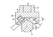
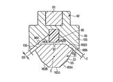
- there is no grasping target such as a blood vessel (living tissue) between the probe conductive portion 23 (first electrode portion 25) and the jaw 42, and the movement operation lever 83 is moved to the first operation position as will be described later.
- the jaw vertical facing surface 97 contacts the probe vertical facing surface 102 of the probe conductive portion 23. That is, when the jaw 42 is closed with respect to the probe conductive portion 23, the jaw vertical opposing surface (contact portion) 97 can contact the probe conductive portion 23.
- the probe is inclined by the probe conductive portion 23 (first electrode portion 25) in the width direction that is perpendicular to the longitudinal axis C and perpendicular to the opening / closing direction of the jaw 42.
- Opposing surfaces 103A and 103B are formed.
- the probe inclined facing surface 103A is substantially parallel to the jaw inclined facing surface 98A
- the probe inclined facing surface 103B is substantially parallel to the jaw inclined facing surface 98B.
- the probe inclined facing surface 103A and the jaw inclined facing surface 98A and the probe inclined facing surface 103B and the jaw inclined facing surface 98B are between.
- a clearance is always formed. That is, the jaw 42 is closed with respect to the probe conductive portion 23 in the state where there is no grasping target such as a blood vessel (biological tissue), and the jaw vertical facing surface (contact portion) 97 and the probe conductive portion 23 (probe vertical facing surface 102) Is in contact with the probe conductive portion 23 (the first electrode portion 25).
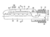
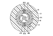
- FIG. 11 and 12 are diagrams showing the internal configuration of the rotary operation knob 37.
- FIG. FIG. 11 shows the first treatment mode
- FIG. 12 shows the second treatment mode
- 13 is a sectional view taken along line 13-13 in FIG. 7
- FIG. 14 is a sectional view taken along line 14-14 in FIG.
- the movement operation lever 83 is located at the first operation position.
- the movable plate 81 and the relay portion 82 do not contact the inner pipe 77. Therefore, the movable plate 81 and the inner pipe 77 are electrically insulated, and no high frequency current is transmitted to the movable plate 81.
- a moving conductive portion 101 is provided at the tip of the movable plate 81.
- the moving conductive portion 101 is housed inside the sheath body 41 as shown in FIG. 7 by the operation of the movement operation lever 83 moving to the first operation position. That is, the movable conductive portion 101 is located on the proximal direction side with respect to the jaw 42.
- an ultrasonic wave generation current is output from the ultrasonic wave generation current supply unit 8. For this reason, ultrasonic vibration is generated in the ultrasonic vibrator 12, and the ultrasonic vibration is transmitted to the probe conductive portion 23 (the tip portion of the probe unit 3).
- a high frequency current is output from the high frequency current supply unit 9. For this reason, the high-frequency current is transmitted to the probe conductive portion 23, and the probe conductive portion 23 becomes the first electrode portion 25 having the first potential E1. Further, the high frequency current is transmitted to the jaw conductive portion 93 of the jaw 42, and the jaw conductive portion 93 has the second potential E2. At this time, since the high frequency current is not transmitted to the movable plate 81, the movable conductive portion 101 does not function as an electrode.
- the jaw conductive portion 93 functions as the second electrode portion 105 having the second potential E2.
- the first electrode portion 25 probe inclined facing surfaces 103A and 103B
- the jaw conductive portion 93 jaw inclined facing surface 98A, 98B
- the movement operation lever 83 is moved from the first operation position to the distal direction side and is located at the second operation position.
- the relay portion 82 is in contact with the inner pipe 77. Therefore, the movable plate 81 and the inner pipe 77 are electrically connected, and a high frequency current is transmitted to the movable plate 81.
- the movable conductive portion 101 has the second potential E2.
- the movement conductive portion 101 moves the jaw vertical facing surface 97 (in the opening / closing direction of the jaw 42) by the operation of moving the movement operation lever 83 to the second operation position. It is located between the jaw 42) and the probe vertical facing surface 102 (first electrode portion 25).
- the movable conductive portion 101 includes a movable portion facing surface 106 that is perpendicular to the opening / closing direction of the jaw 42.
- the movable part facing surface 106 is substantially parallel to the probe vertical facing surface 102 and faces the probe vertical facing surface 102.
- the distance between the movable portion facing surface 106 (moving conductive portion 101) and the probe vertical facing surface 102 (first electrode portion 25) in a state where the living tissue T is gripped is smaller than the first distance D1.
- the jaw conductive portion 93 and the movable conductive portion 101 function as the second electrode portion 105 having the second potential E2, and the movable conductive portion 101 is a part of the second electrode portion 105. It becomes. Therefore, in the second treatment mode, the moving conductive portion 101 (movable portion facing surface 106) of the first electrode portion 25 (probe vertical facing surface 102) and the second electrode portion 105 with the living tissue T gripped. ) Is a second distance D2 that is smaller than the first distance D1. That is, in the second treatment mode, the living tissue T can be subjected to the high frequency treatment in a state where the second distance D2 is smaller than the first distance D1.
- the movement operation lever (movement operation input unit) 83 is set to the second distance from the first distance D1 between the first electrode unit 25 and the second electrode unit 105 in the first treatment mode.
- This is an interelectrode distance changing unit that reduces the second distance D2 between the first electrode portion 25 and the second electrode portion 105 in the treatment mode. That is, the distance between the two electrode parts (the first electrode part 25 and the second electrode part 105) is changed by the movement operation lever 83.
- ultrasonic vibration is not transmitted to the probe conductive portion 23 (tip portion of the probe unit 3), and only high-frequency current is transmitted to the first electrode portion 25 and the second electrode portion 105.
- sufficient high-frequency treatment for example, coagulation
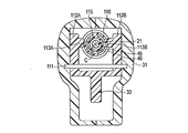
- the movable handle 33 is attached to the cylindrical case 31 via a fulcrum pin 111.
- the movable handle 33 rotates with respect to the cylindrical case 31 around the fulcrum pin 111.
- the movable handle 33 includes arm portions 112A and 112B.
- the arm portion 112A is provided with an engaging protrusion 113A that protrudes in the inner peripheral direction
- the arm portion 112B is provided with an engaging protrusion 113B that protrudes in the inner peripheral direction.
- a slide member 115 is disposed on the outer peripheral side of the movable cylindrical member 46.
- the slide member 115 is formed with an engagement groove 116 that is recessed in the inner circumferential direction along the direction around the longitudinal axis.
- the engagement protrusions 113 ⁇ / b> A and 113 ⁇ / b> B are engaged with the engagement groove 116, the movable handle 33 is attached to the slide member 115.
- the slide member 115 can rotate about the longitudinal axis with respect to the movable handle 33 and the cylindrical case 31 integrally with the movable cylindrical member 46 (sheath body 41).
- the slide member 115 is made of an insulating material. Therefore, the movable tubular member 46 (sheath body 41) and the movable handle 33 are electrically insulated.
- a coil spring 117 and a stopper 118 which are elastic members, are provided on the outer peripheral side of the movable cylindrical member 46.
- One end of the coil spring 117 is connected to the tip of the slide member 115, and the other end is connected to the movable cylindrical member 46.
- the length of the coil spring 117 in the natural state is L0.
- the elastic force k0x0 acts on the movable cylindrical member 46 from the coil spring 117 with the elastic coefficient of the coil spring 117 as k0.
- the stopper 118 restricts the movement of the slide member 115 in the proximal direction.
- the movable handle 33 When the object to be grasped is grasped between the probe conductive part 23 (first electrode part 25) and the jaw 42 in the first treatment mode, or in the second treatment mode, the probe conductive part 23 (first electrode part) 25) and the movable conductive part 101, when the object to be grasped is grasped, the movable handle 33 is closed with respect to the fixed handle 32. As a result, the movable handle 33 rotates about the fulcrum pin 111, and the slide member 115, the movable cylindrical member 46, and the inner pipe 77 move together along the longitudinal axis C in the distal direction.
- the coil spring 117 does not contract from the reference state, and the elastic force acting on the movable cylindrical member 46 from the coil spring 117 does not change from k0x0.
- the jaw 42 performs a closing operation on the probe conductive portion 23.
- the jaw 42 When the jaw 42 comes into contact with the grasped object such as the living tissue T in the first treatment mode, or when the jaw 42 comes into contact with the moving conductive portion 101 in the second treatment mode, the jaw 42 is closed. Temporarily stops. For this reason, the movement of the movable tubular member 46 and the inner pipe 77 in the distal direction is temporarily stopped. When the movable handle 33 is further closed with respect to the fixed handle 32 in this state, the slide member 115 moves in the distal direction with respect to the movable cylindrical member 46.
- the movement of the slide member 115 relative to the movable cylindrical member 46 causes the coil spring 117 to further contract from the reference state.
- the displacement amount (shrinkage amount) of the coil spring 117 from the reference state is x
- the elastic force that acts on the movable cylindrical member 46 from the coil spring 117 when the coil spring 117 further contracts from the reference state is k0 (x0 + x). It becomes larger than the elastic force k0x0 in the reference state.
- the elastic force k0 (x0 + x) larger than the elastic force k0x0 in the reference state acts on the movable cylindrical member 46 from the coil spring 117, the temporarily stopped movable cylindrical member 46 and the inner pipe 77 move further in the distal direction. To do.
- the jaw 42 in contact with the object to be grasped or the moving conductive portion 101 is further closed with respect to the probe conductive portion 23. Therefore, as compared with the case where the coil spring 117 is in the reference state, it is between the jaw 42 and the probe conductive portion 23 (first electrode portion 25) or between the moving conductive portion 101 and the probe conductive portion 23 (first electrode portion). 25), the gripping force for gripping the gripping object increases.
- the operation of the grasping treatment device 1 of the present embodiment will be described.
- the operator moves the movement operation lever 83, which is a movement operation input unit, to the first operation position.
- the movable conductive portion 101 is housed inside the sheath body 41 and is located on the proximal direction side from the jaw 42.
- the movable handle 33 is closed with respect to the fixed handle 32.
- the jaw 42 performs a closing operation on the probe conductive portion 23 of the probe main body 21 (probe unit 3) according to the above-described principle, and between the jaw 42 and the probe conductive portion 23 (first electrode portion 25).
- an object to be grasped such as a blood vessel.
- the switch unit 58A electrically connects the first electrical signal path and the ground path, and an electrical signal is transmitted from the switch unit 58A to the control unit 10 of the power supply unit 7.
- an ultrasonic generation current is output from the ultrasonic generation current supply unit 8 and a high frequency current is output from the high frequency current supply unit 9.
- the high-frequency current output from the high-frequency current supply unit 9 is transmitted to the probe conductive unit 23 through the electric signal line 17, the ultrasonic transducer 12, the horn 15, and the probe body 21 (probe unit 3).
- the probe conductive portion 23 functions as the first electrode portion 25 having the first potential E1.
- the high frequency current is transmitted from the high frequency current supply unit 9 to the jaw conductive unit 93 through the electric signal line 69, the fourth conductive unit 63 ⁇ / b> D, the movable tubular member 46, the inner pipe 77 and the jaw 42.
- the jaw conductive portion 93 has a second potential E2 having a magnitude different from that of the first potential E1.
- the movement operation lever 83 is located at the first operation position, the movable plate 81 and the movable cylindrical member 46 are electrically insulated. For this reason, the high frequency current is not transmitted to the movable plate 81, and the movable conductive portion 101 does not function as an electrode. Therefore, in the first treatment mode, only the jaw conductive portion 93 functions as the second electrode portion 105 having the second potential E2.
- the probe conductive portion 23 (first electrode portion 25) has the first potential E1 and the jaw conductive portion 93 (second electrode portion 105) has the second potential E2, the probe conductive portion 23 and the jaw A high-frequency current flows through the object to be grasped between 42 and 42. As a result, the object to be grasped such as the living tissue T is transformed, and coagulation is promoted.
- the moving conductive portion 101 is located on the proximal direction side with respect to the jaw 42, so that the probe conductive portion 23 (probe inclined facing surfaces 103 ⁇ / b> A and 103 ⁇ / b> B) of the first electrode portion 25 and the second electrode portion 105.
- the distance between the jaw conductive portion 93 (the jaw inclined facing surfaces 98A and 98B) is the first distance D1.
- the first distance D1 is such that the first electrode portion 25 and the second electrode portion 105 (jaw conductive portion 93) are in contact with each other even when the probe main body 21 (probe unit 3) is ultrasonically vibrated. Have no distance. Thereby, failure of the grasping treatment device 1 due to a short circuit (short circuit) is effectively prevented.
- the probe body 21 is ultrasonically vibrated. For this reason, the pad member 95 that can contact the probe conductive portion 23 with the jaw 42 closed with respect to the probe conductive portion 23 is worn by the treatment in the first treatment mode. Therefore, the first distance D1 is set so that the probe conductive portion 23 (first electrode portion 25) and the jaw from the start of use of the grasping treatment device 1 even when the pad member 95 is slightly worn by the treatment in the first treatment mode.
- the conductive portion 93 (second electrode portion 105) has a distance that does not contact.
- the operator moves the movement operation lever 83, which is a movement operation input unit, to the second operation position. Accordingly, the movable conductive portion 101 is positioned between the jaw vertical facing surface 97 (the jaw 42) and the probe vertical facing surface 102 (the first electrode portion 25) in the opening / closing direction of the jaw 42.
- the movable handle 33 is closed with respect to the fixed handle 32. Accordingly, the jaw 42 performs a closing operation on the probe conductive portion 23 of the probe main body 21 (probe unit 3) based on the above-described principle, and the moving conductive portion 101 and the probe conductive portion 23 (first electrode portion 25) Grasping a grasped object such as a blood vessel between At this time, when the jaw 42 comes into contact with the moving conductive portion 101, the moving conductive portion 101 is pressed by the jaw 42 in the closing direction of the jaw 42. As a result, the gripping target is sandwiched between the probe conductive portion 23 (first electrode portion 25) and the movable conductive portion 101, and the gripping target is gripped.
- the high-frequency current output from the high-frequency current supply unit 9 is transmitted to the probe conductive unit 23 through the electric signal line 17, the ultrasonic transducer 12, the horn 15, and the probe main body 21 (probe unit 3).
- the probe conductive portion 23 functions as the first electrode portion 25 having the first potential E1.
- the high frequency current is transmitted from the high frequency current supply unit 9 to the jaw conductive unit 93 through the electric signal line 69, the fourth conductive unit 63 ⁇ / b> D, the movable tubular member 46, the inner pipe 77 and the jaw 42.
- the jaw conductive portion 93 has a second potential E2 having a magnitude different from that of the first potential E1.
- the movable plate 81 and the inner pipe 77 are electrically connected. For this reason, a high frequency current is transmitted to the movable plate 81, and the movable conductive portion 101 functions as the second electrode portion 105 having the second potential E2. Therefore, in the second treatment mode, the jaw conductive portion 93 and the movable conductive portion 101 function as the second electrode portion 105 having the second potential E2, and the movable conductive portion 101 is a part of the second electrode portion 105. It becomes. Further, in the second treatment mode, ultrasonic vibration is not transmitted to the probe conductive portion 23 (tip portion of the probe unit 3), and only high-frequency current is transmitted to the first electrode portion 25 and the second electrode portion 105.
- the probe A high-frequency current also flows through the object to be gripped between the conductive portion 23 and the movable conductive portion 101. Thereby, grasping objects, such as living tissue T, are changed and coagulation is performed.
- the probe conductive portion 23 ( The distance between the probe vertical facing surface 102) and the movable conductive portion 101 (movable portion facing surface 106) of the second electrode portion 105 is the second distance D2.
- the second distance D2 is smaller than the first distance D1. That is, the distance between the first electrode unit 25 and the second electrode unit 105 is smaller in the second treatment mode than in the first treatment mode. Since the distance between the first electrode unit 25 and the second electrode unit 105 is reduced, the living tissue T (gripping target) is transformed by the high-frequency current in the second treatment mode compared to the first treatment mode. Promoted.
- the coagulation performance of the object to be grasped by the high-frequency current is improved, a decrease in the coagulation performance of the object to be grasped is prevented even in the second treatment mode that does not use ultrasonic vibration.
- the grasp object living tissue is stably sealed.
- the movable conductive portion 101 is positioned between the jaw vertical facing surface (contact portion) 97 and the probe vertical facing surface 102 in the opening / closing direction of the jaw 42. Then, the object to be gripped is gripped between the moving conductive portion 101 and the probe conductive portion 23 (first electrode portion 25).
- the probe vertical facing surface 102 of the probe conductive portion 23 is perpendicular to the opening / closing direction of the jaw 42.
- the movable portion facing surface 106 of the moving conductive portion 101 is substantially parallel to the probe vertical facing surface 102 and faces the probe vertical facing surface 102.
- the gripping force increases.
- the solidification performance of the object to be gripped by the high-frequency current is further improved. Thereby, a grasp object (living tissue) is sealed more stably.
- the gripping treatment apparatus 1 having the above configuration has the following effects.
- the movable conductive portion 101 in the grasping treatment apparatus 1, in the second treatment mode, the movable conductive portion 101 is positioned between the jaw 42 and the probe conductive portion 23 (first electrode portion 25) in the opening / closing direction of the jaw 42. Therefore, the distance between the probe conductive portion 23 (probe vertical facing surface 102) of the first electrode portion 25 and the moving conductive portion 101 (movable portion facing surface 106) of the second electrode portion 105 is equal to the second Distance D2.
- the second distance D2 is smaller than the first distance D1. That is, the distance between the first electrode unit 25 and the second electrode unit 105 is smaller in the second treatment mode than in the first treatment mode.
- the living tissue T is transformed by the high-frequency current in the second treatment mode compared to the first treatment mode. Promoted. Therefore, since the coagulation performance of the object to be grasped by the high-frequency current is improved, it is possible to prevent the coagulation performance of the object to be grasped from being lowered even in the second treatment mode that does not use ultrasonic vibration. Thereby, also in the 2nd treatment mode which does not use ultrasonic vibration, a grasp object (living tissue) can be sealed stably.
- the movable conductive portion 101 is located between the jaw vertical facing surface (contact portion) 97 and the probe vertical facing surface 102 in the second treatment mode between the jaw vertical facing surface (contact portion) 97 and the moving direction.
- the movable portion facing surface 106 of the conductive portion 101 is perpendicular to the opening / closing direction of the jaw 42, but is not limited thereto.
- the movable conductive portion 101 in the second treatment mode, is provided between the jaw inclined facing surface 98A and the probe inclined facing surface 103A in the opening / closing direction of the jaw 42. May be.
- the living tissue T gripped between the jaw 42 and the probe main body 21 (probe conductive portion 23) is not shown.
- the movable conductive portion 101 includes a movable portion facing surface 121 substantially parallel to the jaw inclined facing surface 98A and the probe inclined facing surface 103A.
- the movable part facing surface 121 is not perpendicular to the opening and closing direction of the jaw 42, but faces the probe inclined facing surface 103A in the second treatment mode.
- the movable conductive portion 101 is located on the proximal direction side from the jaw 42 in the first treatment mode. Therefore, the distance between the probe inclined facing surface 103A and the jaw inclined facing surface 98A (the distance between the probe inclined facing surface 103B and the jaw inclined facing surface 98B) is the first electrode in the first treatment mode. This is the first distance D1 between the portion 25 (the probe conductive portion 23) and the second electrode portion 105 (the jaw conductive portion 93). In the second treatment mode, the movable conductive portion 101 is positioned between the jaw inclined facing surface 98A and the probe inclined facing surface 103A in the opening / closing direction of the jaw 42.
- the distance between the movable portion facing surface 121 and the probe inclined facing surface 103A is such that the first electrode portion 25 (probe conductive portion 23) and the second electrode portion 105 (moving conductive state) in the second treatment mode. Part 101).
- the distance between the first electrode unit 25 and the second electrode unit 105 is smaller in the second treatment mode than in the first treatment mode. Since the distance between the first electrode unit 25 and the second electrode unit 105 is reduced, the living tissue T (gripping target) is transformed by the high-frequency current in the second treatment mode compared to the first treatment mode. Promoted.
- the movable plate 81 is moved by the operation of moving the movement operation lever 83 along the longitudinal axis C between the first operation position and the second operation position.
- a movement operation button 122 may be provided as a movement operation input unit.
- the movement operation button 122 is made of an insulating material, and is attached to the rotation operation knob 37 in a state in which rotation around the longitudinal axis with respect to the rotation operation knob 37 is restricted.
- a relay portion 123 made of a conductive material is provided integrally with the movement operation button 122 on the inner circumferential direction side of the movement operation button 122.
- a movable plate (movable part) 81 is provided between the inner tube 75 and the probe main body 21 (probe unit 3).
- the movable plate 81 is provided so as to be movable along the longitudinal axis C with respect to the probe main body 21 and the sheath main body 41.
- the movable plate 81 and the probe main body 21 are electrically insulated by a support member 85.
- the relay portion 123 is provided with a button side inclined surface 125A.
- a plate-side inclined surface 125B parallel to the button-side inclined surface 125A is provided at the base end portion of the movable plate 81.
- a protrusion 127 that is formed of an insulating material and protrudes in the inner peripheral direction is provided on the inner peripheral portion of the rotation operation knob 37.
- the protrusion 127 is located on the proximal direction side from the proximal end of the movable plate 81.
- a spring member 128 that is an urging member is provided between the protruding portion 127 and the movable plate 81.
- the spring member 128 has one end connected to the base end of the movable plate 81 and the other end connected to the protrusion 127.
- the movable plate 81 is biased in the proximal direction by the spring member 128.
- the movement operation button 122 is not pressed by the operator, and the movement operation button 122 is positioned at the first operation position.
- the button side inclined surface 125 ⁇ / b> A of the relay portion 123 and the plate side inclined surface 125 ⁇ / b> B of the movable plate 81 are not in contact with each other or are partially in contact with each other. For this reason, the movable plate 81 is not pressed by the relay portion 123.
- the movable plate 81 is biased in the proximal direction by the spring member 128. Therefore, the movable conductive portion 101 provided at the distal end portion of the movable plate 81 is accommodated in the sheath body 41 and is located on the proximal direction side from the jaw 42.
- the movement operation button 122 moves from the first operation position to the second operation position. .
- the button side inclined surface 127A of the relay part 123 and the plate side inclined surface 127B of the movable plate 81 abut.
- the movable plate 81 is pressed in the distal direction by the relay portion 123.
- the movable plate 81 moves in the distal direction against the urging force from the spring member 128. Therefore, the movable conductive portion 101 provided at the tip of the movable plate 81 is located between the jaw 42 and the probe conductive portion 23 (first electrode portion 25) in the opening / closing direction of the jaw 42.
- the distance between the first electrode unit 25 and the second electrode unit 105 in the second treatment mode is compared with the first treatment mode from the first modification example and the second modification example.
- the configuration to be reduced is not limited to the first embodiment. That is, the movable part (movable plate 81) is provided in a state of being inserted into the sheath body 41, and the movable part (movable plate 81) can move along the longitudinal axis C with respect to the probe body 21 and the sheath body 41. If it is.
- the moving conductive portion 101 is provided at the tip of the movable portion (movable plate 81), and the movement operation input portion (the movement operation lever 83 or the movement operation button 122) to which an operation for moving the movable portion is input is provided.
- the moving conductive portion 101 is positioned closer to the proximal direction side than the jaw 42 in the first treatment mode by an operation at the moving operation input portion. Further, by the operation at the moving operation input unit, the moving conductive unit 101 is positioned between the jaw 42 and the first electrode unit 25 in the opening / closing direction of the jaw 42 in the second treatment mode. In the second treatment mode, the movable conductive portion 101 functions as at least a part of the second electrode portion 105 by transmitting a high-frequency current through the movable portion (movable plate 81).
- FIGS. 19 and 20 are diagrams showing the configuration of the tip of the probe unit 3 and the jaw 42.
- FIG. FIG. 19 shows a state where the living tissue T is grasped and treated in the first treatment mode
- FIG. 20 shows a state where the living tissue T is grasped and treated in the second treatment mode.
- a probe conductive portion 23 is provided at the distal end portion of the probe main body 21 of the probe unit 3 as in the first embodiment.
- the probe unit 3 inserted through the sheath body 41 includes a movable plate 131 that is a movable portion provided along the longitudinal axis C on the inner circumferential direction side of the inner tube 75.
- the movable plate 131 is made of a conductive material such as metal. The movable plate 131 is movable along the longitudinal axis C with respect to the probe main body 21 and the sheath main body 41 (sheath unit 5).
- the movable plate 131 and the sheath body 41 are electrically insulated by an inner tube 75. Further, the probe main body 21 and the sheath main body 41 are electrically insulated by the support member 85 and the inner tube 75. Therefore, the probe unit 3 and the sheath unit 5 are electrically insulated.
- the movable plate 131 is fixed to a movement operation button 133 that is a movement operation input unit via a relay unit 132 formed of a conductive material.
- the movement operation button 133 is made of an insulating material.
- the movement operation button 133 is connected to the rotation operation knob 37 in a state where the rotation around the longitudinal axis with respect to the rotation operation knob 37 is restricted.
- an insulating coating process is performed on a part of the surface of the relay portion 132 to form an insulating layer portion 135.
- the relay portion 132 is provided with a plate-side inclined surface 137A.
- a sheath-side inclined surface 137B parallel to the plate-side inclined surface 137A is provided at the proximal end portion of the inner tube 75 of the sheath body 41.
- the inner periphery of the rotary operation knob 37 is provided with a protrusion 138 made of an insulating material and protruding in the inner peripheral direction.
- the protruding portion 138 is located on the proximal direction side of the relay portion 132.
- a spring member 139 that is an urging member is provided between the protruding portion 138 and the relay portion 132.
- the spring member 139 has one end connected to the insulating layer part 135 and the other end connected to the protrusion 138.
- the relay part 132 and the movable plate 131 are biased in the proximal direction by the spring member 139.
- the movable plate 131 moves along the longitudinal axis C with respect to the probe main body 21 and the sheath main body 41 by the operation with the movement operation button 133. That is, an operation for moving the movable plate 131 as a movable portion along the longitudinal axis C is input by the movement operation button 133.
- the movement operation button 133 is not pressed by the surgeon, and the movement operation button 133 is located at the first operation position.
- the plate-side inclined surface 137A of the relay portion 132 and the sheath-side inclined surface 137B of the inner tube 75 are in contact with each other.
- the movable plate 131 is biased in the proximal direction by the spring member 129.
- a movable conductive portion 141 is provided at the tip of the movable plate 131.
- the movable plate 131 is biased in the proximal direction, so that the movement conductive portion 141 is housed inside the sheath body 41. . That is, the movable conductive portion 141 is located on the proximal direction side with respect to the jaw 42 (see FIG. 19).
- the movable plate 131 and the relay unit 132 do not contact the probe main body 21. Therefore, the movable plate 131 and the probe main body 21 are electrically insulated, and no high frequency current is transmitted from the probe main body 21 to the movable plate 131.
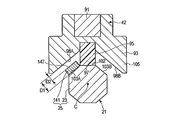
- the probe conductive portion 23 includes a probe vertical facing surface 102 and probe inclined facing surfaces 103A and 103B, as in the first embodiment. Similar to the first embodiment, when the high-frequency current is transmitted, the probe conductive portion 23 functions as the first electrode portion 25 having the first potential E1.
- the jaw 42 is formed with a jaw vertical facing surface 142 parallel to the probe vertical facing surface 102 by the jaw conductive portion 93.
- the probe vertical facing surface 102 faces the jaw vertical facing surface 142 in the first treatment mode.
- a first jaw inclined opposing surface 143A is formed by a pad member 95 on one side of the jaw vertical opposing surface 142 in the width direction that is perpendicular to the longitudinal axis C and perpendicular to the opening and closing direction of the jaw 42.
- a second jaw inclined facing surface 143 ⁇ / b> B is formed by the jaw conductive portion 93 on the other side of the jaw vertical facing surface 142 in the width direction.
- the first jaw inclined facing surface 143A is substantially parallel to the probe inclined facing surface 103A and faces the probe inclined facing surface 103A. Further, the second jaw inclined facing surface 143B is substantially parallel to the probe inclined facing surface 103B and faces the probe inclined facing surface 103B.
- the movement operation button 133 In a state where there is no grasping object such as a blood vessel (living tissue) between the probe conductive portion 23 (first electrode portion 25) and the jaw 42, and the movement operation button 133 is located at the first operation position.
- the jaw 42 When the jaw 42 is closed with respect to the probe conductive portion 23, the first jaw inclined facing surface 143A abuts on the probe inclined facing surface 103A of the probe conductive portion 23. That is, in a state where the jaw 42 is closed with respect to the probe conductive portion 23, the first jaw inclined facing surface (contact portion) 143 ⁇ / b> A can contact the probe conductive portion 23.
- an ultrasonic generation current is output from the ultrasonic generation current supply unit 8. For this reason, ultrasonic vibration is generated in the ultrasonic vibrator 12, and the ultrasonic vibration is transmitted to the probe conductive portion 23 (the tip portion of the probe unit 3).
- a high frequency current is output from the high frequency current supply unit 9. For this reason, a high frequency current is transmitted to the probe conductive portion 23, and the probe conductive portion 23 has the first potential E1. Further, the high-frequency current is transmitted to the jaw conductive portion 93 of the jaw 42, and the jaw conductive portion 93 becomes the second electrode portion 105 having the second potential E2. At this time, since the high-frequency current is not transmitted to the movable plate 131, the movable conductive portion 141 does not function as an electrode.
- the probe conductive portion 23 functions as the first electrode portion 25 having the first potential E1.
- the distance between the probe conductive portion 23 (probe vertical opposing surface 102) of the first electrode portion 25 and the jaw conductive portion 93 (jaw vertical opposing surface 142) of the second electrode portion 105 is The first distance D1.
- the movement operation button 133 moves from the first operation position to the second operation position.
- the plate-side inclined surface 137A of the relay portion 132 slides on the sheath-side inclined surface 137B of the inner tube 75.
- the movable plate 131 moves in the distal direction against the biasing force from the spring member 139.
- the movement operation button 133 is positioned at the second operation position, the movable plate 131 comes into contact with the probe main body 21.
- the movable plate 131 and the probe main body 21 are electrically connected, and a high frequency current is transmitted from the probe main body 21 to the movable plate 131.
- the movable conductive portion 141 has the first potential E1.
- the movable conductive portion 141 moves the jaw vertical facing surface 142 (jaw 42) in the opening / closing direction of the jaw 42. And the probe vertical facing surface 102 (probe conductive portion 23).
- the movable conductive portion 141 includes a movable portion facing surface 145 perpendicular to the opening / closing direction of the jaw 42.
- the movable part facing surface 145 is parallel to the jaw vertical facing surface 142 and faces the jaw vertical facing surface 142.
- the distance between the movable portion facing surface 145 (moving conductive portion 141) and the jaw vertical facing surface 142 (second electrode portion 105) is a second distance D2 that is smaller than the first distance D1.
- the probe conductive portion 23 and the movable conductive portion 141 function as the first electrode portion 25 having the first potential E1, and the movable conductive portion 141 is a part of the first electrode portion 25. It becomes.
- the gap between the moving conductive portion 141 (movable portion facing surface 145) of the first electrode portion 25 and the jaw conductive portion 93 (jaw vertical facing surface 142) of the second electrode portion 105. Is a second distance D2 that is smaller than the first distance D1.
- the movement operation button (movement operation input unit) 133 has the second distance from the first distance D1 between the first electrode unit 25 and the second electrode unit 105 in the first treatment mode.
- This is an interelectrode distance changing unit that reduces the second distance D2 between the first electrode portion 25 and the second electrode portion 105 in the treatment mode.
- ultrasonic vibration is not transmitted to the probe conductive portion 23 and the moving conductive portion 141 (tip portion of the probe unit 3), and high frequency is transmitted to the first electrode portion 25 and the second electrode portion 105. Only current is transmitted.
- the operation of the grasping treatment device 1 of the present embodiment will be described.
- the operator moves the movement operation button 133, which is a movement operation input unit, to the first operation position.
- the movable conductive portion 141 is housed inside the sheath body 41 and is located on the proximal side with respect to the jaw 42.
- the movable handle 33 is closed with respect to the fixed handle 32.
- the jaw 42 performs a closing operation on the probe conductive portion 23 of the probe main body 21 (probe unit 3), and the blood vessel is formed between the jaw 42 and the probe conductive portion 23.
- the high-frequency current output from the high-frequency current supply unit 9 is transmitted to the probe conductive unit 23 through the electric signal line 17, the ultrasonic transducer 12, the horn 15, and the probe body 21 (probe unit 3).
- the probe conductive portion 23 has the first potential E1.
- the high frequency current is transmitted from the high frequency current supply unit 9 to the jaw conductive unit 93 through the electric signal line 69, the fourth conductive unit 63 ⁇ / b> D, the movable tubular member 46, the inner pipe 77 and the jaw 42.
- the jaw conductive portion 93 functions as the second electrode portion 105 having the second potential E2 having a magnitude different from that of the first potential E1.
- the moving operation lever 83 When the moving operation lever 83 is located at the first operation position, the movable plate 131 and the probe main body 21 are electrically insulated. For this reason, the high frequency current is not transmitted to the movable plate 131, and the movable conductive portion 141 does not function as an electrode. Therefore, in the first treatment mode, only the probe conductive portion 23 functions as the first electrode portion 25 having the first potential E1. Since the probe conductive portion 23 (first electrode portion 25) has the first potential E1 and the jaw conductive portion 93 (second electrode portion 105) has the second potential E2, the probe conductive portion 23 and the jaw A high-frequency current flows through the object to be grasped between 42 and 42. As a result, the object to be grasped such as the living tissue T is transformed, and coagulation is promoted.
- the operator moves the movement operation button 133, which is a movement operation input unit, to the second operation position. Accordingly, the movable conductive portion 141 is positioned between the jaw vertical facing surface 142 (jaw 42) and the probe vertical facing surface 102 (probe conductive portion 23) in the opening / closing direction of the jaw 42.
- the movable handle 33 is closed with respect to the fixed handle 32.
- the jaw 42 performs a closing operation on the probe conductive portion 23 of the probe main body 21 (probe unit 3), and the movable conductive portion 141 and the jaw conductive portion 93 (second To grasp an object to be grasped such as a blood vessel.
- the movable conductive portion 141 and the jaw conductive portion 93 (second electrode portion 105) are sandwiched and the object to be gripped is gripped.
- a high-frequency current is output from the high-frequency current supply unit 9.
- no current is output from the ultrasonic wave generation current supply unit 8.
- the high-frequency current output from the high-frequency current supply unit 9 is transmitted to the probe conductive unit 23 through the electric signal line 17, the ultrasonic transducer 12, the horn 15, and the probe main body 21 (probe unit 3).
- the probe conductive portion 23 has the first potential E1.
- the high frequency current is transmitted from the high frequency current supply unit 9 to the jaw conductive unit 93 through the electric signal line 69, the fourth conductive unit 63 ⁇ / b> D, the movable tubular member 46, the inner pipe 77 and the jaw 42.
- the jaw conductive portion 93 functions as the second electrode portion 105 having the second potential E2 having a magnitude different from that of the first potential E1.
- the movable plate 131 and the probe main body 21 are electrically connected. For this reason, a high frequency current is transmitted to the movable plate 131, and the movable conductive portion 141 functions as the first electrode portion 25 having the first potential E1. Accordingly, in the second treatment mode, the probe conductive portion 23 and the movable conductive portion 141 function as the first electrode portion 25 having the first potential E1, and the movable conductive portion 141 is a part of the first electrode portion 25. It becomes. Further, in the second treatment mode, ultrasonic vibration is not transmitted to the probe conductive portion 23 and the moving conductive portion 141 (tip portion of the probe unit 3), and high frequency is transmitted to the first electrode portion 25 and the second electrode portion 105. Only current is transmitted.
- the movement is performed.
- a high-frequency current flows through the gripping object gripped between the conductive portion 141 and the jaw 42. Thereby, grasping objects, such as living tissue T, are changed and coagulation is performed.
- the moving conductive portion 141 In the second treatment mode, since the moving conductive portion 141 is located between the jaw 42 and the probe conductive portion 23 in the opening / closing direction of the jaw 42, the moving conductive portion 141 (movable portion facing surface 145) of the first electrode portion 25. And the jaw conductive portion 93 (jaw vertical facing surface 142) of the second electrode portion 105 is the second distance D2.
- the second distance D2 is smaller than the first distance D1. That is, the distance between the first electrode unit 25 and the second electrode unit 105 is smaller in the second treatment mode than in the first treatment mode. Since the distance between the first electrode unit 25 and the second electrode unit 105 is reduced, the living tissue T (gripping target) is transformed by the high-frequency current in the second treatment mode compared to the first treatment mode. Promoted.
- the coagulation performance of the object to be grasped by the high-frequency current is improved, a decrease in the coagulation performance of the object to be grasped is prevented even in the second treatment mode that does not use ultrasonic vibration.
- the grasp object living tissue is stably sealed.
- the movable conductive portion 141 is positioned between the jaw vertical facing surface 142 (the jaw conductive portion 93) and the probe vertical facing surface 102 in the opening / closing direction of the jaw 42. Then, the object to be gripped is gripped between the movable conductive portion 141 and the jaw 42 (second electrode portion 105).
- the jaw vertical facing surface 142 of the jaw conductive portion 93 is perpendicular to the opening / closing direction of the jaw 42.
- the movable portion facing surface 145 of the moving conductive portion 141 is parallel to the jaw vertical facing surface 142 and faces the jaw vertical facing surface 142.
- the gripping force increases.
- the solidification performance of the object to be gripped by the high-frequency current is further improved. Thereby, a grasp object (living tissue) is sealed more stably.
- the gripping treatment apparatus 1 having the above configuration has the following effects.
- the moving conductive portion 141 is located between the jaw 42 and the probe conductive portion 23 in the opening / closing direction of the jaw 42 in the second treatment mode. Therefore, the distance between the moving conductive portion 141 (movable portion facing surface 145) of the first electrode portion 25 and the jaw conductive portion 93 (jaw vertical facing surface 142) of the second electrode portion 105 is the second Distance D2.
- the second distance D2 is smaller than the first distance D1. That is, the distance between the first electrode unit 25 and the second electrode unit 105 is smaller in the second treatment mode than in the first treatment mode.
- the living tissue T is transformed by the high-frequency current in the second treatment mode compared to the first treatment mode. Promoted. Therefore, since the coagulation performance of the object to be grasped by the high-frequency current is improved, it is possible to prevent the coagulation performance of the object to be grasped from being lowered even in the second treatment mode that does not use ultrasonic vibration. Thereby, also in the 2nd treatment mode which does not use ultrasonic vibration, a grasp object (living tissue) can be sealed stably.
- the moving conductive portion 141 in the second treatment mode, is located between the jaw vertical facing surface 142 (the jaw conductive portion 93) and the probe vertical facing surface 102 in the opening / closing direction of the jaw 42,
- the movable portion facing surface 145 of the moving conductive portion 141 is perpendicular to the opening / closing direction of the jaw 42, but is not limited thereto.
- the configuration shown in FIG. 23 may be applied as a modification. In FIG. 23, the living tissue T held between the jaw 42 and the probe main body 21 (probe conductive portion 23) is not shown.
- the jaw 42 has the same configuration as that of the first embodiment, and includes a jaw vertical facing surface 97 and jaw inclined facing surfaces 98A and 98B. That is, the positional relationship between the jaw conductive portion 93 and the pad member (insulating contact member) 95 is the same as that in the first embodiment.
- the movable conductive portion 141 is provided between the jaw inclined facing surface 98A and the probe inclined facing surface 103A in the opening / closing direction of the jaw 42.
- the movable conductive portion 141 includes a movable portion facing surface 147 substantially parallel to the jaw inclined facing surface 98A and the probe inclined facing surface 103A.
- the movable part facing surface 147 is not perpendicular to the opening and closing direction of the jaw 42 but faces the jaw inclined facing surface 98A in the second treatment mode.
- the movable conductive portion 101 is located on the proximal direction side from the jaw 42 in the first treatment mode. Therefore, the distance between the probe inclined facing surface 103A and the jaw inclined facing surface 98A (the distance between the probe inclined facing surface 103B and the jaw inclined facing surface 98B) is the first electrode in the first treatment mode. This is the first distance D1 between the portion 25 (the probe conductive portion 23) and the second electrode portion 105 (the jaw conductive portion 93). In the second treatment mode, the moving conductive portion 141 is positioned between the jaw inclined facing surface 98A and the probe inclined facing surface 103A in the opening / closing direction of the jaw 42.
- the distance between the movable portion facing surface 147 and the jaw inclined facing surface 98A is such that the first electrode portion 25 (moving conductive portion 141) and the second electrode portion 105 (jaw conductive) in the second treatment mode.
- the distance between the first electrode unit 25 and the second electrode unit 105 is smaller in the second treatment mode than in the first treatment mode. Since the distance between the first electrode unit 25 and the second electrode unit 105 is reduced, the living tissue T (gripping target) is transformed by the high-frequency current in the second treatment mode compared to the first treatment mode. Promoted.
- the movable portion opposing surface 145 perpendicular to the opening / closing direction of the jaw 42 is not provided on the moving conductive portion 141. For this reason, as compared with the second embodiment, the gripping force of the gripping target in the second treatment mode is reduced.
- the configuration in which the distance between the first electrode unit 25 and the second electrode unit 105 in the second treatment mode is smaller than that in the first treatment mode is the second embodiment. It is not limited to form. That is, the movable part (movable plate 131) provided in the probe unit 3 only needs to be movable along the longitudinal axis C with respect to the probe main body 21 and the sheath main body 41.
- the moving conductive portion 141 may be provided at the distal end portion of the movable portion (movable plate 131), and a movement operation input portion (moving operation button 133) to which an operation for moving the movable portion is input may be provided.
- the movement conductive portion 141 is positioned closer to the proximal direction than the jaw 42 in the first treatment mode by an operation at the movement operation input portion. Further, by the operation at the moving operation input unit, the moving conductive part 141 is positioned between the jaw 42 and the probe conductive part 23 in the opening / closing direction of the jaw 42 in the second treatment mode. In the second treatment mode, the movable conductive portion 141 functions as at least a part of the first electrode portion 25 by transmitting a high-frequency current through the movable portion (movable plate 131).
- FIGS. 24 and 25 are diagrams showing the configuration of the tip of the probe unit 3 and the jaw 42.
- FIG. FIG. 24 shows the first treatment mode
- FIG. 25 shows the second treatment mode.
- the movable portion movable plates 81 and 131
- the movable portion is not provided. Therefore, when the high-frequency current is transmitted through the probe main body 21 (probe unit 3), only the probe conductive portion 23 functions as the first electrode portion 25 having the first potential E1. Further, the high frequency current is transmitted through the sheath body 41 (sheath unit 5), so that only the jaw conductive portion 93 functions as the second electrode portion 105 having the second potential E2.
- the jaw 42 has the same configuration as that of the first embodiment, and includes a jaw vertical opposing surface 97 and jaw inclined opposing surfaces 98A and 98B.
- the probe conductive portion 23 is provided with a first probe vertical facing surface 151A that is separated from the first probe vertical facing surface 151A by about 90 ° in the direction around the longitudinal axis. Probe vertical facing surface 151B.
- the first probe vertical facing surface 151A is disposed perpendicular to the opening and closing direction of the jaw 42 (that is, parallel to the jaw vertical facing surface 97).
- the jaw vertical opposing surface (contact portion) 97 of the pad member 95 can contact the first probe vertical opposing surface 151A.
- the first probe tilt-opposing surface is opposed to one side of the first probe vertical facing surface 151A in the width direction that is perpendicular to the longitudinal axis C and perpendicular to the opening / closing direction of the jaw 42.
- a surface 152A is provided.
- a second probe inclined facing surface 152B is provided on the other side of the first probe vertical facing surface 151A in the width direction.
- the second probe inclined facing surface 152B is provided between the first probe vertical facing surface 151A and the second probe vertical facing surface 151B.
- the second probe inclined facing surface 152B is provided away from the first probe inclined facing surface 152A by an angular position of approximately 90 ° around the longitudinal axis.
- the first probe inclined facing surface 152A is substantially parallel to the jaw inclined facing surface 98A and faces the jaw inclined facing surface 98A.
- the second probe inclined facing surface 152B is substantially parallel to the jaw inclined facing surface 98B and faces the jaw inclined facing surface 98B.
- the first electrode facing surface 153 that faces the jaw conductive portion 93 in the first treatment mode is formed by the first probe tilt facing surface 152A and the second probe tilt facing surface 152B.
- the first electrode facing surface 153 In a state where the jaw vertical facing surface (contact portion) 97 is in contact with the first probe vertical facing surface 151A (probe conductive portion 23), the first electrode facing surface 153 (first electrode portion 25) and the jaw A clearance is formed between the conductive portion 93 (second electrode portion 105).
- the first electrode facing surface 153 In the first treatment mode, the first electrode facing surface 153 (the first probe inclined facing surface 152A and the second probe inclined facing surface 152B) of the first electrode portion 25 and the jaw conduction of the second electrode portion 105.
- the distance between the portion 93 (the jaw inclined facing surfaces 98A and 98B) is the first distance D1. Accordingly, the first electrode facing surface 153 faces the jaw conductive portion 93 in a state where it is separated by the first distance D1.
- the probe conductive portion 23 rotates about 90 ° from the first treatment mode in the direction around the longitudinal axis with respect to the jaw 42 and the sheath unit 5.
- the second probe vertical facing surface 151B is arranged perpendicular to the opening and closing direction of the jaw 42 (that is, parallel to the jaw vertical facing surface 97).
- the jaw vertical opposing surface (contact portion) 97 of the pad member 95 can contact the second probe vertical opposing surface 151B.
- the second probe vertical facing surface 151B is opposed to the second probe inclined face.
- a surface 152B is provided.
- a third probe inclined facing surface 152C is provided on the other side of the second probe vertical facing surface 151B in the width direction.
- the third probe inclined facing surface 152C is separated from the second probe inclined facing surface 152B by an angular position of approximately 90 ° in the direction around the longitudinal axis, and substantially from the first probe inclined facing surface 152A in the direction around the longitudinal axis. They are separated by an angular position of 180 °.
- the second probe inclined facing surface 152B is substantially parallel to the jaw inclined facing surface 98A and faces the jaw inclined facing surface 98A.
- the third probe inclined facing surface 152C is substantially parallel to the jaw inclined facing surface 98B and faces the jaw inclined facing surface 98B. That is, the second electrode inclined surface 155 that faces the jaw conductive portion 93 in the second treatment mode is formed by the second probe inclined facing surface 152B and the third probe inclined facing surface 152C. Since the probe inclined facing surfaces 152A to 152C are arranged as described above, the second electrode facing surface 155 is separated from the first electrode facing surface 153 by an angular position of approximately 90 ° in the direction around the longitudinal axis. Has been placed.
- the second electrode facing surface 155 In a state where the jaw vertical facing surface (contact portion) 97 is in contact with the second probe vertical facing surface 151B (probe conductive portion 23), the second electrode facing surface 155 (first electrode portion 25) and the jaw A clearance is formed between the conductive portion 93 (second electrode portion 105).
- the second electrode facing surface 155 In the second treatment mode, the second electrode facing surface 155 (the second probe inclined facing surface 152B and the third probe inclined facing surface 152C) of the first electrode portion 25 and the jaw conduction of the second electrode portion 105.
- the distance between the portion 93 (the jaw inclined facing surfaces 98A and 98B) is a second distance D2 that is smaller than the first distance D1. Therefore, the second electrode facing surface 155 faces the jaw conductive portion 93 in a state where the second electrode facing surface 155 is separated by the second distance D2 that is smaller than the first distance D1.
- FIG. 26 and 27 are diagrams showing the internal configuration of the rotary operation knob 37.
- FIG. 28 is a sectional view taken along line 28-28 in FIG. 26
- FIG. 29 is a sectional view taken along line 29-29 in FIG. 26 and 28 show a relative rotation restriction state during the treatment in the first treatment mode and in which the probe unit 3 and the sheath unit 5 cannot rotate in the direction around the longitudinal axis with respect to each other.
- engagement pins 47A and 47B are provided as in the first embodiment.
- the movable tubular member 46 is provided with through holes 48A and 48B, and the connecting tubular member 45 is provided with engaging recesses 49A and 49B.
- the connection tubular member 45 is further provided with two engagement recesses 49C and 49D.
- the engaging recesses 49C and 49D are provided in a state separated from each other by an angular position of approximately 180 ° in the direction around the longitudinal axis. Further, the respective engagement recesses 49C and 49D are provided in a state of being separated from the engagement recess 49A by approximately 90 ° in the direction around the longitudinal axis.
- the engagement pin 47A is fixed to a rotation state switching lever 161A that is a rotation state switching unit, and the engagement pin 47B is fixed to a rotation state switching lever 161B that is a rotation state switching unit.
- the rotation state switching levers 161A and 161B are disposed away from each other in the direction around the longitudinal axis.
- Each of the rotation state switching levers 161A and 161B is attached to the rotation operation knob 37 so as to be movable between the first operation position and the second operation position by an operator's operation.
- the respective rotation state switching levers 161A and 161B are located at the first operation position.
- the engagement pin 47A is inserted through the through hole 48A and engaged with the engagement recess 49A.
- the engagement pin 47B is inserted through the through hole 48B and engaged with the engagement recess 49B.
- the connection cylindrical member 45 is fixed to the rotation operation knob 37 by the engagement pins 47A and 47B engaging with the corresponding engagement recesses 49A and 49B.
- the movable cylindrical member 46 and the rotation operation knob 37 cannot rotate about the longitudinal axis with respect to each other. Are regulated.
- the connecting tubular member 45 and the movable tubular member 46 are integrated with the rotary operation knob 37 in the direction around the longitudinal axis with respect to the tubular case 31. It can be rotated.
- the rotation operation knob 37 When the rotation operation knob 37 is rotated in the direction around the longitudinal axis, the rotational driving force from the rotation operation knob 37 is transmitted through the connecting tubular member 45 and the elastic member 51 to the probe body 21 (probe unit 3). Is transmitted to. Therefore, the probe unit 3 can be rotated with respect to the cylindrical case 31 integrally with the rotation operation knob 37 and the connecting cylindrical member 45.
- an operation for integrally rotating the probe unit 3, the sheath unit 5, and the jaw 42 around the longitudinal axis is input by the rotation operation knob 37 that is a rotation operation input unit. That is, in the relative rotation restriction state, the sheath unit 5 and the probe unit 3 cannot rotate around the longitudinal axis with respect to each other.
- 27 and 29 show a relatively rotatable state in which the sheath unit 5 and the probe unit 3 can rotate around the longitudinal axis with respect to each other.
- the respective rotation state switching levers 161A and 161B are moved from the first operation position to the second operation position by the operator's operation.
- the engagement pin 47A is inserted into the through hole 48A, but is not engaged with any of the engagement recesses 49A to 49D.
- the engagement pin 47B is inserted into the through hole 48B, but is not engaged with any of the engagement recesses 49A to 49D. Since the respective engagement pins 47A and 47B are not engaged with any of the engagement recesses 49A to 49D, the connecting cylindrical member 45 is not fixed to the rotation operation knob 37. Therefore, the connecting tubular member 45 and the rotation operation knob 37 can rotate in the direction around the longitudinal axis with respect to each other.
- the respective engagement pins 47A and 47B are inserted into the corresponding through holes 48A and 48B.
- the movable cylindrical member 46 and the rotation operation knob 37 are restricted so that they cannot rotate about the longitudinal axis with respect to each other. Therefore, the movable cylindrical member 46 (the sheath unit 5 and the jaw 42) can rotate in the direction around the longitudinal axis with respect to the cylindrical case 31 integrally with the rotation operation knob 37.
- the rotation operation knob 37 which is a rotation operation input unit. That is, in a state in which relative rotation is possible, the sheath unit 5 and the probe unit 3 can rotate around the longitudinal axis with respect to each other.
- FIG. 30 is a diagram showing a connected state of the rotary operation knob 37, the sheath unit 5, and the connecting tubular member 45 in the second treatment mode.
- the connecting tubular member 45 moves from the first treatment mode in the direction around the longitudinal axis with respect to the rotary operation knob 47 and the movable tubular member 46 (sheath unit 5). They are arranged in a state of being rotated by a rotation angle of approximately 90 °.
- the probe unit 3 and the sheath unit 5 are in a relative rotation restriction state in which they cannot rotate in the direction around the longitudinal axis with respect to each other.
- the respective rotation state switching levers 161A and 161B are located at the first operation position.
- the engagement pin 47A is inserted through the through hole 48A, and the engagement pin 47B is inserted through the through hole 48B.
- the engagement pin 47A is engaged with the engagement recess 49C, and the engagement pin 47B is engaged with the engagement recess 49D.
- the connection tubular member 45 is fixed to the rotation operation knob 37 in a state in which the connection operation member 37 and the sheath unit 5 are rotated by a rotation angle of about 90 ° in the direction around the longitudinal axis from the first treatment mode. Has been.
- the probe main body 21 (probe unit 3) is fixed to the connecting cylindrical member 45 via the elastic member 51 in both the relative rotation restriction state and the relative rotation enabled state. Therefore, in the second treatment mode, the probe unit 3 is rotated by about 90 ° in the direction around the longitudinal axis from the first treatment mode with respect to the rotary operation knob 37 and the sheath unit 5. As a result, in the second treatment mode, the probe conductive portion 23 is arranged in a state rotated by a rotation angle of approximately 90 ° from the first treatment mode in the direction around the longitudinal axis with respect to the jaw 42 and the sheath unit 5. (See FIG. 24 and FIG. 25).
- the rotation state switching levers (rotation state switching units) 161A and 161B and the rotation operation knob (rotation operation input unit) 37 are the first electrode unit 25 and the second electrode unit in the first treatment mode.
- An inter-electrode distance changing unit that reduces a second distance D2 between the first electrode unit 25 and the second electrode unit 105 in the second treatment mode from the first distance D1 between the first electrode unit and the first electrode unit; It has become.
- the change of the angular position of the probe unit 3 and the sheath unit 5 in the direction around the longitudinal axis relative to each other in a relatively rotatable state may be performed by the operation with the rotary operation knob 37 as described above.
- the probe unit 3) may be rotated directly around the longitudinal axis.
- the rotation state switching levers 161A and 161B which are rotation state switching units, are located at the first operation position.
- the engagement pin 47A engages with the engagement recess 49A
- the engagement pin 47B engages with the engagement recess 49B.
- the probe unit 3 and the sheath unit 5 are in a relative rotation restriction state in which the probe unit 3 and the sheath unit 5 cannot rotate in the direction around the longitudinal axis. In this state, the movable handle 33 is closed with respect to the fixed handle 32.
- the jaw 42 performs a closing operation on the probe conductive portion 23 of the probe main body 21 (probe unit 3), and the blood vessel is formed between the jaw 42 and the probe conductive portion 23.
- Grasping objects such as
- the high-frequency current output from the high-frequency current supply unit 9 is transmitted to the probe conductive unit 23 through the electric signal line 17, the ultrasonic transducer 12, the horn 15, and the probe body 21 (probe unit 3).
- the probe conductive portion 23 functions as the first electrode portion 25 having the first potential E1.
- the high frequency current is transmitted from the high frequency current supply unit 9 to the jaw conductive unit 93 through the electric signal line 69, the fourth conductive unit 63 ⁇ / b> D, the movable tubular member 46, the inner pipe 77 and the jaw 42.
- the jaw conductive portion 93 functions as the second electrode portion 105 having the second potential E2 having a magnitude different from that of the first potential E1.
- the probe conductive portion 23 (first electrode portion 25) has the first potential E1 and the jaw conductive portion 93 (second electrode portion 105) has the second potential E2, the probe conductive portion 23 and the jaw A high-frequency current flows through the object to be grasped between 42 and 42. As a result, the object to be grasped such as the living tissue T is transformed, and coagulation is promoted.
- the operator moves the rotation state switching levers 161A and 161B, which are the rotation state switching unit, to the second operation position. As a result, the engagement between the engagement pin 47A and the engagement recess 49A is released, and the engagement between the engagement pin 47B and the engagement recess 49B is released. Therefore, the probe unit 3 and the sheath unit 5 are in a relatively rotatable state in which the probe unit 3 and the sheath unit 5 can rotate around the longitudinal axis.
- an operation of rotating the sheath unit 5 and the jaw 42 around the longitudinal axis with respect to the probe unit 3 is performed by the rotation operation knob 37 which is a rotation operation input unit. Further, instead of the operation with the rotation operation knob 37, an operation of rotating the probe unit 3 directly with respect to the sheath unit 5 and the jaw 42 may be performed. Then, the probe unit 3 is positioned at an angular position rotated by approximately 90 ° in the direction around the longitudinal axis from the first treatment mode with respect to the rotation operation knob 37 and the sheath unit 5.
- the rotation state switching levers 161A and 161B are moved to the first operation position.
- the connection tubular member 45 is rotated by a rotation angle of approximately 90 ° from the first treatment mode in the direction around the longitudinal axis with respect to the rotation operation knob 37.
- the engagement pin 47A engages with the engagement recess 49C
- the engagement pin 47B engages with the engagement recess 49D.
- the probe unit 3 and the sheath unit 5 are in a relative rotation restriction state in which the probe unit 3 and the sheath unit 5 cannot rotate in the direction around the longitudinal axis.
- the treatment in the second treatment mode is performed.
- the movable handle 33 is closed with respect to the fixed handle 32.
- the jaw 42 performs the closing operation on the probe conductive portion 23 of the probe main body 21 (probe unit 3), and the gap between the probe conductive portion 23 and the jaw conductive portion 93 is increased.
- an object to be grasped such as a blood vessel.
- a high-frequency current is output from the high-frequency current supply unit 9.
- no current is output from the ultrasonic wave generation current supply unit 8.
- the high-frequency current output from the high-frequency current supply unit 9 is transmitted to the probe conductive unit 23 through the electric signal line 17, the ultrasonic transducer 12, the horn 15, and the probe main body 21 (probe unit 3).
- the probe conductive portion 23 functions as the first electrode portion 25 having the first potential E1.
- the high frequency current is transmitted from the high frequency current supply unit 9 to the jaw conductive unit 93 through the electric signal line 69, the fourth conductive unit 63 ⁇ / b> D, the movable tubular member 46, the inner pipe 77 and the jaw 42.
- the jaw conductive portion 93 functions as the second electrode portion 105 having the second potential E2 having a magnitude different from that of the first potential E1.
- no ultrasonic vibration is transmitted to the probe conductive portion 23 (the tip portion of the probe unit 3), and only the high-frequency current is transmitted to the first electrode portion 25 and the second electrode portion 105.
- the probe conductive portion 23 has the first potential E1 and the second electrode portion 105 (jaw conductive portion 93) has the second potential E2, the probe conductive portion 23 and the jaw A high-frequency current flows through the object to be grasped between 42 and 42. Thereby, grasping objects, such as living tissue T, are changed and coagulation is performed.
- the probe conductive portion 23 is arranged in a state rotated by a rotation angle of about 90 ° from the first treatment mode in the direction around the longitudinal axis with respect to the jaw 42 and the sheath unit 5. Therefore, the second electrode facing surface 155 (the second probe inclined facing surface 152B and the third probe inclined facing surface 152C) of the first electrode portion 25 and the jaw conductive portion 93 (jaw) of the second electrode portion 105 are arranged.
- the distance between the inclined facing surfaces 98A and 98B) is the second distance D2.
- the second distance D2 is smaller than the first distance D1. That is, the distance between the first electrode unit 25 and the second electrode unit 105 is smaller in the second treatment mode than in the first treatment mode.
- the living tissue T is transformed by the high-frequency current in the second treatment mode compared to the first treatment mode. Promoted. Accordingly, since the coagulation performance of the object to be grasped by the high-frequency current is improved, a decrease in the coagulation performance of the object to be grasped is prevented even in the second treatment mode that does not use ultrasonic vibration. As a result, even in the second treatment mode that does not use ultrasonic vibration, the grasp object (living tissue) is stably sealed.
- the gripping treatment apparatus 1 having the above configuration has the following effects. That is, in the grasping treatment apparatus 1, in the second treatment mode, the probe conductive portion 23 is rotated by a rotation angle of about 90 ° from the first treatment mode in the direction around the longitudinal axis with respect to the jaw 42 and the sheath unit 5. Placed in a state. Therefore, the second electrode facing surface 155 (the second probe inclined facing surface 152B and the third probe inclined facing surface 152C) of the first electrode portion 25 and the jaw conductive portion 93 (jaw) of the second electrode portion 105 are arranged. The distance between the inclined facing surfaces 98A and 98B) is the second distance D2. The second distance D2 is smaller than the first distance D1.
- the distance between the first electrode unit 25 and the second electrode unit 105 is smaller in the second treatment mode than in the first treatment mode. Since the distance between the first electrode unit 25 and the second electrode unit 105 is reduced, the living tissue T (gripping target) is transformed by the high-frequency current in the second treatment mode compared to the first treatment mode. Promoted. Therefore, since the coagulation performance of the object to be grasped by the high-frequency current is improved, it is possible to prevent the coagulation performance of the object to be grasped from being lowered even in the second treatment mode that does not use ultrasonic vibration. Thereby, also in the 2nd treatment mode which does not use ultrasonic vibration, a grasp object (living tissue) can be sealed stably.
- the probe conductive portion 23 in the second treatment mode, is rotated by a rotation angle of about 90 ° from the first treatment mode in the direction around the longitudinal axis with respect to the jaw 42 and the sheath unit 5.
- the present invention is not limited to this.
- the probe conductive portion 23 in the second treatment mode, is approximately 180 ° from the first treatment mode in the direction around the longitudinal axis with respect to the jaw 42 and the sheath unit 5. It may be arranged in a state where it is rotated by a rotation angle of.
- the probe conductive portion 23 includes a first probe vertical facing surface 162A parallel to the jaw vertical facing surface 97 in the first treatment mode.
- the jaw vertical facing surface (contact portion) 97 can contact the first probe vertical facing surface 162A.
- the first probe inclined facing surface 163A and the second probe inclined facing surface 163B are disposed on both sides of the first probe vertical facing surface 162A in the width direction perpendicular to the longitudinal axis C and perpendicular to the opening / closing direction of the jaw 42. Is provided.
- the first probe inclined facing surface 163A is substantially parallel to the jaw inclined facing surface 98A and faces the jaw inclined facing surface 98A.
- the second probe inclined facing surface 163B is substantially parallel to the jaw inclined facing surface 98B and faces the jaw inclined facing surface 98B. That is, the first electrode facing surface 153 that faces the jaw conductive portion 93 in the first treatment mode is formed by the first probe tilt facing surface 163A and the second probe tilt facing surface 163B.
- the first electrode facing surface 153 (the first probe inclined facing surface 163A and the second probe inclined facing surface 163B) of the first electrode portion 25 and the jaw conduction of the second electrode portion 105.
- the distance between the portion 93 (the jaw inclined facing surfaces 98A and 98B) is the first distance D1. Accordingly, the first electrode facing surface 153 faces the jaw conductive portion 93 in a state where it is separated by the first distance D1.
- the probe conductive portion 23 includes a second probe vertical facing surface 162B parallel to the jaw vertical facing surface 97 in the second treatment mode.
- the second probe vertical facing surface 162B is disposed away from the first probe vertical facing surface 162A by an angular position of approximately 180 ° in the direction around the longitudinal axis.
- the jaw vertical opposing surface (contact portion) 97 can contact the second probe vertical opposing surface 162B.
- a third probe inclined facing surface 163C and a fourth probe inclined facing surface 163D are arranged on both sides of the second probe vertical facing surface 162B in the width direction perpendicular to the longitudinal axis C and perpendicular to the opening / closing direction of the jaw 42. Is provided.
- the third probe inclined facing surface 163C is substantially parallel to the jaw inclined facing surface 98A and faces the jaw inclined facing surface 98A.
- the fourth probe inclined facing surface 163D is substantially parallel to the jaw inclined facing surface 98B and faces the jaw inclined facing surface 98B. That is, the third electrode inclined facing surface 163C and the fourth probe inclined facing surface 163D form a second electrode facing surface 155 that faces the jaw conductive portion 93 in the second treatment mode.
- the third probe inclined facing surface 163C is disposed away from the first probe inclined facing surface 163A by an angular position of approximately 180 ° in the direction around the longitudinal axis.
- the fourth probe inclined facing surface 163D is disposed away from the second probe inclined facing surface 163B by an angular position of approximately 180 ° in the direction around the longitudinal axis. Therefore, the second electrode facing surface 155 is arranged away from the first electrode facing surface 153 by an angular position of approximately 180 ° in the direction around the longitudinal axis.
- the second electrode facing surface 155 (the third probe inclined facing surface 163C and the fourth probe inclined facing surface 163D) of the first electrode portion 25 and the jaw conduction of the second electrode portion 105.
- the distance between the portion 93 (the jaw inclined facing surfaces 98A and 98B) is a second distance D2 that is smaller than the first distance D1. Therefore, the second electrode facing surface 155 faces the jaw conductive portion 93 in a state where the second electrode facing surface 155 is separated by the second distance D2 that is smaller than the first distance D1.
- the probe conductive portion 23 has a first electrode-facing surface 153 that faces the jaw conductive portion 93 in the first treatment mode while being separated from the jaw conductive portion 93 by a first distance D1, and a direction around the longitudinal axis. And a second electrode facing surface 155 provided away from the first electrode facing surface 153. In this case, in the second treatment mode, the second electrode facing surface 155 faces the jaw conductive portion 93 in a state of being separated from the jaw conductive portion 93 by a second distance D2 that is smaller than the first distance D1.
- the relative rotation restriction state in which the sheath unit 5 and the probe unit 3 cannot rotate around the longitudinal axis with respect to each other, and the sheath unit 5 and the probe unit 3 by the rotation state switching unit (the rotation state switching levers 161A and 161B).
- the states of the sheath unit 5 and the probe unit 3 are switched between the relative rotatable states that can rotate around the longitudinal axis with respect to each other.
- the movable handle 33 is positioned on the distal direction side of the fixed handle 32, but the present invention is not limited to this.
- the movable handle 33 may be positioned on the proximal direction side of the fixed handle 32.
- the movable handle 33 can be opened and closed substantially parallel to the longitudinal axis C with respect to the fixed handle 32 as in the above-described embodiment.
- the movable cylindrical member 46 and the inner pipe 77 of the sheath body 41 move along the longitudinal axis C with respect to the handle unit 4 and the probe unit 3.
- the jaw 42 opens and closes the probe conductive portion 23.
- a high-frequency current is output from the high-frequency current supply unit 9, and the high-frequency current is transmitted to the first electrode unit 25 and the second electrode unit 105.
- the high-frequency current is not output from the high-frequency current supply unit 9, and the high-frequency current may not be transmitted to the first electrode unit 25 and the second electrode unit 105.
- at least ultrasonic vibration is generated in the ultrasonic transducer 12 and at least ultrasonic vibration is transmitted to the probe conductive portion 23.
- the first electrode portion 25 is provided between the jaw 42 and the probe conductive portion 23 and / or at least one of the probe conductive portion 23 in the opening / closing direction of the jaw 42.
- the first electrode portion 25 has the first potential E1.
- the second electrode portion 105 may be provided between the jaw 42 and the first electrode portion 25 and at least one of the jaw conductive portions 93 in the opening / closing direction of the jaw 42.
- the second electrode portion 105 has a second potential E2 having a magnitude different from that of the first potential E1 in a state where the high-frequency current is transmitted through the sheath unit 5.
- the inter-electrode distance changing unit includes the movement operation lever 83 that is a movement operation input unit.
- the inter-electrode distance changing unit includes a movement operation button 133 that is a movement operation input unit.
- the inter-electrode distance changing unit includes rotation state switching levers 161A and 161B that are rotation state switching units and a rotation operation knob 37 that is a rotation operation input unit.
- FIG. 34 is a diagram showing the configuration of the tip of the probe unit 3 and the jaws 42.
- the probe conductive portion 23 is provided at the distal end portion of the probe main body 21 (probe unit 23) as in the first embodiment.
- the probe conductive portion 23 functions as the first electrode portion 25 having the first potential E1.
- the jaw 42 is provided with a jaw body 91, a jaw conductive portion 93, and a pad member (insulating contact member) 95.
- the jaw 42 includes a first treatment region X1 and a second treatment region X2 provided on the proximal direction side from the first treatment region X1. That is, the second treatment region X2 is located away from the first treatment region in the direction parallel to the longitudinal axis C.
- the treatment in the first treatment mode described above is performed, and in the second treatment region X2, the treatment in the second treatment mode described above is performed.
- FIG. 35 is a cross-sectional view taken along line 35-35 in FIG.
- the probe conductive portion 23 includes a probe vertical facing surface 102 and probe inclined facing surfaces 103A and 103B, as in the first embodiment.
- a first jaw vertical opposing surface (contact portion) 171 is formed by a pad member 95 in the first treatment region X1.
- the first jaw vertical facing surface 171 is perpendicular to the opening and closing direction of the jaw 42 and is parallel to the probe vertical facing surface 102. With the jaw 42 closed with respect to the probe conductive portion 23, the first jaw vertical facing surface (contact portion) 171 can contact the probe vertical facing surface 102 (probe conductive portion 23).
- jaw inclined opposing surfaces 172A and 172B are provided on both sides of the first jaw vertical opposing surface 171 by the jaw conductive portion 93. Is formed.
- the jaw inclined facing surface 172A is provided in a state substantially parallel to the probe inclined facing surface 103A and separated from the probe inclined facing surface 103A by the first distance D1.
- the jaw inclined facing surface 172B is provided in a state substantially parallel to the probe inclined facing surface 103B and separated from the probe inclined facing surface 103B by the first distance D1.
- the probe conductive portion 23 probe inclined facing surfaces 103A and 103B of the first electrode portion 25 and the jaw conductive portion 93 (jaw inclined facing surfaces 172A and 172B) of the second electrode portion 105 are used. ) With a first distance D1.
- FIG. 36 is a cross-sectional view taken along line 36-36 of FIG. As shown in FIG. 36, the pad member 95 is not provided in the second treatment region X2. Also in the second treatment region X2, jaw inclined opposing surfaces 172A and 172B are formed by the jaw conductive portion 93. The positional relationship of the jaw inclined facing surfaces 172A and 172B with respect to the probe conductive portion 23 is the same as that in the first treatment region X1.
- the second jaw vertical opposing surface 173 is formed by the jaw conductive portion 93.
- Jaw inclined opposing surfaces 172A and 172B are located on both sides of the second jaw vertical opposing surface 173 in the width direction that is perpendicular to the longitudinal axis C and perpendicular to the opening and closing direction of the jaw 42.
- the second jaw vertical facing surface 173 is perpendicular to the opening / closing direction of the jaw 42 and parallel to the probe vertical facing surface 102.
- the second jaw vertical facing surface 173 is disposed in a state of being separated from the probe vertical facing surface 102 by a second distance D2 that is smaller than the first distance D1.
- the probe conductive portion 23 (probe vertical opposing surface 102) of the first electrode portion 25 and the jaw conductive portion 93 (second jaw vertical opposing surface 173) of the second electrode portion 105 are included. And a second distance D2 smaller than the first distance D1.
- the treatment in the first treatment mode described above is performed by grasping the grasp object between the first treatment region X1 of the jaw 42 and the probe conductive portion 23.
- the first jaw vertical opposing surface 171 is formed by the pad member 95. Therefore, the distance between the probe conductive portion 23 (probe inclined facing surfaces 103A and 103B) of the first electrode portion 25 and the jaw conductive portion 93 (jaw inclined facing surfaces 172A and 172B) of the second electrode portion 105 is The first distance D1.
- the first distance D1 is sufficiently large.
- the probe main body 21 is ultrasonically vibrated. For this reason, the pad member 95 that can contact the probe conductive portion 23 with the jaw 42 closed with respect to the probe conductive portion 23 is worn by the treatment in the first treatment mode.
- the first distance D1 between the first electrode portion 25 and the second electrode portion 105 is large. For this reason, even when the pad member 95 is worn due to the treatment in the first treatment mode, the probe conductive portion 23 (first electrode portion 25) and the jaw conductive portion 93 (second electrode) are started from the start of use of the grasping treatment device 1. The elapsed time until the electrode part 105) comes into contact is increased. Therefore, the lifetime of the grasping treatment device 1 is prolonged.
- the treatment in the second treatment mode described above is performed by grasping the grasp object between the second treatment region X2 of the jaw 42 and the probe conductive portion 23.
- the pad member 95 is not provided, and the second jaw vertical facing surface 173 is formed by the jaw conductive portion 93.
- the distance between the probe conductive portion 23 (probe vertical opposing surface 102) of the first electrode portion 25 and the jaw conductive portion 93 (second jaw vertical opposing surface 173) of the second electrode portion 105 is The second distance D2.
- the second distance D2 is smaller than the first distance D1. That is, the distance between the first electrode portion 25 and the second electrode portion 105 is smaller in the second treatment region X2 than in the first treatment region X1.
- the biological tissue T (gripping target) due to the high-frequency current is higher in the second treatment region X2 than in the first treatment region X1. Metamorphism is promoted. Accordingly, since the coagulation performance of the object to be grasped by the high-frequency current is improved, a decrease in the coagulation performance of the object to be grasped is prevented even in the second treatment mode that does not use ultrasonic vibration. As a result, even in the second treatment mode that does not use ultrasonic vibration, the object to be grasped (living tissue) is stably sealed by performing the treatment in the second treatment region X2.
- the probe vertical facing surface 102 of the probe conductive portion 23 is perpendicular to the opening / closing direction of the jaw 42.
- the second jaw vertical facing surface 173 of the jaw conductive portion is parallel to the probe vertical facing surface 102 and faces the probe vertical facing surface 102. Since the probe vertical facing surface 102 and the second jaw vertical facing surface 173 are perpendicular to the opening and closing direction of the jaw 42, the jaw conductive portion 93 (second electrode portion 105) and the probe conductive portion 23 (first electrode portion 25). ), The gripping force of the gripping object to be gripped is increased. By increasing the gripping force, the solidification performance of the object to be gripped by the high-frequency current is further improved. Thereby, a grasp object (living tissue) is sealed more stably.
- a probe unit extending along the longitudinal axis and capable of transmitting ultrasonic vibration from the proximal direction to the distal direction;
- a sheath unit through which the probe unit is inserted and electrically insulated from the probe unit;
- a probe conductive portion that is provided at a tip portion of the probe unit and functions as a first electrode portion having a first potential in a state where a high-frequency current is transmitted through the probe unit;
- a jaw that is attached to a distal end portion of the sheath unit so as to be openable and closable with respect to the probe conductive portion.
- the jaw is formed of an insulating material and contacts the probe conductive portion with the jaw closed with respect to the probe conductive portion.
- a contact portion that can be contacted, and a jaw conductive portion that functions as a second electrode portion having a second potential different from the first potential in a state where a high-frequency current is transmitted through the sheath unit; Joe with Comprising The jaw is The contact portion is provided, and the jaw conductive portion is a first treatment region having a first distance between the probe conductive portion and at least the ultrasonic vibration is transmitted to the probe conductive portion.
- the abutment portion is not provided, and the jaw conductive portion is a second treatment region having a second distance smaller than the first distance between the probe conductive portion and parallel to the longitudinal axis A second treatment region that is located away from the first treatment region in a direction and in which treatment is performed in a second treatment mode in which only the high-frequency current is transmitted to the probe conductive portion and the jaw conductive portion;
- a grasping treatment apparatus comprising:
- the probe conductive portion is arranged perpendicular to the jaw opening and closing direction, and includes a probe vertical facing surface facing the jaw,
- the abutting portion is capable of abutting on the probe vertical facing surface in the first treatment region, and includes a first jaw vertical facing surface parallel to the probe vertical facing surface,
- the jaw conductive portion includes a second jaw vertical facing surface that is disposed in parallel with the probe vertical facing surface and spaced apart from the probe vertical facing surface by the second distance in the second treatment region.
Landscapes
- Health & Medical Sciences (AREA)
- Engineering & Computer Science (AREA)
- Life Sciences & Earth Sciences (AREA)
- Surgery (AREA)
- Animal Behavior & Ethology (AREA)
- Veterinary Medicine (AREA)
- Nuclear Medicine, Radiotherapy & Molecular Imaging (AREA)
- Public Health (AREA)
- Biomedical Technology (AREA)
- General Health & Medical Sciences (AREA)
- Medical Informatics (AREA)
- Molecular Biology (AREA)
- Heart & Thoracic Surgery (AREA)
- Physics & Mathematics (AREA)
- Otolaryngology (AREA)
- Plasma & Fusion (AREA)
- Surgical Instruments (AREA)
- Radiology & Medical Imaging (AREA)
- Dentistry (AREA)
- Mechanical Engineering (AREA)
Abstract
L'invention concerne un dispositif chirurgical de saisie (1) comprenant : une première section d'électrode (25) placée entre une mâchoire (42) et des sections de conduction de sonde (23), dans la direction d'ouverture/fermeture de la mâchoire, et sur au moins une section de conduction de sonde ; et une seconde section d'électrode (105) placée entre la mâchoire et la première section d'électrode, dans la direction d'ouverture/fermeture de la mâchoire, et sur au moins une des sections de conduction de la mâchoire. Le dispositif chirurgical de saisie comprend une unité de modification de la distance inter-électrodes qui applique une seconde distance entre les deux sections d'électrode, dans un second mode de traitement dans lequel seulement un courant haute fréquence est transmis aux deux sections d'électrode, qui est plus petite que la première distance entre les deux sections d'électrode, dans un premier mode de traitement dans lequel seulement des vibrations ultrasonores sont transmises aux sections de conduction de sonde.
Priority Applications (5)
| Application Number | Priority Date | Filing Date | Title |
|---|---|---|---|
| JP2013545575A JP5580941B2 (ja) | 2012-03-19 | 2013-03-18 | 把持処置装置 |
| EP13764902.6A EP2829246A4 (fr) | 2012-03-19 | 2013-03-18 | Dispositif chirurgical de saisie |
| CN201380015420.0A CN104203137B (zh) | 2012-03-19 | 2013-03-18 | 把持处理装置 |
| US14/078,124 US9198716B2 (en) | 2012-03-19 | 2013-11-12 | Grasping treatment device |
| US14/722,806 US10172671B2 (en) | 2012-03-19 | 2015-05-27 | Grasping treatment device |
Applications Claiming Priority (2)
| Application Number | Priority Date | Filing Date | Title |
|---|---|---|---|
| US201261612603P | 2012-03-19 | 2012-03-19 | |
| US61/612,603 | 2012-03-19 |
Related Child Applications (1)
| Application Number | Title | Priority Date | Filing Date |
|---|---|---|---|
| US14/078,124 Continuation US9198716B2 (en) | 2012-03-19 | 2013-11-12 | Grasping treatment device |
Publications (1)
| Publication Number | Publication Date |
|---|---|
| WO2013141218A1 true WO2013141218A1 (fr) | 2013-09-26 |
Family
ID=49222675
Family Applications (1)
| Application Number | Title | Priority Date | Filing Date |
|---|---|---|---|
| PCT/JP2013/057713 WO2013141218A1 (fr) | 2012-03-19 | 2013-03-18 | Dispositif chirurgical de saisie |
Country Status (5)
| Country | Link |
|---|---|
| US (2) | US9198716B2 (fr) |
| EP (2) | EP2829246A4 (fr) |
| JP (2) | JP5580941B2 (fr) |
| CN (1) | CN105012012B (fr) |
| WO (1) | WO2013141218A1 (fr) |
Cited By (2)
| Publication number | Priority date | Publication date | Assignee | Title |
|---|---|---|---|---|
| EP2939616A1 (fr) * | 2014-05-02 | 2015-11-04 | Covidien LP | Instruments électrochirurgicaux comprenant un ensemble effecteur terminal permettant d'exercer une action de coupe mécanique sur le tissu |
| JP2016537129A (ja) * | 2013-11-21 | 2016-12-01 | エシコン・エンド−サージェリィ・エルエルシーEthicon Endo−Surgery, LLC | 電気手術特徴を有する超音波外科用器具 |
Families Citing this family (30)
| Publication number | Priority date | Publication date | Assignee | Title |
|---|---|---|---|---|
| US10172669B2 (en) | 2009-10-09 | 2019-01-08 | Ethicon Llc | Surgical instrument comprising an energy trigger lockout |
| GB2480498A (en) | 2010-05-21 | 2011-11-23 | Ethicon Endo Surgery Inc | Medical device comprising RF circuitry |
| US20130123776A1 (en) | 2011-10-24 | 2013-05-16 | Ethicon Endo-Surgery, Inc. | Battery shut-off algorithm in a battery powered device |
| US20150313628A1 (en) * | 2014-05-02 | 2015-11-05 | Covidien Lp | Electrosurgical instruments including end-effector assembly configured to provide mechanical cutting action on tissue |
| JPWO2016009921A1 (ja) * | 2014-07-15 | 2017-04-27 | オリンパス株式会社 | 処置具 |
| US10159524B2 (en) | 2014-12-22 | 2018-12-25 | Ethicon Llc | High power battery powered RF amplifier topology |
| US10314638B2 (en) | 2015-04-07 | 2019-06-11 | Ethicon Llc | Articulating radio frequency (RF) tissue seal with articulating state sensing |
| EP3305223A4 (fr) * | 2015-05-27 | 2019-02-20 | Olympus Corporation | Dispositif chirurgical |
| US10959771B2 (en) | 2015-10-16 | 2021-03-30 | Ethicon Llc | Suction and irrigation sealing grasper |
| US10238413B2 (en) | 2015-12-16 | 2019-03-26 | Ethicon Llc | Surgical instrument with multi-function button |
| US10959806B2 (en) | 2015-12-30 | 2021-03-30 | Ethicon Llc | Energized medical device with reusable handle |
| US10987156B2 (en) | 2016-04-29 | 2021-04-27 | Ethicon Llc | Electrosurgical instrument with electrically conductive gap setting member and electrically insulative tissue engaging members |
| US10856934B2 (en) | 2016-04-29 | 2020-12-08 | Ethicon Llc | Electrosurgical instrument with electrically conductive gap setting and tissue engaging members |
| US10751117B2 (en) | 2016-09-23 | 2020-08-25 | Ethicon Llc | Electrosurgical instrument with fluid diverter |
| JP6643504B2 (ja) * | 2016-12-05 | 2020-02-12 | オリンパス株式会社 | 処置具 |
| US11033325B2 (en) | 2017-02-16 | 2021-06-15 | Cilag Gmbh International | Electrosurgical instrument with telescoping suction port and debris cleaner |
| US10799284B2 (en) | 2017-03-15 | 2020-10-13 | Ethicon Llc | Electrosurgical instrument with textured jaws |
| US11497546B2 (en) | 2017-03-31 | 2022-11-15 | Cilag Gmbh International | Area ratios of patterned coatings on RF electrodes to reduce sticking |
| US10603117B2 (en) | 2017-06-28 | 2020-03-31 | Ethicon Llc | Articulation state detection mechanisms |
| US11490951B2 (en) | 2017-09-29 | 2022-11-08 | Cilag Gmbh International | Saline contact with electrodes |
| US11033323B2 (en) | 2017-09-29 | 2021-06-15 | Cilag Gmbh International | Systems and methods for managing fluid and suction in electrosurgical systems |
| US11484358B2 (en) | 2017-09-29 | 2022-11-01 | Cilag Gmbh International | Flexible electrosurgical instrument |
| US11446079B2 (en) | 2018-01-17 | 2022-09-20 | Covidien Lp | Surgical instruments incorporating ultrasonic and electrosurgical functionality |
| US11589889B2 (en) | 2018-01-17 | 2023-02-28 | Covidien Lp | Surgical instruments incorporating ultrasonic and electrosurgical functionality |
| US11478267B2 (en) | 2018-01-17 | 2022-10-25 | Covidien Lp | Surgical instruments incorporating ultrasonic and electrosurgical functionality |
| US11564733B2 (en) | 2018-01-17 | 2023-01-31 | Covidien Lp | Surgical instruments incorporating ultrasonic and electrosurgical functionality |
| USD904611S1 (en) | 2018-10-10 | 2020-12-08 | Bolder Surgical, Llc | Jaw design for a surgical instrument |
| ES2923275T3 (es) * | 2018-10-24 | 2022-09-26 | Conmed Corp | Rotación continua de un instrumento quirúrgico |
| USD934423S1 (en) | 2020-09-11 | 2021-10-26 | Bolder Surgical, Llc | End effector for a surgical device |
| US11957342B2 (en) | 2021-11-01 | 2024-04-16 | Cilag Gmbh International | Devices, systems, and methods for detecting tissue and foreign objects during a surgical operation |
Citations (6)
| Publication number | Priority date | Publication date | Assignee | Title |
|---|---|---|---|---|
| US20080132887A1 (en) | 2006-07-04 | 2008-06-05 | Shinya Masuda | Surgical instrument |
| US20090088668A1 (en) | 2007-09-27 | 2009-04-02 | Shinya Masuda | Surgical operating apparatus |
| US20090270853A1 (en) | 2008-04-28 | 2009-10-29 | Chie Yachi | Surgical operating apparatus |
| JP2010264260A (ja) * | 2003-05-15 | 2010-11-25 | Covidien Ag | 非伝導性可変停止部材を備えた組織シーラーおよび組織をシールする方法 |
| WO2011089769A1 (fr) * | 2010-01-21 | 2011-07-28 | オリンパスメディカルシステムズ株式会社 | Dispositif de traitement chirurgical |
| JP2011235147A (ja) * | 2011-07-22 | 2011-11-24 | Covidien Ag | 複数電極アレイの端部エフェクタアセンブリを備える双極性鉗子 |
Family Cites Families (14)
| Publication number | Priority date | Publication date | Assignee | Title |
|---|---|---|---|---|
| US5322055B1 (en) * | 1993-01-27 | 1997-10-14 | Ultracision Inc | Clamp coagulator/cutting system for ultrasonic surgical instruments |
| US6056735A (en) * | 1996-04-04 | 2000-05-02 | Olympus Optical Co., Ltd. | Ultrasound treatment system |
| US6669690B1 (en) * | 1995-04-06 | 2003-12-30 | Olympus Optical Co., Ltd. | Ultrasound treatment system |
| US6953461B2 (en) * | 2002-05-16 | 2005-10-11 | Tissuelink Medical, Inc. | Fluid-assisted medical devices, systems and methods |
| US6558376B2 (en) * | 2000-06-30 | 2003-05-06 | Gregory D. Bishop | Method of use of an ultrasonic clamp and coagulation apparatus with tissue support surface |
| JP2004033565A (ja) | 2002-07-04 | 2004-02-05 | Olympus Corp | 超音波処置具 |
| EP1757242B1 (fr) * | 2004-06-15 | 2013-06-05 | Olympus Corporation | Outil ultrasonique |
| US7686804B2 (en) * | 2005-01-14 | 2010-03-30 | Covidien Ag | Vessel sealer and divider with rotating sealer and cutter |
| JP2007229271A (ja) * | 2006-03-01 | 2007-09-13 | Tokyo Medical & Dental Univ | 生体組織接着性医療器具 |
| US8048074B2 (en) * | 2008-03-28 | 2011-11-01 | Olympus Medical Systems Corp. | Surgical operating apparatus |
| US20100185196A1 (en) * | 2009-01-21 | 2010-07-22 | Satomi Sakao | Medical treatment apparatus, treatment instrument and treatment method for living tissue using energy |
| US20100331742A1 (en) * | 2009-06-26 | 2010-12-30 | Shinya Masuda | Surgical operating apparatus |
| EP2425790B1 (fr) | 2010-03-31 | 2015-09-30 | Olympus Medical Systems Corp. | Système médical et outil de traitement chirurgical |
| DE102011075781A1 (de) * | 2011-05-13 | 2012-11-15 | Karl Storz Gmbh & Co. Kg | Elektrochirurgisches Instrument |
-
2013
- 2013-03-18 EP EP13764902.6A patent/EP2829246A4/fr not_active Withdrawn
- 2013-03-18 WO PCT/JP2013/057713 patent/WO2013141218A1/fr active Application Filing
- 2013-03-18 JP JP2013545575A patent/JP5580941B2/ja not_active Expired - Fee Related
- 2013-03-18 EP EP15171675.0A patent/EP2946737A1/fr not_active Withdrawn
- 2013-03-18 CN CN201510409503.9A patent/CN105012012B/zh active Active
- 2013-11-12 US US14/078,124 patent/US9198716B2/en not_active Expired - Fee Related
-
2014
- 2014-06-05 JP JP2014116989A patent/JP5705357B2/ja not_active Expired - Fee Related
-
2015
- 2015-05-27 US US14/722,806 patent/US10172671B2/en active Active
Patent Citations (6)
| Publication number | Priority date | Publication date | Assignee | Title |
|---|---|---|---|---|
| JP2010264260A (ja) * | 2003-05-15 | 2010-11-25 | Covidien Ag | 非伝導性可変停止部材を備えた組織シーラーおよび組織をシールする方法 |
| US20080132887A1 (en) | 2006-07-04 | 2008-06-05 | Shinya Masuda | Surgical instrument |
| US20090088668A1 (en) | 2007-09-27 | 2009-04-02 | Shinya Masuda | Surgical operating apparatus |
| US20090270853A1 (en) | 2008-04-28 | 2009-10-29 | Chie Yachi | Surgical operating apparatus |
| WO2011089769A1 (fr) * | 2010-01-21 | 2011-07-28 | オリンパスメディカルシステムズ株式会社 | Dispositif de traitement chirurgical |
| JP2011235147A (ja) * | 2011-07-22 | 2011-11-24 | Covidien Ag | 複数電極アレイの端部エフェクタアセンブリを備える双極性鉗子 |
Non-Patent Citations (1)
| Title |
|---|
| See also references of EP2829246A4 * |
Cited By (3)
| Publication number | Priority date | Publication date | Assignee | Title |
|---|---|---|---|---|
| JP2016537129A (ja) * | 2013-11-21 | 2016-12-01 | エシコン・エンド−サージェリィ・エルエルシーEthicon Endo−Surgery, LLC | 電気手術特徴を有する超音波外科用器具 |
| US11432868B2 (en) | 2013-11-21 | 2022-09-06 | Cilag Gmbh International | Ultrasonic surgical instrument with electrosurgical feature |
| EP2939616A1 (fr) * | 2014-05-02 | 2015-11-04 | Covidien LP | Instruments électrochirurgicaux comprenant un ensemble effecteur terminal permettant d'exercer une action de coupe mécanique sur le tissu |
Also Published As
| Publication number | Publication date |
|---|---|
| JPWO2013141218A1 (ja) | 2015-08-03 |
| CN105012012B (zh) | 2017-12-29 |
| US20140142573A1 (en) | 2014-05-22 |
| US9198716B2 (en) | 2015-12-01 |
| JP5705357B2 (ja) | 2015-04-22 |
| JP2014236984A (ja) | 2014-12-18 |
| EP2829246A4 (fr) | 2015-11-25 |
| US20150282874A1 (en) | 2015-10-08 |
| US10172671B2 (en) | 2019-01-08 |
| CN104203137A (zh) | 2014-12-10 |
| EP2829246A1 (fr) | 2015-01-28 |
| JP5580941B2 (ja) | 2014-08-27 |
| EP2946737A1 (fr) | 2015-11-25 |
| CN105012012A (zh) | 2015-11-04 |
Similar Documents
| Publication | Publication Date | Title |
|---|---|---|
| JP5705357B2 (ja) | 把持処置装置 | |
| JP5519874B2 (ja) | 把持処置装置 | |
| WO2013115036A1 (fr) | Dispositif de saisie et de traitement | |
| JP5165163B2 (ja) | 把持処置装置 | |
| EP3364896B1 (fr) | Instrument chirurgical avec effecteur bi-mode et dispositif des bras de serrage modulair | |
| EP3073939B1 (fr) | Instrument chirurgical ultrasonore ayant un clampage par étapes | |
| JP2018514268A (ja) | 複数のロック位置を有する回転可能なシャフトを備えた手術器具 | |
| JP2017515526A (ja) | 超音波鉗子 | |
| JP2017508482A (ja) | 超音波外科用器具の構成要素を共に結合する方法及び機構 | |
| US20220280181A1 (en) | Energy treatment device | |
| WO2017203628A1 (fr) | Instrument de traitement par préhension | |
| JP7203127B2 (ja) | エネルギ処置具及び処置システム | |
| US20230073915A1 (en) | Ultrasonic transducer and ultrasonic treatment instrument | |
| US20230233246A1 (en) | Energy treatment tool | |
| US20230048948A1 (en) | Treatment instrument | |
| US20230157717A1 (en) | Ultrasonic treatment tool and method of manufacturing ultrasonic treatment tool | |
| US20240081894A1 (en) | Treatment tool | |
| WO2020026453A1 (fr) | Outil de traitement et élément étanche à l'air pour outil de traitement | |
| CN104203137B (zh) | 把持处理装置 | |
| WO2013129008A1 (fr) | Dispositif de transmission de commande d'opération |
Legal Events
| Date | Code | Title | Description |
|---|---|---|---|
| ENP | Entry into the national phase |
Ref document number: 2013545575 Country of ref document: JP Kind code of ref document: A |
|
| 121 | Ep: the epo has been informed by wipo that ep was designated in this application |
Ref document number: 13764902 Country of ref document: EP Kind code of ref document: A1 |
|
| NENP | Non-entry into the national phase |
Ref country code: DE |
|
| WWE | Wipo information: entry into national phase |
Ref document number: 2013764902 Country of ref document: EP |