WO2013140641A1 - 車両の遮熱板 - Google Patents
車両の遮熱板 Download PDFInfo
- Publication number
- WO2013140641A1 WO2013140641A1 PCT/JP2012/071974 JP2012071974W WO2013140641A1 WO 2013140641 A1 WO2013140641 A1 WO 2013140641A1 JP 2012071974 W JP2012071974 W JP 2012071974W WO 2013140641 A1 WO2013140641 A1 WO 2013140641A1
- Authority
- WO
- WIPO (PCT)
- Prior art keywords
- heat shield
- groove
- shield plate
- exhaust pipe
- vehicle
- Prior art date
- Legal status (The legal status is an assumption and is not a legal conclusion. Google has not performed a legal analysis and makes no representation as to the accuracy of the status listed.)
- Ceased
Links
Images



Classifications
-
- B—PERFORMING OPERATIONS; TRANSPORTING
- B60—VEHICLES IN GENERAL
- B60K—ARRANGEMENT OR MOUNTING OF PROPULSION UNITS OR OF TRANSMISSIONS IN VEHICLES; ARRANGEMENT OR MOUNTING OF PLURAL DIVERSE PRIME-MOVERS IN VEHICLES; AUXILIARY DRIVES FOR VEHICLES; INSTRUMENTATION OR DASHBOARDS FOR VEHICLES; ARRANGEMENTS IN CONNECTION WITH COOLING, AIR INTAKE, GAS EXHAUST OR FUEL SUPPLY OF PROPULSION UNITS IN VEHICLES
- B60K13/00—Arrangement in connection with combustion air intake or gas exhaust of propulsion units
- B60K13/04—Arrangement in connection with combustion air intake or gas exhaust of propulsion units concerning exhaust
-
- F—MECHANICAL ENGINEERING; LIGHTING; HEATING; WEAPONS; BLASTING
- F01—MACHINES OR ENGINES IN GENERAL; ENGINE PLANTS IN GENERAL; STEAM ENGINES
- F01N—GAS-FLOW SILENCERS OR EXHAUST APPARATUS FOR MACHINES OR ENGINES IN GENERAL; GAS-FLOW SILENCERS OR EXHAUST APPARATUS FOR INTERNAL-COMBUSTION ENGINES
- F01N13/00—Exhaust or silencing apparatus characterised by constructional features
- F01N13/14—Exhaust or silencing apparatus characterised by constructional features having thermal insulation
-
- B—PERFORMING OPERATIONS; TRANSPORTING
- B60—VEHICLES IN GENERAL
- B60Y—INDEXING SCHEME RELATING TO ASPECTS CROSS-CUTTING VEHICLE TECHNOLOGY
- B60Y2200/00—Type of vehicle
- B60Y2200/10—Road Vehicles
- B60Y2200/14—Trucks; Load vehicles, Busses
-
- F—MECHANICAL ENGINEERING; LIGHTING; HEATING; WEAPONS; BLASTING
- F01—MACHINES OR ENGINES IN GENERAL; ENGINE PLANTS IN GENERAL; STEAM ENGINES
- F01N—GAS-FLOW SILENCERS OR EXHAUST APPARATUS FOR MACHINES OR ENGINES IN GENERAL; GAS-FLOW SILENCERS OR EXHAUST APPARATUS FOR INTERNAL-COMBUSTION ENGINES
- F01N2260/00—Exhaust treating devices having provisions not otherwise provided for
- F01N2260/20—Exhaust treating devices having provisions not otherwise provided for for heat or sound protection, e.g. using a shield or specially shaped outer surface of exhaust device
Definitions
- the present invention relates to a heat shield plate (heat insulator) of a vehicle.
- an exhaust pipe system When the engine is mounted on the front of the vehicle, an exhaust pipe system is installed along the lower surface of the vehicle floor and extends from the front of the vehicle to the rear.
- the exhaust pipe system becomes a high-temperature heat source.
- an appropriate space is provided between the exhaust pipe system and the vehicle floor.
- a silencer and a catalytic converter are provided in the middle of the exhaust pipe system, and a steel plate heat shield is disposed between the silencer and the vehicle floor or between the catalytic converter and the vehicle floor.
- the heat shielding plate shields the top of the silencer and the like, and reduces the direct transfer of heat to the cabin.
- the heat shielding plates are disclosed in Japanese Patent Application Laid-Open Nos. 9-175198 and 11-5567.
- the silencer 11 is covered from above by a heat shield plate 12 in order to reduce heat from being directly transferred from the exhaust pipe system into the cabin 2. If the fallen object stays on the heat shield plate 12 from the gap 4 or if the fallen object further falls from the heat shield plate 12 and is caught on the exhaust pipe system 10, the fallen object is similarly burned by the heat of the silencer 11. There is a fear.
- the heat shield covers the upper part of the exhaust pipe system arranged along the lower surface of the vehicle floor.
- the heat shield plate has a groove extending in the vehicle width direction so as to guide small objects placed on the heat shield plate to the side of the exhaust pipe system.
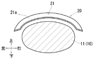
- FIG. 4 is a sectional view taken along the line IV-IV in FIG. 1. It is a side view of the connection part of the cabin and deck of a vehicle.
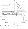
- FIG. 1 shows a silencer 11 located in the middle of the exhaust pipe system 10 of the vehicle 1 and its surroundings.
- the vehicle 1 is a pickup type freight vehicle, and includes a cabin 2 at the front and a deck 3 at the rear. A gap 4 is formed between the rear surface of the cabin 2 and the front surface of the deck 3.
- the exhaust pipe system 10 mainly has an exhaust pipe that exhausts the exhaust of the engine mounted in the front part of the cabin 2 to the rear of the vehicle.
- the exhaust pipe system 10 extends to the rear portion of the vehicle 1 along the lower surfaces of the cabin (floor) 2 and the deck (floor) 3.
- a silencer 11 for silencing is interposed in the middle of the exhaust pipe system 10.
- the silencer 11 is located below the gap 4 between the cabin 2 and the deck 3.
- the silencer 11 has a cylindrical body having an elliptical cross section.
- the top surface of the silencer 11 is curved so that the center in the vehicle width direction (left-right direction) is high and the left-right side is lower.
- a heat shield 20 is disposed between the upper surface of the silencer 11 and the lower surface of the cabin 2.
- the heat shield plate 20 is a press-formed product of a steel plate and has a generally curved shape along the upper surface of the silencer 11. As shown in FIG. 4, the heat shield plate 20 covers the entire silencer 11 in the vehicle width direction. The heat shield plate 20 extends over the silencer 11 in the left-right direction.
- the rear part of the heat shield 20 reaches below the gap 4.
- the heat shield plate 20 is provided with three coupling pedestals 20a.
- the coupling pedestal 20a is brought into contact with the lower surface of the cabin 2, and the heat shield plate 20 is coupled to the lower surface of the cabin 2 with bolts.
- a groove 21 is provided at a portion installed below the gap 4.
- the groove 21 has a concave shape.
- the groove 21 has a substantially V-shaped cross section and is formed when the heat shield plate 20 is press-formed.
- the groove 21 extends in the vehicle width direction (left-right direction) at the rear portion of the heat shield plate 20 and reaches both the left and right sides of the heat shield plate 20.
- a front wall portion 21a is formed in front of the groove 21, and a rear wall portion 21b is formed behind.
- the groove 21 is curved along the upper surface of the silencer 11 such that the center in the vehicle width direction is high and the left and right sides are low. The left and right parts of the groove 21 reach the left and right parts of the silencer 11.
- the heat shield plate 20 covers the upper part of the exhaust pipe system 10 arranged along the lower surface of the vehicle floor (2, 3) as shown in FIG.
- the heat shield plate 20 has a groove 21 extending in the vehicle width direction so as to guide small items placed on the heat shield plate 20 to the side of the exhaust pipe system 10.
- the groove 21 is provided using the heat shield plate 20. Therefore, it is possible to avoid the trouble that small items burn out without providing a dedicated member or the like separately. There are cases where the small items are jumped up from the road surface and placed on the heat shield plate during traveling of the vehicle, or dropped from the gap between the cabin and the deck in a pickup type truck.
- the groove 21 is located below the gap 4 formed between the cabin 2 and the deck 3, and is configured to guide small items that have fallen into the groove 21 from the gap 4 to the side of the exhaust pipe system 10. . For this reason, in a freight vehicle such as a pickup, small items dropped from the gap 4 are guided to the side of the exhaust pipe system 10 through the groove 21 and fall to the road surface. Thus, the groove 21 functions to remove small items. Therefore, troubles such as burning of small items by heat of the exhaust pipe system 10 can be avoided in advance.
- the groove 21 is curved such that the center in the vehicle width direction is high and the side in the vehicle width direction is lower. For this reason, the small items dropped or placed in the groove 21 move to the side in the vehicle width direction and are removed from the heat shield plate 20 without staying in the groove 21. As a result, the small items surely fall to the side of the exhaust pipe system.
- the heat shield 20 extends beyond the silencer 11 to the left and right sides. Therefore, the small items surely fall on the road surface from the groove 21 beyond the silencer.
- the silencer 11 and the catalytic converter of the exhaust pipe system 10 usually have an elliptical cross section. Therefore, the heat shield plate 20 is curved along the arc side surface of the silencer 11.
- the groove 21 can be similarly curved without greatly changing the basic shape of the heat shield plate 20.
- Small items such as pebbles that are thrown up while driving may enter the groove 21.
- Such small items are also reliably removed from the heat shield plate 20. Therefore, it is possible to prevent the generation of abnormal noise during traveling by such small items, and it is possible to avoid troubles due to burning of such small items.
- the front wall 21a and the rear wall 21b of the groove 21 are located below the gap 4.
- the front wall portion 21a and the rear wall portion 21b prevent small objects that have fallen into the groove 21 from the gap 4 from moving from the groove 21 to the front side or the rear side. For this reason, even if the heat shield 20 does not cover, for example, the rear part of the silencer 11 as shown in FIGS. Therefore, small items that fall into the groove 21 are reliably removed on the road surface through the left and right side portions.
- the groove 21 may be formed integrally with the heat shield plate 20 when the heat shield plate 20 is press-molded.
- a member having a groove may be manufactured separately from the main body of the heat shield plate. The member may be manufactured by pressing a steel plate or the like, and may be attached to the main body of the heat shield so as to be positioned below the gap 4.
- the groove may have a V-shaped cross section, a U-shaped cross section, a U-shaped cross section, or a semicircular cross section.
- the groove 21 may be curved in the vehicle width direction along an elliptical cross section of the silencer 11 or the catalytic converter.
- the groove may be a mountain shape inclined so as to descend from side to side with the center in the vehicle width direction as a vertex.
- the groove may be horizontal. Small items that fall into such a groove are prevented from moving forward or backward by the front wall portion and the rear wall portion. Therefore, the small objects move along the groove, fall from the groove onto the road surface, and are removed from the heat shield plate. This prevents small items from falling from the heat shield onto the silencer 11.
- the grooves may be provided not only below the gap 4 between the cabin 2 and the deck 3 but also at a plurality of places including other parts.
- the heat shield plate 21 may cover the upper surface of the silencer 11 of the exhaust pipe system 10 as described above. Instead of this, the heat shield plate may cover the exhaust pipe portion or the catalytic converter or the like piped before and after the silencer 11. And the same groove
- the vehicle is a pickup type as described above, and may include the cabin 2 and the deck 3. Alternatively, the vehicle may be a sedan-type passenger car or the like or another type.
- the heat shield plate 20 may be applied to the vehicle.
Landscapes
- Engineering & Computer Science (AREA)
- Chemical & Material Sciences (AREA)
- Combustion & Propulsion (AREA)
- Mechanical Engineering (AREA)
- Transportation (AREA)
- General Engineering & Computer Science (AREA)
- Cooling, Air Intake And Gas Exhaust, And Fuel Tank Arrangements In Propulsion Units (AREA)
- Body Structure For Vehicles (AREA)
- Exhaust Silencers (AREA)
Description
本発明は、車両の遮熱板(ヒートインシュレータ)に関する。
エンジンが車両の前部に搭載される場合、排気管系が車両フロアの下面に沿って装備されて車両前部から後部に延出する。排気管系は高温の熱源になる。このため排気管系からキャビン等への熱影響を小さくするために、排気管系と車両フロアの間に適度な間隔が設けられる。排気管系の中途にサイレンサと触媒コンバータが設けられ、サイレンサと車両フロアの間あるいは触媒コンバータと車両フロアの間に鋼板製の遮熱板が配置される。遮熱板は、サイレンサ等の上方を遮蔽し、熱が直接キャビンへ伝わることを低減する。遮熱板は、特開平9-175198号公報、特開平11-5567号公報に開示されている。
セダンタイプの車両では、遮熱板の上方が車両フロアで覆われる。しかし図5に示すようにいわゆるピックアップ形式の貨物車両1では、キャビン2の後面とデッキ(荷台)3の前面との間に隙間4がある。隙間4の下方に排気管系10のサイレンサ11が位置している場合、隙間4から紙片やプラスチック製の小物類(落下物)が落下してサイレンサ11上に留まる場合がある。この場合、落下物がサイレンサ11の熱によって焼損するおそれがある。
図5の二点鎖線で示すようにサイレンサ11は、熱が排気管系から直接キャビン2内へ伝わることを低減するために遮熱板12によって上方から覆われる。隙間4から落下物が遮熱板12に留まった場合および落下物が遮熱板12上からさらに落下して排気管系10に引っ掛かり留まった場合、同様に落下物がサイレンサ11の熱によって焼損するおそれがある。
したがって落下物(小物類)が遮熱板上若しくは排気管系上に留まらない構造が従来必要とされている。すなわち落下物が路面へ確実に落下し、これによって落下物が焼損することを回避し得る構造が必要とされている。
本発明の1つの特徴によると遮熱板は、車両フロアの下面に沿って配される排気管系の上方を覆う。遮熱板は、遮熱板の上に載った小物類を排気管系の側方へ案内するように車幅方向に延出する溝を有する。
したがって溝内に載った小物類は、排気管系の側方へ案内されて路面に落下する。そのため溝の前側及び後ろ側に位置する壁部を乗り越えて溝の前方及び後方に位置する排気管系上に落下することが防止される。
本発明の実施形態を図1~4に基づいて説明する。図1は、車両1の排気管系10の中途部位に位置するサイレンサ11及びその周辺を示す。車両1は、ピックアップ形式の貨物車両であって、前部にキャビン2、後部にデッキ3を備える。キャビン2の後面とデッキ3の前面の間に隙間4が形成される。
排気管系10は、キャビン2の前部に搭載したエンジンの排気を車両の後方に排出する排気管を主体に有する。排気管系10は、キャビン(フロア)2及びデッキ(フロア)3の下面に沿って車両1の後部まで延出する。排気管系10の中途に消音用のサイレンサ11が介装される。サイレンサ11は、キャビン2とデッキ3の間の隙間4の下方に位置する。図4に示すようにサイレンサ11は、断面楕円形の筒体を有する。サイレンサ11の上面は、車幅方向(左右方向)中央が高く、左右側方ほど低くなるように湾曲する。
図1に示すようにサイレンサ11の上面とキャビン2の下面の間に遮熱板20が配置される。遮熱板20は鋼板のプレス成形品であって、サイレンサ11の上面に沿う概ね湾曲形状を有する。図4に示すように遮熱板20は、サイレンサ11の車幅方向の全体を覆う。遮熱板20は、サイレンサ11を超えて左右方向に張出す。
遮熱板20の後部は、隙間4の下方に至る。図3に示すように遮熱板20に3箇所の結合台座部20aが設けられる。結合台座部20aがキャビン2の下面に当接され、遮熱板20がキャビン2の下面にボルトで結合される。遮熱板20の後部には、隙間4の下方に設置される部位にて溝21が設けられる。溝21は、凹形状である。溝21は、断面概ねV字形で、遮熱板20のプレス成形時に形成される。
溝21は、遮熱板20の後部において車幅方向(左右方向)に延び、遮熱板20の左右両側部に至る。溝21の前に前壁部21aが形成され、後に後ろ壁部21bが形成される。図4に示すように溝21は、サイレンサ11の上面に沿って車幅方向中央が高く、左右側方が低くなるように湾曲する。溝21の左右部は、サイレンサ11の左右部に至る。
以上のように遮熱板20は、図1に示すように車両フロア(2,3)の下面に沿って配される排気管系10の上方を覆う。遮熱板20は、遮熱板20の上に載った小物類を排気管系10の側方へ案内するように車幅方向に延出する溝21を有する。
したがって溝21内に載った小物類は、排気管系11の側方へ案内されて路面に落下する。そのため溝21の前側及び後ろ側に位置する壁部を乗り越えて溝21の前方及び後方に位置する排気管系上に落下することが防止される。
遮熱板20を利用して溝21を設ける。そのため別途専用の部材等を設けることなく小物類が焼損するトラブルを未然に回避できる。小物類は、車両走行中等において路面から跳ね上げられて遮熱板上に載る場合、あるいはピックアップ形式のトラックにおいてキャビンとデッキ間の隙間から落下する場合等がある。
溝21は、キャビン2とデッキ3間に形成される隙間4の下方に位置して、隙間4から溝21内に落下した小物類を排気管系10の側方へ案内するように構成される。このためピックアップ等の貨物車両において、隙間4から落下した小物類は、溝21を経て排気管系10の側方に案内して路面に落下する。かくして溝21は、小物類を除去する機能を奏する。そのため小物類が排気管系10の熱によって焼損等するトラブルが未然に回避され得る。
溝21は、車幅方向中央が高く、車幅方向側部ほど低くなるように湾曲する。このため、溝21内に落下若しくは載った小物類は、溝21内に留まることなく、車幅方向側方へ移動して遮熱板20上から除去される。これにより小物類は、確実に排気管系の側方に落下する。遮熱板20は、サイレンサ11を超えて左右両側へ張出す。そのため小物類は、サイレンサを超えて確実に溝21から路面上に落下する。
排気管系10のサイレンサ11や触媒コンバータ等は、通常断面楕円形を有する。そのため遮熱板20は、サイレンサ11の円弧側面に沿って湾曲する。溝21は、遮熱板20の基本的形状を大きく変更することなく同様に湾曲し得る。
隙間4からスパナ等の工具や金具が誤って落下する場合がある。スパナ等は、焼損等するおそれのない小物類である。しかしこのような小物類も溝21によって遮熱板20上から路面へ確実に排除できる。このためこのような小物類が車両の走行時に遮熱板20上にて振動することで生じる異音を未然に防止できる。
走行中に跳ね上げられた小石等の小物類が溝21内に入る場合がある。このような小物類も遮熱板20から確実に除去される。そのためこのような小物類による走行中の異音の発生を防止でき、かつこのような小物類の焼損等によるトラブルも未然に回避できる。
隙間4の下方に溝21の前壁部21aと後ろ壁部21bが位置する。前壁部21aと後ろ壁部21bは、隙間4から溝21内に落下した小物類が溝21内から前側若しくは後ろ側に移動することを阻止する。このため図1,2に示すように遮熱板20がサイレンサ11の例えば後部を覆っていない場合でも、小物類がサイレンサ11の後部上面にさらに落下することが防止される。したがって溝21内に落下した小物類は、左右側部を経て確実に路面上に除去される。
本発明の形態を上記構造を参照して説明したが、本発明の目的を逸脱せずに多くの交代、改良、変更が可能であることは当業者であれば明らかである。したがって本発明の形態は、添付された請求項の精神と目的を逸脱しない全ての交代、改良、変更を含み得る。例えば本発明の形態は、前記特別な構造に限定されず、下記のように変更が可能である。
上述するように遮熱板20のプレス成形時に溝21が遮熱板20に一体に形成されても良い。これに代えて溝を有する部材が遮熱板の本体と別個に製作されても良い。該部材は、鋼板をプレス加工等により製作され、隙間4の下方に位置するように遮熱板の本体に取付けられても良い。
溝は、断面V字形でも良いし、断面U字形、断面コ字形、断面半円形でも良い。
上述するように溝21は、サイレンサ11若しくは触媒コンバータ等の断面楕円形状に沿って車幅方向に湾曲しても良い。これに代えて溝は、車幅方向中央を頂点として左右に下るように傾斜した山形でも良い。
溝は、水平でも良い。このような溝内に落下した小物類は、前壁部と後ろ壁部によって前方若しくは後方へ移動することが阻止される。そのため小物類は、溝に沿って移動して溝から路面上へ落下し、遮熱板上から除去される。これにより小物類が遮熱板からサイレンサ11上に落下することが防止される。
溝は、キャビン2とデッキ3間の隙間4の下方のみならず、その他の部位を含める複数箇所に設けられても良い。
遮熱板21は、上述するように排気管系10のサイレンサ11の上面を覆っても良い。これに代えて遮熱板は、サイレンサ11の前後に配管された排気管部あるいは触媒コンバータ等を覆っても良い。そして該遮熱板に同様の溝が設けられても良い。
車両は、上述のようにピックアップ型であって、キャビン2とデッキ3を備えても良い。これに代えて車両は、セダン形の乗用車等あるいは他の形式でも良い。そして該車両に遮熱板20が適用されても良い。
Claims (3)
- 車両フロアの下面に沿って配される排気管系の上方を覆う遮熱板であって、
前記遮熱板の上に載った小物類を前記排気管系の側方へ案内するように車幅方向に延出する溝を有する遮熱板。 - 請求項1に記載の遮熱板であって、
前記溝は、前記車両のキャビンとデッキの間に形成される隙間の下方に位置して前記隙間から前記溝内に落下した小物類を前記排気管系の側方へ案内するように構成された遮熱板。 - 請求項1又は2に記載の遮熱板であって、
前記溝は、車幅方向中央が高く、車幅方向側部ほど低くなるように湾曲する遮熱板。
Applications Claiming Priority (2)
| Application Number | Priority Date | Filing Date | Title |
|---|---|---|---|
| JP2012-063191 | 2012-03-21 | ||
| JP2012063191A JP2013193582A (ja) | 2012-03-21 | 2012-03-21 | 車両の遮熱板 |
Publications (1)
| Publication Number | Publication Date |
|---|---|
| WO2013140641A1 true WO2013140641A1 (ja) | 2013-09-26 |
Family
ID=49222130
Family Applications (1)
| Application Number | Title | Priority Date | Filing Date |
|---|---|---|---|
| PCT/JP2012/071974 Ceased WO2013140641A1 (ja) | 2012-03-21 | 2012-08-30 | 車両の遮熱板 |
Country Status (2)
| Country | Link |
|---|---|
| JP (1) | JP2013193582A (ja) |
| WO (1) | WO2013140641A1 (ja) |
Families Citing this family (1)
| Publication number | Priority date | Publication date | Assignee | Title |
|---|---|---|---|---|
| JP7040256B2 (ja) * | 2018-04-24 | 2022-03-23 | トヨタ自動車株式会社 | 車両床下のプロテクタ |
Citations (6)
| Publication number | Priority date | Publication date | Assignee | Title |
|---|---|---|---|---|
| JPS57116580U (ja) * | 1981-01-13 | 1982-07-19 | ||
| JPS57167877A (en) * | 1981-04-09 | 1982-10-15 | Nissan Motor Co Ltd | Construction of car body |
| JPS60180715U (ja) * | 1984-05-11 | 1985-11-30 | 三菱自動車工業株式会社 | 汎用排気管防火インシユレ−タ |
| JPH08150844A (ja) * | 1994-11-28 | 1996-06-11 | Hitachi Constr Mach Co Ltd | 建設機械用マフラ |
| JPH09175198A (ja) * | 1995-12-27 | 1997-07-08 | Hino Motors Ltd | 車両用ヒートインシュレータ |
| JPH115567A (ja) * | 1997-06-18 | 1999-01-12 | Nissan Motor Co Ltd | 車両のアンダフロア遮熱板 |
-
2012
- 2012-03-21 JP JP2012063191A patent/JP2013193582A/ja active Pending
- 2012-08-30 WO PCT/JP2012/071974 patent/WO2013140641A1/ja not_active Ceased
Patent Citations (6)
| Publication number | Priority date | Publication date | Assignee | Title |
|---|---|---|---|---|
| JPS57116580U (ja) * | 1981-01-13 | 1982-07-19 | ||
| JPS57167877A (en) * | 1981-04-09 | 1982-10-15 | Nissan Motor Co Ltd | Construction of car body |
| JPS60180715U (ja) * | 1984-05-11 | 1985-11-30 | 三菱自動車工業株式会社 | 汎用排気管防火インシユレ−タ |
| JPH08150844A (ja) * | 1994-11-28 | 1996-06-11 | Hitachi Constr Mach Co Ltd | 建設機械用マフラ |
| JPH09175198A (ja) * | 1995-12-27 | 1997-07-08 | Hino Motors Ltd | 車両用ヒートインシュレータ |
| JPH115567A (ja) * | 1997-06-18 | 1999-01-12 | Nissan Motor Co Ltd | 車両のアンダフロア遮熱板 |
Also Published As
| Publication number | Publication date |
|---|---|
| JP2013193582A (ja) | 2013-09-30 |
Similar Documents
| Publication | Publication Date | Title |
|---|---|---|
| EP3159199B1 (en) | Vehicle underfloor structure | |
| JP5459511B2 (ja) | 車両のバッテリ搭載構造 | |
| US20070240927A1 (en) | Four-wheeled utility vehicle | |
| JP6314757B2 (ja) | 電動車両の車体後部構造 | |
| US11571965B2 (en) | Side vehicle body structure of vehicle | |
| JP2008037396A (ja) | 自動車後部構造 | |
| JP5874213B2 (ja) | 車両の下部車体構造 | |
| JPWO2015045115A1 (ja) | 自動二輪車 | |
| US9512771B2 (en) | Exhaust system structure in internal combustion engine for vehicle | |
| JP2022150183A (ja) | 電動車両の下部構造 | |
| WO2013054564A1 (ja) | 車両前部の下部車体構造 | |
| JP2012166611A (ja) | 車両後部の衝突対応構造 | |
| US8863887B2 (en) | Utility vehicle | |
| WO2013140641A1 (ja) | 車両の遮熱板 | |
| JP2017039371A (ja) | 車体前部構造 | |
| JP2014184818A (ja) | 鞍乗型車両 | |
| JP2012201344A (ja) | 電気自動車のブレーキ配管及びパーキングブレーキ配索構造 | |
| JP2017165213A (ja) | フロントフェンダ支持構造 | |
| JP5145813B2 (ja) | 燃料タンク配置構造 | |
| TW201325971A (zh) | 跨坐型車輛 | |
| JP7347574B1 (ja) | エンジン遮熱構造 | |
| JP2016175530A (ja) | 自動車のヒートインシュレータ | |
| CN210554166U (zh) | 车辆 | |
| JP6657857B2 (ja) | 変速機の冷却構造 | |
| JP2024100238A (ja) | 車両下部構造 |
Legal Events
| Date | Code | Title | Description |
|---|---|---|---|
| 121 | Ep: the epo has been informed by wipo that ep was designated in this application |
Ref document number: 12871842 Country of ref document: EP Kind code of ref document: A1 |
|
| NENP | Non-entry into the national phase |
Ref country code: DE |
|
| 122 | Ep: pct application non-entry in european phase |
Ref document number: 12871842 Country of ref document: EP Kind code of ref document: A1 |