WO2013136972A1 - 接合レンズ、及び接合レンズの製造方法 - Google Patents
接合レンズ、及び接合レンズの製造方法 Download PDFInfo
- Publication number
- WO2013136972A1 WO2013136972A1 PCT/JP2013/054971 JP2013054971W WO2013136972A1 WO 2013136972 A1 WO2013136972 A1 WO 2013136972A1 JP 2013054971 W JP2013054971 W JP 2013054971W WO 2013136972 A1 WO2013136972 A1 WO 2013136972A1
- Authority
- WO
- WIPO (PCT)
- Prior art keywords
- adhesive
- cemented lens
- lens
- outer peripheral
- optical
- Prior art date
- Legal status (The legal status is an assumption and is not a legal conclusion. Google has not performed a legal analysis and makes no representation as to the accuracy of the status listed.)
- Ceased
Links
Images




Classifications
-
- G—PHYSICS
- G02—OPTICS
- G02B—OPTICAL ELEMENTS, SYSTEMS OR APPARATUS
- G02B3/00—Simple or compound lenses
-
- G—PHYSICS
- G02—OPTICS
- G02B—OPTICAL ELEMENTS, SYSTEMS OR APPARATUS
- G02B1/00—Optical elements characterised by the material of which they are made; Optical coatings for optical elements
- G02B1/10—Optical coatings produced by application to, or surface treatment of, optical elements
- G02B1/11—Anti-reflection coatings
Definitions
- the present invention relates to a cemented lens formed by adhering at least two lenses with an adhesive, and a method for manufacturing the same.
- a cemented lens obtained by bonding a plurality of lenses is often used.
- a cemented lens is a glass lens with a different refractive index that is bonded with an adhesive.
- the facing surfaces of the two lenses are formed with the same curvature, convex and concave, and a synthetic resin adhesive is applied between them. Combined is common.
- the room temperature curing type epoxy adhesive it takes several hours to several tens of hours until the two lenses are fixed after being cured to some extent, so that the optical axes of the two lenses do not deviate during that time. You have to keep it pressed.
- distortion is likely to occur due to the influence of heat.
- the ultraviolet curable type since a curing support by heating is finally required, distortion is likely to occur due to the influence of heat.
- the distortion increases and the optical performance deteriorates.
- the lens surface When bonding two lenses with an adhesive, the lens surface may be pulled by the shrinkage of the adhesive when it is cured, causing unnecessary stress to act on the lens and causing distortion in the lens.
- the lens when the environmental temperature changes after the completion of bonding, the lens may be distorted due to the stress stress due to the difference in expansion / contraction between the two lenses. The above phenomenon is unlikely to occur when both lenses have sufficient thickness and sufficient strength, or when there is no significant difference in the coefficient of thermal expansion between the two lens glass materials. If it is thin, it will be distorted and the optical performance will deteriorate. In order to reduce the above problem, it is preferable to self-absorb external stress using a soft adhesive having a small elastic modulus when solidified.
- the lens in order to prevent internal reflection at the lens end face, the lens is coated with an anti-reflective coating on the end face of the lens, but some of the adhesive has the property of infiltrating the solvent contained in the anti-reflective paint.
- the present invention prevents the solvent of the solvent-based antireflection coating from infiltrating the adhesive for bonding the lens even if the solvent-based antireflection coating is applied to the end of the cemented lens, thereby improving the optical quality.
- An object of the present invention is to provide an excellent cemented lens and a manufacturing method thereof.
- the cemented lens according to the present invention is a cemented lens in which the optical surfaces of at least two lenses are bonded to each other with an adhesive, and a solvent-based antireflection coating for preventing internal reflection is applied to a portion outside the optical surface.
- the solvent-free resin is applied so as to cover the edge of the adhesive exposed from between the bonded optical surfaces, and then the solvent-based antireflection paint is applied.
- the solventless resin is preferably an epoxy resin mixed with carbon black or titanium black.
- One of the optical surfaces may be provided with a resin reservoir for the solventless resin on the outside of the outer peripheral edge of the optical surface.
- the resin reservoir is formed outside the optical surface to which the lens positioning flange surface formed in the plane perpendicular to the optical axis is joined, it is preferable that the resin reservoir is formed inside the flange surface.
- the resin reservoir portion is provided between the outer peripheral surface and the outer peripheral edge of the optical surface. It is good to be formed.
- the cemented lens manufacturing method of the present invention includes a step of bonding optical surfaces of at least two lenses with an adhesive, and a solvent-free method so as to cover an end portion of the adhesive exposed between the bonded optical surfaces. And a step of applying a solvent-based antireflection coating for preventing internal reflection on a portion outside the optical surface.
- the solvent of the solvent-based antireflection coating applied to the outer portion of the cemented lens from the optical surface can be prevented from infiltrating the adhesive bonding the lens, the optical quality is excellent.
- a cemented lens, particularly a cemented lens of a large-diameter lens or an ultra-thin lens can be manufactured.
- the optical surface 14 of the convex lens 13 and the optical surface 16 of the concave lens 15 are bonded together with an adhesive 18.
- the optical surface 14 and the optical surface 16 are convex and concave surfaces having the same outer diameter and the same curvature.
- the convex lens 13 has an outer peripheral surface 22 connected to an outer peripheral edge 21 of the optical surface 14.
- the concave lens 15 has a flange portion 24 and is formed between the outer peripheral edge 26 and the outer peripheral surface 27 of the optical surface 16 so as to be formed perpendicular to the optical axis 23 and serving as a positioning surface for the cemented lens 12.
- the adhesive 18 sandwiched between the convex lens 13 and the concave lens 15 extends across the entire range between the optical surfaces 14 and 16, and the outer peripheral end 29 of the extended adhesive 18. Is exposed between the outer peripheral edge 21 of the optical surface of the convex lens 13 and the outer peripheral edge 26 of the optical surface of the concave lens 15, that is, between the outer peripheral surface 22 and the flange surface 25.
- a solventless resin in this embodiment, a solventless epoxy resin 31 mixed with carbon black (hereinafter simply referred to as an epoxy resin 31)
- an epoxy resin 31 is provided with an outer peripheral surface 22 and a flange surface 25. It is applied across. It is desirable that the epoxy resin 31 is applied so as to be in close contact with the outer peripheral end portion 29 of the adhesive 18, but there is no major problem even if a slight air layer is formed between the adhesive 18 and the epoxy resin 31. .
- the longitudinal elastic modulus is measured by dynamic viscoelasticity measurement (DMA: Dynamic Mechanical Analysis). DMA is a technique that measures the mechanical properties of a sample as a function of temperature against vibrational loads (or strains).
- a sample is clamped to a measurement head, heated by a heater, and stress is applied to the sample from a load generation unit via a probe.
- This stress is given as a sinusoidal force with a frequency set as one of the measurement conditions so that the strain amplitude of the sample is constant.
- the amount of deformation (strain) of the sample caused by this sinusoidal force is detected by the displacement detector, and various viscoelastic amounts such as elastic modulus and viscosity are calculated from the stress applied to the sample and the detected strain, Output as a function of temperature or time.
- an epoxy resin is preferable.
- the epoxy resin a room temperature curable epoxy adhesive is more preferably used. Carbon black or titanium black may also be mixed with the solventless resin.
- Solvent-based antireflection coating 32 (hereinafter referred to as antireflection coating 32) (for example, Canon Chemicals GT-7) is applied.
- the outer peripheral surface and flange surface of the cemented lens (outside the optical surfaces 17 and 19 in FIGS. 1 and 2).
- the solvent of the antireflection coating 32 (GT-7) infiltrates into the adhesive 18 between the lenses, and the adhesive 18 swells or dissolves.
- the surface accuracy of the cemented lens 12 was lowered.
- GT-7 contains thinner as a solvent, but there are also antireflection paints containing toluene, xylene and the like.
- the antireflection coating 32 is applied to the end surface portion of the bonded lens, an epoxy resin 31 that is not attacked by a solvent is applied to form a barrier layer on the exposed portion of the adhesive 18, and the adhesive 18 becomes the lens.
- the antireflection paint 32 is applied to the outer peripheral surface and flange surface of the cemented lens (the outer peripheral surfaces 22 and 27 outside the optical surfaces 17 and 19 and the flange surface 25 in FIGS. 1 and 2). No infiltration of the solvent into the adhesive 18 occurred.
- a cemented lens can be manufactured without causing deterioration of surface accuracy such as distortion.
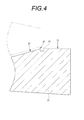
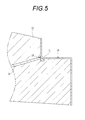
- the concave lens 35 has a bowl-shaped groove 36 formed along the outer peripheral edge 26 on the outer side of the outer peripheral edge 26 of the optical surface 16.
- the bowl-shaped groove 36 serves as a resin reservoir portion of the epoxy resin 31 applied so as to cover the outer peripheral end portion 29 of the adhesive 18, whereby the epoxy resin 31 does not adhere on the flange surface 25. Planar accuracy as the positioning surface of the flange surface 25 is ensured.
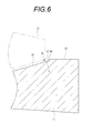
- the concave lens 41 has a surface 43 formed outside the outer peripheral edge 26 and perpendicular to the optical axis 23, and a cylindrical inner wall 44 erected on the outer peripheral edge of the surface 43. And a flange surface 25 is disposed outside the cylindrical inner wall 44.
- the space 42 acts as a resin reservoir portion of the epoxy resin 31 that covers the outer peripheral end 29 of the adhesive 18 inside the flange surface 25, so that the epoxy resin 31 does not adhere to the flange surface 25 and the flange surface 25. The plane accuracy as the positioning surface is ensured.
- the concave lens 45 is not provided with a flange, and the optical surface 14 of the convex lens 13 is formed up to the outer peripheral surface 22, whereas the optical surface 16 of the concave lens 45 is outside the optical surface 16.
- the peripheral edge 26 is closer to the optical axis 23 than the outer peripheral surface 27, and a notch 46 is formed between the outer peripheral edge 26 of the optical surface 16 and the outer peripheral surface 27.
- the notch 46 serves as a resin reservoir portion of the epoxy resin 31 that covers the outer peripheral end portion 29 of the adhesive 18. Thereby, the epoxy resin 31 does not protrude outside the outer peripheral surface 22 and the outer peripheral surface 27, and the accuracy as the positioning surface of the outer peripheral surface 22 and the outer peripheral surface 27 is ensured.
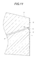
- the resin reservoir formed in the concave lens 47 is a space 48 formed by chamfering an edge portion formed by contact between the optical surface 16 and the outer peripheral surface 27. Since the outer peripheral edge 26 of the optical surface 16 is closer to the optical axis 23 than the outer peripheral surface 27, a space 48 is formed between the optical surface 16 and the outer peripheral surface 27, and this serves as a resin reservoir for the epoxy resin 31. Thereby, the epoxy resin 31 does not protrude outside the outer peripheral surface 22 and the outer peripheral surface 27, and the accuracy as the positioning surface of the outer peripheral surface 22 and the outer peripheral surface 27 is ensured.
- the concave lenses 45 and 47 are provided with notches 46 or spaces 48 as resin reservoirs.
- these resin reservoirs may be provided in the convex lens 13. You may provide in both.
- the said embodiment is bonding of a convex lens and a concave lens, the combination of a lens is not restricted to this, Convex convex or concave may be sufficient, and the surface to be bonded should just be the convex surface and concave surface of the same shape. It may be spherical or aspherical.
- the number of lenses to be bonded is not limited to two, and may be any number.
Landscapes
- Physics & Mathematics (AREA)
- General Physics & Mathematics (AREA)
- Optics & Photonics (AREA)
- Optical Elements Other Than Lenses (AREA)
- Surface Treatment Of Optical Elements (AREA)
- Paints Or Removers (AREA)
- Adhesives Or Adhesive Processes (AREA)
- Lens Barrels (AREA)
Description
本発明は、少なくとも2枚のレンズを接着剤で接着して形成した接合レンズ、及びその製造方法に関する。
近年、光学機器の高性能化に伴ってレンズにも高性能が求められている。単レンズの組合せでは収差補正が十分に行えないことから、複数枚のレンズを貼り合わせた接合レンズが用いられることが多い。接合レンズは、屈折率の異なるガラスレンズを接着剤で貼り合せたものであり、2つのレンズの向き合う面が凸と凹の同じ曲率で形成され、その間に合成樹脂系接着剤を塗布して貼り合わせたものが一般的である。
レンズを接着する接着剤としては、下記特許文献1に記載されるようなエポキシ系接着剤の他に、アクリル系接着剤やエン=チオール系接着剤がある。
エポキシ系接着剤は、室温硬化型の場合、ある程度硬化して2枚のレンズが固着されるまでの時間が数時間~十数時間かかるので、その間、2枚のレンズの光軸がずれないように押えておかなければならない。また、熱硬化型の場合は、熱の影響により歪が発生しやすい。紫外線硬化型の場合も、最終的には加熱による硬化サポートを必要とするので、熱の影響により歪が発生しやすい。特に、厚さが薄いレンズの場合には歪が大きくなり、光学性能が低下してしまう。
これに対し、アクリル系接着剤やエン=チオール系接着剤は、紫外線のみで十分に硬化するので加熱によるサポートを必要とせず、熱による影響を受けない。
エポキシ系接着剤は、室温硬化型の場合、ある程度硬化して2枚のレンズが固着されるまでの時間が数時間~十数時間かかるので、その間、2枚のレンズの光軸がずれないように押えておかなければならない。また、熱硬化型の場合は、熱の影響により歪が発生しやすい。紫外線硬化型の場合も、最終的には加熱による硬化サポートを必要とするので、熱の影響により歪が発生しやすい。特に、厚さが薄いレンズの場合には歪が大きくなり、光学性能が低下してしまう。
これに対し、アクリル系接着剤やエン=チオール系接着剤は、紫外線のみで十分に硬化するので加熱によるサポートを必要とせず、熱による影響を受けない。
2枚のレンズを接着剤で貼り合せるとき、硬化する際の接着剤の収縮によってレンズ表面が引っ張られレンズに不要な応力が作用して、レンズに歪が生じることがある。また、接着完了後、環境温度が変化した場合2枚のレンズの伸び縮みの差による応力ストレスが加わることに起因して、レンズに歪みが生じることがある。2枚のレンズがともに十分な厚みがあって十分な強度を持つ場合や、2つのレンズ硝材の熱膨張率に大きな差がない場合には上記の現象が発生しにくいが、レンズの厚さが薄い場合には歪んでしまい光学性能が低下してしまう。上記の問題を低減するには、固まったときの弾性率が小さく柔らかい接着剤を用いて外部ストレスを自己吸収するようにすることが好ましい。
一般にレンズはレンズ端面における内部反射を防止するために、該レンズ端面に反射防止塗料が塗布されるが、接着剤の中には反射防止塗料に含まれる溶剤が浸潤する性質を有しているものがある。特に、弾性率が小さく、固まった後も柔らかいアクリル系接着剤やエン=チオール系接着剤は、溶剤が浸潤し易い。そのため、これらの接着剤で接合された接合レンズに溶剤系反射防止塗料を塗布すると、反射防止塗料に含まれる溶剤がレンズ接合部分に露呈した接着剤の端部から接着剤の内部に染み込み、接着剤が膨潤あるいは溶解して、接合レンズの光学品質及び機能が著しく劣化してしまう。
本発明は、上記問題に鑑み、接合レンズの端部に溶剤系反射防止塗料を塗布しても、レンズを接合する接着剤に溶剤系反射防止塗料の溶剤が浸潤しないようにして、光学品質に優れた接合レンズ、及びその製造方法を提供することを目的とする。
本発明による接合レンズは、少なくとも2枚のレンズの光学面同士を接着剤によって接合した後に、光学面より外側の部分に内面反射防止用の溶剤系反射防止塗料が塗布された接合レンズであって、接合された光学面の間から露呈した前記接着剤の端部を覆うように無溶剤系樹脂が塗布され、その後に前記溶剤系反射防止塗料が塗布されたことを特徴とする。
前記接着剤は、紫外線硬化型アクリル系接着剤、又は、紫外線硬化型エン=チオール系接着剤であることが好ましい。
更に、紫外線硬化型アクリル系接着剤では20℃における弾性率が100MPa以下であることが好ましく、紫外線硬化型エン=チオール系接着剤では20℃における弾性率が8MPa以下であることが好ましい。
更に、紫外線硬化型アクリル系接着剤では20℃における弾性率が100MPa以下であることが好ましく、紫外線硬化型エン=チオール系接着剤では20℃における弾性率が8MPa以下であることが好ましい。
前記無溶剤系樹脂は、エポキシ樹脂にカーボンブラック又はチタンブラックを混合したものが好ましい。
前記光学面の一方には、該光学面の外周縁の外側に、前記無溶剤系樹脂用の樹脂溜まり部が連設されていると良い。
前記樹脂溜まり部は、光軸と垂直な面内に形成されたレンズ位置決め用フランジ面が接合される光学面の外側に形成されたものでは、該フランジ面の内側に形成されるのが良い。
また、前記樹脂溜まり部は、接合される光学面の外側にフランジ面がなく、レンズ光軸位置を位置決めする外周面が形成されたものでは、該外周面と前記光学面の外周縁との間に形成されるのが良い。
また、本発明の接合レンズ製造方法は、少なくとも2枚のレンズの光学面同士を接着剤によって接合する工程、接合された光学面の間から露呈した前記接着剤の端部を覆うように無溶剤系樹脂を塗布する工程、光学面より外側の部分に内面反射防止用の溶剤系反射防止塗料を塗布する工程、を有することを特徴とする。
前記樹脂溜まり部は、光軸と垂直な面内に形成されたレンズ位置決め用フランジ面が接合される光学面の外側に形成されたものでは、該フランジ面の内側に形成されるのが良い。
また、前記樹脂溜まり部は、接合される光学面の外側にフランジ面がなく、レンズ光軸位置を位置決めする外周面が形成されたものでは、該外周面と前記光学面の外周縁との間に形成されるのが良い。
また、本発明の接合レンズ製造方法は、少なくとも2枚のレンズの光学面同士を接着剤によって接合する工程、接合された光学面の間から露呈した前記接着剤の端部を覆うように無溶剤系樹脂を塗布する工程、光学面より外側の部分に内面反射防止用の溶剤系反射防止塗料を塗布する工程、を有することを特徴とする。
本発明によれば、接合レンズの光学面より外側の部分に塗布される溶剤系反射防止用塗料の溶剤がレンズを貼り合わせている接着剤に浸潤することを防止できるので、光学品質に優れた接合レンズ、特に大口径レンズや超薄型レンズの接合レンズを作製することができる。
図1及び図2に示すように、接合レンズ12は、凸レンズ13の光学面14と凹レンズ15の光学面16とが接着剤18によって貼り合わされる。光学面14と光学面16は同じ外径、同じ曲率の凸面と凹面である。凸レンズ13は光学面14の外周縁21に外周面22が連設されている。凹レンズ15はフランジ部24を有し、光軸23と直交するように形成されて接合レンズ12の位置決め面となるフランジ面25が、光学面16の外周縁26と外周面27の間に形成される。
図3に示すように、凸レンズ13と凹レンズ15とによって挟圧された接着剤18は、光学面14と16の間で、その全範囲に延展され、延展された接着剤18の外周端部29は凸レンズ13の光学面の外周縁21と凹レンズ15の光学面の外周縁26の間、即ち、外周面22とフランジ面25の間に露呈する。露呈した外周端部29には、無溶剤系樹脂(本実施態様では、カーボンブラックが混合された無溶剤系のエポキシ樹脂31(以下、単にエポキシ樹脂31という))が外周面22とフランジ面25とに跨って塗布される。エポキシ樹脂31が接着剤18の外周端部29に密着するように塗布されることが望ましいが、接着剤18とエポキシ樹脂31との間に僅かな空気層が形成された場合でも大きな問題はない。
接着剤18としては、例えば、紫外線硬化型エン=チオール系接着剤や紫外線硬化型アクリル系接着剤が好ましく用いられる。また、20℃における縦弾性率(ヤング率)が8MPa以下の紫外線硬化型エン=チオール系接着剤、あるいは、20℃における縦弾性率が100MPa以下の紫外線硬化型アクリル系接着剤が更に好ましい。なお、ここでいう縦弾性率は、動的粘弾性測定(DMA :Dynamic Mechanical Analysis)により測定される。DMAは振動荷重(または歪)に対する試料の力学的な性質を温度の関数として測定する技法である。DMAにおいて、試料は、測定ヘッドにクランプされ、ヒーターにより加熱されるとともに、荷重発生部からプローブを介して試料に応力が与えられる。この応力は、測定条件の一つとして設定された周波数による正弦波力として、試料の歪振幅が一定となるように与えられる。この正弦波力により生じた試料の変形量(歪)は、変位検出部により検出され、試料に与えた応力と検出した歪から、弾性率や粘性率などの各種の粘弾性量が算出され、温度または時間の関数として出力される。
また、無溶剤系樹脂としては、エポキシ樹脂が好ましい。エポキシ樹脂としては、室温硬化型エポキシ系接着剤が更に好ましく用いられる。無溶剤系樹脂には、また、カーボンブラックやチタンブラックを混合させても良い。
また、無溶剤系樹脂としては、エポキシ樹脂が好ましい。エポキシ樹脂としては、室温硬化型エポキシ系接着剤が更に好ましく用いられる。無溶剤系樹脂には、また、カーボンブラックやチタンブラックを混合させても良い。
塗布されたエポキシ樹脂31とフランジ面25とを含む凸レンズ13の外周面22から凹レンズ15の外周面27までの全ての範囲(上述した「光学面より外側の部分」)を覆うように内面反射防止用の溶剤系反射防止塗料32(以下、反射防止塗料32という)(例えば、キャノン化成のGT-7)が塗布される。
次に、上記実施態様の作用・効果について説明する。中心部分が極めて薄い凹レンズ15と凸レンズ13の接着に、20℃における弾性率が1~14MPaの範囲内から数種の紫外線硬化型エン=チオール系接着剤を選んで接合レンズ12試作し、面精度を目視により判断した。その結果、弾性率が1.2、2.4、又は7.8MPaの紫外線硬化型エン=チオール系接着剤を使用した接合レンズには、面精度に変化が観察されなかったが、弾性率が8.9、11、又は13.5MPaの紫外線硬化型エン=チオール系接着剤を使用した接合レンズには、接合レンズとしての使用の許容範囲内ではあるものの、面精度に変化が観察された。
また、紫外線硬化型アクリル系接着剤を使用して同様に接合レンズを試作したところ、20℃における弾性率が約100MPa以下の紫外線硬化型アクリル系接着剤を使用した接合レンズには、面精度に変化が観察されなかったが、弾性率が123、又は135MPaの紫外線硬化型アクリル系接着剤を使用した接合レンズには、接合レンズとしての使用の許容範囲内ではあるものの、面精度に変化が観察された。
上記テストで接合レンズの面精度の変化を起こさなかった接着剤18を用いた接合レンズを用いて、接合したレンズの外周面やフランジ面(図1、図2における光学面17,19より外側の外周面22,27及びフランジ面25)に反射防止塗料32を塗布したところ、反射防止塗料32(GT-7)の溶剤がレンズ間の接着剤18に浸潤、接着剤18が膨潤あるいは溶解し、接合レンズ12の面精度が低下した。GT-7は溶剤としてシンナーを含んでいるがトルエンやキシレンなどを含む反射防止塗料もある。
次に、接合されたレンズの端面部分に反射防止塗料32を塗布する前に、溶剤に侵されないエポキシ樹脂31を塗布して接着剤18の露呈部分にバリア層を形成し、接着剤18がレンズから露呈しないようにした。その後、接合したレンズの外周面やフランジ面(図1、図2における光学面17,19より外側の外周面22,27及びフランジ面25)に反射防止塗料32を塗布したところ、反射防止塗料32の溶剤の接着剤18への浸潤は発生しなかった。これによって、凹レンズ15のような中心部分が極めて薄いレンズを貼り合わせる場合でも、歪などの面精度の悪化を発生させることなく、接合レンズが製造できることが分かった。
次に、別の実施形態について説明するが、前記実施形態に記載したものと同じ形状・同じ機能のものは同じ符号を付して説明を省略する。図4及び図5に示すように、凹レンズ35は、光学面16の外周縁26の外側に該外周縁26に沿って樋状の溝36が形成されている。樋状の溝36は接着剤18の外周端部29を覆うように塗布されたエポキシ樹脂31の樹脂溜まり部の役目を果たし、これによって、エポキシ樹脂31がフランジ面25の上に付着しないので、フランジ面25の位置決め面としての平面精度が確保される。
次に、第3の実施形態について説明する。図6及び図7に示すように、凹レンズ41には、外周縁26より外側に形成された、光軸23に対して垂直な面43と、面43の外周縁に立設された円筒内壁44とによるスペース42が設けられ、円筒内壁44の外側にフランジ面25が配置される。スペース42はフランジ面25の内側で接着剤18の外周端部29を覆うエポキシ樹脂31の樹脂溜まり部のとして作用し、エポキシ樹脂31がフランジ面25の上に付着することがなく、フランジ面25の位置決め面としての平面精度が確保される。
次に、第4の実施形態について説明する。図8及び図9に示すように、凹レンズ45はフランジ部が設けられておらず、凸レンズ13の光学面14が外周面22まで形成されているのに対して、凹レンズ45の光学面16の外周縁26は外周面27より光軸23寄りとなっており、光学面16の外周縁26と外周面27の間に切り欠き46が形成されている。この切り欠き46は接着剤18の外周端部29を覆うエポキシ樹脂31の樹脂溜まり部の役目をする。これによって、エポキシ樹脂31が外周面22及び外周面27より外側にはみ出すことがなく、外周面22及び外周面27の位置決め面としての精度が確保される。
次に、第5の実施形態について説明するが、第4の実施形態における樹脂溜まり部(切り欠き46)の形状が異なる点以外は同じである。図10及び図11に示すように、凹レンズ47に形成された樹脂溜まり部は、光学面16と外周面27とが接してできるエッジ部を面取りして形成されたスペース48である。光学面16の外周縁26は外周面27より光軸23寄りとなるので、光学面16と外周面27の間にスペース48が形成され、これがエポキシ樹脂31の樹脂溜まり部の役目をする。これによって、エポキシ樹脂31が外周面22及び外周面27より外側にはみ出すことがなく、外周面22及び外周面27の位置決め面としての精度が確保される。
なお、前記第4,第5の実施形態において、凹レンズ45,47に樹脂溜まり部として切り欠き46又はスペース48を設けたが、これらの樹脂溜まり部は凸レンズ13に設けても良く、凹レンズと凸レンズの両方に設けても良い。また、前記実施形態は凸レンズと凹レンズの貼り合せであるが、レンズの組み合わせはこれに限るものではなく、凸凸でも、凹凹でも良く、貼り合わされる面が同じ形状の凸面と凹面であれば良く、球面でも非球面でも良い。更に、貼り合わされるレンズの枚数は2枚に限らず、何枚でも良い。
12 接合レンズ
13 凸レンズ
14,16,17,19 光学面
15,35,41,45,47 凹レンズ
18 接着剤
21,26 光学面の外周縁
22,27 レンズの外周面
23 光軸
24 フランジ部
25 フランジ面
29 (接着剤18の)外周端部
31 (無溶剤系の)エポキシ樹脂
32 (溶剤系)反射防止塗料
36 樋状の溝(樹脂溜まり部)
42,48 スペース(樹脂溜まり部)
43 垂直な面
44 円筒内壁
46 切り欠き(樹脂溜まり部)
13 凸レンズ
14,16,17,19 光学面
15,35,41,45,47 凹レンズ
18 接着剤
21,26 光学面の外周縁
22,27 レンズの外周面
23 光軸
24 フランジ部
25 フランジ面
29 (接着剤18の)外周端部
31 (無溶剤系の)エポキシ樹脂
32 (溶剤系)反射防止塗料
36 樋状の溝(樹脂溜まり部)
42,48 スペース(樹脂溜まり部)
43 垂直な面
44 円筒内壁
46 切り欠き(樹脂溜まり部)
Claims (9)
- 少なくとも2枚のレンズの光学面同士を接着剤によって接合した後に、光学面より外側の部分に内面反射防止用の溶剤系反射防止塗料が塗布された接合レンズであって、
接合された光学面の間から露呈した前記接着剤の端部を覆うように無溶剤系樹脂が塗布され、その後に前記溶剤系反射防止塗料が塗布されたことを特徴とする接合レンズ。 - 前記接着剤は、紫外線硬化型エン=チオール系接着剤、又は、紫外線硬化型アクリル系接着剤である請求項1記載の接合レンズ。
- 前記紫外線硬化型エン=チオール系接着剤は、20℃における弾性率が8MPa以下である請求項2記載の接合レンズ。
- 前記紫外線硬化型アクリル系接着剤は、20℃における弾性率が100MPa以下である請求項2記載の接合レンズ。
- 前記無溶剤系樹脂は、エポキシ樹脂にカーボンブラック又はチタンブラックを混合したものである請求項1~4いずれか一項に記載の接合レンズ。
- 前記光学面の一方には、該光学面の外周縁の外側に、前記無溶剤系樹脂用の樹脂溜まり部が連設されている請求項1~5いずれか一項に記載の接合レンズ。
- 前記樹脂溜まり部は、光軸と垂直な面内に形成されたレンズ位置決め用フランジ面の内側に位置してなる請求項6記載の接合レンズ。
- 前記樹脂溜まり部は、レンズの光軸位置を位置決めする外周面と前記光学面の外周縁との間に位置してなる請求項6記載の接合レンズ。
- 少なくとも2枚のレンズの光学面同士を接着剤によって接合する工程、
接合された光学面の間から露呈した前記接着剤の端部を覆うように無溶剤系樹脂を塗布する工程、及び、
光学面より外側の部分に内面反射防止用の溶剤系反射防止塗料を塗布する工程、を有することを特徴とする接合レンズの製造方法。
Applications Claiming Priority (2)
| Application Number | Priority Date | Filing Date | Title |
|---|---|---|---|
| JP2012-054505 | 2012-03-12 | ||
| JP2012054505A JP2015108642A (ja) | 2012-03-12 | 2012-03-12 | 接合レンズ |
Publications (1)
| Publication Number | Publication Date |
|---|---|
| WO2013136972A1 true WO2013136972A1 (ja) | 2013-09-19 |
Family
ID=49160888
Family Applications (1)
| Application Number | Title | Priority Date | Filing Date |
|---|---|---|---|
| PCT/JP2013/054971 Ceased WO2013136972A1 (ja) | 2012-03-12 | 2013-02-26 | 接合レンズ、及び接合レンズの製造方法 |
Country Status (2)
| Country | Link |
|---|---|
| JP (1) | JP2015108642A (ja) |
| WO (1) | WO2013136972A1 (ja) |
Cited By (4)
| Publication number | Priority date | Publication date | Assignee | Title |
|---|---|---|---|---|
| JP2016194609A (ja) * | 2015-03-31 | 2016-11-17 | キヤノン株式会社 | 光学素子、それを有する光学機器 |
| JP2016194610A (ja) * | 2015-03-31 | 2016-11-17 | キヤノン株式会社 | 光学素子、それを有する光学機器及び製造方法 |
| JP2017227938A (ja) * | 2017-10-06 | 2017-12-28 | キヤノン株式会社 | 光学機器 |
| US12216294B2 (en) | 2021-03-31 | 2025-02-04 | Seiko Epson Corporation | Optical element, projection optical apparatus, and projector |
Families Citing this family (7)
| Publication number | Priority date | Publication date | Assignee | Title |
|---|---|---|---|---|
| JP6859031B2 (ja) * | 2016-07-04 | 2021-04-14 | キヤノン株式会社 | 光学素子及びそれを有する光学機器 |
| JP7118615B2 (ja) | 2017-10-12 | 2022-08-16 | キヤノン株式会社 | 光学素子、光学系および撮像装置 |
| JP7301508B2 (ja) * | 2018-08-08 | 2023-07-03 | キヤノン株式会社 | 接合レンズ、およびそれを有する光学系、および光学機器、および接合レンズの製造方法 |
| WO2020217288A1 (ja) * | 2019-04-22 | 2020-10-29 | カンタム・ウシカタ株式会社 | 光学系装置 |
| JP7551363B2 (ja) | 2020-07-01 | 2024-09-17 | キヤノン株式会社 | 光学素子の製造方法、光学素子、光学機器および撮像装置 |
| JP7575256B2 (ja) | 2020-12-04 | 2024-10-29 | 株式会社タムロン | 接合レンズ、およびそれを備えた光学系、および光学機器、および接合レンズの製造方法 |
| JP2022118214A (ja) * | 2021-02-24 | 2022-08-12 | マクセル株式会社 | 接合レンズ、レンズユニットおよびカメラ |
Citations (5)
| Publication number | Priority date | Publication date | Assignee | Title |
|---|---|---|---|---|
| JPS58120217A (ja) * | 1982-01-12 | 1983-07-18 | Hoya Corp | プラスチツク製2重焦点レンズ |
| JPH0519104A (ja) * | 1991-07-12 | 1993-01-29 | Pioneer Electron Corp | 貼り合わせレンズ |
| JP2008304831A (ja) * | 2007-06-11 | 2008-12-18 | Toppan Printing Co Ltd | 光学部材およびその製造方法 |
| JP2010014780A (ja) * | 2008-07-01 | 2010-01-21 | Toppan Printing Co Ltd | 積層体、画像形成体及びその製造方法 |
| JP2010181601A (ja) * | 2009-02-05 | 2010-08-19 | Toray Ind Inc | ディスプレイ用フィルター |
-
2012
- 2012-03-12 JP JP2012054505A patent/JP2015108642A/ja active Pending
-
2013
- 2013-02-26 WO PCT/JP2013/054971 patent/WO2013136972A1/ja not_active Ceased
Patent Citations (5)
| Publication number | Priority date | Publication date | Assignee | Title |
|---|---|---|---|---|
| JPS58120217A (ja) * | 1982-01-12 | 1983-07-18 | Hoya Corp | プラスチツク製2重焦点レンズ |
| JPH0519104A (ja) * | 1991-07-12 | 1993-01-29 | Pioneer Electron Corp | 貼り合わせレンズ |
| JP2008304831A (ja) * | 2007-06-11 | 2008-12-18 | Toppan Printing Co Ltd | 光学部材およびその製造方法 |
| JP2010014780A (ja) * | 2008-07-01 | 2010-01-21 | Toppan Printing Co Ltd | 積層体、画像形成体及びその製造方法 |
| JP2010181601A (ja) * | 2009-02-05 | 2010-08-19 | Toray Ind Inc | ディスプレイ用フィルター |
Cited By (4)
| Publication number | Priority date | Publication date | Assignee | Title |
|---|---|---|---|---|
| JP2016194609A (ja) * | 2015-03-31 | 2016-11-17 | キヤノン株式会社 | 光学素子、それを有する光学機器 |
| JP2016194610A (ja) * | 2015-03-31 | 2016-11-17 | キヤノン株式会社 | 光学素子、それを有する光学機器及び製造方法 |
| JP2017227938A (ja) * | 2017-10-06 | 2017-12-28 | キヤノン株式会社 | 光学機器 |
| US12216294B2 (en) | 2021-03-31 | 2025-02-04 | Seiko Epson Corporation | Optical element, projection optical apparatus, and projector |
Also Published As
| Publication number | Publication date |
|---|---|
| JP2015108642A (ja) | 2015-06-11 |
Similar Documents
| Publication | Publication Date | Title |
|---|---|---|
| WO2013136972A1 (ja) | 接合レンズ、及び接合レンズの製造方法 | |
| EP2247971B1 (en) | Method and means for mounting a fibre Bragg grating on a surface | |
| JP6979960B2 (ja) | レンズユニットおよび撮像装置 | |
| US6816322B2 (en) | Cemented lens group | |
| WO2008142807A1 (ja) | 撮像レンズ | |
| JP2012230211A (ja) | 光学系、およびそれを用いた光学機器 | |
| CN105758323B (zh) | 一种基于fbg传感器测试薄试件应变的方法 | |
| CN112269236A (zh) | 一种红外冷光学透镜柔性支撑结构及其装配方法 | |
| JP5848109B2 (ja) | 樹脂硬化収縮測定方法 | |
| CN213986963U (zh) | 一种红外冷光学透镜柔性支撑结构 | |
| JP2003140037A (ja) | 貼合レンズ | |
| JP2008070484A (ja) | レンズユニットの構造 | |
| CN119620322B (zh) | 一种抗力学振动的深低温透镜组的固定方法 | |
| Valente et al. | Interference fit equations for lens cell design using elastomeric lens mountings | |
| JP2003139916A (ja) | 貼合レンズ | |
| JP2003139913A (ja) | 貼合レンズ | |
| JP2004145039A (ja) | 光学部材の結合構造、および光学ユニット | |
| US20120082823A1 (en) | Method for bonding bodies and composite body | |
| WO2023233798A1 (ja) | 光学系 | |
| CN105716535A (zh) | 一种用于测试薄试件应变的传感器组桥方式 | |
| Erbe | Basic considerations for circumferential adhesive bonds in order to reduce lens deformations | |
| TWI627447B (zh) | Method for manufacturing optical component | |
| Bae et al. | Optomechanical Performance of Adhesive Bonding in Airborne EO/IR Systems: A Comparative Study of Bonding Configurations | |
| JP7513513B2 (ja) | レンズユニット、レンズの接着方法、レンズユニットの製造方法およびカメラモジュール | |
| Kihm et al. | Lens mount with ring-flexures for athermalization |
Legal Events
| Date | Code | Title | Description |
|---|---|---|---|
| 121 | Ep: the epo has been informed by wipo that ep was designated in this application |
Ref document number: 13760320 Country of ref document: EP Kind code of ref document: A1 |
|
| NENP | Non-entry into the national phase |
Ref country code: DE |
|
| 122 | Ep: pct application non-entry in european phase |
Ref document number: 13760320 Country of ref document: EP Kind code of ref document: A1 |
|
| NENP | Non-entry into the national phase |
Ref country code: JP |