WO2013136566A1 - 障害物検出機構付きダンプトラックおよびその障害物検出方法 - Google Patents
障害物検出機構付きダンプトラックおよびその障害物検出方法 Download PDFInfo
- Publication number
- WO2013136566A1 WO2013136566A1 PCT/JP2012/073951 JP2012073951W WO2013136566A1 WO 2013136566 A1 WO2013136566 A1 WO 2013136566A1 JP 2012073951 W JP2012073951 W JP 2012073951W WO 2013136566 A1 WO2013136566 A1 WO 2013136566A1
- Authority
- WO
- WIPO (PCT)
- Prior art keywords
- vehicle
- radars
- dump truck
- obstacle detection
- radar
- Prior art date
Links
Images


Classifications
-
- G—PHYSICS
- G01—MEASURING; TESTING
- G01S—RADIO DIRECTION-FINDING; RADIO NAVIGATION; DETERMINING DISTANCE OR VELOCITY BY USE OF RADIO WAVES; LOCATING OR PRESENCE-DETECTING BY USE OF THE REFLECTION OR RERADIATION OF RADIO WAVES; ANALOGOUS ARRANGEMENTS USING OTHER WAVES
- G01S13/00—Systems using the reflection or reradiation of radio waves, e.g. radar systems; Analogous systems using reflection or reradiation of waves whose nature or wavelength is irrelevant or unspecified
- G01S13/88—Radar or analogous systems specially adapted for specific applications
- G01S13/93—Radar or analogous systems specially adapted for specific applications for anti-collision purposes
- G01S13/931—Radar or analogous systems specially adapted for specific applications for anti-collision purposes of land vehicles
-
- G—PHYSICS
- G01—MEASURING; TESTING
- G01S—RADIO DIRECTION-FINDING; RADIO NAVIGATION; DETERMINING DISTANCE OR VELOCITY BY USE OF RADIO WAVES; LOCATING OR PRESENCE-DETECTING BY USE OF THE REFLECTION OR RERADIATION OF RADIO WAVES; ANALOGOUS ARRANGEMENTS USING OTHER WAVES
- G01S13/00—Systems using the reflection or reradiation of radio waves, e.g. radar systems; Analogous systems using reflection or reradiation of waves whose nature or wavelength is irrelevant or unspecified
- G01S13/86—Combinations of radar systems with non-radar systems, e.g. sonar, direction finder
-
- G—PHYSICS
- G01—MEASURING; TESTING
- G01S—RADIO DIRECTION-FINDING; RADIO NAVIGATION; DETERMINING DISTANCE OR VELOCITY BY USE OF RADIO WAVES; LOCATING OR PRESENCE-DETECTING BY USE OF THE REFLECTION OR RERADIATION OF RADIO WAVES; ANALOGOUS ARRANGEMENTS USING OTHER WAVES
- G01S13/00—Systems using the reflection or reradiation of radio waves, e.g. radar systems; Analogous systems using reflection or reradiation of waves whose nature or wavelength is irrelevant or unspecified
- G01S13/87—Combinations of radar systems, e.g. primary radar and secondary radar
-
- G—PHYSICS
- G01—MEASURING; TESTING
- G01S—RADIO DIRECTION-FINDING; RADIO NAVIGATION; DETERMINING DISTANCE OR VELOCITY BY USE OF RADIO WAVES; LOCATING OR PRESENCE-DETECTING BY USE OF THE REFLECTION OR RERADIATION OF RADIO WAVES; ANALOGOUS ARRANGEMENTS USING OTHER WAVES
- G01S13/00—Systems using the reflection or reradiation of radio waves, e.g. radar systems; Analogous systems using reflection or reradiation of waves whose nature or wavelength is irrelevant or unspecified
- G01S13/88—Radar or analogous systems specially adapted for specific applications
- G01S13/93—Radar or analogous systems specially adapted for specific applications for anti-collision purposes
- G01S13/931—Radar or analogous systems specially adapted for specific applications for anti-collision purposes of land vehicles
- G01S2013/9315—Monitoring blind spots
-
- G—PHYSICS
- G01—MEASURING; TESTING
- G01S—RADIO DIRECTION-FINDING; RADIO NAVIGATION; DETERMINING DISTANCE OR VELOCITY BY USE OF RADIO WAVES; LOCATING OR PRESENCE-DETECTING BY USE OF THE REFLECTION OR RERADIATION OF RADIO WAVES; ANALOGOUS ARRANGEMENTS USING OTHER WAVES
- G01S13/00—Systems using the reflection or reradiation of radio waves, e.g. radar systems; Analogous systems using reflection or reradiation of waves whose nature or wavelength is irrelevant or unspecified
- G01S13/88—Radar or analogous systems specially adapted for specific applications
- G01S13/93—Radar or analogous systems specially adapted for specific applications for anti-collision purposes
- G01S13/931—Radar or analogous systems specially adapted for specific applications for anti-collision purposes of land vehicles
- G01S2013/9317—Driving backwards
-
- G—PHYSICS
- G01—MEASURING; TESTING
- G01S—RADIO DIRECTION-FINDING; RADIO NAVIGATION; DETERMINING DISTANCE OR VELOCITY BY USE OF RADIO WAVES; LOCATING OR PRESENCE-DETECTING BY USE OF THE REFLECTION OR RERADIATION OF RADIO WAVES; ANALOGOUS ARRANGEMENTS USING OTHER WAVES
- G01S13/00—Systems using the reflection or reradiation of radio waves, e.g. radar systems; Analogous systems using reflection or reradiation of waves whose nature or wavelength is irrelevant or unspecified
- G01S13/88—Radar or analogous systems specially adapted for specific applications
- G01S13/93—Radar or analogous systems specially adapted for specific applications for anti-collision purposes
- G01S13/931—Radar or analogous systems specially adapted for specific applications for anti-collision purposes of land vehicles
- G01S2013/9327—Sensor installation details
- G01S2013/93272—Sensor installation details in the back of the vehicles
-
- G—PHYSICS
- G01—MEASURING; TESTING
- G01S—RADIO DIRECTION-FINDING; RADIO NAVIGATION; DETERMINING DISTANCE OR VELOCITY BY USE OF RADIO WAVES; LOCATING OR PRESENCE-DETECTING BY USE OF THE REFLECTION OR RERADIATION OF RADIO WAVES; ANALOGOUS ARRANGEMENTS USING OTHER WAVES
- G01S13/00—Systems using the reflection or reradiation of radio waves, e.g. radar systems; Analogous systems using reflection or reradiation of waves whose nature or wavelength is irrelevant or unspecified
- G01S13/88—Radar or analogous systems specially adapted for specific applications
- G01S13/93—Radar or analogous systems specially adapted for specific applications for anti-collision purposes
- G01S13/931—Radar or analogous systems specially adapted for specific applications for anti-collision purposes of land vehicles
- G01S2013/9327—Sensor installation details
- G01S2013/93274—Sensor installation details on the side of the vehicles
-
- G—PHYSICS
- G01—MEASURING; TESTING
- G01S—RADIO DIRECTION-FINDING; RADIO NAVIGATION; DETERMINING DISTANCE OR VELOCITY BY USE OF RADIO WAVES; LOCATING OR PRESENCE-DETECTING BY USE OF THE REFLECTION OR RERADIATION OF RADIO WAVES; ANALOGOUS ARRANGEMENTS USING OTHER WAVES
- G01S13/00—Systems using the reflection or reradiation of radio waves, e.g. radar systems; Analogous systems using reflection or reradiation of waves whose nature or wavelength is irrelevant or unspecified
- G01S13/88—Radar or analogous systems specially adapted for specific applications
- G01S13/93—Radar or analogous systems specially adapted for specific applications for anti-collision purposes
- G01S13/931—Radar or analogous systems specially adapted for specific applications for anti-collision purposes of land vehicles
- G01S2013/9327—Sensor installation details
- G01S2013/93275—Sensor installation details in the bumper area
-
- G—PHYSICS
- G01—MEASURING; TESTING
- G01S—RADIO DIRECTION-FINDING; RADIO NAVIGATION; DETERMINING DISTANCE OR VELOCITY BY USE OF RADIO WAVES; LOCATING OR PRESENCE-DETECTING BY USE OF THE REFLECTION OR RERADIATION OF RADIO WAVES; ANALOGOUS ARRANGEMENTS USING OTHER WAVES
- G01S7/00—Details of systems according to groups G01S13/00, G01S15/00, G01S17/00
- G01S7/02—Details of systems according to groups G01S13/00, G01S15/00, G01S17/00 of systems according to group G01S13/00
- G01S7/027—Constructional details of housings, e.g. form, type, material or ruggedness
-
- G—PHYSICS
- G08—SIGNALLING
- G08G—TRAFFIC CONTROL SYSTEMS
- G08G1/00—Traffic control systems for road vehicles
- G08G1/16—Anti-collision systems
- G08G1/166—Anti-collision systems for active traffic, e.g. moving vehicles, pedestrians, bikes
Definitions
- the present invention relates to a dump truck with an obstacle detection mechanism capable of detecting an obstacle around a vehicle using a plurality of radars provided around the vehicle and an obstacle detection method thereof.
- Dump trucks used for mining work have a significantly larger vehicle width (for example, about 9 m) and vehicle height (for example, about 7 m) than general trucks and buses. Since the cab where the driver is located is provided at the left position on the upper deck in the front part of the vehicle, it may be difficult for the driver to check in the right direction.
- the radar for detecting the obstacle behind the vehicle body is mounted at a high position above the rear axle, so that it is difficult to detect the obstacle in the area behind the rear wheel. .
- the present invention has been made in view of the above, and provides a dump truck with an obstacle detection mechanism and an obstacle detection method thereof capable of detecting an obstacle behind a vehicle body including a region behind a rear wheel.
- the purpose is to do.
- the dump truck with an obstacle detection mechanism can detect obstacles around the vehicle using a plurality of radars provided around the vehicle.
- a dump truck with an object detection mechanism provided with a radar disposed with respect to a vehicle center plane at a rear side of a rear axle case and between a joint portion with a rear suspension cylinder, and a vertical irradiation central axis is predetermined. It is arrange
- the radar comprises a pair of radars arranged symmetrically with respect to the center plane of the rear axle case, and is irradiated from the pair of radars.
- the irradiated central axis intersects at the vehicle center plane.
- the dump truck with an obstacle detection mechanism is characterized in that, in the above invention, the plurality of radars including the pair of radars are surrounded by a protective member that protects the radar around the mounting of the radar.
- the dump truck with an obstacle detection mechanism is characterized in that, in the above invention, the protection member has a cover through which an irradiation signal is transmitted on the front surface in the irradiation direction.
- the dump truck with an obstacle detection mechanism and the obstacle detection method provide a dump truck with an obstacle detection mechanism that can detect an obstacle around the vehicle using a plurality of radars provided around the vehicle.
- This obstacle detection method is arranged with respect to the vehicle center plane at the rear side of the rear axle case and between the joints with the rear suspension cylinder so that the vertical irradiation center axis has a predetermined depression angle.
- the obstacle information in the preset vehicle area indicating the vehicle itself is excluded from the obstacle information detected by the radar that is arranged in the vehicle and detects the obstacle behind the vehicle.
- the radar disposed with respect to the vehicle center plane is provided on the rear side of the rear axle case and between the joint portion with the rear suspension cylinder, and the vertical irradiation center axis has a predetermined depression angle. Since the obstacles behind the vehicle are detected, obstacles behind the vehicle body including the area behind the rear wheel can be detected, and as a result, obstacles around the entire vehicle body can be detected. it can.
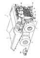
- FIG. 1 is a perspective view showing a schematic configuration of a dump truck according to an embodiment of the present invention.
- FIG. 2 is a diagram illustrating an internal configuration of the driver's seat.
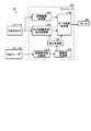
- FIG. 3 is a block diagram illustrating a configuration of the periphery monitoring device.
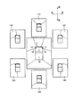
- FIG. 4 is a diagram illustrating an arrangement position of each camera provided in the dump truck.
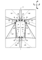
- FIG. 5 is a diagram illustrating an imaging range of each camera.
- FIG. 6 is a diagram illustrating an arrangement position of each radar provided in the dump truck.
- FIG. 7 is a diagram illustrating a detection range of each radar.
- FIG. 8 is a diagram showing a specific arrangement of radars that detect the front of the vehicle.
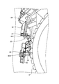
- FIG. 9 is a diagram showing a specific arrangement of radars that detect the left side of the vehicle.
- FIG. 1 is a perspective view showing a schematic configuration of a dump truck according to an embodiment of the present invention.
- FIG. 2 is a diagram illustrating an internal configuration of the driver's
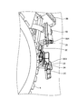
- FIG. 10 is a diagram showing a specific arrangement of radars that detect the right side of the vehicle.
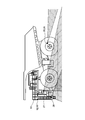
- FIG. 11 is a diagram showing a specific arrangement of radars that detect the rear of the vehicle.
- FIG. 12 is a diagram illustrating the irradiation state of the left side surface of the vehicle and the radar.
- FIG. 13 is a diagram illustrating the rear of the vehicle and the irradiation state of the radar.
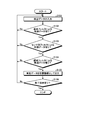
- FIG. 14 is a flowchart illustrating an obstacle detection processing procedure based on radar detection data.
- FIG. 15 is a perspective view showing an example of a protective member for protecting the radar.
- FIG. 16 is a side view showing another example of a protective member for protecting the radar.
- FIG. 17 is a diagram illustrating another arrangement example of the radar that detects the rear of the vehicle.
- front and rear are defined as “front” in a direction based on the direction toward the front of the cab, and the opposite direction is “rear”.
- Left and right refer to the respective directions with reference to the vehicle center plane C, which will be described later, and the direction toward the “front” direction.
- FIG. 1 is a perspective view showing a schematic configuration of a dump truck according to an embodiment of the present invention.
- the dump truck 1 is a super-large vehicle for work used for mining work or the like, and has a vehicle width exceeding 9 m.
- the size of the dump truck 1 can be easily understood by comparing with the pickup truck 300 shown in FIG.
- the dump truck 1 mainly includes a body frame 2, a cab 3, a pair of left and right front wheels 5, a pair of left and right rear wheels 6 that form a pair, a base 7 on which a pantograph for power feeding is installed, and a surrounding monitoring device 10 (see FIG. 3).
- the body frame 2 supports a power mechanism such as a diesel engine and a transmission, and other auxiliary machines. Further, the body frame 2 supports a pair of left and right front wheels 5 at the front portion, and supports a pair of left and right rear wheels 6 at the rear portion of the vehicle.
- the vehicle body frame 2 has a lower deck 2A provided on the front side and near the ground, and an upper deck 2B provided above the lower deck 2A.
- a pair of movable ladders 2C for getting on and off is provided between the lower deck 2A and the ground. Between the lower deck 2A and the upper deck 2B, there is provided an oblique ladder 2D for going back and forth between the lower deck 2A and the upper deck 2B.
- a front fender 2E extending from the lower deck 2A to the upper deck 2B is disposed near the front wheel 5.
- the cab 3 is arranged on the left side on the upper deck 2B. As shown in FIG. 2, the cab 3 forms a protection structure at the time of the fall by four columns 3 a, 3 b, 3 c, 3 d.
- the cab 3 there are a driver's seat 31, a handle 32, a dash cover 33, a radio device 34, a radio receiver 35, a retarder 36, a shift lever 37, a controller 100 (see FIG. 3), a monitor 50, an accelerator pedal, a brake pedal, and the like. Is provided.
- the vessel 4 is a loading platform for loading heavy objects such as crushed stone, and is pivotally connected to the rear end portion of the vehicle body frame 2 via a pivot shaft at the rear bottom.
- the actuator such as a hydraulic cylinder
- the vessel 4 is rotated with the rotation axis as a reference, the front portion of the vessel 4 is raised and the load is discharged, and as shown in FIG. It can be rotated within the range of the loading posture located at the top.
- the periphery monitoring device 10 includes six cameras 11 to 16 arranged around the dump truck 1, eight radars 21 to 28 arranged around the dump truck 1, and a monitor 50.
- the controller 100 is included.
- the controller 100 uses the cameras 11 to 16 to display the presence or absence of obstacles such as automobiles around the dump truck 1 as an overhead image so that the driver can monitor. The driver can be warned of the presence of obstacles.
- the controller 100 includes an overhead image synthesis unit 110, a camera image switching / viewpoint conversion unit 120, a display control unit 130, a monitor image generation unit 140, an obstacle information collection unit 210, and an obstacle processing unit 220. Have.
- the overhead image synthesis unit 110 is connected to the cameras 11 to 16 and receives the image data acquired by the cameras 11 to 16.
- the overhead image synthesis unit 110 synthesizes images corresponding to the plurality of received image data, and generates an overhead image including the entire periphery of the dump truck 1.
- the overhead image synthesis unit 110 generates overhead image data indicating an overhead image obtained by projecting a plurality of images on a predetermined projection plane by performing coordinate conversion on each of the plurality of image data.
- the camera image switching / viewpoint conversion unit 120 is connected to the cameras 11 to 16 and is imaged by the cameras 11 to 16 displayed on the screen of the monitor 50 together with the bird's-eye view image based on the obstacle detection results by the radars 21 to 28. Switch images.
- the camera image switching / viewpoint conversion unit 120 converts captured images acquired by the cameras 11 to 16 into viewpoint images from infinity above the dump truck.
- the display control unit 130 is connected to the camera image switching / viewpoint conversion unit 120, the monitor image generation unit 140, and the obstacle processing unit 220.
- the display control unit 130 synthesizes images acquired by the cameras 11 to 16. Obstacle position data for combining and displaying obstacle position information acquired by the radars 21 to 28 in the bird's-eye view image formed by the bird's-eye view image synthesis unit 110 is displayed in the camera image switching / viewpoint conversion unit 120 and the monitor.
- the image is sent to the image generation unit 140.
- the monitor image generation unit 140 is connected to the overhead image synthesis unit 110, the camera image switching / viewpoint conversion unit 120, and the display control unit 130.
- the monitor image generation unit 140 is an image including the position of the obstacle on the overhead image based on the image data and the obstacle position data of the entire circumference of the dump truck acquired by the cameras 11 to 16 and the radars 21 to 28. Is generated and sent to the monitor 50.
- the monitor 50 displays the obstacle in the display area, so that the driver can recognize the presence of the obstacle.
- the obstacle information collecting unit 210 is connected to the radars 21 to 28 and the obstacle processing unit 220.
- the obstacle information collection unit 210 receives the obstacle detection results detected by the radars 21 to 28 and sends them to the obstacle processing unit 220.
- the obstacle processing unit 220 is connected to the obstacle information collecting unit 210 and the display control unit 130.
- the obstacle processing unit 220 performs processing to exclude the position information of the obstacle received from the obstacle information collecting unit 210 according to the setting, and sends the excluded position information to the display control unit 130. .
- each of the cameras 11 to 16 is attached to the outer peripheral portion of the dump truck 1 in order to acquire an image in the range of 360 degrees around the dump truck 1.
- Each of the cameras 11 to 16 has a visual field range of 120 degrees in the left / right (horizontal) direction and 96 degrees in the height (vertical) direction.
- the camera 11 is a camera that images the front of the vehicle, and is arranged at the lower part of the uppermost landing part of the diagonal ladder 2D as shown in FIG.
- the camera 11 is fixed toward the front of the vehicle via a bracket attached to the upper deck 2B.
- the imaging range of the camera 11 is an imaging range 11C that extends in front of the vehicle in the ground-based imaging area shown in FIG.
- the camera 12 is a camera that captures an image of the right front side of the vehicle, and is disposed near the right end portion of the front side surface of the upper deck 2B as shown in FIG.
- the camera 12 is fixed toward the vehicle right diagonally forward via a bracket attached to the upper deck 2B.
- the imaging range of the camera 12 is an imaging range 12C that extends obliquely forward to the right of the vehicle in the ground-based imaging area shown in FIG.
- the camera 13 is a camera that images the left front side of the vehicle. As shown in FIG. 4, the camera 13 is located symmetrically with the camera 12, that is, the front left side of the vehicle via a bracket attached to the upper deck 2B. It is fixed toward.
- the imaging range of the camera 13 is an imaging range 13C that extends diagonally to the left of the vehicle in the ground-based imaging area shown in FIG.
- the camera 14 is a camera that captures an image of the right rear side of the vehicle, and is disposed in the vicinity of the front end portion of the right side surface of the upper deck 2B as shown in FIG.
- the camera 14 is fixed toward the vehicle right diagonally backward via a bracket attached to the upper deck 2B.
- the imaging range of the camera 14 is an imaging range 14C that extends obliquely rearward to the right of the vehicle in the ground-based imaging area shown in FIG.
- the camera 15 is a camera that captures an image of the left rear side of the vehicle, and as shown in FIG.
- the camera 15 is arranged obliquely rearward on the left side of the vehicle via a bracket attached to the upper deck 2B.
- the imaging range of the camera 15 is an imaging range 15C that extends diagonally to the left rear of the vehicle in the ground-based imaging area shown in FIG.
- the camera 16 is a camera that captures the rear of the vehicle. As shown in FIG. 4, the camera 16 is located at the rear end of the vehicle body frame 2, above the rear axle that connects the two rear wheels 6, and around the vessel 4. It arrange
- the imaging range of the camera 16 is an imaging range 16C that spreads behind the vehicle in the ground-based imaging area shown in FIG.
- each of the cameras 11 to 16 sends a captured image to the controller 100.
- the cameras 11 to 16 are provided on the upper deck 2B and the cross member at a high position of the vehicle body frame. For this reason, it is possible to obtain a captured image looking down on the ground from above with the cameras 11 to 16, and it is possible to capture an obstacle existing on the ground over a wide range. In addition, even when the viewpoint conversion is performed when the overhead image is formed, since the image captured from above is used, the degree of deformation of the three-dimensional object can be suppressed.
- the radars 21 to 28 have a detection angle of 80 degrees ( ⁇ 40 degrees) in the azimuth (horizontal) direction, 16 degrees ( ⁇ 8 degrees) in the vertical (vertical) direction, and a UWB (Ultra Wide) with a maximum detection distance of 15 m or more.
- Band Ultra-wideband
- the relative positions of obstacles existing all around the dump truck 1 are detected by the installed radars 21 to 28.
- the radars 21 to 28 are arranged on the outer periphery of the dump truck 1.
- the detection angle in the azimuth (horizontal) direction of each of the radars 21 to 28 is 80 degrees ( ⁇ 40 degrees), but may have a detection angle larger than this.
- the radars 21 and 22 will be described with reference to FIG. 6 and FIG. 8 of the front view of the dump truck 1.
- the radars 21 and 22 are provided on the lower deck 2A and below the ladder 2D, which are about 1 m above the ground and located below the upper deck 2B in which the camera 11 that mainly captures the front of the vehicle is provided.
- Radars 21 and 22 are mounted symmetrically with respect to vehicle center plane C via brackets B21 and B22, respectively.
- the radar 21 is disposed so as to be directed diagonally forward left
- the radar 22 is disposed so as to be directed diagonally forward right. Specifically, as shown in FIG.
- the irradiation center axis C21 in the horizontal direction of the radar 21 is inclined 45 degrees to the left side of the vehicle with respect to the traveling direction axis of the vehicle center plane C, and the horizontal direction of the radar 22
- the irradiation center axis C22 is inclined 45 degrees to the right side of the vehicle with respect to the traveling direction axis of the vehicle center plane C, and the irradiation center axes C21 and C22 intersect each other.
- each irradiation center axis in the vertical direction of the radars 21 and 22 has a depression angle of about 5 degrees. Thereby, it is possible to detect all obstacles in the front area from the front end of the vehicle.
- the radar 28 and the radar 23 located symmetrically with the vehicle center plane C are shown in FIG. 6, FIG. 9 as viewed from the left side of the dump truck 1, and FIG. 10 as viewed from the right side of the dump truck 1.
- the description will be given with reference.
- the radar 28 is provided in the vicinity of the left end portion of the lower deck 2A and the upper end portion of the ladder 2C, which are located below the upper deck 2B provided with the cameras 13 and 15 that mainly image the left side of the vehicle.
- the radar 28 is attached to the lower deck 2A via a bracket B28, and is disposed toward the left outer side of the vehicle.
- the radar 23 is installed in a side view from the left side of the dump truck 1 and is located symmetrically with the radar 28 with respect to the vehicle center plane C.
- the radar 23 is provided on a ladder 2C provided on the right side of the lower deck 2A, which is located below the upper deck 2B provided with the cameras 12 and 14 that mainly capture the right side of the vehicle, and on the right side of the vehicle.
- the radar 23 is attached to the lower deck 2A via a bracket B23 which is provided symmetrically with respect to the bracket B28 and the vehicle center plane C, and is disposed toward the vehicle right side outward.
- each irradiation central axis in the vertical direction of the radars 23 and 28 has a depression angle of about 5 degrees.
- Radars 23 and 28 enable detection of obstacles on the side of the dump truck 1, particularly on the front side of the front wheels 5 and the rear wheels 6.
- the radars 23 and 28 are located below the vessel 4 and the upper deck 2B, and are not affected by flying stones that jump out of the vessel 4 when loaded.
- FIG. 6 is a side view from the left side of the dump truck 1
- FIG. 10 is a side view from the right side of the dump truck 1.
- the radar 27 is provided at a position projecting sideways from the front fender 2E on the left side of the vehicle extending toward the lower deck 2A located below the upper deck 2B on which the cameras 13 and 15 for imaging the left side of the vehicle are provided.
- the air cleaner 62 is disposed at the side end portion.
- the radar 27 is attached to the front fender 2E with the bracket B27 facing rearward.
- the height of the radar 27 is about 2.5 m from the ground.
- the radar 24 is installed in a side view from the left side of the dump truck 1 and is positioned symmetrically with respect to the radar 27 with respect to the vehicle center plane C.
- the radar 24 is extended to the right side from the front fender 2E on the right side of the vehicle extending toward the lower deck 2A located below the upper deck 2B on which the cameras 12 and 14 for imaging the right side of the vehicle are provided. It arrange
- the radar 24 is attached to the front fender 2E with the bracket B24 facing rearward.
- the horizontal irradiation center axis C24 of the radar 24 is inclined 30 degrees to the right side of the vehicle with respect to the backward axis of the vehicle central plane C, and the horizontal irradiation central axis C27 of the radar 27 is aligned with the vehicle central plane C. It is tilted 30 degrees to the left side of the vehicle with respect to the axis in the reverse direction. Note that these angles are not limited to 30 degrees and may be 45 degrees or less. That is, the rear limit lines L24 and L27 of the horizontal detection range may be directed toward the vehicle center plane C, and the irradiation area may be at an angle that forms the vehicle area E1 including the front wheels 5 and the rear wheels 6.
- the irradiation center axes C24 and C27 preferably cross the front wheel 5 and are directed to the ground contact portion of the rear wheel 6. Further, each irradiation central axis in the vertical direction of the radars 24 and 27 has a depression angle of about 15 degrees.
- the radars 24 and 27 enable detection of obstacles in the lateral rear region corresponding to the rear side of the central axis of the front wheel 5 and the rear wheel 6 on the side of the dump truck 1 and particularly corresponding to the entire region of the side of the vessel.
- the radars 24 and 27 are located below the vessel 4 and the upper deck 2B, and are not affected by flying stones that jump out of the vessel 4 when loaded.
- the lateral detection ranges in the horizontal direction of the radars 23 and 24 and the lateral detection ranges in the horizontal direction of the radars 27 and 28 have overlapping portions, and the radars 23, 24, 27, and 28 Obstacles in the areas on both sides between the front end and the rear end of the vehicle can be detected.
- the radars 23 and 24 arranged on the right side of the vehicle which are symmetrical positions on the left side of the vehicle on which the cab 3 is installed, can detect obstacles on the right side of the vehicle that are difficult to see from the cab 3. .
- the radars 25 and 26 will be described with reference to FIG. 6 and FIG. 11 which is a rear view of the dump truck 1.
- the radars 25 and 26 are about 2 m above the ground, and are arranged on the rear side of the case of the rear axle 71 of the drive shaft of the rear wheel 6 located below the cross member 70 where the camera 16 of the vessel 4 is installed. Is done.
- Radars 25 and 26 are mounted symmetrically with respect to vehicle center plane C via brackets B25 and B26, respectively.
- the radars 25 and 26 are provided between the joints 73 of the rear suspension cylinder 72.
- the radar 25 is disposed so as to be directed rearward and obliquely to the right, and the radar 26 is disposed so as to be directed rearward and obliquely to the left.
- each irradiation central axis in the vertical direction of the radars 25 and 26 has a depression angle of 0 to 10 degrees in the depression direction, and about 5 degrees in this embodiment.
- the radars 25 and 26 are mounted symmetrically with respect to the vehicle center plane C and are installed so that the respective irradiation center axes intersect with each other, so that all the obstacles in the rear area from the rear end of the vehicle are detected. Can do.
- the radars 25 and 26 are arranged with a small depression angle in the case of the rear axle 71 that is positioned lower than the cross member 70. As shown in FIGS. 12 and 13, obstacles hidden far away from the vehicle and behind the vessel 4 can be detected at the same time by the radars 25 and 26 installed in a low position of the vehicle with a small depression angle.
- the horizontal irradiation center axis C25 of the radar 25 and the horizontal irradiation center axis C26 of the radar 26 are 45 degrees with respect to the vehicle center plane C, but may be 45 degrees or less, for example, 30 degrees. It may be. This value may be determined by the degree of rearward protrusion of the radars 25 and 26 with respect to the rear end of the wheel 6.
- Radars 21 to 28 that detect obstacles in each direction of the vehicle are attached to members at positions lower than the cameras 11 to 16 that capture the direction of each vehicle in order to generate an overhead image. Even if a radar having a small angle in the vertical direction is used, obstacle information detected by the radar can be displayed in the overhead view image even in an overhead view image captured and generated by the radar installed at a position lower than the camera. Is possible.
- the obstacle processing unit 220 inputs radar detection data of a predetermined number of scans for each of the radars 21 to 28 from the obstacle information collecting unit 210 (step S101). Thereafter, it is determined whether or not there is valid data for the radar detection data using a basic filter (step S102).
- This basic filter pre-processing filter
- This basic filter has an effective detection range indicating the size of an automobile within a radar detection range (effective scanning angle and effective distance), for example, and has a minimum predetermined reflected signal intensity. Output as valid data.
- step S102 If there is valid data by the basic filter (step S102, Yes), it is further determined from this valid data whether there is valid data to be validated by the sensor-specific filter (step S103).
- This sensor-specific filter performs filtering based on the specifications of the radars 21 to 28. The radar detection range is divided into several areas corresponding to the radar detection capability, and the conditions for each area are satisfied. Data to be output as valid data. This is because the reflected signal has a lower intensity in a far region, a poor time resolution in a near region, and the detection capability may vary depending on the scanning angle.
- step S104 If there is valid data that is valid for the sensor-specific filter (step S103, Yes), it is further determined from the valid data whether there is valid data that is valid for the region filter (step S104). .
- the area filter deletes effective data in the vehicle area when there is a preset vehicle area indicating the inside of the vehicle in the effective data determined to be effective by the sensor-specific filter.
- step S104 If there is valid data to be validated by the area filter (step S104, Yes), this valid data is output as position information to the display control unit 130 (step S105). Thereafter, it is determined whether or not there is an instruction to end the process in the controller 100 (step S106). If there is an instruction to end (step S106, Yes), the process ends. In addition, when there is no valid data by a basic filter (step S102, No), when there is no valid data which a filter according to a sensor validates (step S103, No), there is no valid data which a region filter validates (step S104). , No) and when there is no end instruction (step S106, No), the process proceeds to step S101 and the above-described processing is repeated.
- the obstacle processing unit 220 deletes the valid data in the vehicle area by the area filter. For example, of the obstacle information detected by the radars 24 and 27, the obstacle information of the vehicle area E1 shown in FIG. 7 is deleted by the area filter as not being valid data. As a result, the obstacle information in the vehicle area E1 is not sent to the monitor 50 via the display control unit 130 and the monitor image generation unit 140, so the obstacle information in the vehicle area E1 is displayed on the display screen of the monitor 50. Not.
- the radars 25 and 26 are installed at an angle so as to intersect the vehicle center plane C, but the rear suspension cylinder 72 is detected depending on the angle.
- the area filter of the obstacle processing unit 220 deletes the obstacle information of the vehicle area. Therefore, the rear suspension cylinder 72 is displayed on the monitor 50. It is not displayed on the screen.
- radar detection data acquired by the radars 21 to 28 may include ground information. Therefore, the obstacle processing unit 220 presets an area below the vehicle installation surface as a deletion area similar to the vehicle area, and uses the area filter to obtain radar detection data on the ground that is below a predetermined height in consideration of rutting and the like. It is preferable to delete.
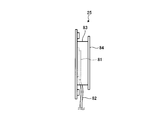
- Each of the radars 21 to 28 is provided with a protective member 83 that is a hood surrounding the radar main body 81, like the radar 25 shown in FIGS.
- the protective member 83 has a cutout portion where the cable 82 is pulled out.
- a protective member 84 may be provided to cover the opening in the space surrounded by the protective member 83, that is, the irradiation side opening.
- This protection member 84 protects the front surface and has strength, but it is necessary that the protection member 84 be a member through which a radar signal is transmitted. Moreover, it is preferable that it is a transparent member. This is because if it is transparent, condensation on the surface of the radar main body 81 can be visually confirmed.
- the protective member 84 is formed of, for example, polycarbonate.
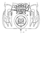
- the present invention is not limited to this.
- a radar 80 that is close to 180 degrees and wide in the horizontal direction, as shown in FIG. One may be provided at the center of the rear axle 71 and between the joints of the rear suspension cylinder. In this case, even if a radar having a small angle in the vertical direction is used, it is possible to detect an obstacle far from the vehicle by installing the radar at a low position of the vehicle.
- a pair of left and right radars are described. However, the arrangement of the radars does not have to be a pair of left and right as long as it is an arrangement for enabling obstacle detection.
- the above-described dump truck is also applied to a dump truck in an unmanned dump truck operation system that is wirelessly managed.
- the collision prevention control is performed by an emergency stop or the like.
Abstract
Description
図1は、この発明の実施の形態であるダンプトラックの概要構成を示す斜視図である。図1に示すように、ダンプトラック1は、鉱山作業などに用いられる作業用の超大型車両であって、9mを超える車幅を有する。このダンプトラック1の大きさは、図1に示したピックアップトラック300と比較することによって理解しやすい。ダンプトラック1は、主として、車体フレーム2、キャブ3、左右一対の前輪5および左右各々が2輪1組となり左右一対をなす後輪6、給電用のパンタグラフを設置するベース7、および周辺監視装置10(図3参照)を有する。
図3に示すように、周辺監視装置10は、ダンプトラック1の周囲に配置された6台のカメラ11~16、ダンプトラック1の周囲に配置された8台のレーダ21~28、モニタ50と、コントローラ100を有する。
各カメラ11~16は、図4に示すように、ダンプトラック1の周囲360度の範囲の画像を取得するために、ダンプトラック1の外周部分にそれぞれ取り付けられる。各カメラ11~16は、左右(水平)方向に120度、高さ(垂直)方向に96度の視野範囲を有する。
レーダ21~28は、方位(水平)方向80度(±40度)、上下(垂直)方向16度(±8度)の検出角度を有し、検出距離が最大15m以上のUWB(Ultra Wide
Band:超広帯域)レーダである。設置されるレーダ21~28により、ダンプトラック1の全周囲に存在する障害物の相対位置を検出する。各レーダ21~28は、ダンプトラック1の外周部分に配置される。なお、各レーダ21~28の方位(水平)方向の検出角度は、80度(±40度)としているが、これ以上の検出角度を有していてもよい。
レーダ28および車両中心面Cの対称の位置にあるレーダ23を、図6、ダンプトラック1の左側から側方視となる図9、およびダンプトラック1の右側からの側方視となる図10を参照して説明する。レーダ28は、主に車両の左側側方を撮像するカメラ13,15が備えられるアッパデッキ2Bの下方に位置するロアデッキ2Aの左側端部、ラダー2C上端部近傍に設けられる。レーダ28は、ロアデッキ2AにブラケットB28を介し取り付けられ、車両左側側方外側に向けて配置される。
ここで、図14に示したフローチャートを参照して、レーダ21~28の検出データに基づいた障害物検出処理手順について説明する。まず、障害物処理部220は、各レーダ21~28ごとの所定走査数のレーダ検出データを障害物情報収集部210から入力する(ステップS101)。その後、このレーダ検出データに対して、基本フィルタを用いて有効データがあるか否かを判断する(ステップS102)。この基本フィルタ(前処理フィルタ)は、例えばレーダ検出範囲(有効走査角および有効距離)内で、自動車程度の大きさを示す有効検出範囲を有し、かつ、最低限の所定反射信号強度を有するものを有効データとして出力する。
2 車体フレーム
2A ロアデッキ
2B アッパデッキ
2C,2D ラダー
2E フロントフェンダー
3 キャブ
3a~3d 支柱
4 ベッセル
5 前輪
6 後輪
7 ベース
10 周辺監視装置
11~16 カメラ
21~28,80 レーダ
31 運転席
32 ハンドル
33 ダッシュカバー
34 無線装置
35 ラジオ受信機
36 リターダ
37 シフトレバー
50 モニタ
62 エアークリーナ
70 クロスメンバー
71 リアアクスル
72 リアサスペンションシリンダ
73 接合部
100 コントローラ
110 俯瞰画像合成部
120 カメラ画像切替・視点変換部
130 表示制御部
140 モニタ画像生成部
210 障害物情報収集部
220 障害物処理部
300 ピックアップトラック
B21,B22,B25,B26,B27,B28 ブラケット
C 車両中心面
C21~C28 照射中心軸
E1 車両領域
L24,L27 後方側限界線
Claims (5)
- 車両周囲に設けた複数のレーダを用いて車両周囲の障害物を検出することができる障害物検出機構付きダンプトラックであって、
リアアクスルケースの後方側、かつ、リアサスペンションシリンダとの接合部間に、車両中心面に対して配置されたレーダを設け、垂直方向の照射中心軸が所定の俯角を持つように配置されて車両後方の障害物を検出することを特徴とする障害物検出機構付きダンプトラック。 - 前記レーダは、リアアクスルケースの中心面に対して左右対称に配置された一対のレーダからなり、一対のレーダから照射される照射中心軸は、車両中心面で交差することを特徴とする請求項1に記載の障害物検出機構付きダンプトラック。
- 前記一対のレーダを含む複数のレーダは、該レーダの取付周囲に該レーダを保護する保護部材に囲まれることを特徴とする請求項2に記載の障害物検出機構付きダンプトラック。
- 前記保護部材は、照射方向前方面に照射信号が透過するカバーを有することを特徴とする請求項3に記載の障害物検出機構付きダンプトラック。
- 車両周囲に設けた複数のレーダを用いて車両周囲の障害物を検出することができる障害物検出機構付きダンプトラックの障害物検出方法であって、
リアアクスルケースの後方側、かつ、リアサスペンションシリンダとの接合部間に、車両中心面に対して配置され、垂直方向の照射中心軸が所定の俯角を持つように配置されて車両後方の障害物を検出するレーダが検出する障害物情報のうち、車両自体を示す予め設定された車両領域内の障害物情報を除外することを特徴とする障害物検出機構付きダンプトラックの障害物検出方法。
Priority Applications (4)
| Application Number | Priority Date | Filing Date | Title |
|---|---|---|---|
| CN2012800029530A CN103415783A (zh) | 2012-03-15 | 2012-09-19 | 带有障碍物检测机构的自卸车及其障碍物检测方法 |
| AU2012372153A AU2012372153A1 (en) | 2012-03-15 | 2012-09-19 | Dump truck with obstacle detection mechanism and obstacle detection method thereof |
| US13/824,505 US20140266859A1 (en) | 2012-03-15 | 2012-09-19 | Dump truck with obstacle detection mechanism and method for detecting obstacle |
| CA2809654A CA2809654C (en) | 2012-03-15 | 2012-09-19 | Dump truck with obstacle detection mechanism and method for detecting obstacle |
Applications Claiming Priority (2)
| Application Number | Priority Date | Filing Date | Title |
|---|---|---|---|
| JP2012-059416 | 2012-03-15 | ||
| JP2012059416A JP2013195086A (ja) | 2012-03-15 | 2012-03-15 | 障害物検出機構付きダンプトラック |
Publications (1)
| Publication Number | Publication Date |
|---|---|
| WO2013136566A1 true WO2013136566A1 (ja) | 2013-09-19 |
Family
ID=49160521
Family Applications (1)
| Application Number | Title | Priority Date | Filing Date |
|---|---|---|---|
| PCT/JP2012/073951 WO2013136566A1 (ja) | 2012-03-15 | 2012-09-19 | 障害物検出機構付きダンプトラックおよびその障害物検出方法 |
Country Status (6)
| Country | Link |
|---|---|
| US (1) | US20140266859A1 (ja) |
| JP (1) | JP2013195086A (ja) |
| CN (1) | CN103415783A (ja) |
| AU (1) | AU2012372153A1 (ja) |
| CA (1) | CA2809654C (ja) |
| WO (1) | WO2013136566A1 (ja) |
Cited By (2)
| Publication number | Priority date | Publication date | Assignee | Title |
|---|---|---|---|---|
| CN108859942A (zh) * | 2018-05-21 | 2018-11-23 | 苏州工业园区职业技术学院 | 一种自卸车的举升控制系统 |
| CN111133491A (zh) * | 2017-11-10 | 2020-05-08 | 株式会社小松制作所 | 自卸卡车 |
Families Citing this family (17)
| Publication number | Priority date | Publication date | Assignee | Title |
|---|---|---|---|---|
| JP5667594B2 (ja) * | 2012-03-15 | 2015-02-12 | 株式会社小松製作所 | 障害物検出機構付きダンプトラックおよびその障害物検出方法 |
| US9428334B2 (en) * | 2013-05-17 | 2016-08-30 | The Heil Co. | Automatic control of a refuse front end loader |
| JP6284741B2 (ja) * | 2013-10-24 | 2018-02-28 | 日立建機株式会社 | 後退支援装置 |
| US10228701B2 (en) | 2013-12-27 | 2019-03-12 | Komatsu Ltd. | Mining machine management system and management method |
| US10168425B2 (en) * | 2014-07-03 | 2019-01-01 | GM Global Technology Operations LLC | Centralized vehicle radar methods and systems |
| JP6010634B2 (ja) * | 2014-09-01 | 2016-10-19 | 株式会社小松製作所 | 運搬車両、ダンプトラック、及び運搬車両の制御方法 |
| JP6315696B2 (ja) * | 2014-09-29 | 2018-04-25 | 日立建機株式会社 | 運搬車両の停止位置算出装置 |
| US9989636B2 (en) | 2015-03-26 | 2018-06-05 | Deere & Company | Multi-use detection system for work vehicle |
| JP6580982B2 (ja) * | 2015-12-25 | 2019-09-25 | 日立建機株式会社 | オフロードダンプトラック及び障害物判別装置 |
| JP6754594B2 (ja) * | 2016-03-23 | 2020-09-16 | 株式会社小松製作所 | モータグレーダ |
| JP6666180B2 (ja) | 2016-03-23 | 2020-03-13 | 株式会社小松製作所 | モータグレーダの制御方法およびモータグレーダ |
| AU2016248873B2 (en) * | 2016-04-28 | 2018-01-04 | Komatsu Ltd. | Work machine management apparatus |
| CN107015219A (zh) * | 2017-03-27 | 2017-08-04 | 上海斐讯数据通信技术有限公司 | 具有雷达成像功能的防碰撞方法及其系统 |
| WO2018151335A1 (ja) * | 2018-03-12 | 2018-08-23 | 株式会社小松製作所 | ダンプトラック |
| US11320830B2 (en) | 2019-10-28 | 2022-05-03 | Deere & Company | Probabilistic decision support for obstacle detection and classification in a working area |
| US11768289B2 (en) | 2021-05-24 | 2023-09-26 | Caterpillar Paving Products Inc. | Work machine with LiDAR having reduced false object detection |
| JP7374276B1 (ja) | 2022-09-28 | 2023-11-06 | 日立建機株式会社 | ダンプトラック |
Family Cites Families (18)
| Publication number | Priority date | Publication date | Assignee | Title |
|---|---|---|---|---|
| JPH0321501Y2 (ja) * | 1985-09-06 | 1991-05-10 | ||
| US7209221B2 (en) * | 1994-05-23 | 2007-04-24 | Automotive Technologies International, Inc. | Method for obtaining and displaying information about objects in a vehicular blind spot |
| US8041483B2 (en) * | 1994-05-23 | 2011-10-18 | Automotive Technologies International, Inc. | Exterior airbag deployment techniques |
| JPH09211113A (ja) * | 1996-01-31 | 1997-08-15 | Komatsu Ltd | ミリ波レーダ搭載車両 |
| US6292725B1 (en) * | 1997-04-04 | 2001-09-18 | Komatsu Ltd. | Interference preventing device for vehicle |
| DE19805515A1 (de) * | 1998-02-11 | 1999-08-12 | Bayerische Motoren Werke Ag | Hinderniserkennungssystem in einem Kraftfahrzeug |
| US7852462B2 (en) * | 2000-05-08 | 2010-12-14 | Automotive Technologies International, Inc. | Vehicular component control methods based on blind spot monitoring |
| JP3865121B2 (ja) * | 2001-10-31 | 2007-01-10 | 株式会社小松製作所 | 車両の障害物検出装置 |
| US6861972B2 (en) * | 2003-07-28 | 2005-03-01 | Ellistar Sensor Systems, Inc. | Object detection apparatus and method |
| FR2913775B1 (fr) * | 2007-03-16 | 2010-08-13 | Thales Sa | Systeme de detection d'obstacle notamment pour un systeme d'anticollision |
| US8280621B2 (en) * | 2008-04-15 | 2012-10-02 | Caterpillar Inc. | Vehicle collision avoidance system |
| US8170787B2 (en) * | 2008-04-15 | 2012-05-01 | Caterpillar Inc. | Vehicle collision avoidance system |
| US20090259399A1 (en) * | 2008-04-15 | 2009-10-15 | Caterpillar Inc. | Obstacle detection method and system |
| US8473173B1 (en) * | 2008-09-08 | 2013-06-25 | William Robles | Motion sensor braking system and associated method |
| JP2010197378A (ja) * | 2009-01-14 | 2010-09-09 | Mitsubishi Electric Corp | レーダ画像処理装置 |
| WO2010097839A1 (ja) * | 2009-02-27 | 2010-09-02 | トヨタ自動車株式会社 | 車載レーダー装置および車載レーダー装置用カバー |
| JP4881984B2 (ja) * | 2009-08-28 | 2012-02-22 | 株式会社ファルテック | レドームの製造方法 |
| DE102010012626A1 (de) * | 2010-03-24 | 2011-09-29 | Valeo Schalter Und Sensoren Gmbh | Kraftfahrzeug mit einer Radareinrichtung und Verfahren zum Betreiben einer Radareinrichtung |
-
2012
- 2012-03-15 JP JP2012059416A patent/JP2013195086A/ja active Pending
- 2012-09-19 US US13/824,505 patent/US20140266859A1/en not_active Abandoned
- 2012-09-19 WO PCT/JP2012/073951 patent/WO2013136566A1/ja active Application Filing
- 2012-09-19 CN CN2012800029530A patent/CN103415783A/zh active Pending
- 2012-09-19 CA CA2809654A patent/CA2809654C/en not_active Expired - Fee Related
- 2012-09-19 AU AU2012372153A patent/AU2012372153A1/en not_active Abandoned
Non-Patent Citations (2)
| Title |
|---|
| KODO JOHOKA KENSETSU KIKAI ET AL.: "Japan Patent Office", Retrieved from the Internet <URL:http://www.jpo.go.jp/shiryou/s_sonota/hyoujun_gijutsu.htm> [retrieved on 20040326] * |
| TODD RUFF: "Evaluation of a radar-based proximity warning system for off-highway dump trucks", ACCIDENT ANALYSIS AND PREVENTION, vol. 38, no. ISS.1, January 2006 (2006-01-01), pages 92 - 98 * |
Cited By (3)
| Publication number | Priority date | Publication date | Assignee | Title |
|---|---|---|---|---|
| CN111133491A (zh) * | 2017-11-10 | 2020-05-08 | 株式会社小松制作所 | 自卸卡车 |
| US11485293B2 (en) | 2017-11-10 | 2022-11-01 | Komatsu Ltd. | Dump truck |
| CN108859942A (zh) * | 2018-05-21 | 2018-11-23 | 苏州工业园区职业技术学院 | 一种自卸车的举升控制系统 |
Also Published As
| Publication number | Publication date |
|---|---|
| CN103415783A (zh) | 2013-11-27 |
| CA2809654C (en) | 2017-06-20 |
| AU2012372153A1 (en) | 2013-10-10 |
| JP2013195086A (ja) | 2013-09-30 |
| CA2809654A1 (en) | 2013-09-15 |
| US20140266859A1 (en) | 2014-09-18 |
Similar Documents
| Publication | Publication Date | Title |
|---|---|---|
| JP5667594B2 (ja) | 障害物検出機構付きダンプトラックおよびその障害物検出方法 | |
| WO2013136566A1 (ja) | 障害物検出機構付きダンプトラックおよびその障害物検出方法 | |
| JP5550695B2 (ja) | 作業車両用周辺監視システム及び作業車両 | |
| JP5411976B1 (ja) | 作業車両用周辺監視システム及び作業車両 | |
| JP5324690B1 (ja) | 作業車両用周辺監視システム及び作業車両 | |
| JP5781978B2 (ja) | ダンプトラック | |
| WO2012169359A1 (ja) | ダンプトラック | |
| WO2014045458A1 (ja) | 作業車両用周辺監視システム及び作業車両 | |
| WO2014045456A1 (ja) | 作業車両用周辺監視システム及び作業車両 | |
| WO2014045457A1 (ja) | 作業車両用周辺監視システム及び作業車両 | |
| JP6401141B2 (ja) | 車両周囲障害物検出装置 | |
| JP6012680B2 (ja) | ダンプトラック | |
| JP5788048B2 (ja) | 作業車両用周辺監視システム及び作業車両 | |
| JP5595565B2 (ja) | 作業車両用周辺監視システム、作業車両及び作業車両用周辺監視方法 | |
| CA2815816C (en) | Working vehicle perimeter monitoring system and working vehicle | |
| JP5964353B2 (ja) | ダンプトラック | |
| JP2015029357A (ja) | ダンプトラック用周辺監視システム及びダンプトラック |
Legal Events
| Date | Code | Title | Description |
|---|---|---|---|
| WWE | Wipo information: entry into national phase |
Ref document number: 2809654 Country of ref document: CA |
|
| WWE | Wipo information: entry into national phase |
Ref document number: 13824505 Country of ref document: US |
|
| 121 | Ep: the epo has been informed by wipo that ep was designated in this application |
Ref document number: 12871210 Country of ref document: EP Kind code of ref document: A1 |
|
| NENP | Non-entry into the national phase |
Ref country code: DE |
|
| 122 | Ep: pct application non-entry in european phase |
Ref document number: 12871210 Country of ref document: EP Kind code of ref document: A1 |