WO2013128846A1 - 光音響画像生成装置及び方法 - Google Patents
光音響画像生成装置及び方法 Download PDFInfo
- Publication number
- WO2013128846A1 WO2013128846A1 PCT/JP2013/000929 JP2013000929W WO2013128846A1 WO 2013128846 A1 WO2013128846 A1 WO 2013128846A1 JP 2013000929 W JP2013000929 W JP 2013000929W WO 2013128846 A1 WO2013128846 A1 WO 2013128846A1
- Authority
- WO
- WIPO (PCT)
- Prior art keywords
- spatial frequency
- image data
- photoacoustic
- cross
- light
- Prior art date
Links
Images


Classifications
-
- A—HUMAN NECESSITIES
- A61—MEDICAL OR VETERINARY SCIENCE; HYGIENE
- A61B—DIAGNOSIS; SURGERY; IDENTIFICATION
- A61B5/00—Measuring for diagnostic purposes; Identification of persons
- A61B5/0093—Detecting, measuring or recording by applying one single type of energy and measuring its conversion into another type of energy
- A61B5/0095—Detecting, measuring or recording by applying one single type of energy and measuring its conversion into another type of energy by applying light and detecting acoustic waves, i.e. photoacoustic measurements
-
- A—HUMAN NECESSITIES
- A61—MEDICAL OR VETERINARY SCIENCE; HYGIENE
- A61B—DIAGNOSIS; SURGERY; IDENTIFICATION
- A61B5/00—Measuring for diagnostic purposes; Identification of persons
- A61B5/72—Signal processing specially adapted for physiological signals or for diagnostic purposes
- A61B5/7235—Details of waveform analysis
- A61B5/7253—Details of waveform analysis characterised by using transforms
- A61B5/7257—Details of waveform analysis characterised by using transforms using Fourier transforms
-
- A—HUMAN NECESSITIES
- A61—MEDICAL OR VETERINARY SCIENCE; HYGIENE
- A61B—DIAGNOSIS; SURGERY; IDENTIFICATION
- A61B5/00—Measuring for diagnostic purposes; Identification of persons
- A61B5/74—Details of notification to user or communication with user or patient ; user input means
- A61B5/742—Details of notification to user or communication with user or patient ; user input means using visual displays
-
- A—HUMAN NECESSITIES
- A61—MEDICAL OR VETERINARY SCIENCE; HYGIENE
- A61B—DIAGNOSIS; SURGERY; IDENTIFICATION
- A61B8/00—Diagnosis using ultrasonic, sonic or infrasonic waves
- A61B8/08—Detecting organic movements or changes, e.g. tumours, cysts, swellings
- A61B8/0891—Detecting organic movements or changes, e.g. tumours, cysts, swellings for diagnosis of blood vessels
-
- A—HUMAN NECESSITIES
- A61—MEDICAL OR VETERINARY SCIENCE; HYGIENE
- A61B—DIAGNOSIS; SURGERY; IDENTIFICATION
- A61B8/00—Diagnosis using ultrasonic, sonic or infrasonic waves
- A61B8/52—Devices using data or image processing specially adapted for diagnosis using ultrasonic, sonic or infrasonic waves
- A61B8/5207—Devices using data or image processing specially adapted for diagnosis using ultrasonic, sonic or infrasonic waves involving processing of raw data to produce diagnostic data, e.g. for generating an image
-
- A—HUMAN NECESSITIES
- A61—MEDICAL OR VETERINARY SCIENCE; HYGIENE
- A61B—DIAGNOSIS; SURGERY; IDENTIFICATION
- A61B8/00—Diagnosis using ultrasonic, sonic or infrasonic waves
- A61B8/52—Devices using data or image processing specially adapted for diagnosis using ultrasonic, sonic or infrasonic waves
- A61B8/5215—Devices using data or image processing specially adapted for diagnosis using ultrasonic, sonic or infrasonic waves involving processing of medical diagnostic data
-
- G—PHYSICS
- G16—INFORMATION AND COMMUNICATION TECHNOLOGY [ICT] SPECIALLY ADAPTED FOR SPECIFIC APPLICATION FIELDS
- G16H—HEALTHCARE INFORMATICS, i.e. INFORMATION AND COMMUNICATION TECHNOLOGY [ICT] SPECIALLY ADAPTED FOR THE HANDLING OR PROCESSING OF MEDICAL OR HEALTHCARE DATA
- G16H50/00—ICT specially adapted for medical diagnosis, medical simulation or medical data mining; ICT specially adapted for detecting, monitoring or modelling epidemics or pandemics
- G16H50/20—ICT specially adapted for medical diagnosis, medical simulation or medical data mining; ICT specially adapted for detecting, monitoring or modelling epidemics or pandemics for computer-aided diagnosis, e.g. based on medical expert systems
-
- A—HUMAN NECESSITIES
- A61—MEDICAL OR VETERINARY SCIENCE; HYGIENE
- A61B—DIAGNOSIS; SURGERY; IDENTIFICATION
- A61B2576/00—Medical imaging apparatus involving image processing or analysis
-
- A—HUMAN NECESSITIES
- A61—MEDICAL OR VETERINARY SCIENCE; HYGIENE
- A61B—DIAGNOSIS; SURGERY; IDENTIFICATION
- A61B8/00—Diagnosis using ultrasonic, sonic or infrasonic waves
- A61B8/54—Control of the diagnostic device
Definitions
- the present invention relates to a photoacoustic image generating apparatus and method, and more particularly, to photoacoustic image generation by irradiating a subject with light and detecting an acoustic wave generated in the subject by light irradiation to generate a photoacoustic image.
- Apparatus and method are particularly, to photoacoustic image generation by irradiating a subject with light and detecting an acoustic wave generated in the subject by light irradiation to generate a photoacoustic image.
- Ultrasonography is known as a type of imaging that can noninvasively inspect the internal condition of a living body.
- an ultrasonic probe capable of transmitting and receiving ultrasonic waves is used.
- the ultrasonic waves travel inside the living body and are reflected at the tissue interface.
- the internal appearance can be imaged by calculating the distance based on the time it takes for the ultrasound probe to receive the reflected sound and the reflected ultrasound to return to the ultrasound probe.
- photoacoustic imaging which image-forms the inside of a biological body using a photoacoustic effect is known.
- pulsed laser light is applied to the inside of a living body.
- living tissue absorbs the energy of the pulsed laser light, and adiabatic expansion by the energy generates an ultrasonic wave (photoacoustic signal).
- photoacoustic signal is detected by an ultrasonic probe or the like, and a photoacoustic image is constructed based on the detection signal, whereby visualization in the living body based on the photoacoustic signal is possible.
- Patent Document 1 describes that spatial frequency processing is performed for photoacoustic imaging.
- the irradiation light from a light source is irradiated to a test object, and a photoacoustic signal is detected by several detector elements.
- the detected photoacoustic signal includes the photoacoustic signal generated on the surface of the subject and the photoacoustic signal generated inside the subject.
- the detection signals of a plurality of detector elements at the same reception time are Fourier-transformed in the space direction to acquire a space frequency signal.
- the spatial frequency signal In the spatial frequency signal, components below the predetermined frequency are reduced, the inverse Fourier transform is performed on the spatial frequency signal whose low frequency component is reduced, and a photoacoustic image is generated based on the signal obtained by the inverse transform. Do. Since the photoacoustic signal generated on the surface of the subject is simultaneously obtained by a plurality of detector elements, imaging in which the influence of the photoacoustic wave generated on the surface of the subject is reduced is possible.
- Patent Document 2 discloses that in ultrasonic imaging, image data is subjected to Fourier transform to generate image data in a spatial frequency domain, and predetermined low-frequency components of image data in the Fourier transform spatial frequency domain are generated. It is described that image data in the spatial frequency domain, which has been removed and low-pass components removed, is inversely transformed to generate image data in the actual data area.
- the low-pass component corresponds to shading and the image part necessary for diagnosis does not exist in the low-pass, removing the component with low spatial frequency removes the shading. It is stated that it corresponds to That is, in Patent Document 2, a desired region to be viewed in image data exists in the high region in the spatial frequency region, so low frequency removal is performed in the spatial frequency region so as to remove regions other than the necessary region. There is.
- a blood vessel etc. can be considered as a part imaged by photoacoustic, for example.
- blood vessels of various sizes from thick to thin and it is considered to be useful for diagnostic imaging if blood vessels of a desired size can be imaged therefrom.
- a signal of the same time is Fourier-transformed in the spatial direction with respect to the detection signal of the photoacoustic wave itself, and therefore, a blood vessel of a desired size can not be extracted and imaged.
- Patent Document 2 since the target is an ultrasound image and the region to be viewed is simply present in the high region of the spatial frequency region, only by performing the spatial frequency processing for removing the low frequency component The desired structure can not be extracted and imaged.
- a light source for emitting light to be irradiated to a subject
- an acoustic wave detection means for detecting a photoacoustic wave generated in the subject by light irradiation to the subject
- light Photoacoustic image generation means which reconstructs a photoacoustic signal which is a detection signal of an acoustic wave and generates image data, Fourier transform which Fourier transforms image data in a two or more dimensional space, and generates image data of a spatial frequency domain Means
- spatial frequency processing means for extracting a predetermined spatial frequency component from image data in the spatial frequency domain
- Fourier inverse transformation means for performing inverse Fourier transform on the extracted spatial frequency component to generate image data after spatial frequency processing
- a photoacoustic image generating apparatus characterized by comprising:
- the spatial frequency processing means may extract spatial frequency components higher than the first spatial frequency and lower than the second frequency region higher than the first spatial frequency.
- the first spatial frequency and the second spatial frequency may be changed according to the position in the spatial frequency domain (wave number space).
- the spatial frequency processing means may be configured to determine the predetermined spatial frequency component to be extracted according to the observation target condition designated by the user.
- the image processing apparatus may further include a cross-sectional image generation unit that generates cross-sectional image data in which image data in a predetermined range in the direction along the axis is integrated, and the Fourier transform unit may perform two-dimensional Fourier transform on the cross-sectional image data.
- the cross-sectional image generation unit cuts out cross sections at a plurality of positions along one axis to generate a plurality of cross-sectional image data
- a Fourier transform unit Fourier-transforms each of the plurality of generated cross-sectional image data
- Image data in the spatial frequency domain is generated
- the spatial frequency processing means extracts a predetermined spatial frequency component from each of the plurality of generated image data in the spatial frequency domain
- the inverse Fourier transform means The predetermined spatial frequency components extracted from each of the image data of the area may be subjected to Fourier inverse transform to generate cross-sectional image data after spatial frequency processing for each of the plurality of cross-sectional image data.
- the cross-sectional image generation unit may cut out cross sections at equal intervals.
- the cross-sectional image generation means may cut out the cross section in a direction parallel to the acoustic wave detection surface of the super acoustic wave detection means along an axis corresponding to the depth direction in the object.
- the cross-sectional image generation unit may integrate the image data within the predetermined range by projecting the maximum value of the image data within the predetermined range or integrating the image data within the predetermined range.
- the image display control means is further configured to cause the display device to display cross-sectional image data after spatial frequency processing obtained by performing inverse Fourier transform on predetermined spatial frequency components extracted from cross-sectional image data in the spatial frequency domain. Good.
- the image processing apparatus further comprises cross section position selection means for determining the cross section position of the displayed cross section image data according to the user operation, and the display control means displays the cross section image data subjected to spatial frequency processing corresponding to the cross section position designated by the user. It may be displayed on the device.
- the display control means may display a slide bar for specifying the cross-sectional position on the display device, and the cross-sectional position selection means may determine the cross-sectional position in accordance with the user's operation of the slide bar.
- the display control means may display the cross-sectional image data before the spatial frequency processing and the cross-sectional image data after the spatial frequency processing on the display device side by side.
- the display control means may binarize the cross-sectional image data after spatial frequency processing and display it on the display device.
- the Fourier transform means may three-dimensionally Fourier transform three-dimensional image data based on the three-dimensionally detected photoacoustic wave.
- the light source emits light of a plurality of different wavelengths
- the acoustic wave detection means detects a plurality of photoacoustic waves generated in the subject after each of the plurality of wavelengths of light is irradiated, and the photoacoustic image is generated.
- Generation means respectively reconstructs photoacoustic signals detected corresponding to light of a plurality of wavelengths and image data, and Fourier transform means Fourier-transforms each of image data corresponding to light of a plurality of wavelengths
- the spatial frequency processing means extracts predetermined spatial frequency components corresponding to each wavelength from the image data of the spatial frequency domain corresponding to the light of a plurality of wavelengths which has been subjected to Fourier transform, and the inverse Fourier transform means extracts Each of the processed spatial frequency components may be inverse Fourier transformed.
- a spatial frequency component that the light of a plurality of wavelengths includes the light of the first wavelength and the light of the second wavelength
- the spatial frequency processing means extracts from the image data of the spatial frequency domain corresponding to the light of the first wavelength
- the spatial frequency extracted from the image data of the spatial frequency domain corresponding to the light of the second wavelength may be different from each other.
- composition further provided with the deconvoluting means which deconvolutes the differential waveform of the light irradiated to a subject from a photoacoustic signal.
- the present invention also includes the steps of: irradiating a subject with light from a light source; detecting a photoacoustic wave generated in the subject by light irradiation of the subject; and photoacoustic that is a detection signal of the photoacoustic wave Reconstructing the signal to generate image data, Fourier transforming the image data in a two or more dimensional space, and generating image data in the spatial frequency domain, and predetermined spatial frequency from the image data in the spatial frequency domain
- a photoacoustic image generation method comprising the steps of: extracting components; and performing inverse Fourier transform on the extracted processing spatial frequency components to generate spatial frequency processed image data.
- the photoacoustic image generating apparatus and method according to the present invention Fourier-transforms image data obtained by reconstructing a photoacoustic signal into image data in a spatial frequency domain, and extracts a predetermined spatial frequency component from the image data.
- the extracted spatial frequency component is subjected to inverse Fourier transform to generate image data after spatial frequency processing.
- a desired structure can be selectively imaged by appropriately selecting the spatial frequency component to be extracted according to the size of the observation target and the like.
- FIG. 7 is a view showing cross-sectional image data obtained by performing inverse Fourier transform.
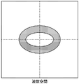
- FIG. 6 shows an elliptical spatial frequency filter.
- FIG. 6 shows a spatial frequency filter that removes low frequency regions.
- FIG. 1 shows a photoacoustic image generation apparatus according to a first embodiment of the present invention.
- the photoacoustic image generation apparatus (photoacoustic image diagnostic apparatus) 10 includes an ultrasound probe (probe) 11, an ultrasound unit 12, and a light source (laser unit) 13.
- the laser unit 13 is a light source and generates light (laser light) to be irradiated to the subject.
- the wavelength of the laser light may be appropriately set according to the object to be observed.
- the laser unit 13 emits, for example, light of a wavelength at which absorption of hemoglobin is large, specifically, a wavelength of 750 nm or 800 nm.
- the laser beam emitted from the laser unit 13 is guided to the probe 11 using a light guiding means such as an optical fiber, for example, and is irradiated onto the subject from the probe 11. Alternatively, light irradiation may be performed from a place other than the probe 11.
- the probe 11 has an acoustic wave detection means for detecting an acoustic wave (ultrasound) from within the subject.
- the probe 11 has, for example, a plurality of ultrasonic transducers arranged in a one-dimensional manner.
- the probe 11 detects a photoacoustic wave (hereinafter also referred to as a photoacoustic signal) generated by the measurement object in the subject absorbing the light from the laser unit 13 with a plurality of ultrasonic transducers.
- the ultrasound unit 12 includes a reception circuit 21, an AD conversion unit 22, a reception memory 23, a photoacoustic image reconstruction unit 24, a detection / logarithmic conversion unit 25, an image construction unit 26, a cross-sectional image generation unit 27, a Fourier transform unit 28,
- the spatial frequency processing means 29, the inverse Fourier transform means 30, the display control means 31, the trigger control circuit 32, and the control means 33 are included.
- the control means 33 controls each part in the ultrasonic unit 12.
- the receiving circuit 21 receives a detection signal (photoacoustic signal) of the photoacoustic wave detected by the probe 11.
- the AD conversion means 22 samples the photoacoustic signal received by the receiving circuit 21 and converts it into a digital signal.
- the AD conversion unit 22 samples the photoacoustic signal at a predetermined sampling period in synchronization with, for example, an AD clock signal.
- the trigger control circuit 32 outputs a light trigger signal for instructing the laser unit 13 to emit light.
- the laser unit 13 includes a flash lamp 41 for exciting a laser medium (not shown) such as YAG or titanium-sapphire, and a Q switch 42 for controlling laser oscillation.
- a flash lamp trigger signal When the trigger control circuit 32 outputs a flash lamp trigger signal, the laser unit 13 lights the flash lamp 41 to excite the laser medium.
- the trigger control circuit 32 outputs a Q switch trigger signal, for example, when the flash lamp 41 sufficiently excites the laser medium.
- the Q switch 42 is turned on when the Q switch trigger signal is received, and causes the laser unit 13 to emit laser light.
- the time required from the lighting of the flash lamp 41 to the sufficient excitation state of the laser medium can be estimated from the characteristics of the laser medium and the like.
- the Q switch 42 may be turned on after the laser medium is sufficiently excited in the laser unit 13. In that case, a signal indicating that the Q switch 42 has been turned on may be notified to the ultrasonic unit 12 side.
- the light trigger signal is a concept including at least one of a flash lamp trigger signal and a Q switch trigger signal.
- the Q switch trigger signal corresponds to the light trigger signal, and when the timing of the Q switch trigger is generated by the laser unit 13, the flash lamp trigger signal is the light trigger signal. It may correspond.
- the light trigger signal By outputting the light trigger signal, the irradiation of the laser light to the subject and the detection of the photoacoustic signal are performed.
- the trigger control circuit 32 outputs a sampling trigger signal instructing the start of sampling to the AD conversion means 22.
- the trigger control circuit 32 outputs a sampling trigger signal at a predetermined timing after outputting the light trigger signal. After outputting the light trigger signal, the trigger control circuit 32 preferably outputs a sampling trigger signal at timing when the object is actually irradiated with laser light. For example, the trigger control circuit 32 outputs a sampling trigger signal in synchronization with the output of the Q switch trigger signal.
- the AD conversion means 22 starts sampling of the photoacoustic signal detected by the probe 11.
- the AD conversion unit 22 stores the sampled photoacoustic signal in the reception memory 23.
- a semiconductor memory device can be used as the reception memory 23.
- another storage device such as a magnetic storage device may be used as the reception memory 23.
- the reception memory 23 stores sampling data (photoacoustic data) of the photoacoustic signal.
- the photoacoustic image reconstruction means 24 reads the photoacoustic signal from the reception memory 23 and reconstructs the read photoacoustic signal.
- the photoacoustic image reconstruction means 24 generates image data of each line of the photoacoustic image which is a tomographic image based on the photoacoustic signal.
- the reconstructed photoacoustic signal can be regarded as a photoacoustic image.
- the photoacoustic image reconstruction means 24 reconstructs the photoacoustic signal by the delay addition method (equivalent to Delay and Sum, phase matching addition, and phasing addition).
- the photoacoustic image reconstruction means 24 adds, for example, 64 photoacoustic signals at a delay time according to the position of each element (each ultrasonic transducer) to generate data for one line. At that time, it may be assumed that the sound velocity in the object is constant, or the delay time of each element may be corrected in consideration of the sound velocity distribution. Instead of the delay addition direction, reconstruction may be performed using the Hough transform method or the Fourier transform method.
- the detection / logarithmic conversion means 25 generates an envelope of the data of each line output by the photoacoustic image reconstruction means 24, and logarithmically converts the envelope to widen the dynamic range.
- the image construction means 26 generates a photoacoustic image based on the data of each line subjected to logarithmic conversion.
- the image construction means 26 converts, for example, the position in the time axis direction of the photoacoustic signal (peak portion) into the position in the depth direction in the tomographic image to generate a photoacoustic image.
- the photoacoustic image reconstruction means 24, the detection / logarithmic conversion means 25, and the image construction means 26 correspond to photoacoustic image generation means.
- the photoacoustic image generation means generates three-dimensional image data based on, for example, three-dimensionally detected photoacoustic waves.
- the cross-sectional image generation unit 27 cuts out a cross section of a predetermined plane from the photoacoustic three-dimensional image data.
- the cross-sectional image generation unit 27 cuts out the image data along, for example, a plane perpendicular to one of the axes constituting the three-dimensional space.
- the cross-sectional image generation unit 27 generates cross-sectional image data in which image data of a predetermined range in a direction perpendicular to the cross section including the cut cross section is integrated.
- cross-sectional image generation unit 27 when the cross-sectional image generation unit 27 cuts out a cross section along a plane parallel to the acoustic wave detection surface of the probe 11 at a position with an axis corresponding to the depth direction of the subject, Cross-sectional images of a predetermined number of sheets in the deep direction) are integrated into one image.
- the cross-sectional image generation unit 27 integrates the image data within the predetermined range into one image data, for example, by projecting the maximum value of the image data within the predetermined range.
- the image data within the predetermined range may be integrated by integrating (averaging) the image data within the predetermined range.
- the Fourier transform means Fourier transforms the photoacoustic image data to generate spatial frequency domain image data.
- the Fourier transform means 28 two-dimensionally Fourier transforms the cross-sectional image data generated by the cross-sectional image generation means 27.
- the spatial frequency processing means 29 extracts predetermined spatial frequency components from the image data of the spatial frequency domain which has been subjected to Fourier transform.
- the spatial frequency processing means 29 selectively extracts spatial frequency components higher than the first spatial frequency and lower than the second frequency region higher than the first spatial frequency, for example, from image data in the spatial frequency region. .
- the inverse Fourier transform unit 30 performs inverse Fourier transform on the spatial frequency component extracted by the spatial frequency processing unit 29 to generate image data after spatial frequency processing.
- the display control means 31 displays the cross-sectional image data after spatial frequency processing obtained by the inverse Fourier transform means 30 performing inverse transformation on the display screen of the image display means 14 such as a display device.
- the display control means 31 may, for example, binarize the cross-sectional image data after spatial frequency processing represented by gradation data and display the same on the display device.
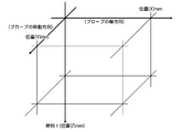
- FIG. 2 shows a detection space for the photoacoustic signal.
- the time direction of the photoacoustic signal corresponds to the depth direction (Z direction) of the photoacoustic image.
- the probe 11 has, for example, a plurality of detector elements (ultrasonic transducers) arranged one-dimensionally in the X direction. By scanning such a probe 11 in the Y direction, a photoacoustic signal can be three-dimensionally acquired. Instead of scanning a probe in which a plurality of detector elements are one-dimensionally arranged, a probe in which a plurality of detector elements are two-dimensionally arranged in the X direction and the Y direction may be used. In this case, the photoacoustic signal can be three-dimensionally acquired without scanning the probe.
- FIG. 3 shows a tomographic image (photoacoustic image) of the XZ cross section.
- the photoacoustic image generation unit when the probe 11 has a plurality of ultrasonic transducers arranged in the X direction, the photoacoustic image generation unit generates a photoacoustic image of the XZ cross section. For example, if the blood vessel traverses in the Y direction, a circular blood vessel cross section appears in the photoacoustic image of the XZ cross section.
- Three-dimensional photoacoustic image data is obtained by scanning the probe 11 in the Y direction, generating a photoacoustic image of an XZ cross section at each scanning position, and connecting a plurality of the cross sectional images.
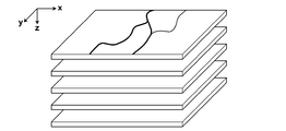
- FIG. 4 shows a cross-sectional image generated by the cross-sectional image generation means 27.
- the cross-sectional image generation unit 27 cuts out a cross section from the three-dimensional photoacoustic image data in a plane (XY plane) parallel to the acoustic wave detection surface of the probe 11 along, for example, the Z axis, To generate cross-sectional image data.
- the cross-sectional image generation unit 27 generates one cross-sectional image data by projecting the maximum value of a plurality of pieces of image data corresponding to a thickness of 2 mm in the depth direction (Z direction), for example.
- the cross-sectional image generation unit 27 cuts out cross sections at a plurality of positions arranged at equal intervals along the Z axis, for example, and generates cross-sectional image data every 2 mm.
- the cross-sectional image generated by the cross-sectional image generation unit 27 is not limited to the cross-sectional image parallel to the XY plane, and the cross-sectional image generation unit 27 may generate a cross-sectional image parallel to the XZ plane or the YZ plane.
- the Fourier transform means 28 performs Fourier transform on each of the plurality of cross-sectional image data shown in FIG. 4 to generate cross-sectional image data of a plurality of spatial frequency regions.
- the spatial frequency processing means 29 extracts predetermined spatial frequency components from each of the generated cross-sectional image data of the plurality of spatial frequency regions.
- the inverse Fourier transform unit 30 inverse Fourier transforms predetermined spatial frequency components extracted from each of the plurality of cross-sectional image data in the spatial frequency domain. By performing inverse transformation, it is possible to generate cross-sectional image data after spatial frequency processing from the plurality of cross-sectional image data shown in FIG.
- the three-dimensional photoacoustic image data after spatial frequency processing can be obtained by connecting cross-sectional image data after plural spatial frequency processing.
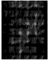
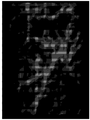
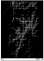
- FIG. 5 shows an example of an image of cross-sectional image data.
- the image shown in FIG. 5 corresponds to one of the plurality of cross-sectional image data shown in FIG.
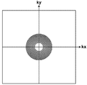
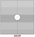
- FIG. 6 shows cross-sectional image data of a spatial frequency domain (wave number space) subjected to Fourier transform.
- the cross-sectional image data shown in FIG. 5 is converted into data in the spatial frequency domain, data shown in FIG. 6 is obtained.
- the horizontal axis represents the wave number kx
- the vertical axis represents the wave number ky.
- the intersection of kx and ky is the origin, and the spatial frequency component is lower the closer to the origin.
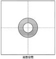
- FIG. 7 shows an example of the spatial frequency filter to which the spatial frequency processing means 29 applies.
- the white part represents a part blocked by the spatial frequency filter
- the gray part represents a part transmitted through the spatial frequency filter.
- the spatial frequency processing means 29 applies, for example, a spatial frequency filter as shown in FIG. 7 to the image data in the wave number space shown in FIG. As a result, the spatial frequency processing means 29 removes low frequency components within a certain distance from the origin in the wave number space and high frequency components longer than another constant distance from the origin in the wave number space.
- FIG. 8 shows image data of predetermined spatial frequency components which the spatial frequency processing means 29 extracts.
- the spatial frequency processing means 29 extracts the data in the annular region shown in gray in FIG. 7 in the image data in the spatial frequency region of FIG. 6 as data of a predetermined spatial frequency component. .
- FIG. 9 shows cross-sectional image data obtained by subjecting the image data of the spatial frequency component shown in FIG. 8 to inverse Fourier transform.
- the spatial frequency filter shown in FIG. 7 may be appropriately determined in accordance with the size of the object to be observed.
- the user specifies the thickness of the blood vessel to be extracted as the observation target condition.
- the spatial frequency processing means 29 sets a spatial frequency filter corresponding to the designated thickness of the blood vessel.
- the spatial frequency processing means 29 selectively transmits only the frequency band (ring band) corresponding to 1 to 2 cycles / mm on the image.
- a spatial frequency filter may be set to selectively transmit a predetermined range (for example, ⁇ ⁇ ) from the center at 2 cycles / mm. If the thickness of the blood vessel to be extracted is 1 mm, a spatial frequency filter that selectively transmits frequency components in the range of 0.3 to 0.8 cycles / mm may be used.
- the observation site may be specified.
- the spatial frequency processing means 29 information of the spatial frequency filter corresponding to the observation site is stored in advance.
- the spatial frequency processing means 29 reads out the information of the spatial frequency filter corresponding to the observation site, and sets the spatial frequency filter according to the read out information of the spatial frequency filter.
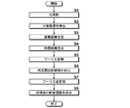
- FIG. 10 shows an operation procedure of the photoacoustic image generation apparatus 10.
- the trigger control circuit 32 outputs a flash lamp trigger signal to the laser unit 13.
- the flash lamp 41 is turned on in response to the flash lamp trigger signal, and excitation of the laser medium is started.
- the trigger control circuit 32 sends a Q switch trigger signal to the laser unit 13 and turns on the Q switch 42 to emit pulse laser light from the laser unit 13 (step S1).
- the trigger control circuit 32 outputs the Q switch trigger signal, for example, at a timing that is in a predetermined time relationship with the timing at which the flash lamp trigger signal is output.
- the trigger control circuit 32 outputs a Q switch trigger signal 150 s seconds after flash lamp emission.
- the laser beam emitted from the laser unit 13 is irradiated to the subject.
- a photoacoustic signal is generated by the irradiated pulse laser light.
- the probe 11 detects the photoacoustic signal generated in the subject (step S2).
- the photoacoustic signal detected by the probe is input to the AD conversion unit 22 through the reception circuit 21.
- the AD conversion means 22 samples the photoacoustic signal, converts it into digital data, and stores it in the reception memory 23.
- three-dimensional data of a photoacoustic signal can be obtained by scanning a probe 11 in which a plurality of ultrasonic transducers are one-dimensionally arrayed and detecting light irradiation and a photoacoustic signal at a plurality of scanning positions.
- the photoacoustic image reconstruction means 24 reads the photoacoustic signal from the reception memory 23 and reconstructs the read photoacoustic signal.
- the detection / logarithmic conversion means 25 performs detection / logarithmic conversion on the reconstructed photoacoustic signal, and the image construction means 26 generates a photoacoustic image based on the photoacoustic signal after detection / logarithmic conversion ( Step S3).
- the photoacoustic image reconstruction unit 24, the detection / logarithmic conversion unit 25, and the image construction unit 26 generate three-dimensional photoacoustic image data from three-dimensional data of the photoacoustic signal.
- the cross-sectional image generation unit 27 generates cross-sectional image data in which cross sections in a predetermined plane are integrated by a predetermined number of sheets from the photoacoustic three-dimensional image data (step S4).
- the cross-sectional image generation means 27 generates cross-sectional image data in which, for example, cross sections parallel to the acoustic wave detection surface of the probe 11 are integrated by a predetermined thickness.
- the Fourier transform means Fourier transforms the cross-sectional image generated in step S4 (step S5).
- the spatial frequency processing means 29 extracts a predetermined frequency component from the cross-sectional image data of the spatial frequency domain which has been subjected to Fourier transform (step S6).
- the inverse Fourier transform means 30 inverse Fourier transforms the data of the extracted predetermined frequency component (step S7).
- the display control means 31 displays the cross-sectional image data obtained by the inverse conversion on the display screen of the image display means 14 (step S8).
- the display control means 31 may arrange and display a plurality of cross-sectional image data after spatial frequency processing corresponding to the plurality of cross-sectional image data generated by the cross-sectional image generation means 27.
- the display control means 31 may display the cross-sectional image data (FIG. 5) before spatial frequency processing generated by the cross-sectional image generation means 27 and the cross-sectional image data (FIG. 9) after spatial frequency processing. .
- the cross-sectional image data before spatial frequency processing and the cross-sectional image data after spatial frequency processing may be displayed overlappingly with the display color changed.
- image data obtained by reconstructing a photoacoustic signal is subjected to Fourier transform, and predetermined spatial frequency components are extracted from image data in the spatial frequency domain to perform inverse Fourier transform.
- predetermined spatial frequency components are extracted from image data in the spatial frequency domain to perform inverse Fourier transform. For example, by using a spatial frequency filter as shown in FIG. 7, unnecessary low frequency components can be removed, and high frequency components (image noise) derived from tissue can be removed.
- the photoacoustic signal generated from the light absorber present inside the object is detected by each detector element with a time difference corresponding to the distance between the position of the light absorber and the detector element, It is not detected simultaneously by multiple detector elements.
- the detection signal itself is Fourier-transformed in the spatial direction, and even if a predetermined low frequency component is reduced from the detection signal in the spatial frequency domain, a blood vessel having a certain thickness can not be extracted.
- the image data after reconstruction is subjected to Fourier transform.
- a filter can be selected for blood vessel diameter information, and a desired thickness can be obtained by appropriately setting a filter to be used according to the observation target Blood vessels can be imaged.
- FIG. 7 shows an example using a filter that transmits frequency components in a certain range of distance from the origin
- spatial frequency components to be extracted are not limited to this.
- the spatial frequency that is the lower limit of the transmission band and the spatial frequency that is the upper limit may be changed according to the position in the wave number space.
- FIG. 11 shows an elliptical spatial frequency filter. If there is a region of high intensity in the wave number space, an elliptical spatial frequency filter may be used whose major axis is that region.
- the spatial frequency filter shown in FIG. 11 is used, high-frequency frequency components are extracted in the kx direction as compared to the ky direction.
- the spatial frequency filter is not limited to one that passes spatial frequency components in a predetermined band.
- FIG. 12 shows a spatial frequency filter that removes low frequency regions. When the spatial frequency filter shown in FIG. 12 is used, spatial frequency components above a certain spatial frequency can be extracted.
- the filter characteristic of the spatial frequency filter is not limited to a circle or an ellipse, and may be a polygon.
- a plurality of different wavelengths of light are emitted from the laser unit 13 to the subject, and the plurality of lights generated in the subject after the light of the plurality of wavelengths is emitted by the probe 11.
- Acoustic waves may be detected.
- the photoacoustic image generation means respectively reconstructs the photoacoustic signal detected corresponding to the light of a plurality of wavelengths, and generates a photoacoustic image.
- the Fourier transform means Fourier transforms each of the photoacoustic images corresponding to light of a plurality of wavelengths.
- the spatial frequency processing means 29 extracts predetermined spatial frequency components corresponding to each wavelength from the image data of the spatial frequency domain corresponding to the light of a plurality of wavelengths which has been subjected to Fourier transform, and the inverse Fourier transform means 30 Each of the extracted processing space frequency components is subjected to inverse Fourier transform.
- the light of the first wavelength and the light of the second wavelength are emitted from the laser unit 13 and irradiated to the subject, and the photoacoustic signal is detected when the light of each wavelength is irradiated.
- a photoacoustic image may be generated.
- the first wavelength is a wavelength corresponding to imaging of blood (blood vessels)
- the second wavelength is a wavelength corresponding to imaging of a drug (contrast agent).
- the first wavelength may be a wavelength corresponding to imaging of an artery
- the second wavelength may be a wavelength corresponding to imaging of a vein.
- the spatial frequency processing means 29 corresponds to the photoacoustic image data corresponding to the first wavelength and the second wavelength.
- Spatial frequency filters having different frequency characteristics can be used for the photoacoustic image data. That is, different spatial frequency components are extracted from the photoacoustic image data of the spatial frequency domain corresponding to the light of the first wavelength and the photoacoustic image data of the spatial frequency domain corresponding to the light of the second sound wave length. It is also good. For example, when the difference in thickness of blood vessels between arteries and veins is known in advance, different spatial frequency components are extracted from the photoacoustic image corresponding to the first wavelength and the photoacoustic image corresponding to the second wavelength. . By extracting spatial frequency components according to the object to be imaged with light of each wavelength, it is possible to extract an object to be observed from the photoacoustic image corresponding to each wavelength.
- FIG. 13 shows a photoacoustic image generation apparatus according to a second embodiment of the present invention.
- the photoacoustic image generation apparatus 10a of the present embodiment is different from the photoacoustic image generation apparatus 10 of the first embodiment shown in FIG. 1 in that the photoacoustic image generation apparatus 10a further includes a cross-sectional position selection unit 35 in the ultrasound unit 12a.
- the other points may be the same as in the first embodiment.
- the cross-sectional-position selecting unit 35 determines the cross-sectional position of the cross-sectional image data displayed on the display screen of the image display unit 14 according to the user operation.
- the display control means 31 causes the image display means 14 to display cross-sectional image data subjected to spatial frequency processing corresponding to the cross-sectional position designated by the user.
- the cross section position selection means 35 allows the user to select which position of cross section image data is to be displayed among the plurality of cross section image data shown in FIG. 4, for example.
- FIG. 14 shows an example of the display screen.
- the display control means 31 causes the image display means 14 to display, for example, a slide bar for specifying a cross-sectional position.
- Cross section position selection means determines a cross section position to be displayed according to the user's operation of the slide bar. For example, the left side of the slide bar in the plane of the drawing corresponds to the shallow position of the subject, and the right side corresponds to the deep position.
- the cross-sectional position of the cross-sectional image data after spatial frequency processing displayed on the upper portion of the slide bar changes according to the operation.
- the slide bar does not have to be provided below the cross-sectional image data, and may be provided above or to the left or right of the cross-sectional image data. Further, the slide bar does not have to be provided along with the cross-sectional image data, and may be displayed somewhere on the display screen.
- the cross-sectional-position selecting unit 35 selects the cross-sectional position of the cross-sectional image data to be displayed according to the user's operation, and the display control unit 31 determines the cross-section after spatial frequency processing of the selected cross-sectional position.
- Display image data The user can display a cross-sectional image at any cross-sectional position by operating the cross-sectional position selection unit 35.
- the user can observe the photoacoustic image in a moving image manner by, for example, using a slide bar or the like to operate so as to continuously change the cross-sectional position.
- the other effects are the same as in the first embodiment.
- FIG. 15 shows a photoacoustic image generation apparatus according to a third embodiment of the present invention.
- the photoacoustic image generation apparatus 10b of this embodiment is different from the photoacoustic image generation apparatus 10 of the first embodiment shown in FIG. 1 in that the photoacoustic image generation apparatus 10b further includes a deconvolution unit 36 in the ultrasound unit 12b.
- the other points may be the same as in the first embodiment.
- the deconvolution means 36 deconvolutes the light differential waveform which is a differential waveform of the light intensity of the light irradiated to the object from the photoacoustic signal reconstructed by the photoacoustic image reconstruction means 24. Generate The deconvolution means 36 converts the reconstructed photoacoustic signal from the signal in the time domain to the signal in the frequency domain, for example by discrete Fourier transform. Further, the light differential waveform is also converted from the signal in the time domain to the signal in the frequency domain by discrete Fourier transform. The deconvolution means 36 finds the inverse of the Fourier transformed light differential waveform as an inverse filter and applies the inverse filter to the Fourier transformed photoacoustic signal in the frequency domain.
- the light differential waveform is deconvoluted in the frequency domain signal. Thereafter, the inverse filtered photoacoustic signal is converted from the frequency domain signal to the time domain signal by inverse Fourier transform.
- the optical differential waveform may be deconvoluted from the pre-reconstruction photoacoustic signal.
- the deconvolution of the optical differential waveform will be described.
- a micro-absorbent particle which is a light absorber, and consider that this micro-absorbent particle absorbs pulse laser light to generate a pressure wave (photoacoustic pressure wave).
- the pressure waveform p micro (R, t) when a photoacoustic pressure wave generated from a micro-absorbing particle at position r is observed at position R, where t is time, is [Phys. Rev. Lett. 86 (2001) ] 3550.], it becomes the following spherical waves.
- I (t) is a time waveform of the light intensity of the excitation light
- the coefficient k is a conversion coefficient when the particle absorbs light and outputs an acoustic wave
- v s is the sound velocity of the object is there.
- Positions r and R are vectors indicating positions in space.
- the pressure generated from the micro-absorbing particles is a spherical wave proportional to the light pulse differential waveform as shown in the above equation.
- the pressure waveform obtained from the subject to be actually imaged is considered to be a waveform obtained by superimposing the above-mentioned micro absorption waveform because it has a more macroscopic absorber size (the principle of superposition).
- a (r ⁇ R) be the absorption distribution of particles that emit macro photoacoustic waves
- p macro (R, t) be an observed waveform of pressure from the macro absorber.
- the observation position R the photoacoustic wave from the absorbing particle located at the radius v s t from the observation position R is observed at each time, so the observation waveform p macro (R, t) has the following pressure It is shown by a waveform equation.
- the observed waveform shows a convolution type of light pulse differentiation.
- An absorber distribution is obtained by deconvolving the light pulse differential waveform from the observed waveform.
- the differential waveform of the light irradiated to the object is deconvoluted from the detected photoacoustic signal.
- the distribution of the light absorber can be obtained, and an absorption distribution image can be generated.
- Being able to image the distribution of the absorber makes it easier to check the position of a blood vessel or the like in the cross-sectional image after spatial frequency processing.
- the other effects are the same as in the first embodiment.
- the method of providing the photoacoustic image data to the user after spatial frequency processing is arbitrary, and is not limited to the display of the cross-sectional image as shown in FIG.
- processing is performed to extract predetermined frequency section components for three-dimensional photoacoustic image data, and a projection image is generated for three-dimensional photoacoustic image data after spatial frequency processing using maximum value projection method or the like.
- a projection image is generated for three-dimensional photoacoustic image data after spatial frequency processing using maximum value projection method or the like.
- And may be displayed on the image display means 14.
- three-dimensional display may be performed by performing volume rendering or the like on three-dimensional photoacoustic image data.
- the cross-sectional image generation unit 27 performs the two-dimensional Fourier transform of the cross-sectional image by the Fourier transform unit 28
- the three-dimensional Fourier transform may be performed on the three-dimensional photoacoustic image data by the Fourier transform unit 28 without using the cross-sectional image generation unit 27.
- a blood vessel or the like having a desired thickness can be imaged by extracting a predetermined spatial frequency region.
- the Fourier transform means 28 has been described as performing Fourier transform on the image generated by the image construction means 26.
- the signal to be Fourier transformed by the Fourier transform means 28 is at least a photoacoustic signal reconstruction means It may be reconstructed at 24 and is not limited to the image generated by the image construction means 26.
- the Fourier transform means 28 may perform Fourier transform on the output signal of the photoacoustic image reconstruction means 24. In such a case, processing after detection and logarithmic conversion may be performed on a signal obtained by the inverse Fourier transform means 30 performing inverse transform.
- the said each embodiment mainly demonstrated the example which images a blood-vessel part, it is not limited to this.
- imaging a tubular structure such as a nerve or a lymphatic vessel with a photoacoustic image
- imaging a structure of a desired size by extracting a predetermined frequency component in the spatial frequency domain it can.
- the photoacoustic image generation apparatus of this invention is not limited only to the said embodiment, A various correction and change are comprised from the structure of the said embodiment Also included in the scope of the present invention.
Landscapes
- Health & Medical Sciences (AREA)
- Life Sciences & Earth Sciences (AREA)
- Engineering & Computer Science (AREA)
- Physics & Mathematics (AREA)
- Medical Informatics (AREA)
- Biomedical Technology (AREA)
- Public Health (AREA)
- General Health & Medical Sciences (AREA)
- Pathology (AREA)
- Veterinary Medicine (AREA)
- Biophysics (AREA)
- Animal Behavior & Ethology (AREA)
- Heart & Thoracic Surgery (AREA)
- Surgery (AREA)
- Molecular Biology (AREA)
- Computer Vision & Pattern Recognition (AREA)
- Nuclear Medicine, Radiotherapy & Molecular Imaging (AREA)
- Radiology & Medical Imaging (AREA)
- Psychiatry (AREA)
- Physiology (AREA)
- Artificial Intelligence (AREA)
- Mathematical Physics (AREA)
- Signal Processing (AREA)
- Acoustics & Sound (AREA)
- Vascular Medicine (AREA)
- Data Mining & Analysis (AREA)
- Primary Health Care (AREA)
- Epidemiology (AREA)
- Databases & Information Systems (AREA)
- Ultra Sonic Daignosis Equipment (AREA)
Abstract
光音響イメージングにおいて、所望の構造物を選択的に画像化する。光音響信号を検出し、検出した光音響信号を再構成して光音響画像データを生成する。光音響画像データを2次元以上の空間でフーリエ変換し、空間周波数領域の光音響画像データを生成する。空間周波数領域の光音響画像データから所定の空間周波数成分を抽出し、抽出された空間周波数成分をフーリエ逆変換して、空間周波数処理後の光音響画像データを生成する。
Description
本発明は、光音響画像生成装置及び方法に関し、更に詳しくは、被検体に光を照射し、光照射により被検体内で生じた音響波を検出して光音響画像を生成する光音響画像生成装置及び方法に関する。
生体内部の状態を非侵襲で検査できる画像検査法の一種として、超音波検査法が知られている。超音波検査では、超音波の送信及び受信が可能な超音波探触子を用いる。超音波探触子から被検体(生体)に超音波を送信させると、その超音波は生体内部を進んでいき、組織界面で反射する。超音波探触子でその反射音波を受信し、反射超音波が超音波探触子に戻ってくるまでの時間に基づいて距離を計算することで、内部の様子を画像化することができる。
また、光音響効果を利用して生体の内部を画像化する光音響イメージングが知られている。一般に光音響イメージングでは、パルスレーザ光を生体内に照射する。生体内部では、生体組織がパルスレーザ光のエネルギーを吸収し、そのエネルギーによる断熱膨張により超音波(光音響信号)が発生する。この光音響信号を超音波プローブなどで検出し、検出信号に基づいて光音響画像を構成することで、光音響信号に基づく生体内の可視化が可能である。
ここで、光音響イメージングに関し、空間周波数処理を行うことが特許文献1に記載されている。特許文献1では、光源からの照射光を被検体に照射し、複数の検出器素子で光音響信号を検出する。検出された光音響信号は、被検体の表面で発生した光音響信号と、被検体内部で発生した光音響信号とが含まれる。特許文献1では、同一受信時間における複数の検出器素子による検出信号を空間方向にフーリエ変換し、空間周波数信号を取得する。その空間周波数信号のうち所定の周波数以下の成分を低減し、低域成分が低減された空間周波数信号に対してフーリエ逆変換を行い、逆変換により得られた信号に基づいて光音響画像を生成する。被検体の表面で発生する光音響信号は、複数の検出器素子で同時に取得されることから、被検体表面で発生する光音響波の影響を軽減したイメージングが可能となる。
また、空間周波数処理に関し、特許文献2には、超音波イメージングにおいて、イメージデータをフーリエ変換して空間周波数領域のイメージデータを生成し、フーリエ変換空間周波数領域のイメージデータの所定の低域成分を除去し、低域成分が除去された空間周波数領域のイメージデータを逆変換して実データ領域のイメージデータを生成することが記載されている。特許文献2には、低域成分はシェーディングに相当する部分であり、また、診断に必要なイメージ部分は低域に存在していないので、空間周波数の低い成分を除去することはシェーディングを除去することに相当すると記載されている。つまり、特許文献2では、イメージデータにおいて所望の見たい領域は空間周波数領域では高域に存在しているため、その必要な領域以外を除去するように空間周波数領域で低域除去を実行している。
ところで、光音響で画像化する部分として、例えば血管などが考えられる。血管には、太さの太いものから細いものまで種々のサイズの血管があり、その中から所望のサイズの血管を画像化できれば、画像診断に役立つと考えられる。しかしながら特許文献1では、光音響波の検出信号そのものに対し、同一時間の信号を空間方向にフーリエ変換しているため、所望のサイズの血管を抽出して画像化することはできない。また、特許文献2は、対象が超音波画像であると共に、単に見たい領域が空間周波数領域の高域に存在しているために、低域成分を除去する空間周波数処理を行っているだけであり、所望の構造物を抽出して画像化することはできない。
本発明は、上記に鑑み、光音響イメージングにおいて、所望の構造物を選択的に画像化並びに強調することができる光音響画像生成装置及び方法を提供することを目的とする。
上記目的を達成するために、本発明は、被検体に照射すべき光を出射する光源と、被検体に対する光照射により被検体内で生じた光音響波を検出する音響波検出手段と、光音響波の検出信号である光音響信号を再構成し画像データを生成する光音響画像生成手段と、画像データを2次元以上の空間でフーリエ変換し、空間周波数領域の画像データを生成するフーリエ変換手段と、空間周波数領域の画像データから所定の空間周波数成分を抽出する空間周波数処理手段と、抽出された空間周波数成分をフーリエ逆変換し、空間周波数処理後の画像データを生成するフーリエ逆変換手段とを備えたことを特徴とする光音響画像生成装置を提供する。
空間周波数処理手段が、第1の空間周波数以上で、かつ、第1の空間周波数よりも高い第2の周波数領域以下の空間周波数成分を抽出することとしてもよい。
上記の第1の空間周波数及び第2の空間周波数は、空間周波数領域(波数空間)における位置に応じて変化してもよい。
本発明では、空間周波数処理手段が、ユーザが指定した観察対象条件に従って、抽出する所定の空間周波数成分を決定する構成とすることができる。
3次元的に検出された光音響波に基づく3次元画像データから、3次元空間を構成する軸のうちの1つの軸に垂直な面に沿って断面を切り出し、該切り出した断面を含む1つの軸に沿った方向の所定範囲の画像データを統合した断面画像データを生成する断面画像生成手段を更に備え、フーリエ変換手段が断面画像データを2次元フーリエ変換することとしてもよい。
断面画像生成手段が、1つの軸に沿った複数の位置で断面を切り出して複数の断面画像データを生成し、フーリエ変換手段が、生成された複数の断面画像データのそれぞれをフーリエ変換して複数の空間周波数領域の画像データを生成し、空間周波数処理手段が、生成された複数の空間周波数領域の画像データのそれぞれから所定の空間周波数成分を抽出し、フーリエ逆変換手段が、複数の空間周波数領域の画像データのそれぞれから抽出された所定の空間周波数成分をフーリエ逆変換し、複数の断面画像データのそれぞれについて空間周波数処理後の断面画像データを生成するようにしてもよい。
断面画像生成手段は、断面を等間隔で切り出してもよい。
断面画像生成手段は、被検体に深さ方向に対応する軸に沿って、超音響波検出手段の音響波検出面と平行な方向に断面を切り出してもよい。
断面画像生成手段が、所定範囲内の画像データの最大値を投影し、又は所定範囲内の画像データを積分することで、所定範囲内の画像データを統合することとしてもよい。
空間周波数領域の断面画像データから抽出された所定の空間周波数成分をフーリエ逆変換することで得られた空間周波数処理後の断面画像データを表示装置に表示させる画像表示制御手段を更に備える構成としてもよい。
ユーザ操作に応じて、表示される断面画像データの断面位置を決定する断面位置選択手段を更に備え、表示制御手段が、ユーザが指定した断面位置に対応する空間周波数処理された断面画像データを表示装置に表示させてもよい。
表示制御手段が、断面位置を指定するためのスライドバーを表示装置に表示させ、断面位置選択手段が、ユーザのスライドバーの操作に応じて断面位置を決定するようにすることもできる。
表示制御手段が、空間周波数処理前の断面画像データと、空間周波数処理後の断面画像データとを並べて表示装置に表示させることとしてもよい。
表示制御手段が、空間周波数処理後の断面画像データを2値化して表示装置に表示してもよい。
フーリエ変換手段が、3次元的に検出された光音響波に基づく3次元画像データを3次元フーリエ変換するようにしてもよい。
光源が相互に異なる複数の波長の光を出射し、音響波検出手段が、複数の波長の光のそれぞれが照射された後に被検体内で発生した複数の光音響波を検出し、光音響画像生成手段が、複数の波長の光に対応して検出された光音響信号をそれぞれ再構成して画像データし、フーリエ変換手段が、複数の波長の光に対応する画像データのそれぞれをフーリエ変換し、空間周波数処理手段が、フーリエ変換された、複数の波長の光に対応する空間周波数領域の画像データから、それぞれ各波長に対応した所定の空間周波数成分を抽出し、フーリエ逆変換手段が、抽出された処理空間周波数成分のそれぞれをフーリエ逆変換してもよい。
複数の波長の光が第1の波長の光と第2の波長の光とを含み、空間周波数処理手段が、第1の波長の光に対応する空間周波数領域の画像データから抽出する空間周波数成分と、第2の波長の光に対応する空間周波数領域の画像データから抽出する空間周波数とが相互に異なるようにしてもよい。
光音響信号から、被検体に照射された光の微分波形をデコンボリューションするデコンボリューション手段を更に備える構成としてもよい。
本発明は、また、光源からの光を被検体に照射するステップと、被検体に対する光照射により被検体内で生じた光音響波を検出するステップと、光音響波の検出信号である光音響信号を再構成して画像データを生成するステップと、画像データを2次元以上の空間でフーリエ変換し、空間周波数領域の画像データを生成するステップと、空間周波数領域の画像データから所定の空間周波数成分を抽出するステップと、抽出された処理空間周波数成分をフーリエ逆変換し、空間周波数処理後の画像データを生成するステップとを有することを特徴とする光音響画像生成方法を提供する。
本発明の光音響画像生成装置及び方法は、光音響信号を再構成した画像データをフーリエ変換して空間周波数領域の画像データに変換し、その画像データから所定の空間周波数成分を抽出する。抽出した空間周波数成分をフーリエ逆変換し、空間周波数処理後の画像データを生成する。観察対象のサイズなどに応じて抽出する空間周波数成分を適宜選択することで、所望の構造物を選択的に画像化することができる。
以下、図面を参照し、本発明の実施の形態を詳細に説明する。図1は、本発明の第1実施形態の光音響画像生成装置を示す。光音響画像生成装置(光音響画像診断装置)10は、超音波探触子(プローブ)11、超音波ユニット12、及び光源(レーザユニット)13を備える。
レーザユニット13は、光源であり、被検体に照射する光(レーザ光)を生成する。レーザ光の波長は、観察対象物に応じて適宜設定すればよい。レーザユニット13は、例えばヘモグロビンの吸収が大きい波長、具体的には750nmや800nmの波長の光を出射する。レーザユニット13が出射するレーザ光は、例えば光ファイバなどの導光手段を用いてプローブ11まで導光され、プローブ11から被検体に照射される。あるいは、プローブ11以外の場所から光照射を行うこととしてもよい。
プローブ11は、被検体内からの音響波(超音波)を検出する音響波検出手段を有する。音響波検出手段の音響波検出器素子は、プローブ11は、例えば一次元的に配列された複数の超音波振動子を有している。プローブ11は、被検体内の測定対象物がレーザユニット13からの光を吸収することで生じた光音響波(以下、光音響信号とも呼ぶ)を複数の超音波振動子により検出する。
超音波ユニット12は、受信回路21、AD変換手段22、受信メモリ23、光音響画像再構成手段24、検波・対数変換手段25、画像構築手段26、断面画像生成手段27、フーリエ変換手段28、空間周波数処理手段29、フーリエ逆変換手段30、表示制御手段31、トリガ制御回路32、及び制御手段33を有する。制御手段33は、超音波ユニット12内の各部を制御する。受信回路21は、プローブ11が検出した光音響波の検出信号(光音響信号)を受信する。AD変換手段22は、受信回路21が受信した光音響信号をサンプリングしてデジタル信号に変換する。AD変換手段22は、例えばADクロック信号に同期して、所定のサンプリング周期で光音響信号をサンプリングする。
トリガ制御回路32は、レーザユニット13に対して光出射を指示する光トリガ信号を出力する。レーザユニット13は、図示しないYAGやチタン-サファイアなどのレーザ媒質を励起するフラッシュランプ41と、レーザ発振を制御するQスイッチ42とを含む。レーザユニット13は、トリガ制御回路32がフラッシュランプトリガ信号を出力すると、フラッシュランプ41を点灯し、レーザ媒質を励起する。トリガ制御回路32は、例えばフラッシュランプ41がレーザ媒質を十分に励起させると、Qスイッチトリガ信号を出力する。Qスイッチ42は、Qスイッチトリガ信号を受けるとオンし、レーザユニット13からレーザ光を出射させる。フラッシュランプ41の点灯からレーザ媒質が十分な励起状態となるまでに要する時間は、レーザ媒質の特性などから見積もることができる。
なお、トリガ制御回路32からQスイッチを制御するのに代えて、レーザユニット13内において、レーザ媒質を十分に励起させた後にQスイッチ42をオンにしてもよい。その場合は、Qスイッチ42をオンにした旨を示す信号を超音波ユニット12側に通知してもよい。ここで、光トリガ信号とは、フラッシュランプトリガ信号とQスイッチトリガ信号の少なくとも一方を含む概念である。トリガ制御回路32からQスイッチトリガ信号を出力する場合はQスイッチトリガ信号が光トリガ信号に対応し、レーザユニット13にてQスイッチトリガのタイミングを生成する場合はフラッシュランプトリガ信号が光トリガ信号に対応していてもよい。光トリガ信号が出力されることで、被検体に対するレーザ光の照射及び光音響信号の検出が行われる。
また、トリガ制御回路32は、AD変換手段22に対して、サンプリング開始を指示するサンプリングトリガ信号を出力する。トリガ制御回路32は、光トリガ信号の出力後、所定のタイミングでサンプリングトリガ信号を出力する。トリガ制御回路32は、光トリガ信号の出力後、好ましくは、被検体に実際にレーザ光が照射されるタイミングで、サンプリングトリガ信号を出力する。例えばトリガ制御回路32は、Qスイッチトリガ信号の出力と同期してサンプリングトリガ信号を出力する。AD変換手段22は、サンプリングトリガ信号を受けると、プローブ11にて検出された光音響信号のサンプリングを開始する。
AD変換手段22は、サンプリングした光音響信号を、受信メモリ23に格納する。受信メモリ23には、例えば半導体記憶装置を用いることができる。あるいは、受信メモリ23に、その他の記憶装置、例えば磁気記憶装置を用いてもよい。受信メモリ23には、光音響信号のサンプリングデータ(光音響データ)が格納される。
光音響画像再構成手段24は、受信メモリ23から光音響信号を読み出し、読み出した光音響信号を再構成する。光音響画像再構成手段24は、光音響信号に基づいて、断層画像である光音響画像の各ラインの画像データを生成する。ここで、再構成された光音響信号は、光音響画像とみなすことができる。光音響画像再構成手段24は、遅延加算法(Delay and Sum、位相整合加算、整相加算と同義)により、光音響信号を再構成する。光音響画像再構成手段24は、例えば64素子分の光音響信号を、各素子(各超音波振動子)の位置に応じた遅延時間で加算し、1ライン分のデータを生成する。その際、被検体内の音速は一定であると仮定してよいし、音速分布を考慮して各素子の遅延時間を補正してもよい。遅延加算方向に代えて、ハフ変換法又はフーリエ変換法を用いて再構成を行ってもよい。
検波・対数変換手段25は、光音響画像再構成手段24が出力する各ラインのデータの包絡線を生成し、その包絡線を対数変換してダイナミックレンジを広げる。画像構築手段26は、対数変換が施された各ラインのデータに基づいて、光音響画像を生成する。画像構築手段26は、例えば光音響信号(ピーク部分)の時間軸方向の位置を、断層画像における深さ方向の位置に変換して光音響画像を生成する。光音響画像再構成手段24、検波・対数変換手段25、及び画像構築手段26は、光音響画像生成手段に相当する。光音響画像生成手段は、例えば3次元的に検出された光音響波に基づく3次元画像データを生成する。
断面画像生成手段27は、光音響の3次元画像データから所定の面の断面を切り出す。断面画像生成手段27は、例えば3次元空間を構成する軸のうちの1つの軸に垂直な面に沿って、画像データを切り出す。断面画像生成手段27は、切り出した断面を含む、その断面に垂直な方向の所定範囲の画像データを統合した断面画像データを生成する。例えば断面画像生成手段27が、被検体の深さ方向に相当する軸のある位置で、プローブ11の音響波検出面に平行な面に沿って断面を切り出す場合、その断面位置の前後(浅い方向と深い方向)の所定枚数分の断面画像を、1つの画像に統合する。断面画像生成手段27は、例えば所定範囲内の画像データの最大値を投影することで、所定範囲内の画像データを1つの画像データに統合する。あるいは、所定範囲内の画像データを積分(平均)することで、所定範囲内の画像データを統合してもよい。
フーリエ変換手段28は、光音響の画像データをフーリエ変換し、空間周波数領域の画像データを生成する。本実施形態では、フーリエ変換手段28は、断面画像生成手段27が生成した断面画像データを、2次元フーリエ変換する。空間周波数処理手段29は、フーリエ変換された空間周波数領域の画像データから、所定の空間周波数成分を抽出する。空間周波数処理手段29は、例えば空間周波数領域の画像データから、第1の空間周波数以上で、かつ、第1の空間周波数よりも高い第2の周波数領域以下の空間周波数成分を選択的に抽出する。
フーリエ逆変換手段30は、空間周波数処理手段29で抽出された空間周波数成分をフーリエ逆変換し、空間周波数処理後の画像データを生成する。表示制御手段31は、フーリエ逆変換手段30が逆変換を行うことで得られた空間周波数処理後の断面画像データを、ディスプレイ装置などの画像表示手段14の表示画面上に表示させる。表示制御手段31は、例えば階調データで表わされている空間周波数処理後の断面画像データを、2値化して表示装置に表示させてもよい。
図2は、光音響信号の検出空間を示す。光音響信号の時間方向は、光音響画像の深さ方向(Z方向)に対応している。プローブ11は、例えばX方向に一次元配列された複数の検出器素子(超音波振動子)を有している。そのようなプローブ11をY方向に走査することにより、光音響信号を3次元的に取得できる。複数の検出器素子が一次元配列されたプローブを走査するのに代えて、複数の検出器素子がX方向及びY方向に2次元配列されたプローブを用いてもよい。この場合は、プローブを走査しなくても、光音響信号を3次元的に取得できる。
図3は、XZ断面の断層画像(光音響画像)を示す。例えばプローブ11がX方向に配列された複数の超音波振動子を有する場合、光音響画像生成手段は、XZ断面の光音響画像を生成する。例えば血管がY方向に横行しているとすると、XZ断面の光音響画像には円形の血管断面が現れる。プローブ11をY方向に走査し、各走査位置においてXZ断面の光音響画像を生成し、それら断面画像を複数枚つなげることで、3次元の光音響画像データが得られる。
図4は、断面画像生成手段27が生成する断面画像を示す。断面画像生成手段27は、例えばZ軸に沿って、プローブ11の音響波検出面と平行な面内(XY平面)で、3次元の光音響像データから断面を切り出し、所定枚数分の画像データを統合した断面画像データを生成する。断面画像生成手段27は、例えば深さ方向(Z方向)2mm分の厚みに相当する複数枚の画像データの最大値を投影することで、1つの断面画像データを生成する。断面画像生成手段27は、例えばZ軸に沿って等間隔に並ぶ複数の位置で断面を切り出し、2mmごとに断面画像データを生成する。断面画像生成手段27が生成する断面画像はXY平面に平行な断面画像には限られず、断面画像生成手段27がXZ平面又はYZ平面に平行な断面画像を生成するようにしてもよい。
フーリエ変換手段28は、図4に示す複数の断面画像データのそれぞれに対してフーリエ変換を行い、複数の空間周波数領域の断面画像データを生成する。空間周波数処理手段29は、生成された複数の空間周波数領域の断面画像データのそれぞれから所定の空間周波数成分を抽出する。フーリエ逆変換手段30は、複数の空間周波数領域の断面画像データのそれぞれから抽出された所定の空間周波数成分をフーリエ逆変換する。逆変換を行うことで、図4に示す複数の断面画像データから、空間周波数処理後の断面画像データを生成できる。複数の空間周波数処理後の断面画像データをつなげることで、空間周波数処理後の3次元光音響画像データが得られる。
図5は、断面画像データの画像例を示す。図5に示す画像は、図4に示す複数の断面画像データのうちの1つに対応する。図6は、フーリエ変換された空間周波数領域(波数空間)の断面画像データを示す。図5に示す断面画像データを空間周波数領域のデータに変換すると、図6に示すデータが得られる。図6において、横軸は波数kxを表し、縦軸は波数kyを表す。kxとkyの交点は原点であり、原点に近いほど空間周波数成分が低い。
図7は、空間周波数処理手段29が適用する空間周波数フィルタの一例を示す。図7において、白色の部分は空間周波数フィルタで遮断される部分を表し、グレーの部分は空間周波数フィルタを透過する部分を表している。空間周波数処理手段29は、例えば図7に示すような空間周波数フィルタを、図6に示す波数空間の画像データに適用する。その結果、空間周波数処理手段29は、波数空間における原点から距離が一定距離以内の低周波成分と、波数空間における原点からの距離が別の一定距離以上の高周波成分とを除去する。
図8は、空間周波数処理手段29が抽出する所定の空間周波数成分の画像データを示す。図8に示すように、空間周波数処理手段29は、図6の空間周波数領域に画像データにおける、図7にグレーで示す輪帯状の領域内のデータを、所定の空間周波数成分のデータとして抽出する。
図9は、図8に示す空間周波数成分の画像データをフーリエ逆変換することで得られた断面画像データを示す。波数空間において所定の空間周波数成分のみを選択的に抽出し、その抽出されたデータをフーリエ逆変換することで、所定の空間周波数成分に対応する部分を画像化することができる。図5に示す空間周波数処理前の断面画像データと、図9に示す断面画像データとを比較すると、画像ノイズを抑制して、血管部分をより認識しやすくなっていることが確認できる。
図7に示す空間周波数フィルタは、観察対象物の大きさなどに応じて適宜決定すればよい。例えばユーザ(オペレータ)は、観察対象条件として、抽出したい血管の太さを指定する。空間周波数処理手段29は、指定された血管の太さに対応する空間周波数フィルタを設定する。一例として、抽出対象として0.5mmの血管が指定されたとき、空間周波数処理手段29は、画像上で1~2cycle/mmに相当する周波数帯域(輪帯状)のみを選択的に透過させるような空間周波数フィルタを設定する。あるいは、2cycle/mmを中心として、そこから所定の範囲(例えば±α)の範囲を選択的に透過させるような空間周波数フィルタを設定してもよい。抽出対象の血管の太さが1mmであれば、0.3~0.8cycle/mmの範囲の周波数成分を選択的に透過させるような空間周波数フィルタを用いればよい。
上記では、ユーザが抽出したい血管の太さを指定する例を説明したが、ユーザが血管の太さを指定するのに代えて、観察部位を指定するようにしてもよい。空間周波数処理手段29には、観察部位に対応する空間周波数フィルタの情報があらかじめ記憶されている。空間周波数処理手段29は、ユーザが観察部位を指定すると、その観察部位に対応する空間周波数フィルタの情報を読み出し、読み出した空間周波数フィルタの情報に従って空間周波数フィルタを設定する。
続いて動作手順を説明する。図10は光音響画像生成装置10の動作手順を示す。トリガ制御回路32は、フラッシュランプトリガ信号をレーザユニット13に出力する。レーザユニット13では、フラッシュランプトリガ信号に応答してフラッシュランプ41が点灯し、レーザ媒質の励起が開始される。トリガ制御回路32は、Qスイッチトリガ信号をレーザユニット13に送り、Qスイッチ42をオンさせることで、レーザユニット13からパルスレーザ光を出射させる(ステップS1)。トリガ制御回路32は、例えばフラッシュランプトリガ信号を出力するタイミングと所定の時間関係にあるタイミングでQスイッチトリガ信号を出力する。例えばトリガ制御回路32は、フラッシュランプ発光から150μs秒後に、Qスイッチトリガ信号を出力する。
レーザユニット13から出射したレーザ光は、被検体に照射される。被検体内では、照射されたパルスレーザ光による光音響信号が発生する。プローブ11は、被検体内で発生した光音響信号を検出する(ステップS2)。プローブが検出した光音響信号は、受信回路21を介してAD変換手段22に入力される。AD変換手段22は、光音響信号をサンプリングしてデジタルデータに変換し、受信メモリ23に格納する。例えば複数の超音波振動子が一次元配列されたプローブ11を走査しつつ、複数の走査位置で光照射及び光音響信号の検出を行うことで、光音響信号の3次元データが得られる。
光音響画像再構成手段24は、受信メモリ23から光音響信号を読み出し、読み出した光音響信号を再構成する。検波・対数変換手段25は、再構成された光音響信号に対して検波・対数変換を行い、画像構築手段26は、検波・対数変換後の光音響信号に基づいて光音響画像を生成する(ステップS3)。光音響画像再構成手段24、検波・対数変換手段25、及び画像構築手段26は、光音響信号の3次元データから、光音響の3次元画像データを生成する。
断面画像生成手段27は、光音響の3次元画像データから、所定の枚数分だけ所定面内の断面を統合した断面画像データを生成する(ステップS4)。断面画像生成手段27は、例えばプローブ11の音響波検出面に平行な断面を、所定の厚み分ずつ統合した断面画像データを生成する。複数枚の画像を1つの断面画像データに統合することで、例えば音響波検出面に垂直な方向に血管の位置が変動する場合でも、1つの断面画像データ内に変動する血管を納めることができる。フーリエ変換手段28は、ステップS4で生成された断面画像をフーリエ変換する(ステップS5)。空間周波数処理手段29は、フーリエ変換された空間周波数領域の断面画像データから所定の周波数成分を抽出する(ステップS6)。フーリエ逆変換手段30は、抽出された所定の周波数成分のデータをフーリエ逆変換する(ステップS7)。
表示制御手段31は、画像表示手段14の表示画面上に、逆変換により得られた断面画像データを表示する(ステップS8)。表示制御手段31は、断面画像生成手段27が生成した複数の断面画像データに対応した、空間周波数処理後の複数の断面画像データを並べて表示してもよい。また、表示制御手段31は、断面画像生成手段27が生成した空間周波数処理前の断面画像データ(図5)と、空間周波数処理後の断面画像データ(図9)とを並べて表示させてもよい。並べて表示するのに代えて、空間周波数処理前の断面画像データと空間周波数処理後の断面画像データとを、表示色を変えて重ねて表示させてもよい。
本実施形態では、光音響信号を再構成した画像データをフーリエ変換し、空間周波数領域の画像データから所定の空間周波数成分を抽出してフーリエ逆変換する。例えば図7に示すような空間周波数フィルタを用いることで、不要な低周波成分を除去できると共に、組織由来の高周波成分(画像ノイズ)を除去することができる。
ここで、被検体の内部に存在する光吸収体から発生した光音響信号は、光吸収体の位置と検出器素子との間の距離に応じた時間差を持って各検出器素子で検出され、複数の検出器素子で同時には検出されない。特許文献1では、検出信号そのものを空間方向にフーリエ変換しており、空間周波数領域の検出信号から所定の低域成分を低減したとしても、ある太さの血管を抽出することはできない。これに対し、本願発明では、再構成後のイメージデータをフーリエ変換する。本実施形態では、実数法に直した波数空間でフィルタリングするので、血管径情報に対してフィルタを選定することができ、観察対象に応じて使用するフィルタを適宜設定することで、所望の太さの血管を画像化することができる。
なお、図7では原点からの距離が一定範囲の周波数成分を透過するフィルタを用いる例を示したが、抽出する空間周波数成分はこれには限定されない。透過帯域の下限となる空間周波数と、上限となる空間周波数とが、波数空間における位置に応じて変化するようにしてもよい。図11は、楕円形の空間周波数フィルタを示す。波数空間において強度の強い領域があれば、その領域を長軸方向とする楕円状の空間周波数フィルタを用いてもよい。図11に示す空間周波数フィルタを用いた場合、ky方向に比して、kx方向において高周波の周波数成分が抽出される。
また、空間周波数フィルタは、所定帯域の空間周波数成分を通過させるものには限られない。図12は、低周波領域を除去する空間周波数フィルタを示す。図12に示す空間周波数フィルタを用いた場合、ある空間周波数以上の空間周波数成分を抽出することができる。空間周波数フィルタのフィルタ特性は円形や楕円形に限られず、多角形でもよい。
本実施形態において、レーザユニット13から相互に異なる複数の波長の光を被検体に照射し、プローブ11にて、複数の波長の光のそれぞれが照射された後に被検体内で発生した複数の光音響波を検出してもよい。その場合、光音響画像生成手段は、複数の波長の光に対応して検出された光音響信号をそれぞれ再構成して光音響画像を生成する。フーリエ変換手段28は、複数の波長の光に対応する光音響画像のそれぞれをフーリエ変換する。空間周波数処理手段29は、フーリエ変換された、複数の波長の光に対応する空間周波数領域の画像データから、それぞれ各波長に対応した所定の空間周波数成分を抽出し、フーリエ逆変換手段30は、抽出された処理空間周波数成分のそれぞれをフーリエ逆変換する。
例えば、レーザユニット13から、第1の波長の光と第2の波長の光とを出射し、被検体に照射し、各波長の光が照射されたときに検出された光音響信号に基づいて光音響画像を生成してもよい。例えば、第1の波長は血液(血管)の画像化に対応した波長であり、第2の波長は薬剤(造影剤)の画像化に対応した波長であるとする。あるいは、第1の波長は動脈の画像化に対応した波長で、第2の波長は静脈の画像化に対応した波長であってもよい。
上記のように、第1の波長と第2の波長とでは画像化する対象物が異なる場合、空間周波数処理手段29は、第1の波長に対応した光音響画像データと第2の波長に対応した光音響画像データとに対し、互いに異なる周波数特性の空間周波数フィルタを用いることができる。つまり、第1の波長の光に対応する空間周波数領域の光音響画像データと、第2音波長の光に対応する空間周波数領域の光音響画像データとから、それぞれ異なる空間周波数成分を抽出してもよい。例えば動脈と静脈とで血管の太さの違いがあらかじめ分かっている場合は、第1の波長に対応する光音響画像と第2の波長に対応する光音響画像とから異なる空間周波数成分を抽出する。各波長の光で画像化する対象物に応じた空間周波数成分を抽出することで、各波長に対応した光音響画像から観察したい対象物を抽出することができる。
次いで、本発明の第2実施形態を説明する。図13は、本発明の第2実施形態の光音響画像生成装置を示す。本実施形態の光音響画像生成装置10aは、超音波ユニット12a内に断面位置選択手段35を更に有する点で、図1に示す第1実施形態の光音響画像生成装置10と相違する。その他の点は、第1実施形態と同様でよい。
断面位置選択手段35は、ユーザ操作に応じて、画像表示手段14の表示画面上に表示される断面画像データの断面位置を決定する。表示制御手段31は、ユーザが指定した断面位置に対応する空間周波数処理された断面画像データを画像表示手段14に表示させる。断面位置選択手段35は、例えば図4に示す複数の断面画像データのうちで、どの位置の断面画像データを表示対象とするのかをユーザに選択させる。
図14は、表示画面例を示す。表示制御手段31は、例えば断面位置を指定するためのスライドバーを画像表示手段14に表示させる。断面位置選択手段が、ユーザのスライドバーの操作に応じて表示する断面位置を決定する。例えばスライドバーの紙面向って左側が被検体の浅い位置に対応し、右側が深い位置に対応する。ユーザがスライドバーを操作すると、その操作に応じて、スライドバーの上部に表示される空間周波数処理後の断面画像データの断面位置が変化する。スライドバーは断面画像データの下部に設けられている必要はなく、その上部や左右に設けられていてもよい。また、スライドバーは、断面画像データに付随して設けられている必要はなく、表示画面上のどこかに表示されていればよい。
本実施形態では、断面位置選択手段35は、ユーザの操作に応じて表示されるべき断面画像データの断面位置を選択し、表示制御手段31は、選択された断面位置の空間周波数処理後の断面画像データを表示する。ユーザは、断面位置選択手段35を操作することで、任意の断面位置における断面画像を表示させることができる。また、例えばスライドバーなどを用いて断面位置を連続的に変化させるように操作することで、ユーザは、光音響画像を動画的に観察することができる。その他の効果は第1実施形態と同様である。
続いて、本発明の第3実施形態を説明する。図15は、本発明の第3実施形態の光音響画像生成装置を示す。本実施形態の光音響画像生成装置10bは、超音波ユニット12b内にデコンボリューション手段36を更に有する点で、図1に示す第1実施形態の光音響画像生成装置10と相違する。その他の点は、第1実施形態と同様でよい。
デコンボリューション手段36は、光音響画像再構成手段24で再構成された光音響信号から、被検体に照射された光の光強度の時間波形の微分波形である光微分波形をデコンボリューションした信号を生成する。デコンボリューション手段36は、例えば離散フーリエ変換により、再構成された光音響信号を時間領域の信号から周波数領域の信号へと変換する。また、光微分波形についても、離散フーリエ変換により時間領域の信号から周波数領域の信号へと変換する。デコンボリューション手段36は、フーリエ変換された光微分波形の逆数を逆フィルタとして求め、フーリエ変換された周波数領域の光音響信号に逆フィルタを適用する。逆フィルタが適用されることで、周波数領域の信号において、光微分波形がデコンボリューションされる。その後、フーリエ逆変換により、逆フィルタが適用された光音響信号を、周波数領域の信号から時間領域の信号へと変換する。再構成後の光音響信号から光微分波形をデコンボリューションするのに代えて、再構成前の光音響信号から光微分波形をデコンボリューションするようにしてもよい。
光微分波形のデコンボリューションについて説明する。光吸収体であるミクロ吸収粒子を考え、このミクロ吸収粒子がパルスレーザ光を吸収して圧力波(光音響圧力波)が生じることを考える。時刻をtとして、位置rにあるあるミクロ吸収粒子から発生する光音響圧力波を、位置Rで観測した場合の圧力波形pmicro(R,t)は、[Phys. Rev. Lett. 86(2001)3550.]より、以下の球面波となる。

ここで、I(t)は励起光の光強度の時間波形であり、係数kは、粒子が光を吸収して音響波を出力する際の変換係数であり、vsは被検体の音速である。また、位置r、Rは、空間上の位置を示すベクトルである。ミクロ吸収粒子から発生する圧力は、上記式に示すように、光パルス微分波形に比例した球面波となる。
実際にイメージングする対象から得られる圧力波形は、よりマクロな吸収体のサイズを有しているため、上記のミクロ吸収波形を重ね合わせた波形になると考える(重ね合わせの原理)。ここで、マクロな光音響波を発する粒子の吸収分布をA(r-R)とし、そのマクロな吸収体からの圧力の観測波形をpmacro(R,t)とする。観測位置Rでは、各時刻において、観測位置Rから半径vstに位置する吸収粒子からの光音響波が観測されることになるため、観測波形pmacro(R,t)は、以下の圧力波形の式で示される。

上記式(1)からわかるように、観測波形は、光パルス微分のコンボリューション型を示す。観測波形から光パルス微分波形をデコンボリューションすることで、吸収体分布が得られる。
本実施形態では、検出された光音響信号から被検体に照射された光の微分波形をデコンボリューションする。光微分波形をデコンボリューションすることで、光吸収体の分布を得ることができ、吸収分布画像を生成することができる。吸収体の分布を画像化できることで、空間周波数処理後の断面画像において、血管等の位置をより確認しやすくなる。その他の効果は第1実施形態と同様である。
なお、空間周波数処理後の光音響画像データのユーザへの提供の仕方は任意であり、図9に示すような断面画像を表示するものには限られない。例えば3次元の光音響画像データに対して所定の周波数区間成分を抽出する処理を行い、空間周波数処理後の3次元光音響画像データに対し、最大値投影法などを用いて投影画像を生成し、画像表示手段14に表示するようにしてもよい。あるいは、3次元光音響画像データに対してボリュームレンダリングなどを行って3次元表示を行ってもよい。
上記各実施形態では、断面画像生成手段27を用い、フーリエ変換手段28が断面画像に対して2次元フーリエ変換する例について説明したが、これには限定されない。断面画像生成手段27を用いずに、フーリエ変換手段28で3次元の光音響画像データに対して3次元フーリエ変換を行うようにしてもよい。この場合も、所定空間周波数領域を抽出することで、所望の太さの血管などを画像化できる。
上記各実施形態では、フーリエ変換手段28が、画像構築手段26が生成した画像に対してフーリエ変換を行うものとして説明したが、フーリエ変換手段28がフーリエ変換する信号は少なくとも光音響信号再構成手段24で再構成されていればよく、画像構築手段26が生成した画像には限定されない。フーリエ変換手段28は、光音響画像再構成手段24の出力信号に対してフーリエ変換を行ってもよい。その場合は、フーリエ逆変換手段30が逆変換することで得られた信号に対して、検波・対数変換以後の処理を行うようにすればよい。
上記各実施形態では、主に血管部分を画像化する例について説明したが、これには限定されない。例えば光音響画像で、神経やリンパ管などの管状の構造物を画像化する場合についても、空間周波数領域で所定の周波数成分を抽出することで、所望のサイズの構造物を画像化することができる。
以上、本発明をその好適な実施形態に基づいて説明したが、本発明の光音響画像生成装置は、上記実施形態にのみ限定されるものではなく、上記実施形態の構成から種々の修正及び変更を施したものも、本発明の範囲に含まれる。
Claims (19)
- 被検体に照射すべき光を出射する光源と、
被検体に対する光照射により被検体内で生じた光音響波を検出する音響波検出部と、
前記光音響波の検出信号である光音響信号を再構成し画像データを生成する光音響画像生成部と、
前記画像データを2次元以上の空間でフーリエ変換し、空間周波数領域の画像データを生成するフーリエ変換部と、
前記空間周波数領域の画像データから所定の空間周波数成分を抽出する空間周波数処理部と、
前記抽出された空間周波数成分をフーリエ逆変換し、空間周波数処理後の画像データを生成するフーリエ逆変換部とを備えたことを特徴とする光音響画像生成装置。 - 前記空間周波数処理部が、第1の空間周波数以上で、かつ、第1の空間周波数よりも高い第2の周波数領域以下の空間周波数成分を抽出することを特徴とする請求項1に記載の光音響画像生成装置。
- 前記第1の空間周波数及び第2の空間周波数が、空間周波数領域における位置に応じて変化することを特徴とする請求項2に記載の光音響画像生成装置。
- 前記空間周波数処理部が、ユーザが指定した観察対象条件に従って、前記抽出する所定の空間周波数成分を決定することを特徴とする請求項1に記載の光音響画像生成装置。
- 3次元的に検出された光音響波に基づく3次元画像データから、3次元空間を構成する軸のうちの1つの軸に垂直な面に沿って断面を切り出し、該切り出した断面を含む前記1つの軸に沿った方向の所定範囲の画像データを統合した断面画像データを生成する断面画像生成部を更に備え、
前記フーリエ変換部が前記断面画像データを2次元フーリエ変換することを特徴とする請求項1に記載の光音響画像生成装置。 - 前記断面画像生成部が、前記1つの軸に沿った複数の位置で断面を切り出して複数の断面画像データを生成し、
前記フーリエ変換部が、前記生成された複数の断面画像データのそれぞれをフーリエ変換して複数の空間周波数領域の画像データを生成し、
前記空間周波数処理部が、前記生成された複数の空間周波数領域の画像データのそれぞれから所定の空間周波数成分を抽出し、
前記フーリエ逆変換部が、複数の空間周波数領域の画像データのそれぞれから抽出された所定の空間周波数成分をフーリエ逆変換し、前記複数の断面画像データのそれぞれについて空間周波数処理後の断面画像データを生成することを特徴とする請求項5に記載の光音響画像生成装置。 - 前記断面画像生成部が、前記断面を等間隔で切り出すことを特徴とする請求項6に記載の光音響画像生成装置。
- 前記断面画像生成部が、被検体に深さ方向に対応する軸に沿って、前記超音響波検出部の音響波検出面と平行な方向に前記断面を切り出すことを特徴とする請求項5に記載の光音響画像生成装置。
- 前記断面画像生成部が、前記所定範囲内の画像データの最大値を投影し、又は前記所定範囲内の画像データを積分することで、前記所定範囲内の画像データを統合することを特徴とする請求項5に記載の光音響画像生成装置。
- 前記空間周波数領域の断面画像データから抽出された所定の空間周波数成分をフーリエ逆変換することで得られた空間周波数処理後の断面画像データを表示装置に表示させる画像表示制御部を更に備えたことを特徴とする請求項5に記載の光音響画像生成装置。
- ユーザ操作に応じて、表示される断面画像データの断面位置を決定する断面位置選択部を更に備え、前記表示制御部が、ユーザが指定した断面位置に対応する空間周波数処理された断面画像データを表示装置に表示させることを特徴とする請求項10に記載の光音響画像生成装置。
- 前記表示制御部が、前記断面位置を指定するためのスライドバーを表示装置に表示させ、前記断面位置選択部が、ユーザのスライドバーの操作に応じて前記断面位置を決定することを特徴とする請求項11に記載の光音響画像生成装置。
- 前記表示制御部が、空間周波数処理前の断面画像データと、前記空間周波数処理後の断面画像データとを並べて表示装置に表示させることを特徴とする請求項10に記載の光音響画像生成装置。
- 前記表示制御部が、前記空間周波数処理後の断面画像データを2値化して表示装置に表示させることを特徴とする請求項10に記載の光音響画像生成装置。
- 前記フーリエ変換部が、3次元的に検出された光音響波に基づく3次元画像データを3次元フーリエ変換することを特徴とする請求項1に記載の光音響画像生成装置。
- 前記光源が相互に異なる複数の波長の光を出射し、
前記音響波検出部が、前記複数の波長の光のそれぞれが照射された後に被検体内で発生した複数の光音響波を検出し、
前記光音響画像生成部が、前記複数の波長の光に対応して検出された光音響信号をそれぞれ再構成して画像データし、
フーリエ変換部が、前記複数の波長の光に対応する画像データのそれぞれをフーリエ変換し、
前記空間周波数処理部が、前記フーリエ変換された、複数の波長の光に対応する空間周波数領域の画像データから、それぞれ各波長に対応した所定の空間周波数成分を抽出し、
前記フーリエ逆変換部が、前記抽出された処理空間周波数成分のそれぞれをフーリエ逆変換することを特徴とする請求項1に記載の光音響画像生成装置。 - 前記複数の波長の光が第1の波長の光と第2の波長の光とを含み、前記空間周波数処理部が前記第1の波長の光に対応する空間周波数領域の画像データから抽出する空間周波数成分と、前記第2の波長の光に対応する空間周波数領域の画像データから抽出する空間周波数とが相互に異なることを特徴とする請求項16に記載の光音響画像生成装置。
- 前記光音響信号から、被検体に照射された光の微分波形をデコンボリューションするデコンボリューション部を更に備えたことを特徴とする請求項1に記載の光音響画像生成装置。
- 被検体に対する光照射後に、該光照射により被検体内で生じた光音響波を検出するステップと、
前記光音響波の検出信号である光音響信号を再構成して画像データを生成するステップと、
画像データを2次元以上の空間でフーリエ変換し、空間周波数領域の画像データを生成するステップと、
前記空間周波数領域の画像データから所定の空間周波数成分を抽出するステップと、
前記抽出された処理空間周波数成分をフーリエ逆変換し、空間周波数処理後の画像データを生成するステップとを有することを特徴とする光音響画像生成方法。
Priority Applications (1)
| Application Number | Priority Date | Filing Date | Title |
|---|---|---|---|
| US14/469,626 US9974440B2 (en) | 2012-02-28 | 2014-08-27 | Photoacoustic image generation device and method |
Applications Claiming Priority (2)
| Application Number | Priority Date | Filing Date | Title |
|---|---|---|---|
| JP2012040977A JP5762995B2 (ja) | 2012-02-28 | 2012-02-28 | 光音響画像生成装置及び方法 |
| JP2012-040977 | 2012-02-28 |
Related Child Applications (1)
| Application Number | Title | Priority Date | Filing Date |
|---|---|---|---|
| US14/469,626 Continuation US9974440B2 (en) | 2012-02-28 | 2014-08-27 | Photoacoustic image generation device and method |
Publications (1)
| Publication Number | Publication Date |
|---|---|
| WO2013128846A1 true WO2013128846A1 (ja) | 2013-09-06 |
Family
ID=49082062
Family Applications (1)
| Application Number | Title | Priority Date | Filing Date |
|---|---|---|---|
| PCT/JP2013/000929 WO2013128846A1 (ja) | 2012-02-28 | 2013-02-20 | 光音響画像生成装置及び方法 |
Country Status (3)
| Country | Link |
|---|---|
| US (1) | US9974440B2 (ja) |
| JP (1) | JP5762995B2 (ja) |
| WO (1) | WO2013128846A1 (ja) |
Cited By (2)
| Publication number | Priority date | Publication date | Assignee | Title |
|---|---|---|---|---|
| US20170224286A1 (en) * | 2014-09-26 | 2017-08-10 | Terumo Kabushiki Kaisha | Tomographic image forming apparatus and control method |
| JP2018057560A (ja) * | 2016-10-04 | 2018-04-12 | コニカミノルタ株式会社 | 超音波信号処理装置、超音波信号処理方法、及び、超音波診断装置 |
Families Citing this family (18)
| Publication number | Priority date | Publication date | Assignee | Title |
|---|---|---|---|---|
| JP6429444B2 (ja) * | 2013-10-02 | 2018-11-28 | キヤノン株式会社 | 画像処理装置、撮像装置及び画像処理方法 |
| US9983063B1 (en) * | 2014-04-15 | 2018-05-29 | Lockheed Martin Corporation | Multispectral imaging via coded aperture |
| JP6732476B2 (ja) * | 2015-03-04 | 2020-07-29 | キヤノン株式会社 | 被検体情報取得装置 |
| WO2016140372A1 (en) | 2015-03-04 | 2016-09-09 | Canon Kabushiki Kaisha | Object information acquiring apparatus and method for displaying image relating to object |
| US10743770B2 (en) * | 2015-05-26 | 2020-08-18 | Canon Kabushiki Kaisha | Photoacoustic device |
| WO2017014167A1 (en) * | 2015-07-21 | 2017-01-26 | Canon Kabushiki Kaisha | Object information acquiring apparatus and object information acquiring method |
| US20170112383A1 (en) * | 2015-10-23 | 2017-04-27 | Nec Laboratories America, Inc. | Three dimensional vein imaging using photo-acoustic tomography |
| JP6742734B2 (ja) * | 2016-01-21 | 2020-08-19 | キヤノン株式会社 | 被検体情報取得装置および信号処理方法 |
| US20200315574A1 (en) * | 2016-06-24 | 2020-10-08 | Canon Kabushiki Kaisha | Apparatus and information processing method |
| US10438382B2 (en) | 2017-03-27 | 2019-10-08 | Canon Kabushiki Kaisha | Image processing apparatus and image processing method |
| FR3077641B1 (fr) * | 2018-02-07 | 2020-02-21 | TiHive | Systeme d'imagerie terahertz a reflexion |
| JP7108985B2 (ja) * | 2018-08-24 | 2022-07-29 | キヤノン株式会社 | 画像処理装置、画像処理方法、プログラム |
| CN111248858B (zh) * | 2020-01-10 | 2023-07-28 | 南京景瑞康分子医药科技有限公司 | 一种基于频域波数域的光声断层成像重建方法 |
| CN111012318B (zh) * | 2020-01-18 | 2022-10-28 | 中川新迈科技有限公司 | 一种用于光声乳腺成像的面聚焦阵列探测器及系统 |
| CN111012317B (zh) * | 2020-01-18 | 2022-10-25 | 中川新迈科技有限公司 | 一种光声乳腺的图像重建方法及系统 |
| CN111012316B (zh) * | 2020-01-18 | 2022-10-28 | 中川新迈科技有限公司 | 一种光声乳腺的图像重建系统 |
| US11497436B1 (en) * | 2022-05-17 | 2022-11-15 | Ix Innovation Llc | Systems, methods, and bone mapper devices for real-time mapping and analysis of bone tissue |
| WO2023243075A1 (ja) * | 2022-06-17 | 2023-12-21 | 株式会社アドバンテスト | 光音響波測定装置、方法、プログラム、記録媒体 |
Citations (2)
| Publication number | Priority date | Publication date | Assignee | Title |
|---|---|---|---|---|
| JP2005218684A (ja) * | 2004-02-06 | 2005-08-18 | Toshiba Corp | 非侵襲生体情報映像装置及び非侵襲生体情報映像方法 |
| JP2011217767A (ja) * | 2010-04-02 | 2011-11-04 | Canon Inc | 光音響イメージング装置及び光音響イメージング方法 |
Family Cites Families (17)
| Publication number | Priority date | Publication date | Assignee | Title |
|---|---|---|---|---|
| US5136172A (en) * | 1989-08-16 | 1992-08-04 | Hitachi, Ltd. | Method and apparatus for detecting photoacoustic signal |
| JPH07282247A (ja) | 1994-04-06 | 1995-10-27 | Ge Yokogawa Medical Syst Ltd | 画像処理方法及び画像処理装置 |
| US6216025B1 (en) * | 1999-02-02 | 2001-04-10 | Optosonics, Inc. | Thermoacoustic computed tomography scanner |
| US7525661B2 (en) * | 2004-02-17 | 2009-04-28 | Andreas Mandelis | Laser photo-thermo-acoustic (PTA) frequency swept heterodyned lock-in depth profilometry imaging system |
| US20070179365A1 (en) * | 2006-01-31 | 2007-08-02 | Glucon Inc. | Method for monitoring body fluids |
| GB2444078A (en) * | 2006-11-24 | 2008-05-28 | Ucl Business Plc | Ultrasonic sensor which detects direct and reflected signals emanating from sample being imaged |
| JP5460000B2 (ja) * | 2008-08-20 | 2014-04-02 | キヤノン株式会社 | イメージング装置およびイメージング方法 |
| JP2011005042A (ja) * | 2009-06-26 | 2011-01-13 | Canon Inc | 光音響イメージング装置及び光音響イメージング方法 |
| CA2809798C (en) * | 2009-08-28 | 2018-09-18 | Visen Medical, Inc. | Systems and methods for tomographic imaging in diffuse media using a hybrid inversion technique |
| US8862206B2 (en) * | 2009-11-12 | 2014-10-14 | Virginia Tech Intellectual Properties, Inc. | Extended interior methods and systems for spectral, optical, and photoacoustic imaging |
| JP5683213B2 (ja) * | 2009-11-17 | 2015-03-11 | キヤノン株式会社 | 画像形成装置及び画像形成方法 |
| JP5451414B2 (ja) * | 2010-01-18 | 2014-03-26 | キヤノン株式会社 | 被検体情報処理装置および被検体情報処理方法 |
| WO2011091423A2 (en) * | 2010-01-25 | 2011-07-28 | The Arizona Board Of Regents On Behalf Of The University Of Arizona | Ultrasonic/photoacoustic imaging devices and methods |
| US8930145B2 (en) * | 2010-07-28 | 2015-01-06 | Covidien Lp | Light focusing continuous wave photoacoustic spectroscopy and its applications to patient monitoring |
| JP5661451B2 (ja) * | 2010-12-27 | 2015-01-28 | キヤノン株式会社 | 被検体情報取得装置及び被検体情報取得方法 |
| US8886294B2 (en) * | 2011-11-30 | 2014-11-11 | Covidien Lp | Methods and systems for photoacoustic monitoring using indicator dilution |
| US20130184544A1 (en) * | 2012-01-13 | 2013-07-18 | Nellcor Puritan Bennett Llc | Body-mounted photoacoustic sensor unit for subject monitoring |
-
2012
- 2012-02-28 JP JP2012040977A patent/JP5762995B2/ja active Active
-
2013
- 2013-02-20 WO PCT/JP2013/000929 patent/WO2013128846A1/ja active Application Filing
-
2014
- 2014-08-27 US US14/469,626 patent/US9974440B2/en active Active
Patent Citations (2)
| Publication number | Priority date | Publication date | Assignee | Title |
|---|---|---|---|---|
| JP2005218684A (ja) * | 2004-02-06 | 2005-08-18 | Toshiba Corp | 非侵襲生体情報映像装置及び非侵襲生体情報映像方法 |
| JP2011217767A (ja) * | 2010-04-02 | 2011-11-04 | Canon Inc | 光音響イメージング装置及び光音響イメージング方法 |
Cited By (3)
| Publication number | Priority date | Publication date | Assignee | Title |
|---|---|---|---|---|
| US20170224286A1 (en) * | 2014-09-26 | 2017-08-10 | Terumo Kabushiki Kaisha | Tomographic image forming apparatus and control method |
| US10898140B2 (en) * | 2014-09-26 | 2021-01-26 | Terumo Kabushiki Kaisha | Tomographic image forming apparatus and control method |
| JP2018057560A (ja) * | 2016-10-04 | 2018-04-12 | コニカミノルタ株式会社 | 超音波信号処理装置、超音波信号処理方法、及び、超音波診断装置 |
Also Published As
| Publication number | Publication date |
|---|---|
| US9974440B2 (en) | 2018-05-22 |
| JP2013176414A (ja) | 2013-09-09 |
| JP5762995B2 (ja) | 2015-08-12 |
| US20140371571A1 (en) | 2014-12-18 |
Similar Documents
| Publication | Publication Date | Title |
|---|---|---|
| WO2013128846A1 (ja) | 光音響画像生成装置及び方法 | |
| US9888856B2 (en) | Photoacoustic image generation apparatus, system and method | |
| JP5704998B2 (ja) | 光音響装置およびその制御方法 | |
| JP5743957B2 (ja) | 光音響画像生成装置及び方法 | |
| JP6411667B2 (ja) | 光音響計測装置および光音響計測装置の信号処理方法 | |
| JP5810050B2 (ja) | 音響画像生成装置および音響画像生成方法 | |
| JP5779567B2 (ja) | 光音響信号処理装置及び方法 | |
| JP6415050B2 (ja) | 被検体情報取得装置、表示方法、およびプログラム | |
| JP5777394B2 (ja) | 光音響画像化方法および装置 | |
| JP5719242B2 (ja) | ドプラ画像表示方法および装置 | |
| JP2013233386A (ja) | 光音響画像生成装置、システム、及び方法 | |
| JP2013158531A (ja) | 被検体情報取得装置及び被検体情報取得方法 | |
| JP2015142740A (ja) | 光音響装置、情報処理装置および表示方法 | |
| JP5864905B2 (ja) | 被検体情報取得装置及び被検体情報取得方法 | |
| JP5502686B2 (ja) | 光音響画像診断装置、画像生成方法、及びプログラム | |
| JP6218908B2 (ja) | 方法 | |
| WO2013076987A1 (ja) | 光音響画像生成装置および光音響画像生成方法 | |
| EP3329843B1 (en) | Display control apparatus, display control method, and program | |
| US11510630B2 (en) | Display control apparatus, image display method, and non-transitory computer-readable medium | |
| JP2012231879A (ja) | 光音響画像化方法および装置 | |
| JP6419281B2 (ja) | 情報処理装置および方法 | |
| JP2017164222A (ja) | 処理装置および処理方法 | |
| JP5946230B2 (ja) | 光音響画像化方法および装置 | |
| JP6066230B2 (ja) | 光音響画像生成装置およびその作動方法 | |
| JP2019083887A (ja) | 情報処理装置および情報処理方法 |
Legal Events
| Date | Code | Title | Description |
|---|---|---|---|
| 121 | Ep: the epo has been informed by wipo that ep was designated in this application |
Ref document number: 13754015 Country of ref document: EP Kind code of ref document: A1 |
|
| NENP | Non-entry into the national phase |
Ref country code: DE |
|
| 122 | Ep: pct application non-entry in european phase |
Ref document number: 13754015 Country of ref document: EP Kind code of ref document: A1 |