WO2013125529A1 - Noodle-steaming method and noodle-steaming device - Google Patents
Noodle-steaming method and noodle-steaming device Download PDFInfo
- Publication number
- WO2013125529A1 WO2013125529A1 PCT/JP2013/054016 JP2013054016W WO2013125529A1 WO 2013125529 A1 WO2013125529 A1 WO 2013125529A1 JP 2013054016 W JP2013054016 W JP 2013054016W WO 2013125529 A1 WO2013125529 A1 WO 2013125529A1
- Authority
- WO
- WIPO (PCT)
- Prior art keywords
- steam
- steaming
- noodle strings
- noodle
- conveyor
- Prior art date
Links
Images


Classifications
-
- A—HUMAN NECESSITIES
- A47—FURNITURE; DOMESTIC ARTICLES OR APPLIANCES; COFFEE MILLS; SPICE MILLS; SUCTION CLEANERS IN GENERAL
- A47J—KITCHEN EQUIPMENT; COFFEE MILLS; SPICE MILLS; APPARATUS FOR MAKING BEVERAGES
- A47J27/00—Cooking-vessels
- A47J27/04—Cooking-vessels for cooking food in steam; Devices for extracting fruit juice by means of steam ; Vacuum cooking vessels
-
- A—HUMAN NECESSITIES
- A23—FOODS OR FOODSTUFFS; TREATMENT THEREOF, NOT COVERED BY OTHER CLASSES
- A23L—FOODS, FOODSTUFFS, OR NON-ALCOHOLIC BEVERAGES, NOT COVERED BY SUBCLASSES A21D OR A23B-A23J; THEIR PREPARATION OR TREATMENT, e.g. COOKING, MODIFICATION OF NUTRITIVE QUALITIES, PHYSICAL TREATMENT; PRESERVATION OF FOODS OR FOODSTUFFS, IN GENERAL
- A23L3/00—Preservation of foods or foodstuffs, in general, e.g. pasteurising, sterilising, specially adapted for foods or foodstuffs
- A23L3/16—Preservation of foods or foodstuffs, in general, e.g. pasteurising, sterilising, specially adapted for foods or foodstuffs by heating loose unpacked materials
- A23L3/18—Preservation of foods or foodstuffs, in general, e.g. pasteurising, sterilising, specially adapted for foods or foodstuffs by heating loose unpacked materials while they are progressively transported through the apparatus
- A23L3/22—Preservation of foods or foodstuffs, in general, e.g. pasteurising, sterilising, specially adapted for foods or foodstuffs by heating loose unpacked materials while they are progressively transported through the apparatus with transport through tubes
-
- A—HUMAN NECESSITIES
- A23—FOODS OR FOODSTUFFS; TREATMENT THEREOF, NOT COVERED BY OTHER CLASSES
- A23L—FOODS, FOODSTUFFS, OR NON-ALCOHOLIC BEVERAGES, NOT COVERED BY SUBCLASSES A21D OR A23B-A23J; THEIR PREPARATION OR TREATMENT, e.g. COOKING, MODIFICATION OF NUTRITIVE QUALITIES, PHYSICAL TREATMENT; PRESERVATION OF FOODS OR FOODSTUFFS, IN GENERAL
- A23L5/00—Preparation or treatment of foods or foodstuffs, in general; Food or foodstuffs obtained thereby; Materials therefor
- A23L5/10—General methods of cooking foods, e.g. by roasting or frying
- A23L5/13—General methods of cooking foods, e.g. by roasting or frying using water or steam
-
- A—HUMAN NECESSITIES
- A23—FOODS OR FOODSTUFFS; TREATMENT THEREOF, NOT COVERED BY OTHER CLASSES
- A23L—FOODS, FOODSTUFFS, OR NON-ALCOHOLIC BEVERAGES, NOT COVERED BY SUBCLASSES A21D OR A23B-A23J; THEIR PREPARATION OR TREATMENT, e.g. COOKING, MODIFICATION OF NUTRITIVE QUALITIES, PHYSICAL TREATMENT; PRESERVATION OF FOODS OR FOODSTUFFS, IN GENERAL
- A23L7/00—Cereal-derived products; Malt products; Preparation or treatment thereof
- A23L7/10—Cereal-derived products
- A23L7/109—Types of pasta, e.g. macaroni or noodles
- A23L7/113—Parboiled or instant pasta
-
- A—HUMAN NECESSITIES
- A47—FURNITURE; DOMESTIC ARTICLES OR APPLIANCES; COFFEE MILLS; SPICE MILLS; SUCTION CLEANERS IN GENERAL
- A47J—KITCHEN EQUIPMENT; COFFEE MILLS; SPICE MILLS; APPARATUS FOR MAKING BEVERAGES
- A47J27/00—Cooking-vessels
- A47J2027/006—Cooking-vessels especially adapted for preparing pasta
-
- A—HUMAN NECESSITIES
- A47—FURNITURE; DOMESTIC ARTICLES OR APPLIANCES; COFFEE MILLS; SPICE MILLS; SUCTION CLEANERS IN GENERAL
- A47J—KITCHEN EQUIPMENT; COFFEE MILLS; SPICE MILLS; APPARATUS FOR MAKING BEVERAGES
- A47J27/00—Cooking-vessels
- A47J27/04—Cooking-vessels for cooking food in steam; Devices for extracting fruit juice by means of steam ; Vacuum cooking vessels
- A47J2027/043—Cooking-vessels for cooking food in steam; Devices for extracting fruit juice by means of steam ; Vacuum cooking vessels for cooking food in steam
Definitions
- the present invention relates to a noodle string steaming apparatus and a noodle string steaming method. More specifically, the present invention relates to a noodle string steaming apparatus and a noodle string steaming method particularly suitable for steaming raw noodles.
- Steamed noodles and instant noodles are produced in large quantities at high speed.
- steamed noodles and instant noodles are made by mixing raw materials such as wheat flour, buckwheat flour, starch, etc., supplying distilled water (dissolved salt, citrus, thickening polysaccharides, etc.) and mixing.
- a noodle dough called dough is prepared.
- dough a noodle dough
- it is prepared and compounded into a noodle strip by a rolling mill.
- the composite noodle strip is rolled by a plurality of rolling mills, and the noodle strip after rolling is cut out by a cutting blade roll, stacked on a conveyor, and conveyed.
- the noodle strings stacked on the conveyor are steamed by passing through a tunnel-type steaming device while being conveyed.
- Steamed noodle strings are called steamed noodles and are packaged and distributed on the market.
- the steamed noodles are subjected to a seasoning process and the like, followed by a drying process and dried with oil heat or hot air to complete an instant noodle mass.
- the amount of steam used for this purpose is also large, and a lot of energy was consumed for the generation of this steam. Therefore, if the amount of steam used can be reduced by increasing the efficiency of steaming in the main steaming process and energy can be used more efficiently, the cost of production can be reduced and the environment can be considered more. Become.
- Patent Document 1 can perform steaming efficiently, but the structure becomes complicated.
- Patent Document 2 requires accuracy because it is necessary to maintain sealing by packing.
- the present inventors aimed to develop a method for more efficient steaming in the steaming process in the production of steamed noodles and instant noodles.
- the method of steaming noodle strings is as follows. Noodles having a conveyor on which the noodle string group after cutting is placed and which conveys the noodle string group, and a tunnel-type main body provided so that the noodle string group passes along with the conveyance of the conveyor A steaming method for noodle strings using a wire steaming device, The cut noodle strings are transported on a conveyor, carried from the inlet of the main body, steamed for a predetermined time by supplying steam to the noodle strings, and then supplied with steam. A method for steaming noodle strings, including the step of steaming the noodle strings and transporting them to the outlet. " It is.
- the method of steaming noodle strings is as follows: “By transporting the noodle strings on the conveyor, After passing through a first portion that is provided on the inlet side of the main body and steams the noodle strings by supplying steam to the noodle strings, A method for steaming noodle strings, wherein the noodle strings are continuously provided on the outlet side and the first portion, and pass through a second portion that steams the noodle strings group without supplying steam. It may be.
- the internal temperature of the inner side of the inlet portion of the main body is 98 ° C. or higher, and the inner temperature of the inner side of the outlet portion is also 98 ° C. or higher.
- the temperature is preferably maintained.
- a steaming process can be performed more suitably.
- the method of steaming the noodle strings is as follows: “A steaming method for noodle strings in which the internal temperature of the inlet portion of the main body is 98 ° C. or higher and the internal temperature of the outlet portion is maintained at 98 ° C. or higher.” It may be.
- the present invention also contemplates a steaming apparatus that can realize the steaming method described above.
- the noodle string steaming device is “A noodle string group after cutting is placed on the conveyor to convey it, In a noodle string steaming device having a tunnel-type main body provided so that the noodle string group passes along with the conveyance of the conveyor, The main body is A first portion that is provided on the inlet side and steams the noodle strings by supplying steam to the noodle strings that are conveyed on the conveyor; A noodle strings steaming apparatus comprising: the first section and a second section that is provided continuously on the outlet side and steams the noodle strings group without supplying steam. ”.
- an exhaust device for sucking gas or the like may be installed to maintain the temperature of the inlet.
- the noodle string steaming device is "The noodle strings steaming device in which an inlet side exhaust device is installed on the inlet side of the main body of the noodle strings steaming device.”
- an exhaust device for sucking gas or the like may be installed in order to maintain the temperature of the outlet.
- the noodle string steaming device is "The noodle string steaming device in which an outlet side exhaust device is installed on the outlet side of the main body of the noodle string steaming device.”
- a partition member may be provided at the boundary between the steam supply unit and the steam stop unit described above to prevent vapor from evaporating in the steam supply unit.
- the noodle string steaming device is "The noodle strings steaming apparatus which provided the partition member in the boundary of the said 1st part and the said 2nd part.”
- steaming can be performed more efficiently in the steaming process in the production of steamed noodles and instant noodles.
- Raw noodle strings are made by mixing raw materials such as flour and starch in a mixer, supplying pre-prepared water, and mixing them.
- the noodle dough taken out from the mixer is called “dough”, and after ripening, it is made into two nest strips by a roll mill and combined into one nest strip by a roll mill.
- the composite band is 8 to 12 mm in thickness, and this is sequentially rolled to a predetermined band thickness by several sets of continuous roll rolling mills.
- the noodle strip after rolling is passed through between the blades of a roll-shaped rotary cutting machine, and is cut into a strip shape.
- Noodle strings include noodles having a substantially square cross section and noodles having a round cross section. Even if these noodle strings are large, one side or diameter of the cross section is approximately within 1 to 2 mm, so that they have an elongated linear shape. For this reason, it heats to the center part for a comparatively short time by the heating by the vapor
- the cut noodle strings are stacked on a conveyor and continuously conveyed on the conveyor.
- Various materials can be selected for the conveyor. Specifically, a net conveyor made of stainless steel, a rubber conveyor, a resin conveyor, or the like can be used. Generally, a net type is used.
- the tunnel-type noodle strings steaming device referred to in the present invention includes the above-described conveyor and the main body of the steaming device installed for the conveyor.
- the main body of the steaming device is arranged such that the noodle strings are carried into the main body of the steaming device as the conveyor advances.
- the main body has a box shape (may be a cylindrical shape) that extends along the transport direction and has a space formed therein.
- the main body portion includes a pair of end wall portions opposed to each other in the transport direction, an inlet portion is configured by an opening formed in one end wall portion, and an outlet portion is formed by the opening formed in the other end wall portion. Composed. Of the conveyor, at least a portion on which the noodle string group is placed extends from the entrance portion of the main body portion to the exit portion through the internal space.
- a steam pipe is generally introduced from the outside and disposed inside the main body.
- the steam pipe may be arranged at the lower part of the conveyor or at the upper part of the conveyor.
- a plurality of steam officers may be arranged in parallel with the traveling direction of the conveyor, or a plurality of steam officers may be disposed at positions that are orthogonal to the traveling direction of the conveyor.
- steaming for a certain period in the steaming of the noodle strings a process of transporting in a state where the supply of steam is stopped is performed. That is, steaming is performed by supplying steam to the noodle strings for a certain period, and then the noodle strings are steamed without supplying steam. For this reason, it is necessary to carry in steaming similarly to the case of normal steaming by bringing it into the noodle strings group from the entrance.
- steam the noodle strings without supplying steam to the noodle strings means supplying a new amount of steam by supplying a sufficient amount of steam at the stage of supplying steam and steaming.
- the steam is carried by the steam carried by the noodle strings and the steam carried along with the transport of the noodle strings.
- “The state in which the supply of steam is stopped” means that not only the above-mentioned supply is stopped by stopping the operation of the steam pipe provided at the position where the noodle string group passes, but also the position where the noodle string group passes.
- a state in which the supply of steam is stopped as a result of not providing the steam pipe and closing the hole of the steam pipe is also included. That is, the “state where the supply of steam is stopped” may be any state as long as steam is not supplied to the noodle strings group.
- supplying steam with the jetting direction of the outlet of the steam pipe toward the noodle strings group corresponds to “steam supply”. That is, after the steam pipe is ejected, the steam loses momentum and flows in a direction different from the ejection direction, and is eventually supplied to the noodle strings group at the flow destination. "Is not applicable.
- the steaming time of the noodle strings is usually about 1 minute 20 seconds (80 seconds) to 2 minutes 30 seconds (150 seconds) when a conventional steaming device is used.
- cooking for about 1/4 or more (approximately 20 seconds or more) of these cooking times, preferably about 1/3 or more (approximately 27 seconds or more) It discovered that a steaming process could be complete
- the cooking time varies depending on the amount of steam to be supplied and the thickness of the noodle strings.
- the conveyor speed is relatively fast at about 8 m / min.
- the speed of the conveyor may be approximately 1.5 m / min to 12 m / min. In general, the noodle strings are transported at the same speed.
- a method of providing a duct near the inlet of the main body (that is, the inlet side of the main body) and discharging the gas near the inlet of the main body by the duct is effective.
- the purpose of the duct in the present invention is to increase the steam density near the inlet and raise the temperature by pulling back the steam carried by the conveyor as described above.
- the decrease in steam density and temperature due to the movement of steam accompanying the progress of the conveyor is suppressed, which is different from the significance of the conventional duct.
- the temperature in the vicinity of the inlet of the main body is 98 ° C. or higher by using these ducts. More preferably, it is 99 ° C. or higher.
- the supply of steam is stopped and the noodle strings are transported to the outlet as they are.
- the supply of steam is generally supplied from a steam pipe provided at the lower or upper part of the conveyor.
- the steam pipe is provided with a plurality of holes, and the steam is supplied by ejecting steam from the holes.
- the direction and method of arrangement of the steam pipes are not particularly limited, it is general that a plurality of steam pipes are usually arranged in parallel or perpendicular to the moving direction of the conveyor.
- the steam is supplied from the inlet portion of the main body portion to the steam supply portion, that is, the front half (steam supply portion) of the main body portion, and the subsequent portion stops supplying the steam, It suffices if it reaches the inside part of the main body where the supply of steam from the section ends.
- the steam pipe does not need to be a long pipe that extends from the inlet to the outlet of the main body, and a plurality of short steam pipes are intermittently installed in the direction of the conveyor in the direction of the conveyor. May be.
- the main body part when stopping the steam supply, it is preferable to divide the main body part into a part for supplying steam and a part for transporting without supplying steam by a partition or the like. That is, at the boundary between the steam supply unit (first part that steams the noodle strings group by supplying steam to the noodle string group) and the steam stop part (second part that steams the noodle strings group without supplying steam) It is preferable to install a partition member such as a plate so as not to hinder the conveyance of the conveyor. By providing the partition member in this way, it is estimated that the degree of sealing of the steam supply unit can be increased, and the transfer of the steam to the steam stop unit can be minimized.
- the temperature does not decrease immediately.
- the steam supplied in the first half is carried along with the transport to the second half. Carried along.
- the group of noodle strings on the conveyor has a form in which elongated strings are intertwined and stacked. For this reason, unlike a normal lump, it has the form which took in many spaces as the whole noodle strings.
- the target of steaming stacked on a conveyor is a group of noodle strings, and it is considered that the characteristics in such a case influence.
- the present inventors presume that the peculiarity of the noodle strings on the conveyor during such steaming is utilized.
- steam supply part of the first half is conveyed with a conveyor, and is carried to a vapor
- the steam moves so as to accompany the movement of the noodle string group on the conveyor and the conveyor while holding the steam supplied in the steam supply section.
- the steam may volatilize without reaching the vicinity of the outlet.
- the duct on the outlet side in the present invention is to increase the steam density in the vicinity of the outlet part and to increase the temperature by attracting the steam conveyed with the conveyor to the outlet side as described above.
- the temperature in the vicinity of the outlet of the main body for example, about 10 cm from the outlet to the main body is preferably 98 ° C. or higher. More preferably, it is 99 ° C. or higher.
- the temperature of the above-mentioned entrance part and exit part shall mean the temperature of the vicinity of the noodle strings group when the cooking of the noodle strings group starts or ends. Therefore, for example, in the case of the exit portion, if the exhaust device (duct) installed at the exit portion is inserted deeply from the tunnel exit portion of the main body portion to the inside, the gas is discharged formally.
- the internal temperature near the part may be lower than 98 ° C.
- the tip portion into which the exhaust device (duct) is inserted that is, the noodle substantially.
- the temperature in the vicinity of the noodle strings at the end of the steaming of the wire shall be said.
- FIG. 1 is a schematic sectional view of a first embodiment of the noodle strings steaming apparatus of the present invention.
- the steaming apparatus of 1st embodiment has the conveyor 1 and the tunnel-type main-body part 2 in which the noodle string group M after cutting is mounted and conveyed.
- the inside of the main body is divided into a steam supply part 2-1 and a steam stop part 2-2 by a partition member 3-1, and a steam pipe 4 is provided only on the steam supply part 2-1 side.
- a first exhaust device (duct) 5-1 is disposed at the inlet of the main body 2, and a second exhaust device (duct) 5-2 is disposed at the outlet.
- the conveyor 1 is configured to pass through the main body 2.
- the noodle string group M is cut out in the previous step of this process, and is conveyed on the conveyor 1 as a plurality of noodle string groups M in a long linear state.
- the noodle string group M forms an intricate state on the conveyor and has a predetermined thickness. It should be noted that the present invention can be used regardless of whether the noodle string group M is on a so-called wave or non-wave.
- the conveyor 1 includes a conveyor belt and a sprocket, but the type is not particularly limited. Further, the conveyor belt may be of a general type, and examples thereof include a stainless steel net conveyor, a rubber or resin conveyor, and the like. Generally, a net type is used.
- the conveyor speed varies depending on production needs, but is generally 1.5 m / min to 12 m / min.
- the main body 2 is configured so that the conveyor belt of the conveyor passes through.
- the steam supply unit has a structure in which the steam pipe 4 is installed in the lower part of the conveyor and a hole is provided in the lower part of the steam pipe 4 so that steam is ejected.
- the main body 2 is divided into a steam supply unit 2-1 and a steam stop unit 2-2 from the inlet EN to the outlet of the main body 2 according to the traveling direction of the conveyor 1.
- a partition member 3-1 is provided at the boundary between the steam supply unit 2-1 and the steam stop unit 2-2 to the extent that the transport of the noodle strings M by the conveyor 1 is not hindered.
- the supply amount of the steam V varies depending on the size of the main body 2, the speed of the conveyor 1, and the external environment. For example, when the scale of the main body 2 is large, the internal temperature and steamed state can often be maintained even if the amount of steam supplied per internal volume of the main body 2 is relatively small.
- the partition member 3-1 separates the steam supply unit 2-1 and the steam stop unit 2-2, which will be described later, and the steam V supplied by the steam supply unit 2-1 is supplied to the steam stop unit 2-2. Plays a role in controlling spillage. Accordingly, the steam V in the first half steam supply section 2-1 is prevented from flowing excessively to the steam stop section 2-2 in the second half section, and is arranged so that efficient steaming can be realized.
- the partition member 3-1 is formed with a through-hole set to a size that allows the transport portion of the conveyor 1 and the noodle strings M on the transport portion to pass therethrough. The partition member 3-1 partitions between the steam supply unit 2-1 and the steam stop unit 2-2 at portions other than the through holes.
- the partition member 3-1 when the flow rate of the steam supplied in the steam supply unit 2-1, the volume of the steam supply unit 2-1, and the cross-sectional area with respect to the conveyor direction are small, it may not be necessary to provide the partition member 3-1. is there. Further, as will be described later, when the volume of the steam stop portion 2-2 or its cross-sectional area with respect to the conveyor direction is small, it may not be necessary to provide the partition member 3-1.
- the partition member 3-1 may not be provided between the steam supply unit 2-1 and the steam stop unit 2-2.
- the space constituting the steam supply unit 2-1 and the space constituting the steam stop unit 2-2 may be configured to be the same size and continuous (when the partition member 3-1 is provided, the space Although it is continuous, the space is narrowed locally at the portion of the through hole of the partition member 3-1.
- the partition member 2-2 is omitted, a region that is boiled by supplying steam to the noodle strings M, that is, a steam pipe 4 is disposed in the region of the main body 2 in the transport direction, and the steam A region where steam is supplied from the pipe 4 corresponds to the steam supply unit 2-1.
- the region is boiled without supplying steam to the noodle strings M, that is, the region where the steam pipe 4 is not disposed, or the steam tube 4 is disposed even when steam is disposed.
- the area where no steam is supplied corresponds to the steam stop section 2-2.
- the steam stop portion is configured so that the noodle strings M on the conveyor that has passed through the partition member 3-1 can pass through.
- the steam pipe 4 that is installed in the steam supply unit 2-1 is not provided.
- a dummy member 10 may be arranged in the space in the steam stop section 2-2 instead of the steam pipe 4.
- a region downstream of the outlet portion of the main body portion 2, that is, a region outside the main body portion 2, does not correspond to the steam stop portion 2-2. Since the area outside the main body 2 is a space open to the atmosphere, the steam held by the noodle strings M on the conveyor 1 and the steam remaining around the noodle strings M escape to the atmosphere. . In this portion, the noodle strings M are not steamed.
- the steam stop portion 2-2 the conveyor 1 and the noodle string group M are surrounded by the wall portion of the main body portion 2. Accordingly, the steam is likely to flow into the steam stop section 2-2. Thereby, it becomes easy for steam to stay around and inside the noodle string group M, and the noodle string group M is steamed.
- the part of the conveyor 1 that transports the noodle strings M may be covered with wall surfaces at least at the upper side, the lower side, and the side in the transport direction.
- the wall surfaces are connected without a gap (however, a slight gap may be formed as long as the effects of the present invention can be exhibited).
- the cross-sectional shape of the wall surface is not particularly limited, and may be rectangular, polygonal, or circular.
- the steam stop unit 2-1 may be partitioned on the upstream side (inlet side) in the transport direction by a wall surface (wall surface constituted by a partition member), and on the downstream side (outlet side) the wall surface (partition member or main body).
- the wall may be delimited by an outer wall on the outlet side of the part 2.
- the ratio of the volume of the steam supply unit 2-1 and the steam stop unit 2-2 is not particularly limited, but the ratio between the time for supplying and steaming the steam and the time for stopping and supplying the steam
- the steam supply part: steam stop part 1: 4 to 4: 1.
- the ratio of the volume of the steam stop unit 2-2 to the volume of the steam supply unit 2-1 may be 1/4 or more, may be 1/3 or more, may be 1/2 or more, and may be 2/3 or more. 3/4 or more.
- the volume of the steam stop unit 2-2 relative to the volume of the steam supply unit 2-1 may be 4 times or less, 3 times or less, 2 times or less, or 1.5 times or less.
- the size of the steam stop unit 2-2 in the transport direction is larger than the distance between the steam pipe 4 in the steam supply unit 2-1 and the wall surface on the inlet side of the main body unit 2, and the steam supply unit 2- It may be larger than the distance between the steam pipe 4 in 1 and the partition member 3-1. Further, the size of the steam stop unit 2-2 in the transport direction may be larger than the vertical size of the steam stop unit 2-2, and larger than the horizontal size of the steam stop unit 2-2. Good.
- the steam stop unit 2-2 does not have to be in a state where the noodle strings M are steamed without supplying steam over the entire region of the steam stop unit 2-2.
- the steam inside and around the wire M is diffused, and there is no need for substantial steaming (however, steaming is sufficient on the upstream side of the steam stop section 2-2, near the exit section) Then, the steaming necessary for the noodle strings M has been completed.
- duct (inlet side duct)
- a duct 5-1 of the first exhaust device is installed on the inlet side.
- the duct 5-1 sucks the gas near the inlet.
- the gas etc. near the inlet is sucked by the first duct 5-1.
- steam V conveyed in the advancing direction of the conveyor 1 can be returned to an inlet_port
- the steam V is moved as the conveyor 1 proceeds.
- the steaming device is divided into the first half and the second half, and in the second half, when the method of transporting while maintaining the steam atmosphere without supplying the steam, Since there is no steam supply, steam moves from the first half to the second half.
- the traveling speed of the conveyor 1 is low, the problem of a temperature drop at the entrance EN is reduced.
- the noodle strings are conveyed at a speed of about 1.5 m / min to 12 m / min because of the production speed.
- the purpose is to efficiently perform the noodle strings M to be steamed, it is necessary to perform steaming efficiently in the steam supply portion.
- a method of increasing the density and temperature of the steam near the inlet by sucking the steam V in the tunnel-type steaming apparatus through which the noodle strings on the conveyor pass is effective.
- duct (exit side duct)
- a second exhaust device (duct) 5-2 is provided at the outlet portion EX.
- the significance of the second duct 5-2 on the outlet side in the present invention is to increase the steam density near the outlet and raise the temperature by attracting the steam conveyed with the conveyor to the outlet side as described above. .
- the temperature in the vicinity of the outlet portion EX of the main body 2, for example, about 10 cm from the outlet to the main body, is preferably 98 ° C. or higher. . More preferably, it is 99 ° C. or higher.
- Steaming efficiency can be increased by raising the temperature to the vicinity of the outlet.
- the length of the main body can be minimized and space can be used effectively.
- noodle strings that have passed through the exit have been cooked and can be packaged as they are or after being added with water, oil, etc., and can be sold as they are.
- FIG. 2 explains the second embodiment of the present invention.
- the basic configuration is the same as that of the first embodiment, but in the second embodiment, the volume of the main body 2 in the steam stop unit 2-2 is smaller than that of the steam supply unit 2-1. .
- steam transported through the partitioning portion is efficiently used while suppressing vaporization of steam from the group of noodle strings transported.
- the lower partition member 3-2 is fitted under the conveyor of the steam stop section 2-2 to reduce the internal volume of the space below the lower partition member 3-2.
- the steam stop section has a cross-sectional area in the direction of travel of the conveyor that is about 40% less than the steam supply section, so that the conveyor progresses from the steam supply section 2-1 in the first half. Accordingly, it is possible to more efficiently use the steam conveyed along with the steam leaking through the partition member 3-1.
- FIG. 3 explains the third embodiment of the present invention.
- the basic configuration is the same as that of the first embodiment, but in the third embodiment, the steam stop unit 2 is changed by changing the ratio of the sizes of the steam supply unit 2-1 and the steam stop unit 2-2. The size of -2 is reduced.
- FIG. 4 when the steam stop portion 2-2 is large, only the first partition member 3-1 may be used as shown in the present embodiment. However, from the viewpoint of preventing the vapor from evaporating from the inside of the main body portion, FIG. As shown in FIG. 4, a second partition member 3-1-2 may be provided. Moreover, you may increase a partition member further.
- FIG. 7 explains the fifth embodiment of the present invention.
- the steam supply unit 2-1-1 ⁇ the steam stop unit 2-2-1 ⁇ It is continuous with the steam supply unit 2-1-2 ⁇ the steam stop unit 2-2-2.
- test examples are described in the present invention.
- the present invention is not limited to these test examples.
- a conventional tunnel-type steaming device has a uniform body 2 (total length of about 4 m, internal cross-sectional area of about 0.06 m 2 , equipped with steam pipes corresponding to each of the front and rear half portions). It was divided into two parts, and the test was conducted with the front half as the steam supply section and the latter half as the steam stop section.
- a partition portion was provided between the first half and the second half, and the ratio of the partition region opening to the internal cross-sectional area of the partition portion (the ratio of opening relative to the cross-sectional area) was about 38%.
- the speed of the conveyor passing through the steam chamber was 1.6 m / min, and the test was performed, and the time from when the noodle strings entered the main body to the exit was 2 minutes and 30 seconds.
- the noodle strings used for the test were prepared by mixing 900 g of wheat flour and 100 g of starch and adding 2.28 g of brine and 340 g of water to prepare dough. After compounding the dough, rolling was repeated a plurality of times to prepare a noodle strip having a thickness of 0.75 mm.
- the noodle strip after the treatment is cut into noodle strings by a cutting blade device (width 1.5 mm) with a square blade No. 20 and placed on a conveyor to be transported for use in a steaming process of the main body. did.
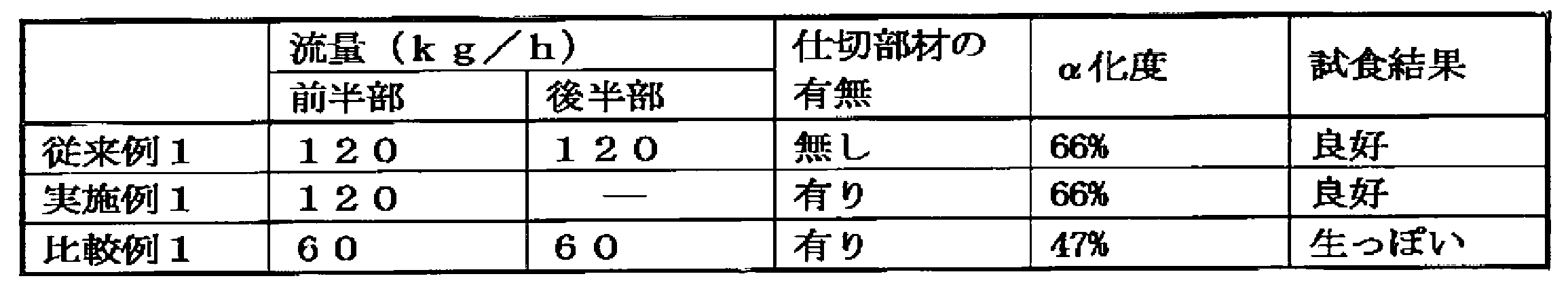
- the conventional method (conventional example 1) was not provided with a partition member as shown in FIG. 8, and steam was supplied at a flow rate of 120 kg / h in both the first half and the second half.
- Example 1 As shown in FIG. 9, a partition member is provided in the middle part, and the steam supply part for the first half part is supplied as steam at 120 kg / h as before.
- the second half steam stop stopped supplying steam.
- Comparative Example 1 a partition member is provided in the middle part as shown in FIG. 10, and 60 kg / h, which is half of the steam flow rate in the first half part of Example 1, is 120 kg / h in the first half part and the second half part. Steam was supplied.
- thermometer for the temperature measurement of the noodle strings upper space in a store
- the air volume of the duct was adjusted so that the temperature displayed for measuring the temperature in the upper space of the noodle strings was 98 ° C.
- temperature rose only to 97 degrees C or less.
- a part of the noodle strings after the steaming treatment according to the conditions of the above-mentioned conventional example 1, example 1 and comparative example 1 are sampled and the degree of alpha conversion of the noodle strings is simultaneously measured, and the noodle strings are immersed in the seasoning liquid. Then, cut into 30 cm pieces, put the noodle strings 105 g in a fly retainer, immerse the retainer in 150 ° C. fly oil (palm oil) for 2 minutes and 30 seconds, perform a frying treatment, and instant noodle chunks Was completed. The obtained instant noodle mass was put in a bowl-shaped container, and 450 g of hot water was added thereto, and the noodles were tasted after being capped for 3 minutes.
- Tasting is performed by five skilled technicians.
- the noodle strings cooked under the conventional steaming conditions (conventional example 1) were used as controls to compare the strength of steaming. The results are shown in Table 1.
- Example 1 Compared to the case where the first half and the latter half were similarly cooked as in Conventional Example 1, the degree of ⁇ -formation and the taste evaluation were the same for the case of only the first half as shown in Example 1. It was. This is a result showing that the amount of steam can be greatly reduced compared to the conventional steam flow rate.
- ⁇ Test Example 2> (When the inside of the main body is divided into three) An embodiment of the present invention was tested using a tunnel-type steaming apparatus larger than that used in Test Example 1. Incidentally, the main body portion of the tested cooking device has an overall length of about 18m, internal cross-sectional area of about 0.27 m 2, was used equipped with a steam pipe corresponding to each of the first half-middle-rear half. The inside of the main body was divided into three equal parts, and the test was conducted with only the first half or only the first half and the middle as the steam supply part, and only the second half or the second and middle as the steam stop.
- a partition member is provided between the front half and the middle portion, and between the middle portion and the rear half, and a ratio of the partition region opening to the internal cross-sectional area of the partition member (a ratio of opening relative to the cross-sectional area) is about 27%. It was.
- the speed of the conveyor passing through the steam chamber was 8 m / min, and the test was performed, and the time from when the noodle strings entered the main body to the exit was 2 minutes and 15 seconds.
- the noodle strings used for the test were prepared by mixing 900 g of wheat flour and 100 g of starch and adding 2.28 g of brine and 340 g of water to prepare dough. After compounding the dough, rolling was repeated a plurality of times to prepare a noodle strip having a thickness of 0.75 mm.
- the noodle band after the treatment was cut into noodle strings with a square blade No. 20 cutting blade device (width 1.5 mm), placed on a conveyor, and transported to be used for the steaming process of the main body. .
- the conventional method (conventional example 2) was not provided with a partition member as shown in FIG. 11, and steam was supplied at a flow rate of 400 kg / h in the first half, the middle, and the second half.
- Example 2 As shown in FIG. 12, a partition member is provided between the first half and the middle and between the middle and the second half, and the first half and the middle are used as a steam supply unit. Similarly, supply steam of 400kg / h. The second half steam stop stopped the steam supply.
- Example 3 in the state where the partition member is provided as in Example 2, the steam supply of 400 kg / h is performed only in the first half part, and the steam supply in the intermediate part and the second half part is performed. Stopped.
- the first half, the middle, and the second half have a flow rate of 133 kg / h that is one third of the steam flow of 400 kg / h in the first half of Example 3. Steam was supplied one by one.
- Example 2 and Example 3 the thermometer (for temperature measurement of the noodle strings upper space in a store
- Example 2 Compared to the case where the first half, the middle part, and the latter half were similarly cooked as in Conventional Example 2, as shown in Example 2, in the case of the first half and the middle part only, and only the first half In the case of steaming, the same degree of alpha and tasting evaluation could be obtained.
- the method of steaming the noodle strings according to form 1 “Using a noodle string steaming device having a conveyor on which a group of noodle strings after cutting is placed and transporting the noodle strings, and a tunnel-type main body provided so that the noodle strings group passes along with the transport of the conveyor A method of steaming noodle strings, Conveying the cut noodle strings on the conveyor, carrying them from the inlet of the main body, cooking for a predetermined time, and then transporting to the outlet with the steam supply stopped It may be a method of steaming noodle strings.
- the method of steaming the noodle strings according to form 2 “The steaming method of the noodle strings according to the first aspect in which the internal temperature of the inlet portion of the main body portion is 98 ° C. or higher and the internal temperature of the outlet portion is maintained at 98 ° C. or higher”.
- the steaming device for noodle strings according to aspect 3
- the main body section has a steam supply section for supplying steam from the inlet side to a group of noodle strings conveyed on a conveyor, and a steam stop section for continuously stopping the supply of steam. It may be.
- the noodle strings steaming device “In the noodle strings steaming apparatus, the noodle string steaming apparatus according to embodiment 3, wherein an exhaust device is installed near the entrance of the main body of the noodle strings steaming apparatus”.
- the noodle strings steaming device according to aspect 5 “The noodle string steaming device according to the fourth aspect, wherein an exhaust device is installed in the vicinity of the exit of the main body portion of the noodle string steaming device in the noodle string steaming device”.
- the noodle strings steaming device according to aspect 6 “The noodle strings steaming device according to any one of Embodiments 3 to 5 in which a partition member is provided at a boundary between the steam supply unit and the steam stop unit”.
Abstract
Description
「切出し後の麺線群が載置され前記麺線群を搬送するコンベアと、該コンベアの搬送に伴い前記麺線群が通過するにように設けられたトンネル型の本体部と、を有する麺線蒸煮装置を用いた麺線群の蒸煮方法であって、
切出し後の前記麺線群をコンベア上で搬送しつつ、前記本体部の入口部から搬入して、前記麺線群に蒸気を供給することによって所定時間の蒸煮を行い、その後、蒸気を供給することなく前記麺線群を蒸し、出口部まで搬送する工程を含む麺線の蒸煮方法。」、
である。 That is, the method of steaming noodle strings according to one embodiment of the present invention is as follows.
Noodles having a conveyor on which the noodle string group after cutting is placed and which conveys the noodle string group, and a tunnel-type main body provided so that the noodle string group passes along with the conveyance of the conveyor A steaming method for noodle strings using a wire steaming device,
The cut noodle strings are transported on a conveyor, carried from the inlet of the main body, steamed for a predetermined time by supplying steam to the noodle strings, and then supplied with steam. A method for steaming noodle strings, including the step of steaming the noodle strings and transporting them to the outlet. "
It is.
「前記麺線群を前記コンベア上で搬送することにより、
前記本体部の入口側に設けられ、前記麺線群に蒸気を供給することによって前記麺線群を蒸す第1の部分を通過させた後、
前記第1の部分と出口側で連続して設けられ、蒸気を供給することなく前記麺線群を蒸す第2の部分を通過させる麺線の蒸煮方法。」であってよい。 The method of steaming noodle strings according to one embodiment is as follows:
“By transporting the noodle strings on the conveyor,
After passing through a first portion that is provided on the inlet side of the main body and steams the noodle strings by supplying steam to the noodle strings,
A method for steaming noodle strings, wherein the noodle strings are continuously provided on the outlet side and the first portion, and pass through a second portion that steams the noodle strings group without supplying steam. It may be.
「 前記本体部の入口部の内部温度が98℃以上であり、かつ、出口部の内部温度が98℃以上に維持される麺線の蒸煮方法。」、
であってもよい。 That is, the method of steaming the noodle strings according to one embodiment is as follows:
“A steaming method for noodle strings in which the internal temperature of the inlet portion of the main body is 98 ° C. or higher and the internal temperature of the outlet portion is maintained at 98 ° C. or higher.”
It may be.
「 切出し後の麺線群が載置されこれを搬送するコンベアと、
該コンベアの搬送に伴い前記麺線群が通過するにように設けられたトンネル型の本体部と、を有する麺線蒸煮装置において、
前記本体部が、
入口側に設けられ、前記コンベア上で搬送される前記麺線群に蒸気を供給することによって前記麺線群を蒸す第1の部分と、
前記第1の部分と出口側で連続して設けられ、蒸気を供給することなく前記麺線群を蒸す第2の部分と、を有する麺線蒸煮装置。」、であってもよい。 That is, the noodle string steaming device according to one embodiment is
“A noodle string group after cutting is placed on the conveyor to convey it,
In a noodle string steaming device having a tunnel-type main body provided so that the noodle string group passes along with the conveyance of the conveyor,
The main body is
A first portion that is provided on the inlet side and steams the noodle strings by supplying steam to the noodle strings that are conveyed on the conveyor;
A noodle strings steaming apparatus comprising: the first section and a second section that is provided continuously on the outlet side and steams the noodle strings group without supplying steam. ”.
「 前記麺線蒸煮装置の本体部の入口側において、入口側排気装置を設置した麺線蒸煮装置。」、であってもよい。 That is, the noodle string steaming device according to one embodiment is
"The noodle strings steaming device in which an inlet side exhaust device is installed on the inlet side of the main body of the noodle strings steaming device."
「 前記麺線蒸煮装置の本体部の出口側において、出口側排気装置を設置した麺線蒸煮装置。」、であってもよい。 That is, the noodle string steaming device according to one embodiment is
"The noodle string steaming device in which an outlet side exhaust device is installed on the outlet side of the main body of the noodle string steaming device."
「 前記第1の部分と前記第2の部分との境界に仕切部材を設けた麺線蒸煮装置。」であってもよい。 That is, the noodle string steaming device according to one embodiment is
"The noodle strings steaming apparatus which provided the partition member in the boundary of the said 1st part and the said 2nd part."
<切出し後の麺線>
生麺線は、ミキサーに小麦粉、澱粉等の原材料を入れ、予め調製した練水を給水し、混ねつする。ミキサーから取り出されためん生地は、「ドウ」と呼ばれ、熟成後にロール圧延機により2枚のめん帯にされ、ロール圧延機による1枚のめん帯に複合される。 Although embodiments of the present invention are disclosed below, the present invention is not limited to these ranges.
<Noodle strings after cutting>
Raw noodle strings are made by mixing raw materials such as flour and starch in a mixer, supplying pre-prepared water, and mixing them. The noodle dough taken out from the mixer is called “dough”, and after ripening, it is made into two nest strips by a roll mill and combined into one nest strip by a roll mill.
このため、外部からの蒸気等による加熱によって、その中心部まで比較的に短時間に加熱される。また、コンベア上においては、入り組んだ複数の麺線が存在している状態となるため、蒸気を抱え込みやすく、このような麺線群がもつ形状上の特徴が本発明の実現に寄与しているものと推定される。 Noodle strings include noodles having a substantially square cross section and noodles having a round cross section. Even if these noodle strings are large, one side or diameter of the cross section is approximately within 1 to 2 mm, so that they have an elongated linear shape.
For this reason, it heats to the center part for a comparatively short time by the heating by the vapor | steam etc. from the outside. In addition, since a plurality of noodle strings are present on the conveyor, it is easy to hold steam, and the shape characteristics of such noodle strings contribute to the realization of the present invention. Estimated.
前記切出し後の麺線群がコンベア上に積層され連続的にコンベアで運ばれる。尚、本コンベアの材質は、種々のものが選択可能である。具体的には、ステンレス製のネットコンベアやゴム製や樹脂性のコンベア等が挙げられる。一般的にはネット状のタイプが用いられる。 <Conveyor>
The cut noodle strings are stacked on a conveyor and continuously conveyed on the conveyor. Various materials can be selected for the conveyor. Specifically, a net conveyor made of stainless steel, a rubber conveyor, a resin conveyor, or the like can be used. Generally, a net type is used.
本発明にいうトンネル型の麺線蒸煮装置とは、上述のようなコンベアと、このコンベアに対して設置された蒸煮装置の本体部と、を備えたものである。蒸煮装置の本体部は、コンベアの進行に伴って、麺線群が蒸煮装置の本体に搬入されるように配置されている。生麺線が蒸煮装置本体部の入口側から入ることにより、内部において蒸煮がされ、本体部の内部をコンベアが進行している間において、本体部の内部の上部又はコンベアの下部に設置された蒸気官等より噴出する蒸気によって麺線群が蒸される。なお、本体部は、搬送方向に沿って延びると共に、内部に空間が形成された箱型(筒型でもよい)の形状を有している。本体部は、搬送方向に対向する一対の端壁部を備え、一方の端壁部に形成された開口部によって入口部が構成され、他方の端壁部に形成された開口部によって出口部が構成される。コンベアのうち、少なくとも麺線群を載せる部分は、本体部の入口部から内部空間を通過して出口部まで延びている。 <Tunnel-type noodle strings steaming device>
The tunnel-type noodle strings steaming device referred to in the present invention includes the above-described conveyor and the main body of the steaming device installed for the conveyor. The main body of the steaming device is arranged such that the noodle strings are carried into the main body of the steaming device as the conveyor advances. When the raw noodle strings entered from the entrance side of the steaming device main body part, it was steamed inside, and while the conveyor was running inside the main body part, it was installed in the upper part of the main body part or the lower part of the conveyor A group of noodle strings is steamed by steam ejected from a steamer or the like. The main body has a box shape (may be a cylindrical shape) that extends along the transport direction and has a space formed therein. The main body portion includes a pair of end wall portions opposed to each other in the transport direction, an inlet portion is configured by an opening formed in one end wall portion, and an outlet portion is formed by the opening formed in the other end wall portion. Composed. Of the conveyor, at least a portion on which the noodle string group is placed extends from the entrance portion of the main body portion to the exit portion through the internal space.
本発明においては、麺線群の蒸煮において一定期間の蒸煮を行った後にその後、蒸気の供給を停止した状態で搬送する工程を経る。すなわち、一定期間の間は麺線群に蒸気を供給することによって蒸煮を行った後、蒸気の供給を行うことなく麺線群を蒸す。このため、麺線群に対して入口部から搬入して通常の蒸しの場合と同様に蒸煮を行うことが必要になる。なお、「麺線群に蒸気を供給することなく麺線群を蒸す」とは、蒸気を供給して蒸す段階において、十分な量の蒸気を供給しておくことにより、新たに蒸気を供給することなく、麺線群が抱え込んだ蒸気、及び麺線群の搬送に伴って運ばれてくる蒸気などによって蒸されることである。「蒸気の供給を停止した状態」とは、麺線群が通過する位置に設けられた蒸気管の運転を停止することによって上記の供給を停止するのみならず、麺線群が通過する位置に蒸気管を設けないこと、及び蒸気管の孔を塞ぐなどにより結果的に蒸気の供給が停止している状態も含まれる。すなわち、「蒸気の供給を停止した状態」とは、麺線群に対して蒸気の供給がなされていない状態であれば、どのような状態であってもよい。なお、蒸気管の噴出口の噴出方向を麺線群に向けて蒸気を供給することが、「蒸気の供給」に該当する。すなわち、蒸気管の噴出後に、蒸気が勢いを失って噴出方向とは異なる方向へ流れてゆき、流れた先で結果的に麺線群に供給されることは、本実施形態における「蒸気の供給」には該当しないものとする。 <Steamed for a specified period of time from the entrance>
In the present invention, after steaming for a certain period in the steaming of the noodle strings, a process of transporting in a state where the supply of steam is stopped is performed. That is, steaming is performed by supplying steam to the noodle strings for a certain period, and then the noodle strings are steamed without supplying steam. For this reason, it is necessary to carry in steaming similarly to the case of normal steaming by bringing it into the noodle strings group from the entrance. Note that “steam the noodle strings without supplying steam to the noodle strings” means supplying a new amount of steam by supplying a sufficient amount of steam at the stage of supplying steam and steaming. Without being steamed, the steam is carried by the steam carried by the noodle strings and the steam carried along with the transport of the noodle strings. “The state in which the supply of steam is stopped” means that not only the above-mentioned supply is stopped by stopping the operation of the steam pipe provided at the position where the noodle string group passes, but also the position where the noodle string group passes. A state in which the supply of steam is stopped as a result of not providing the steam pipe and closing the hole of the steam pipe is also included. That is, the “state where the supply of steam is stopped” may be any state as long as steam is not supplied to the noodle strings group. In addition, supplying steam with the jetting direction of the outlet of the steam pipe toward the noodle strings group corresponds to “steam supply”. That is, after the steam pipe is ejected, the steam loses momentum and flows in a direction different from the ejection direction, and is eventually supplied to the noodle strings group at the flow destination. "Is not applicable.
本発明おいては、上記トンネル型の蒸煮装置の入口部において蒸気を保持し、高温に維持しておくことが好ましい。すなわち、蒸煮装置の本体部における入口部から出口部までの距離は限られているため、効率的に蒸煮を行うためには、入口部から蒸気の供給が好適に行われることが好ましい。 <Inlet temperature>
In this invention, it is preferable to hold | maintain a vapor | steam in the entrance part of the said tunnel type steaming apparatus, and to maintain it at high temperature. That is, since the distance from the inlet part to the outlet part in the main body part of the steaming device is limited, it is preferable that the steam is suitably supplied from the inlet part in order to perform the steaming efficiently.
本発明では前述の蒸気の供給の後に、蒸気の供給を停止してそのまま出口部まで麺線群を搬送する。まず、蒸気の供給は一般には、コンベアの下部や上部に設けられた蒸気管より供給される。また、蒸気管には複数の孔が設けられており、当該孔から蒸気が噴出すことにより蒸気を供給する。 <Supply of steam>
In the present invention, after the supply of the steam, the supply of steam is stopped and the noodle strings are transported to the outlet as they are. First, the supply of steam is generally supplied from a steam pipe provided at the lower or upper part of the conveyor. The steam pipe is provided with a plurality of holes, and the steam is supplied by ejecting steam from the holes.
前記のように前半の蒸気供給において十分な蒸気を供給し、麺線の蒸煮を途中まで行った状態で、蒸気の供給を停止し、その後はそのままコンベア上に載置した状態で本体内を搬送させる。 <Conveyance with steam supply stopped>
Supply sufficient steam in the first half steam supply as described above, stop steam supply in the state where steaming of the noodle strings has been performed halfway, and then transport the inside of the main body while it is placed on the conveyor as it is Let
従って、例えば、出口部の場合において、出口部に設置された排気装置(ダクト)を本体部のトンネル出口部から内部まで深く挿入させて気体を排出するタイプであれば、形式的にはトンネル出口部付近の内部温度は、98℃を下回る場合もある。
しかし、実際に麺線群の蒸煮が終了しているため、これを本願発明における出口部の内部温度とはせず、前記排気装置(ダクト)の挿入された先端部、すなわち、実質的に麺線の蒸煮が終了する際の麺線群の付近の温度をいうものとする。 In addition, the temperature of the above-mentioned entrance part and exit part shall mean the temperature of the vicinity of the noodle strings group when the cooking of the noodle strings group starts or ends.
Therefore, for example, in the case of the exit portion, if the exhaust device (duct) installed at the exit portion is inserted deeply from the tunnel exit portion of the main body portion to the inside, the gas is discharged formally. The internal temperature near the part may be lower than 98 ° C.
However, since the steaming of the noodle strings is actually finished, this is not the internal temperature of the outlet portion in the present invention, but the tip portion into which the exhaust device (duct) is inserted, that is, the noodle substantially. The temperature in the vicinity of the noodle strings at the end of the steaming of the wire shall be said.
麺線群Mは本工程の前工程で切出されて、長い線状状態で複数の麺線群Mとしてコンベア1上で搬送されている。麺線群Mは、コンベア上で入り組んだ状態を形成しており、所定の厚みを有している。尚、麺線群Mの入り組みの状態はいわゆるウエーブ上であっても、非ウエーブ上であってのいずれであっても本発明を利用することができる。 <Noodle line group>
The noodle string group M is cut out in the previous step of this process, and is conveyed on the
前記工程で切出された麺線はコンベア上に積層されて搬送される。搬送コンベア1はコンベアベルトとスプロケットからなるが、タイプ等は特に限定されない。また、コンベアベルトについても一般的なタイプであればよく、ステンレス製のネットコンベアやゴム製や樹脂性のコンベア等が挙げられる。一般的にはネット状のタイプが用いられる。また、コンベアのスピードは生産のニーズによっても異なるが、概ね1.5m/分~12m/分が一般的である。 <Conveyor on which noodle strings are placed and transported>
The noodle strings cut out in the above process are stacked and conveyed on a conveyor. The
本体部2はコンベアのコンベアベルトが通過するように構成されている。また、本実施形態では、蒸気供給部において、コンベアの下部に蒸気管4が設置されていて当該蒸気管4の下部に孔が設けられており、蒸気が噴出する構造が採用されている。 <Steam supply unit>
The
仕切部材3-1は、前述の蒸気供給部2-1と後述する蒸気停止部2-2の区分けをするとともに、蒸気供給部2-1で供給される蒸気Vが蒸気停止部2-2に流出することを制御する役割を果たす。これによって、前半部の蒸気供給部2-1における蒸気Vが後半部の蒸気停止部2-2に過剰に流れるのを防ぎ、効率的な蒸煮が実現できるようにするために配置されている。仕切部材3-1には、コンベア1の搬送部分及び当該搬送部分上の麺線群Mが通過可能な大きさに設定された貫通孔が形成されている。仕切部材3-1は、貫通孔以外の部分では、蒸気供給部2-1と蒸気停止部2-2との間を仕切っている。 <Partition member>
The partition member 3-1 separates the steam supply unit 2-1 and the steam stop unit 2-2, which will be described later, and the steam V supplied by the steam supply unit 2-1 is supplied to the steam stop unit 2-2. Plays a role in controlling spillage. Accordingly, the steam V in the first half steam supply section 2-1 is prevented from flowing excessively to the steam stop section 2-2 in the second half section, and is arranged so that efficient steaming can be realized. The partition member 3-1 is formed with a through-hole set to a size that allows the transport portion of the
蒸気停止部は、仕切部材3-1を通過したコンベア上の麺線Mが通過できるように構成されている。本実施形態においては、蒸気Vの供給は行われないために蒸気供給部2-1に設置されていたような蒸気管4は設けられていない。 <Steam stop part>
The steam stop portion is configured so that the noodle strings M on the conveyor that has passed through the partition member 3-1 can pass through. In the present embodiment, since the supply of the steam V is not performed, the
本実施形態においては入口側に第一排気装置のダクト5-1が設置されている。本ダクト5-1によって入口部付近の気体を吸引する。前述したように、麺線の搬送コンベア1による搬送によって麺線Mとともに供給される蒸気Vも運ばれるために、入口部付近の蒸気密度が減少し、温度の低下が起こる場合がある。 <First exhaust system (duct) (inlet side duct)>
In the present embodiment, a duct 5-1 of the first exhaust device is installed on the inlet side. The duct 5-1 sucks the gas near the inlet. As described above, since the steam V supplied together with the noodle strings M is also transported by the transport of the noodle strings by the
本実施形態においては出口部EXに第二排気装置(ダクト)5-2が設けられている。本発明における出口側の第二ダクト5-2の意義は、上述のようにコンベアとともに搬送される蒸気を出口側まで引き付けることによって出口部付近の蒸気密度を高め、温度を高めることを目的とする。 <Second exhaust system (duct) (exit side duct)>
In the present embodiment, a second exhaust device (duct) 5-2 is provided at the outlet portion EX. The significance of the second duct 5-2 on the outlet side in the present invention is to increase the steam density near the outlet and raise the temperature by attracting the steam conveyed with the conveyor to the outlet side as described above. .
<出口を通過した麺線の処理>
本体部出口部を通過した麺線は蒸煮が完了しており、このまま又は水や油等を付加された後に包装され、そのまま蒸煮麺として販売することができる。また、蒸煮後の麺線群に対して引っ張り、着味液の浸漬等の工程を経て、カットし、当該カット後の麺線群を油熱乾燥や熱風乾燥することで即席麺とすることもできる。 Steaming efficiency can be increased by raising the temperature to the vicinity of the outlet. In addition, the length of the main body can be minimized and space can be used effectively.
<Processing of noodle strings that have passed through the exit>
The noodle strings that have passed through the main body outlet have been cooked and can be packaged as they are or after being added with water, oil, etc., and can be sold as they are. In addition, it is possible to cut instant noodle strings after steaming, immersing the seasoning liquid, etc., and making the instant noodles by oil-heat drying or hot-air drying. it can.
次に本発明の第2の実施形態について以下に説明する。図2は本発明の第2の実施形態について説明したものである。基本的な構成は第一の実施形態と同じであるが、第2の実施形態においては、蒸気停止部2-2における本体部2の容積を蒸気供給部2-1に比べて小さくしている。これによって搬送される麺線群からの蒸気の揮散を抑制しつつ、仕切り部を通じて運ばれる蒸気を効率的に利用とするものである。 <Second Embodiment>
Next, a second embodiment of the present invention will be described below. FIG. 2 explains the second embodiment of the present invention. The basic configuration is the same as that of the first embodiment, but in the second embodiment, the volume of the
次に、本発明の第3の実施形態について以下に説明する。図3は本発明の第3の実施形態について説明したものである。基本的な構成は第一の実施形態と同じであるが、第3の実施形態においては、蒸気供給部2-1と蒸気停止部2-2の大きさの割合を変えて、蒸気停止部2-2の大きさを小さくしている。 <Third Embodiment>
Next, a third embodiment of the present invention will be described below. FIG. 3 explains the third embodiment of the present invention. The basic configuration is the same as that of the first embodiment, but in the third embodiment, the
第4の実施形態においては、以下の図6に示すような蒸気供給部2-1及び蒸気停止部2-2の両方の容積を低減させた場合を示している。本実施形態においては下部仕切部材3-2と上部仕切部材3-3の両方を設けている。このように、蒸気供給部2-1及び蒸気停止部2-2の両方の容積を減少させることでより効率的な蒸煮が可能となる。 <Fourth Embodiment>
In the fourth embodiment, a case is shown in which the volumes of both the steam supply unit 2-1 and the steam stop unit 2-2 are reduced as shown in FIG. In the present embodiment, both the lower partition member 3-2 and the upper partition member 3-3 are provided. Thus, more efficient steaming is possible by reducing the volume of both the steam supply unit 2-1 and the steam stop unit 2-2.
次に本願第5の実施形態について以下に説明する。図7は本発明の第5の実施形態について説明したものである。本実施形態においては、蒸気供給部2-1-1→ 蒸気停止部2-2-1 →
蒸気供給部2-1-2 → 蒸気停止部2-2-2、と連続している。 <Fifth Embodiment>
Next, a fifth embodiment of the present application will be described below. FIG. 7 explains the fifth embodiment of the present invention. In this embodiment, the steam supply unit 2-1-1 → the steam stop unit 2-2-1 →
It is continuous with the steam supply unit 2-1-2 → the steam stop unit 2-2-2.
以下、本発明において、試験例を記載する。本発明はこれら試験例に限定されるものではない。 <Example>
Hereinafter, test examples are described in the present invention. The present invention is not limited to these test examples.
本発明の実施形態として従来までのトンネル型の蒸煮装置について本体部(全長 約4m、内部断面積 約0.06m2、前後半部のそれぞれに対応する蒸気管を装備)の内部を均等な2つの部分に区分けして、前半分を蒸気供給部、後半部を蒸気停止部として試験を行った。 <Test Example 1> (When the inside of the main body is divided into two)
As an embodiment of the present invention, a conventional tunnel-type steaming device has a uniform body 2 (total length of about 4 m, internal cross-sectional area of about 0.06 m 2 , equipped with steam pipes corresponding to each of the front and rear half portions). It was divided into two parts, and the test was conducted with the front half as the steam supply section and the latter half as the steam stop section.
本発明の実施形態として試験例1で用いたものより大型のトンネル型蒸煮装置を用いて試験した。尚、試験した蒸煮装置の本体部は、全長が約18m、内部断面積が約0.27m2であり、前半・中間・後半部のそれぞれに対応する蒸気管を装備したものを用いた。当該本体部の内部を均等な3つの部分に区分けて、前半部のみ又は、前半及び中間部を蒸気供給部、後半部のみ又は、後半及び中間部を蒸気停止部として試験を行った。 <Test Example 2> (When the inside of the main body is divided into three)
An embodiment of the present invention was tested using a tunnel-type steaming apparatus larger than that used in Test Example 1. Incidentally, the main body portion of the tested cooking device has an overall length of about 18m, internal cross-sectional area of about 0.27 m 2, was used equipped with a steam pipe corresponding to each of the first half-middle-rear half. The inside of the main body was divided into three equal parts, and the test was conducted with only the first half or only the first half and the middle as the steam supply part, and only the second half or the second and middle as the steam stop.

「切出し後の麺線群が載置されこれを搬送するコンベアと、該コンベアの搬送に伴い前記麺線群が通過するにように設けられたトンネル型の本体部を有する麺線蒸煮装置を用いた麺線群の蒸煮方法であって、
切出し後の麺線群をコンベア上で搬送しつつ、前記本体部の入口部から搬入して、所定時間の蒸煮を行い、その後、蒸気の供給を停止した状態で出口部まで搬送する工程からなる麺線の蒸煮方法」であってよい。 The method of steaming the noodle strings according to
“Using a noodle string steaming device having a conveyor on which a group of noodle strings after cutting is placed and transporting the noodle strings, and a tunnel-type main body provided so that the noodle strings group passes along with the transport of the conveyor A method of steaming noodle strings,
Conveying the cut noodle strings on the conveyor, carrying them from the inlet of the main body, cooking for a predetermined time, and then transporting to the outlet with the steam supply stopped It may be a method of steaming noodle strings.
「前記本体部の入口部の内部温度が98℃以上であり、かつ、出口部の内部温度が98℃以上を維持する形態1に記載の麺線の蒸煮方法。」であってよい。 The method of steaming the noodle strings according to
“The steaming method of the noodle strings according to the first aspect in which the internal temperature of the inlet portion of the main body portion is 98 ° C. or higher and the internal temperature of the outlet portion is maintained at 98 ° C. or higher”.
「切出し後の麺線群が載置されこれを搬送するコンベアと、該コンベアの搬送に伴い前記麺線が通過するにように設けられたトンネル型の本体部を有する麺線蒸煮装置において、
前記本体部が、入口側から、コンベア上で搬送される麺線群に蒸気を供給する蒸気供給部と、これに連続して蒸気が供給を停止する蒸気停止部を有する麺線蒸煮装置。」であってよい。 The steaming device for noodle strings according to
In the noodle strings steaming apparatus having a tunnel-type main body portion provided so that the noodle strings can be passed through the conveyor on which the noodle strings group after cutting is placed and transported,
A noodle strings steaming apparatus, wherein the main body section has a steam supply section for supplying steam from the inlet side to a group of noodle strings conveyed on a conveyor, and a steam stop section for continuously stopping the supply of steam. It may be.
「前記麺線蒸煮装置において、前記麺線蒸煮装置の本体部の入口付近において、排気装置を設置した形態3に記載の麺線蒸煮装置。」であってよい。 The noodle strings steaming device according to
“In the noodle strings steaming apparatus, the noodle string steaming apparatus according to
「前記麺線蒸煮装置において、さらに前記麺線蒸煮装置の本体部出口付近において、排気装置を設置した形態4に記載の麺線蒸煮装置。」であってよい。 The noodle strings steaming device according to
“The noodle string steaming device according to the fourth aspect, wherein an exhaust device is installed in the vicinity of the exit of the main body portion of the noodle string steaming device in the noodle string steaming device”.
「前記蒸気供給部と蒸気停止部の境界に仕切部材を設けた形態3~5のいずれかに記載の麺線蒸煮装置。」であってよい。 The noodle strings steaming device according to aspect 6
“The noodle strings steaming device according to any one of
2 本体部
2-1 蒸気供給部
2-2 蒸気停止部
3 仕切部
3-1 仕切部材
3-2 下部仕切部材
3-3 上部仕切部材
4 蒸気管
4-1 第一蒸気管
4-2 第二蒸気管
4-3 第三蒸気管
5 ダクト
5-1 第一排気装置(ダクト)(入口側)
5-2 第二排気装置(ダクト)(出口側)
本体部入口部 EN
本体部出口部 EX
麺線群 M
蒸気 V
温度計 T
1
5-2 Second exhaust system (duct) (exit side)
Main unit entrance EN
Main unit outlet EX
Noodle line group M
Steam V
Thermometer T
Claims (7)
- 切出し後の麺線群が載置され前記麺線群を搬送するコンベアと、該コンベアの搬送に伴い前記麺線群が通過するにように設けられたトンネル型の本体部と、を有する麺線蒸煮装置を用いた麺線群の蒸煮方法であって、
切出し後の前記麺線群をコンベア上で搬送しつつ、前記本体部の入口部から搬入して、前記麺線群に蒸気を供給することによって所定時間の蒸煮を行い、その後、蒸気を供給することなく前記麺線群を蒸し、出口部まで搬送する工程を含む麺線の蒸煮方法。 A noodle string having a conveyor on which the noodle string group after cutting is placed and transporting the noodle string group, and a tunnel-type main body provided so that the noodle string group passes along with the conveyance of the conveyor A steaming method for noodle strings using a steaming device,
The cut noodle strings are transported on a conveyor, carried from the inlet of the main body, steamed for a predetermined time by supplying steam to the noodle strings, and then supplied with steam. A method for steaming noodle strings, including the step of steaming the noodle strings and transporting them to the outlet. - 前記麺線群を前記コンベア上で搬送することにより、
前記本体部の入口側に設けられ、前記麺線群に蒸気を供給することによって前記麺線群を蒸す第1の部分を通過させた後、
前記第1の部分と出口側で連続して設けられ、蒸気を供給することなく前記麺線群を蒸す第2の部分を通過させる請求項1に記載の麺線の蒸煮方法。 By conveying the noodle strings on the conveyor,
After passing through a first portion that is provided on the inlet side of the main body and steams the noodle strings by supplying steam to the noodle strings,
The method for steaming noodle strings according to claim 1, wherein the noodle strings are continuously provided on the outlet side with the first portion, and the second portion that steams the noodle strings group is passed without supplying steam. - 前記本体部の入口部の内部温度が98℃以上であり、かつ、出口部の内部温度が98℃以上に維持される請求項1又は2に記載の麺線の蒸煮方法。 The method for steaming noodle strings according to claim 1 or 2, wherein the internal temperature of the inlet portion of the main body is 98 ° C or higher and the internal temperature of the outlet portion is maintained at 98 ° C or higher.
- 切出し後の麺線群が載置されこれを搬送するコンベアと、
該コンベアの搬送に伴い前記麺線群が通過するにように設けられたトンネル型の本体部と、を有する麺線蒸煮装置において、
前記本体部が、
入口側に設けられ、前記コンベア上で搬送される前記麺線群に蒸気を供給することによって前記麺線群を蒸す第1の部分と、
前記第1の部分と出口側で連続して設けられ、蒸気を供給することなく前記麺線群を蒸す第2の部分と、を有する麺線蒸煮装置。 A conveyor for carrying the noodle strings after cutting,
In a noodle string steaming device having a tunnel-type main body provided so that the noodle string group passes along with the conveyance of the conveyor,
The main body is
A first portion that is provided on the inlet side and steams the noodle strings by supplying steam to the noodle strings that are conveyed on the conveyor;
A noodle strings steaming apparatus comprising: the first section and a second section that is provided continuously on the outlet side and steams the noodle strings group without supplying steam. - 前記麺線蒸煮装置の本体部の入口側において、入口側排気装置を設置した請求項4に記載の麺線蒸煮装置。 The noodle strings steaming apparatus according to claim 4, wherein an inlet side exhaust device is installed on the inlet side of the main body of the noodle strings steaming apparatus.
- 前記麺線蒸煮装置の本体部の出口側において、出口側排気装置を設置した請求項4又は5に記載の麺線蒸煮装置。 The noodle strings steaming device according to claim 4 or 5, wherein an outlet side exhaust device is installed on the outlet side of the main body of the noodle strings steaming device.
- 前記第1の部分と前記第2の部分との境界に仕切部材を設けた請求項4~6のいずれか一項に記載の麺線蒸煮装置。 The noodle strings steaming apparatus according to any one of claims 4 to 6, wherein a partition member is provided at a boundary between the first portion and the second portion.
Priority Applications (12)
| Application Number | Priority Date | Filing Date | Title |
|---|---|---|---|
| JP2014500717A JP5559444B2 (en) | 2012-02-20 | 2013-02-19 | Noodle wire steaming method and noodle wire steaming device |
| KR1020147025789A KR101689449B1 (en) | 2012-02-20 | 2013-02-19 | Noodle-steaming method and noodle-steaming device |
| BR112014020491A BR112014020491B8 (en) | 2012-02-20 | 2013-02-19 | method of vaporizing noodles yarns and device for vaporizing noodles yarns |
| RU2014138016/13A RU2583067C2 (en) | 2012-02-20 | 2013-02-19 | Noodle steaming method and noodle steaming device |
| CN201380010285.0A CN104144614B (en) | 2012-02-20 | 2013-02-19 | Noodles steaming method and noodles steam device |
| SG11201404996RA SG11201404996RA (en) | 2012-02-20 | 2013-02-19 | Noodle-steaming method and noodle-steaming device |
| US14/379,367 US10130204B2 (en) | 2012-02-20 | 2013-02-19 | Noodle-steaming method and noodle-steaming device |
| MX2014009855A MX2014009855A (en) | 2012-02-20 | 2013-02-19 | Noodle-steaming method and noodle-steaming device. |
| IN7537DEN2014 IN2014DN07537A (en) | 2012-02-20 | 2013-02-19 | |
| EP13751312.3A EP2818054B1 (en) | 2012-02-20 | 2013-02-19 | Noodle-steaming method and noodle-steaming device |
| PH12014501882A PH12014501882A1 (en) | 2012-02-20 | 2014-08-20 | Noodle-steaming method and noodle-steaming device |
| HK15102441.4A HK1201695A1 (en) | 2012-02-20 | 2015-03-10 | Noodle-steaming method and noodle-steaming device |
Applications Claiming Priority (2)
| Application Number | Priority Date | Filing Date | Title |
|---|---|---|---|
| JP2012034134 | 2012-02-20 | ||
| JP2012-034134 | 2012-02-20 |
Publications (1)
| Publication Number | Publication Date |
|---|---|
| WO2013125529A1 true WO2013125529A1 (en) | 2013-08-29 |
Family
ID=49005714
Family Applications (1)
| Application Number | Title | Priority Date | Filing Date |
|---|---|---|---|
| PCT/JP2013/054016 WO2013125529A1 (en) | 2012-02-20 | 2013-02-19 | Noodle-steaming method and noodle-steaming device |
Country Status (16)
| Country | Link |
|---|---|
| US (1) | US10130204B2 (en) |
| EP (1) | EP2818054B1 (en) |
| JP (1) | JP5559444B2 (en) |
| KR (1) | KR101689449B1 (en) |
| CN (1) | CN104144614B (en) |
| BR (1) | BR112014020491B8 (en) |
| HK (1) | HK1201695A1 (en) |
| HU (1) | HUE045168T2 (en) |
| IN (1) | IN2014DN07537A (en) |
| MX (1) | MX2014009855A (en) |
| PH (1) | PH12014501882A1 (en) |
| RU (1) | RU2583067C2 (en) |
| SG (1) | SG11201404996RA (en) |
| TR (1) | TR201909943T4 (en) |
| TW (1) | TWI532438B (en) |
| WO (1) | WO2013125529A1 (en) |
Cited By (8)
| Publication number | Priority date | Publication date | Assignee | Title |
|---|---|---|---|---|
| JP2015186468A (en) * | 2014-03-27 | 2015-10-29 | 日清食品ホールディングス株式会社 | Multistage superheated steam processing device |
| WO2015186157A1 (en) * | 2014-06-04 | 2015-12-10 | 日清食品ホールディングス株式会社 | Multistage steam-cooking device |
| CN106455842A (en) * | 2014-06-04 | 2017-02-22 | 日清食品控股株式会社 | Multistage steam-cooking device |
| CN106659312A (en) * | 2014-07-11 | 2017-05-10 | 株式会社日冷食品 | Food heating device |
| TWI626915B (en) * | 2014-06-05 | 2018-06-21 | Nissin Foods Holdings Co Ltd | Multi-layer cooking device |
| JP2019071893A (en) * | 2019-01-08 | 2019-05-16 | 日清食品ホールディングス株式会社 | Multistage superheated steam treating apparatus |
| TWI674870B (en) * | 2014-06-05 | 2019-10-21 | 日商日清食品控股股份有限公司 | Multi-layer cooking device |
| JP2020099432A (en) * | 2018-12-20 | 2020-07-02 | 株式会社石野製作所 | Food product heating device |
Families Citing this family (8)
| Publication number | Priority date | Publication date | Assignee | Title |
|---|---|---|---|---|
| KR101733857B1 (en) * | 2015-03-16 | 2017-05-08 | 씨제이제일제당 (주) | A steaming system for food processing |
| CN104705361A (en) * | 2015-04-01 | 2015-06-17 | 河南阿凡提食品股份有限公司 | Fine dried noodle steaming system |
| CN110662464A (en) * | 2017-05-29 | 2020-01-07 | 日清食品控股株式会社 | Steaming device |
| CN111093389A (en) * | 2017-06-21 | 2020-05-01 | 皇家飞利浦有限公司 | Device and method for preparing a food puree |
| CN107897665A (en) * | 2017-11-15 | 2018-04-13 | 藤县萃香食品厂 | A kind of steamed rice cake machine |
| KR102048048B1 (en) * | 2018-01-05 | 2019-11-22 | 주식회사 싱크로티이씨 | Apparatus for steaming noodles using thermostatic device |
| IT201800006441A1 (en) | 2018-06-19 | 2019-12-19 | MACHINE FOR COOKING FOOD PRODUCTS | |
| CN213663638U (en) * | 2020-10-23 | 2021-07-13 | 颜才彪 | Full-automatic self-service steamed vermicelli roll machine |
Citations (10)
| Publication number | Priority date | Publication date | Assignee | Title |
|---|---|---|---|---|
| JPS539364A (en) * | 1976-07-13 | 1978-01-27 | Hiroyuki Yamato | Automatic boiled noodle making machine |
| JPS5372873A (en) * | 1976-12-08 | 1978-06-28 | Hiroyuki Yamato | Noodle making apparatus |
| JPS58190929U (en) * | 1982-06-16 | 1983-12-19 | 株式会社イソベ麺機 | Steamed noodle manufacturing equipment |
| JPS59103620A (en) * | 1982-12-03 | 1984-06-15 | 株式会社 ト−キョ−メンキ | Apparatus for producing steamed noodle and cooked noodle |
| JP2001299258A (en) * | 2000-04-28 | 2001-10-30 | Fuji Seisakusho:Kk | Gelatinization apparatus for noodle |
| JP2002051717A (en) | 2000-08-11 | 2002-02-19 | Fuji Seisakusho:Kk | Apparatus for gelatinizing noodle |
| JP2003159018A (en) * | 2001-11-27 | 2003-06-03 | Terauchi:Kk | Method for producing noodle |
| JP2003204766A (en) * | 2002-01-15 | 2003-07-22 | Fuji Seisakusho:Kk | Gelatinizing device for noodle |
| JP2010017167A (en) | 2008-07-08 | 2010-01-28 | Kenkichi Morishita | Multi-stage steamer for producing noodle |
| WO2011013185A1 (en) * | 2009-07-31 | 2011-02-03 | 日清食品ホールディングス株式会社 | Method for producing instant noodles |
Family Cites Families (9)
| Publication number | Priority date | Publication date | Assignee | Title |
|---|---|---|---|---|
| JPS58190929A (en) | 1982-04-30 | 1983-11-08 | Copal Co Ltd | Stop-down device of automatic iris |
| JPS62501190A (en) * | 1984-12-24 | 1987-05-14 | ビューラー アーゲー | Typical method for producing noodles, noodle products obtainable by the method, and equipment for carrying out the method |
| CN1053996A (en) * | 1991-01-15 | 1991-08-28 | 北京市食品工业研究所 | The production technology of the instant noodles |
| SG86962A1 (en) * | 1995-07-19 | 2002-03-19 | Nestle Sa | Noodle preparation process |
| JP3155488B2 (en) | 1997-04-08 | 2001-04-09 | ハウス食品株式会社 | Manufacturing method of instant noodles |
| JP2002034482A (en) * | 2000-07-28 | 2002-02-05 | Fuji Seisakusho:Kk | Apparatus for gelatinizing noodle |
| JP2002253152A (en) * | 2001-03-02 | 2002-09-10 | Sanyo Shokuhin Kk | Method for producing instant noodle |
| CN100512671C (en) * | 2003-10-22 | 2009-07-15 | 日清食品株式会社 | Noodle making method |
| KR101184638B1 (en) * | 2010-07-02 | 2012-09-20 | 염광석 | Apparatus and method of producing completely cooked instant rice in sterilized condition |
-
2013
- 2013-02-19 IN IN7537DEN2014 patent/IN2014DN07537A/en unknown
- 2013-02-19 TR TR2019/09943T patent/TR201909943T4/en unknown
- 2013-02-19 BR BR112014020491A patent/BR112014020491B8/en active IP Right Grant
- 2013-02-19 CN CN201380010285.0A patent/CN104144614B/en active Active
- 2013-02-19 WO PCT/JP2013/054016 patent/WO2013125529A1/en active Application Filing
- 2013-02-19 US US14/379,367 patent/US10130204B2/en active Active
- 2013-02-19 MX MX2014009855A patent/MX2014009855A/en unknown
- 2013-02-19 SG SG11201404996RA patent/SG11201404996RA/en unknown
- 2013-02-19 HU HUE13751312A patent/HUE045168T2/en unknown
- 2013-02-19 JP JP2014500717A patent/JP5559444B2/en active Active
- 2013-02-19 EP EP13751312.3A patent/EP2818054B1/en active Active
- 2013-02-19 KR KR1020147025789A patent/KR101689449B1/en active IP Right Grant
- 2013-02-19 RU RU2014138016/13A patent/RU2583067C2/en active
- 2013-02-20 TW TW102105862A patent/TWI532438B/en active
-
2014
- 2014-08-20 PH PH12014501882A patent/PH12014501882A1/en unknown
-
2015
- 2015-03-10 HK HK15102441.4A patent/HK1201695A1/en unknown
Patent Citations (10)
| Publication number | Priority date | Publication date | Assignee | Title |
|---|---|---|---|---|
| JPS539364A (en) * | 1976-07-13 | 1978-01-27 | Hiroyuki Yamato | Automatic boiled noodle making machine |
| JPS5372873A (en) * | 1976-12-08 | 1978-06-28 | Hiroyuki Yamato | Noodle making apparatus |
| JPS58190929U (en) * | 1982-06-16 | 1983-12-19 | 株式会社イソベ麺機 | Steamed noodle manufacturing equipment |
| JPS59103620A (en) * | 1982-12-03 | 1984-06-15 | 株式会社 ト−キョ−メンキ | Apparatus for producing steamed noodle and cooked noodle |
| JP2001299258A (en) * | 2000-04-28 | 2001-10-30 | Fuji Seisakusho:Kk | Gelatinization apparatus for noodle |
| JP2002051717A (en) | 2000-08-11 | 2002-02-19 | Fuji Seisakusho:Kk | Apparatus for gelatinizing noodle |
| JP2003159018A (en) * | 2001-11-27 | 2003-06-03 | Terauchi:Kk | Method for producing noodle |
| JP2003204766A (en) * | 2002-01-15 | 2003-07-22 | Fuji Seisakusho:Kk | Gelatinizing device for noodle |
| JP2010017167A (en) | 2008-07-08 | 2010-01-28 | Kenkichi Morishita | Multi-stage steamer for producing noodle |
| WO2011013185A1 (en) * | 2009-07-31 | 2011-02-03 | 日清食品ホールディングス株式会社 | Method for producing instant noodles |
Non-Patent Citations (1)
| Title |
|---|
| See also references of EP2818054A4 * |
Cited By (17)
| Publication number | Priority date | Publication date | Assignee | Title |
|---|---|---|---|---|
| JP2015186468A (en) * | 2014-03-27 | 2015-10-29 | 日清食品ホールディングス株式会社 | Multistage superheated steam processing device |
| RU2666827C2 (en) * | 2014-06-04 | 2018-09-12 | Ниссин Фудз Холдингз Ко., Лтд. | Multistage steam-cooking machine |
| WO2015186157A1 (en) * | 2014-06-04 | 2015-12-10 | 日清食品ホールディングス株式会社 | Multistage steam-cooking device |
| CN106413487A (en) * | 2014-06-04 | 2017-02-15 | 日清食品控股株式会社 | Multistage steam-cooking device |
| CN106455842A (en) * | 2014-06-04 | 2017-02-22 | 日清食品控股株式会社 | Multistage steam-cooking device |
| KR102201830B1 (en) * | 2014-06-04 | 2021-01-11 | 니신 쇼쿠힌 홀딩스 가부시키가이샤 | Multistage steam-cooking device |
| EP3153075A4 (en) * | 2014-06-04 | 2017-11-01 | Nissin Foods Holdings Co., Ltd. | Multistage steam-cooking device |
| KR20170015345A (en) * | 2014-06-04 | 2017-02-08 | 니신 쇼쿠힌 홀딩스 가부시키가이샤 | Multistage steam-cooking device |
| US10548426B2 (en) | 2014-06-04 | 2020-02-04 | Nissin Foods Holdings Co., Ltd. | Multistage steaming machine |
| US10524605B2 (en) | 2014-06-04 | 2020-01-07 | Nissin Foods Holdings Co., Ltd. | Multistage steaming machine |
| TWI674870B (en) * | 2014-06-05 | 2019-10-21 | 日商日清食品控股股份有限公司 | Multi-layer cooking device |
| TWI626915B (en) * | 2014-06-05 | 2018-06-21 | Nissin Foods Holdings Co Ltd | Multi-layer cooking device |
| CN106659312A (en) * | 2014-07-11 | 2017-05-10 | 株式会社日冷食品 | Food heating device |
| CN106659312B (en) * | 2014-07-11 | 2019-02-01 | 株式会社日冷食品 | Foods heat unit |
| JP2020099432A (en) * | 2018-12-20 | 2020-07-02 | 株式会社石野製作所 | Food product heating device |
| JP7411973B2 (en) | 2018-12-20 | 2024-01-12 | 株式会社石野製作所 | food heating equipment |
| JP2019071893A (en) * | 2019-01-08 | 2019-05-16 | 日清食品ホールディングス株式会社 | Multistage superheated steam treating apparatus |
Also Published As
| Publication number | Publication date |
|---|---|
| BR112014020491B8 (en) | 2020-11-10 |
| HK1201695A1 (en) | 2015-09-11 |
| TW201338711A (en) | 2013-10-01 |
| CN104144614A (en) | 2014-11-12 |
| US20150017299A1 (en) | 2015-01-15 |
| BR112014020491B1 (en) | 2020-06-16 |
| HUE045168T2 (en) | 2019-12-30 |
| MX2014009855A (en) | 2015-03-19 |
| EP2818054A4 (en) | 2015-10-21 |
| KR101689449B1 (en) | 2016-12-23 |
| PH12014501882B1 (en) | 2014-11-24 |
| US10130204B2 (en) | 2018-11-20 |
| SG11201404996RA (en) | 2014-11-27 |
| JP5559444B2 (en) | 2014-07-23 |
| EP2818054A1 (en) | 2014-12-31 |
| KR20140136448A (en) | 2014-11-28 |
| TR201909943T4 (en) | 2019-07-22 |
| EP2818054B1 (en) | 2019-06-19 |
| IN2014DN07537A (en) | 2015-04-24 |
| PH12014501882A1 (en) | 2014-11-24 |
| CN104144614B (en) | 2016-05-18 |
| JPWO2013125529A1 (en) | 2015-07-30 |
| TWI532438B (en) | 2016-05-11 |
| RU2014138016A (en) | 2016-04-10 |
| RU2583067C2 (en) | 2016-05-10 |
Similar Documents
| Publication | Publication Date | Title |
|---|---|---|
| JP5559444B2 (en) | Noodle wire steaming method and noodle wire steaming device | |
| US20230029199A1 (en) | Method and apparatus for producing instant fried noodles | |
| WO2018221415A1 (en) | Steam cooker | |
| JP2018166435A (en) | Noodle line cut and transport device | |
| ES2371689T3 (en) | FLEXIBLE DEPOSIT SYSTEM AND METHOD. | |
| JP6143448B2 (en) | Multi-stage steaming device | |
| JP6029440B2 (en) | Multi-stage steaming device | |
| JP2015186468A (en) | Multistage superheated steam processing device | |
| EP3755154B1 (en) | Plant and method for drying foodstuffs | |
| TW201340884A (en) | Method for producing instant noodle | |
| US10412982B2 (en) | Method for producing instant noodles | |
| JP6567995B2 (en) | Production method of instant fried noodles | |
| JP7315646B2 (en) | Method for adjusting the weight of the group of noodle strings | |
| JP6687768B2 (en) | Multi-stage superheated steam treatment device | |
| JP2017080520A (en) | Multistage type steam cooking device | |
| JPS5763061A (en) | Preparation of half dried noodle and its machine | |
| CN208317036U (en) | A kind of improved agricultural heating equipment | |
| JP2020151377A (en) | Steaming apparatus | |
| TWI674870B (en) | Multi-layer cooking device | |
| JP2019176881A (en) | Method for producing instant fried noodle | |
| JP2018130074A (en) | Instant fried noodle | |
| TWI626915B (en) | Multi-layer cooking device | |
| ITMI20122158A1 (en) | PASTEURIZER SYSTEM FOR FOOD PASTA | |
| TW201334707A (en) | Method for producing instant noodles |
Legal Events
| Date | Code | Title | Description |
|---|---|---|---|
| 121 | Ep: the epo has been informed by wipo that ep was designated in this application |
Ref document number: 13751312 Country of ref document: EP Kind code of ref document: A1 |
|
| ENP | Entry into the national phase |
Ref document number: 2014500717 Country of ref document: JP Kind code of ref document: A |
|
| WWE | Wipo information: entry into national phase |
Ref document number: MX/A/2014/009855 Country of ref document: MX |
|
| WWE | Wipo information: entry into national phase |
Ref document number: 14379367 Country of ref document: US |
|
| NENP | Non-entry into the national phase |
Ref country code: DE |
|
| WWE | Wipo information: entry into national phase |
Ref document number: 2013751312 Country of ref document: EP Ref document number: 12014501882 Country of ref document: PH |
|
| ENP | Entry into the national phase |
Ref document number: 20147025789 Country of ref document: KR Kind code of ref document: A |
|
| WWE | Wipo information: entry into national phase |
Ref document number: IDP00201405542 Country of ref document: ID |
|
| WWE | Wipo information: entry into national phase |
Ref document number: 2014138016 Country of ref document: RU |
|
| REG | Reference to national code |
Ref country code: BR Ref legal event code: B01A Ref document number: 112014020491 Country of ref document: BR |
|
| ENP | Entry into the national phase |
Ref document number: 112014020491 Country of ref document: BR Kind code of ref document: A2 Effective date: 20140820 |