WO2013125294A1 - 車両用制御装置 - Google Patents
車両用制御装置 Download PDFInfo
- Publication number
- WO2013125294A1 WO2013125294A1 PCT/JP2013/051689 JP2013051689W WO2013125294A1 WO 2013125294 A1 WO2013125294 A1 WO 2013125294A1 JP 2013051689 W JP2013051689 W JP 2013051689W WO 2013125294 A1 WO2013125294 A1 WO 2013125294A1
- Authority
- WO
- WIPO (PCT)
- Prior art keywords
- data
- arithmetic
- processing unit
- update
- shared
- Prior art date
- Legal status (The legal status is an assumption and is not a legal conclusion. Google has not performed a legal analysis and makes no representation as to the accuracy of the status listed.)
- Ceased
Links
Images








Classifications
-
- G—PHYSICS
- G06—COMPUTING OR CALCULATING; COUNTING
- G06F—ELECTRIC DIGITAL DATA PROCESSING
- G06F9/00—Arrangements for program control, e.g. control units
- G06F9/06—Arrangements for program control, e.g. control units using stored programs, i.e. using an internal store of processing equipment to receive or retain programs
- G06F9/30—Arrangements for executing machine instructions, e.g. instruction decode
- G06F9/30003—Arrangements for executing specific machine instructions
- G06F9/30007—Arrangements for executing specific machine instructions to perform operations on data operands
- G06F9/3001—Arithmetic instructions
-
- B—PERFORMING OPERATIONS; TRANSPORTING
- B60—VEHICLES IN GENERAL
- B60R—VEHICLES, VEHICLE FITTINGS, OR VEHICLE PARTS, NOT OTHERWISE PROVIDED FOR
- B60R16/00—Electric or fluid circuits specially adapted for vehicles and not otherwise provided for; Arrangement of elements of electric or fluid circuits specially adapted for vehicles and not otherwise provided for
- B60R16/02—Electric or fluid circuits specially adapted for vehicles and not otherwise provided for; Arrangement of elements of electric or fluid circuits specially adapted for vehicles and not otherwise provided for electric constitutive elements
-
- G—PHYSICS
- G06—COMPUTING OR CALCULATING; COUNTING
- G06F—ELECTRIC DIGITAL DATA PROCESSING
- G06F9/00—Arrangements for program control, e.g. control units
- G06F9/06—Arrangements for program control, e.g. control units using stored programs, i.e. using an internal store of processing equipment to receive or retain programs
- G06F9/30—Arrangements for executing machine instructions, e.g. instruction decode
- G06F9/30003—Arrangements for executing specific machine instructions
- G06F9/30007—Arrangements for executing specific machine instructions to perform operations on data operands
- G06F9/30032—Movement instructions, e.g. MOVE, SHIFT, ROTATE, SHUFFLE
-
- G—PHYSICS
- G06—COMPUTING OR CALCULATING; COUNTING
- G06F—ELECTRIC DIGITAL DATA PROCESSING
- G06F9/00—Arrangements for program control, e.g. control units
- G06F9/06—Arrangements for program control, e.g. control units using stored programs, i.e. using an internal store of processing equipment to receive or retain programs
- G06F9/46—Multiprogramming arrangements
- G06F9/52—Program synchronisation; Mutual exclusion, e.g. by means of semaphores
Definitions
- the present invention relates to a technique for updating and referring to data in a shared memory among a plurality of arithmetic devices.
- a semaphore between multiple cores is realized by hardware in which a plurality of CPUs cannot acquire a semaphore at the same time.
- Patent Document 1 data in a shared memory that is updated / referenced from both arithmetic units is multiplexed, and data to be referenced and data to be updated are switched by a plurality of pointers.
- the pointer indicating the reference data is updated.
- exclusive control is used because data conflict occurs between the arithmetic devices.
- a reference pointer is newly created and the multiplexed data is referred to. Therefore, the shared data can be accessed without being aware of the CPU to be executed.
- the present invention has been made to solve the above problems, and provides a technique for accessing shared data without waiting time due to exclusive control in a multi-core microcomputer equipped with a shared memory. With the goal.
- the vehicle control apparatus accesses the data without delay of exclusive control in order to refer to and update the data for each CPU while ensuring the consistency of the data by the synchronization process. Is possible.
- FIG. 1 is a configuration diagram of an engine control ECU according to Embodiment 1.
- the example of the update classification table for CPU2. The example of the engine speed for CPU1.
- the operation flow of the engine speed calculation unit. 6 is an operation flow of a data update processing unit according to the first embodiment.
- Operation flow of the data synchronization unit The operation flow of the fuel injection control unit.
- FIG. 4 is a configuration diagram of an engine control ECU according to a second embodiment.
- An example of an error counter. 9 is an operation flow of a data update processing unit according to the second embodiment.
- 10 is an operation flow of a data reference processing unit according
- the vehicle control device multiplexes data accessed by both of the plurality of arithmetic devices, and switches the target data to be accessed according to the CPU on which the application is executed, thereby competing for data access between the applications. Do not generate. In addition, data consistency is ensured by executing a synchronization process for matching values between multiplexed data.
- FIG. 1 is a configuration diagram of an engine control ECU 1 of a vehicle system according to Embodiment 1 of the present invention.
- the engine control ECU 1 includes a calculation device 101 (CPU 1), a calculation device 102 (CPU 2), a shared memory 103, and an input / output circuit 116.
- the shared memory 103 may be, for example, a dual port RAM, a high-speed accessible SDRAM, or the like.
- the engine control ECU 1 receives input signals from various sensors such as a crank angle sensor 117 and an intake air amount sensor of an engine (not shown), and controls an actuator such as an injector 118 for injecting fuel into the engine.
- the shared memory 103 has a program area 104 related to control processing of an actuator such as the injector 118 and a data storage area 111 for storing redundant data necessary for control.
- the program area 104 includes data such as an engine speed calculation unit 105 for calculating the engine speed from the crank angle sensor, a fuel injection control unit 106 for calculating a period and timing of injecting fuel into the engine, and engine speed data.
- a data update processing unit 107 for storing data in the data storage area 111, a data reference processing unit 108 for acquiring data such as engine speed from the data storage area 111, and synchronizing redundant data among a plurality of CPUs
- a data synchronization unit 109, and an execution core determination unit 110 that determines a CPU that is executing data update processing and data reference processing.
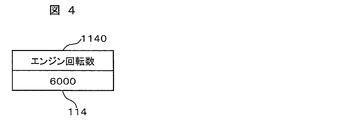
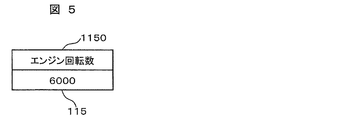
- the data storage area 111 stores an update type table 112 for CPU 1 described later in FIG. 2, an update type table 113 for CPU 2 in FIG. 3, an engine speed 114 for CPU 1 in FIG. 4, and an engine speed 115 for CPU 2 in FIG. To do.
- the first embodiment uses two arithmetic devices, two update type tables, and two engine speeds, but is not limited thereto. For example, there may be three arithmetic units, three update type tables, three engine speeds, four arithmetic units, four update type tables, and four engine speeds.
- FIG. 3 is an example of the update type table 113 for CPU2.
- the items in this table are the same as the update type table 112 for CPU1.
- the CPU 2 update type table is used in the first embodiment, but the present invention is not limited to this.
- the configuration of the table may be different, may not be implemented as a table, or may not match the CPU 1 update type table.
- the CPU 2 update type table 113 indicates data to be synchronized by the arithmetic unit 102.
- FIG. 4 is an example of a variable of the engine speed 114 for the CPU 1.
- the CPU 1 engine speed 1140 stores the engine speed.
- the engine speed 1140 for the CPU 1 is used in the first embodiment, but is not limited thereto.
- FIG. 5 is an example of a variable of the engine speed 115 for the CPU 2.
- the CPU 2 engine speed 1150 stores the engine speed.
- the engine speed 1150 for the CPU 1 is used in the first embodiment, but is not limited thereto.
- it may be mounted as a structure that is not a single variable but a collection of a plurality of data, and may not be the same mounting method as the CPU 1 engine speed 114.
- FIG. 6 is an operation flow of the engine rotation calculation unit 105. Hereinafter, each step of FIG. 6 will be described. (FIG.
- the engine speed calculation unit 105 calculates the engine speed based on the crank angle sensor 117. (FIG. 6: Step 105001) The engine speed calculation unit 105 calls the data update processing unit 107 using the calculated engine speed as an argument, and stores the engine speed in the shared memory 103.
- the engine speed is calculated, and the engine speed is stored in the shared memory.
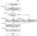
- FIG. 7 is an operation flow of the data update processing unit 107.
- the data update processing unit 107 calls the core determination processing unit 110 and acquires the CPU number that is executing the data update processing unit 107.
- the data update processing unit 107 proceeds to step 107002 when the acquired CPU number is 1, and proceeds to step 107003 when the CPU number is other than 1, for example, 2.
- the data update processing unit 107 stores the engine speed of the argument in the CPU 1 engine speed 114 of the shared memory 103.
- the two arithmetic devices of the first embodiment do not execute the in-core exclusive control because the storage processing in the engine speed 114 for the CPU 1 can be updated by the arithmetic device 1 command.
- In-core exclusive control is exclusive control that can prevent data conflicts within the same CPU, such as the OSEK OS Resource defined by OSEK / VDX. Even if the instruction cannot be updated by the instruction of the arithmetic unit 1, the in-core exclusive control does not have to be executed even in a system where it is determined that preemption does not occur during the execution of step 107002.
- one variable of the engine speed 114 for the CPU 1 is updated.
- the present invention is not limited to this. For example, two or more variables may be updated.
- Step 107003 The data update processing unit 107 stores the engine speed of the argument in the CPU 2 engine speed 115 of the shared memory 103.
- the two arithmetic devices of the first embodiment do not execute the in-core exclusive control because the storage processing in the engine speed 115 for the CPU 2 can be updated by the arithmetic device 1 command.
- one variable of the engine speed 115 for the CPU 2 is updated, but this is not limited to the same as in the step 107002. (FIG. 7: Step 107004)
- the data update processing unit 107 searches for a column that is equal to the data ID indicating the engine speed from the data ID of the update type table in order to notify the other arithmetic unit of the update of the engine speed 114 for the CPU 1, Update the update core.
- the engine speed is stored in the shared memory in accordance with the CPU number, the update type table is updated, and an interrupt signal is input to another CPU.
- the other CPUs can refer to the latest value of the updated engine speed without waiting time.
- This interrupt signal may be set to the highest priority, for example.
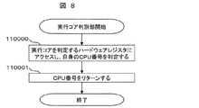
- FIG. 8 is an operation flow of the execution core determination unit 110.
- the execution core determination unit 110 accesses a hardware register for determining an execution core, determines its own CPU number, and acquires it.
- the CPU number is determined by the hardware register in the first embodiment, but the present invention is not limited to this.
- the execution core determination unit 110 returns the acquired CPU number.
- the CPU number of the arithmetic unit that is executing the execution core determination unit can be acquired.
- FIG. 9 is an operation flow of the data synchronization unit 109.
- the data synchronization unit 109 calls the core determination processing unit 110 and acquires the CPU number that is executing the data update processing unit 107.
- the data synchronization unit 109 proceeds to step 109002 if the acquired CPU number is 1, and proceeds to step 109003 if the CPU number is other than 1, for example, 2.
- the data synchronization unit 109 refers to the CPU 1 update type table 112 in the shared memory 103.
- the activation method is not limited to this.
- the data reference processing unit is executed before the next data update processing unit is executed, and the data synchronization unit is called after the data update processing unit is executed and before the data reference processing unit is executed.
- exclusive control may not be used.
- the interrupt signal is not the highest priority interrupt signal, exclusive control may not be used if the data synchronization unit can be activated before the next update process is executed.
- the data update processing unit and the data reference processing unit are executed in the same cycle, or the data update processing unit is executed in a cycle shorter than that of the data reference processing unit.
- the data synchronization unit 109 refers to the update core of the type whose update flag in the update type table indicates 1, and identifies the updated CPU. As a result, the latest value data is known, and the target data value is copied to its own data. In the first embodiment, since the update core is 1 as shown in FIG. 3, the value of the engine speed 114 for the CPU 1 is copied to the engine speed 115 for the CPU 2. (FIG. 9: Step 109006) The data synchronization unit 109 clears the update flag of its own update type table corresponding to the copied data to 0, and proceeds to step 109004.
- the data values for each core can be matched without using exclusive control between cores.
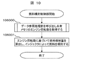
- FIG. 10 is an operation flow of the fuel injection control unit 106.
- Step 106000 The fuel injection control unit 106 calls the data reference processing unit and acquires the engine speed of the shared memory.
- Step 106001 The fuel injection control unit 106 calculates a fuel injection amount based on the acquired engine speed, and injects fuel with the injector.
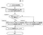
- FIG. 11 is an operation flow of the data reference processing unit 108.
- the data reference processing unit 108 calls the core discrimination processing unit 110 and acquires the CPU number that is executing the data update processing unit 107.
- the data reference processing unit 108 proceeds to step 108002 if the acquired CPU number is 1, and proceeds to step 108003 if the CPU number is other than 1, for example, 2.
- the data reference processing unit 108 acquires the engine speed from the CPU1 engine speed 114 of the shared memory 103.
- the two arithmetic devices according to the first embodiment do not execute the in-core exclusive control because the processing acquired from the CPU 1 engine speed 114 can be updated by the arithmetic device 1 command. Even if the instruction cannot be updated by the instruction of the arithmetic unit 1, the in-core exclusive control does not have to be executed even in a system in which it is determined that preemption does not occur during execution of step 107802.
- one variable of the engine speed 114 for the CPU 1 is updated.
- the present invention is not limited to this. For example, two or more variables may be updated. At this time, in the case of a system in which it is determined that preemption does not occur during execution of step 108002, it is not necessary to execute in-core exclusive control.
- the data reference processing unit 108 acquires the engine speed from the CPU 2 engine speed 115 of the shared memory 103.
- the two arithmetic devices of the first embodiment do not execute the in-core exclusive control because the storage processing in the engine speed 115 for the CPU 2 can be updated by the arithmetic device 1 command.
- one variable of the engine speed 115 for the CPU 2 is updated, but this is not limited to this as in the case of step 108002.
- the data reference processing unit 108 returns the acquired engine speed and ends the process.
- the engine speed can be acquired from the shared memory.
- the update type table is used for notification of updated data, but the present invention is not limited to this.
- the interrupt signal itself may have a meaning that data has been updated, or a dedicated data synchronization unit may be mounted for each data to be updated.
- the data synchronization unit is activated by an interrupt signal, but the present invention is not limited to this.
- the execution core determination unit is executed by the data update processing unit and the data reference processing unit, but the present invention is not limited to this.
- the arithmetic unit that executes the engine rotation calculation unit and the fuel injection control unit is a system that does not change during execution, it may be executed only once at the time of initialization.
- data can be updated and referenced using a shared memory without using exclusive control. It is suitable for a vehicle system that needs to pass data with. For example, in engine control, calculations necessary for injector control are executed in synchronization with engine rotation. Since the calculation cycle becomes shorter as the engine speed increases, it is preferable to use the first embodiment that can exclude exclusive control.
- the data synchronization unit by starting the data synchronization unit with the highest priority interrupt signal, it becomes easy to start the data synchronization unit before the data update processing unit is executed next time. It is possible to reduce development man-hours during development. This is suitable for a vehicle system in which the data update processing unit is activated at regular intervals.
- an application such as an engine rotation calculation processing unit or a fuel injection control unit uses which data update processing unit or data reference processing unit is used to determine which arithmetic device is executed. Data can be updated and referenced without awareness. Therefore, even if the arithmetic unit executed at the time of new vehicle model development is changed, the number of parts to be changed is small, so that the software development man-hours can be reduced.
- the second embodiment is an example in which three arithmetic units are provided, and the data synchronizer synchronizes data that is not used for calculation in the control calculation of the engine rotation calculation unit and the control calculation of the fuel injection control unit.
- the data synchronizer synchronizes data that is not used for calculation in the control calculation of the engine rotation calculation unit and the control calculation of the fuel injection control unit.
- three examples of arithmetic devices are shown, but this embodiment can be applied if there are a plurality of arithmetic devices.
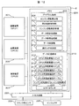
- FIG. 12 is a configuration diagram of the engine control ECU 2 of the vehicle system according to Embodiment 2 of the present invention.
- the engine control ECU includes an arithmetic device 201 (CPU1), an arithmetic device 202 (CPU2), an arithmetic device 203 (CPU3), a memory 204, an input / output circuit 223, a crank angle sensor 224, and an injector 225.
- the memory 204 includes a program area 205 and a data storage area 213.
- the program area 205 includes an engine speed calculation unit 206, a fuel injection control unit 207, an engine speed diagnosis unit 208, a data update processing unit 209, a data reference processing unit 210, The data synchronization unit 211 and the execution core determination unit 212 are included.
- the data storage area 213 includes the latest value switch 214 for CPU 1 described later in FIG. 13, the latest value switch 215 for CPU 2 in FIG. 14, the latest value switch 216 for CPU 3 in FIG. 15, and the update type for CPU 1 as in the first embodiment.
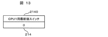
- FIG. 13 shows an example of the latest value switch 214 for CPU1. If the value of the latest value switch 2140 for CPU 1 is 0, the latest value of the engine speed is stored in the engine speed A 220, and if it is 1, the engine speed B 221 is stored. The value of the latest value switch 2140 for CPU 1 is updated when the arithmetic unit 201 executes the data update processing unit or executes the data synchronization unit.
- FIG. 15 shows an example of the latest value switch 216 for the CPU 3. If the value of the latest value switch 2160 for the CPU 3 is 0, the latest value of the engine speed is stored in the engine speed A220, and if it is 1, the engine speed B221 is stored. The value of the latest value switch 2160 for CPU 3 is updated when the arithmetic device 203 executes the data update processing unit or executes the data synchronization unit.
- latest value switch 214 for CPU1 the latest value switch 215 for CPU2, and the latest value switch 216 for CPU3 may be mounted not only in an area in the memory 204 but also by hardware outside the memory 204.
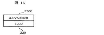
- FIG. 16 shows an example of the engine speed A220
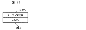
- FIG. 17 shows an example of the engine speed B221.
- the engine speed A220 and the engine speed B221 are always the targets for which the latest value is stored and referred to, and the other that does not store the latest value is the target to be updated.
- the updated value stores the latest value by the next update. That is, one of the two values alternately becomes the latest value, and the latest value is indicated by the latest value switch.
- the pointer of the latest engine speed and the buffer of the engine speed to be updated next time may be indicated by using a pointer without using a switch.
- the pointer is a logical value indicating the position of the memory or register, and an abnormality indicating an incorrect position may occur. In this embodiment, since a switch is used without using a pointer, reliability can be improved.
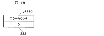
- FIG. 18 shows an example of the error counter 222.
- the value of the error counter 2220 is a value that is counted up when the engine speed diagnosis unit determines that the engine speed value is abnormal.
- the engine rotation calculation unit 206 is the same as the operation of the engine rotation calculation unit 105 shown in FIG. 6, and the fuel injection control unit 207 is the same as the operation of the fuel injection control unit 106 shown in FIG.
- the data synchronization unit 211 is an operation obtained by extending the operation of the data synchronization unit 109 shown in FIG. 9 so that it can be performed by three CPUs.
- the data synchronization unit determines whether or not the latest value switch of each CPU has been updated by referring to the update type table of each CPU, and copies the updated latest value switch value to its own latest value switch.
- the data synchronization unit 211 executed by the arithmetic device 202 copies the value of the latest value switch 214 for CPU1 to the latest value switch 215 for CPU2,
- the data synchronization unit 211 executed by the arithmetic unit 203 copies the value of the latest value switch 214 for CPU 1 to the latest value switch 216 for CPU 3.
- the execution core determination unit 212 is the same as the operation of the execution core determination unit 110 shown in FIG.
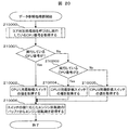
- FIG. 19 is an operation flow of the data update processing unit 209. Hereinafter, each step of FIG. 19 will be described.
- the data update processing unit 209 calls the core determination processing unit 212 and acquires the CPU number that is executing the data update processing unit 209.
- the data update processing unit 209 proceeds to step 209002 if the acquired CPU number is 1, and proceeds to step 209003 if the CPU number is other than 1, for example, 2 or 3.
- the data update processing unit 209 acquires the value of the latest value switch 214 for CPU1.
- the data update processing unit 209 proceeds to step 209004 when the acquired CPU number is 2, and proceeds to step 209005 when the CPU number is other than 2, for example, 3.
- the data update processing unit 209 acquires the value of the latest value switch 215 for the CPU 2.
- the data update processing unit 209 acquires the value of the latest value switch 216 for the CPU 3.
- the data update processing unit 209 stores the engine speed in the engine speed buffer according to the switch value. For example, when the value of the switch is 0, the latest engine speed is stored in the engine speed B221.
- the data update processing unit 209 updates the value of its own switch.
- the data update processing unit 209 updates the update flag and update core of the data ID in the other update type table. For example, when the value of the latest value switch 214 for CPU 1 is updated, the update flag and update of the update type table 218 for CPU 2 and the update type table 219 for CPU 3 corresponding to the data ID indicating the latest value switch for CPU 1 of the engine speed are updated. Update the CPU. (FIG. 19: Step 209090)
- the data update processing unit 209 inputs an interrupt signal to another CPU. In the second embodiment, an interrupt signal is input and update is notified to other CPUs, but the present invention is not limited to this method.
- the engine speed of the shared memory can be updated.
- FIG. 20 is an operation flow of the data reference processing unit 210.
- the data reference processing unit 210 calls the core discrimination processing unit 212 and acquires the CPU number that is executing the data reference processing unit 210.
- the data reference processing unit 209 proceeds to step 210002 when the acquired CPU number is 1, and proceeds to step 210003 when the CPU number is other than 1, for example, 2 or 3.
- the data reference processing unit 210 acquires the value of the latest value switch 214 for the CPU 1.
- the data reference processing unit 210 proceeds to step 210004 when the acquired CPU number is 2, and proceeds to step 210005 when the CPU number is other than 2, for example, 3.
- the data reference processing unit 210 acquires the value of the latest value switch 215 for the CPU 2.
- the data reference processing unit 210 acquires the value of the latest value switch 216 for the CPU 3.
- the data reference processing unit 210 reads the engine speed from the engine speed buffer corresponding to the switch value. For example, when the value of the switch is 1, the latest engine speed is acquired from the engine speed B221.
- the engine speed of the shared memory can be acquired.
- FIG. 21 is an operation flow of the engine speed diagnosis unit 208.
- the engine speed diagnosis unit 208 calls the data reference processing unit 210 and acquires the engine speed stored in the shared memory.
- the engine speed diagnosis unit 208 proceeds to step 208002 if it is outside the normal value range for determining whether the value of the engine speed is within the normal value range, and ends the process if it is within the normal value range.
- the method for determining an abnormality is not limited to this.
- the engine speed diagnosis unit 208 taps the value of the error counter 222. For example, 1 is added to the value of the error counter 222. However, it is not limited to this.
- the value when data is multiplexed and the data is referred to, the value is read from the data indicated by the latest value switch, and when the data is updated, the value is written in the data value not indicated by the latest value switch.
- the CPU that has updated the data notifies the other CPUs of the data update without delay after the data update.
- the CPU that refers to the data can refer to the latest value without delay.
- a switch is used, but the present invention is not limited to this.
- the pointer may be implemented using a pointer indicating the latest value and a pointer indicating the update target, but using the switch without using the pointer can improve the reliability.
- the second embodiment even if there are three or more arithmetic devices, it is possible to update or refer to data using shared memory without using exclusive control. Thus, it is suitable for a vehicle system that needs to exchange data between a plurality of arithmetic devices at high speed.
Landscapes
- Engineering & Computer Science (AREA)
- Software Systems (AREA)
- Theoretical Computer Science (AREA)
- Physics & Mathematics (AREA)
- General Physics & Mathematics (AREA)
- General Engineering & Computer Science (AREA)
- Mechanical Engineering (AREA)
- Computational Mathematics (AREA)
- Mathematical Analysis (AREA)
- Mathematical Optimization (AREA)
- Pure & Applied Mathematics (AREA)
- Combined Controls Of Internal Combustion Engines (AREA)
Abstract
Description
図1は、本発明の実施の形態1に係る車両システムのエンジン制御ECU1の構成図である。エンジン制御ECU1は演算装置101(CPU1)、演算装置102(CPU2)、共有メモリ103、入出力回路116を備える。共有メモリ103としては、例えばデュアルポートRAM、高速アクセス可能なSDRAM等であってよい。また、エンジン制御ECU1にはクランク角センサ117や図示しないエンジンの吸入空気量センサ等の各種センサからの入力信号が入力され、エンジンに燃料を噴射するためのインジェクタ118等のアクチュエータを制御する。共有メモリ103はインジェクタ118等のアクチュエータの制御処理に関するプログラム領域104と、制御に必要なデータを二重に冗長化して記憶するためのデータ記憶領域111を有する。プログラム領域104は、クランク角センサからエンジン回転数を算出するためのエンジン回転算出部105、エンジンに燃料を噴射する期間やタイミングを演算するための燃料噴射制御部106、エンジン回転数等のデータをデータ記憶領域111に格納するためのデータ更新処理部107、エンジン回転数等のデータをデータ記憶領域111から取得するためのデータ参照処理部108、冗長化されたデータを複数のCPU間で同期させるためのデータ同期部109、データ更新処理やデータ参照処理を実行しているCPUを判別する実行コア判別部110を有する。データ記憶領域111は後述の図2で説明するCPU1用更新種別テーブル112、図3のCPU2用更新種別テーブル113、図4のCPU1用エンジン回転数114、図5のCPU2用エンジン回転数115を格納する。説明の都合上、実施の形態1では2つの演算装置、2つの更新種別テーブル、2つのエンジン回転数を用いるが、これに限らない。例えば、3つの演算装置、3つの更新種別テーブル、3つのエンジン回転数であっても良いし、4つの演算装置、4つの更新種別テーブル、4つのエンジン回転数であっても良い。
(図6:ステップ105000)
エンジン回転算出部105は、クランク角センサ117に基づいてエンジン回転数を算出する。
(図6:ステップ105001)
エンジン回転算出部105は、算出したエンジン回転数を引数としてデータ更新処理部107を呼び出し、エンジン回転数を共有メモリ103に格納する。
(図7:ステップ107000)
データ更新処理部107は、コア判別処理部110を呼び出し、データ更新処理部107を実行しているCPU番号を取得する。
(図7:ステップ107001)
データ更新処理部107は、取得したCPU番号が1である場合、ステップ107002へ進み、CPU番号が1以外、例えば2の場合はステップ107003へ進む。
(図7:ステップ107002)
データ更新処理部107は、引数のエンジン回転数を共有メモリ103のCPU1用エンジン回転数114に格納する。実施の形態1の2つの演算装置はCPU1用エンジン回転数114への格納処理を演算装置1命令で更新可能であるためコア内排他制御を実行しない。コア内排他制御とは、OSEK/VDXが定義したOSEK OSのResourceといった同じCPU内でデータの競合を防げる排他制御である。もし、演算装置1命令で更新不可能であっても、ステップ107002実行中にプリエンプションが起こらないことが決まっているシステムである場合もコア内排他制御を実行しなくてよい。説明の都合上、実施の形態1ではCPU1用エンジン回転数114という1つの変数を更新しているが、これに限らない。例えば、2つ以上の変数を更新してもよい。このとき、ステップ107002実行中にプリエンプションが起こらないことが決まっているシステムである場合はコア内排他制御を実行しなくてよい。しかし、プリエンプションが起こる場合は、コア内排他制御を実行する必要がある。また、TDMA形式のスケジューリングを備えたマルチコアOSを用いれば、同じ時間に同じデータ種別に対するデータ更新処理とデータ参照処理を入れないようにスケジューリングすればよいので、簡単に適用できる。
(図7:ステップ107003)
データ更新処理部107は、引数のエンジン回転数を共有メモリ103のCPU2用エンジン回転数115に格納する。実施の形態1の2つの演算装置はCPU2用エンジン回転数115への格納処理を演算装置1命令で更新可能であるためコア内排他制御を実行しない。説明の都合上、実施の形態1ではCPU2用エンジン回転数115という1つの変数を更新しているが、ステップ107002と同様にこれに限らない。
(図7:ステップ107004)
データ更新処理部107は、他の演算装置にCPU1用エンジン回転数114の更新を知らせるために、更新種別テーブルのデータIDからエンジン回転数を示すデータIDと等しい列を探し、対象の更新フラグと更新コアを更新する。実施の形態1では、CPU1がエンジン回転数データの更新を行い、CPU2がエンジン回転数データの参照を行うよう割り当てられているので、更新する更新種別テーブルはCPU2用更新種別テーブルだけである。実施の形態1では更新フラグが0のときはデータが更新されていないことを示し、1のときはデータが更新されたことを示すが、二値データに限らず、任意の変数でもよい。また、実施の形態1では更新コアにCPU番号を格納するが、演算装置を識別できればこれに限らない。
(図7:ステップ107005)
データ更新処理部107は、他のCPU、本実施の形態では演算装置102に割り込み信号を入れ、処理を終了する。
(図8:ステップ110000)
実行コア判別部110は、実行コアを判定するハードウェアレジスタにアクセスし、自身のCPU番号を判定し、取得する。説明の都合上、実施の形態1ではハードウェアレジスタによってCPU番号を判定しているが、これに限らない。
(図8:ステップ110001)
実行コア判別部110は、取得したCPU番号をリターンする。
(図9:ステップ109000)
データ同期部109は、コア判別処理部110を呼び出し、データ更新処理部107を実行しているCPU番号を取得する。
(図9:ステップ109001)
データ同期部109は、取得したCPU番号が1である場合、ステップ109002へ進み、CPU番号が1以外、例えば2の場合はステップ109003へ進む。
(図9:ステップ109002)
データ同期部109は、共有メモリ103のCPU1用更新種別テーブル112を参照する。
(図9:ステップ109003)
データ同期部109は、共有メモリ103のCPU2用更新種別テーブル113を参照する。ステップ109002と同様に排他制御を使用しない。また起動方法もこれに限らない。
(図9:ステップ109004)
データ同期部109は、参照している更新種別テーブルの更新フラグが1の種別がある、すなわち更新を示す列がある場合、ステップ109005へ進み、更新を示す列がない場合は処理を終了する。実施の形態1では更新フラグによってデータの更新を通知しているが、これに限らない。例えば、割り込み信号そのものにデータが更新された意味を持たせても良いし、更新するデータごとに専用のデータ同期部を実装してもよい。
(図9:ステップ109005)
データ同期部109は、更新種別テーブルの更新フラグが1を示す種別の更新コアを参照し、更新したCPUを識別する。これによって最新値のデータがわかり、対象のデータ値を自身のデータにコピーする。実施の形態1では、図3に示すように更新コアが1であるため、CPU1用エンジン回転数114の値をCPU2用エンジン回転数115にコピーする。
(図9:ステップ109006)
データ同期部109は、コピーしたデータに対応する自身の更新種別テーブルの更新フラグを0にクリアし、ステップ109004に進む。
(図10:ステップ106000)
燃料噴射制御部106は、データ参照処理部を呼び出し、共有メモリのエンジン回転数を取得する。
(図10:ステップ106001)
燃料噴射制御部106は、取得したエンジン回転数に基づいて燃料噴射量を算出し、インジェクタによって燃料を噴射する。
(図11:ステップ108000)
データ参照処理部108は、コア判別処理部110を呼び出し、データ更新処理部107を実行しているCPU番号を取得する。
(図11:ステップ108001)
データ参照処理部108は、取得したCPU番号が1である場合、ステップ108002へ進み、CPU番号が1以外、例えば2の場合はステップ108003へ進む。
(図11:ステップ108002)
データ参照処理部108は、共有メモリ103のCPU1用エンジン回転数114からエンジン回転数を取得する。実施の形態1の2つの演算装置はCPU1用エンジン回転数114から取得する処理を演算装置1命令で更新可能であるためコア内排他制御を実行しない。もし、演算装置1命令で更新不可能であっても、ステップ107802実行中にプリエンプションが起こらないことが決まっているシステムである場合もコア内排他制御を実行しなくてよい。説明の都合上、実施の形態1ではCPU1用エンジン回転数114という1つの変数を更新しているが、これに限らない。例えば、2つ以上の変数を更新してもよい。このとき、ステップ108002実行中にプリエンプションが起こらないことが決まっているシステムである場合はコア内排他制御を実行しなくてよい。しかし、プリエンプションが起こる場合は、コア内排他制御を実行する必要がある。
(図11:ステップ108003)
データ参照処理部108は、共有メモリ103のCPU2用エンジン回転数115からエンジン回転数を取得する。実施の形態1の2つの演算装置はCPU2用エンジン回転数115への格納処理を演算装置1命令で更新可能であるためコア内排他制御を実行しない。説明の都合上、実施の形態1ではCPU2用エンジン回転数115という1つの変数を更新しているが、ステップ108002と同様にこれに限らない。
(図11:ステップ108004)
データ参照処理部108は、取得したエンジン回転数をリターンし、処理を終了する。
実施の形態2は3つの演算装置を備え、エンジン回転算出部の制御演算と燃料噴射制御部の制御演算で演算に使用しないデータをデータ同期部が同期する例である。本実施の形態では、演算装置が3つの例を示しているが、複数の演算装置が存在すれば本実施の形態は適用可能である。
(図19:ステップ209000)
データ更新処理部209は、コア判別処理部212を呼び出し、データ更新処理部209を実行しているCPU番号を取得する。
(図19:ステップ209001)
データ更新処理部209は、取得したCPU番号が1である場合、ステップ209002へ進み、CPU番号が1以外、例えば2や3の場合はステップ209003へ進む。
(図19:ステップ209002)
データ更新処理部209は、CPU1用最新値スイッチ214の値を取得する。
(図19:ステップ209003)
データ更新処理部209は、取得したCPU番号が2である場合、ステップ209004へ進み、CPU番号が2以外、例えば3の場合はステップ209005へ進む。
(図19:ステップ209004)
データ更新処理部209は、CPU2用最新値スイッチ215の値を取得する。
(図19:ステップ209005)
データ更新処理部209は、CPU3用最新値スイッチ216の値を取得する。
(図19:ステップ209006)
データ更新処理部209は、スイッチの値に応じたエンジン回転数のバッファにエンジン回転数を格納する。例えば、スイッチの値が0である場合、エンジン回転数B221に最新値であるエンジン回転数を格納する。
(図19:ステップ209007)
データ更新処理部209は、自身のスイッチの値を更新する。例えば、演算装置201がエンジン回転数B221を更新した場合、CPU1用最新値スイッチ214の値を1に更新する。
(図19:ステップ209008)
データ更新処理部209は、他の更新種別テーブルのデータIDの更新フラグと更新コアを更新する。例えば、CPU1用最新値スイッチ214の値が更新された場合、エンジン回転数のCPU1用最新値スイッチを示すデータIDに応じたCPU2用更新種別テーブル218とCPU3用更新種別テーブル219の更新フラグと更新CPUを更新する。
(図19:ステップ209009)
データ更新処理部209は、他のCPUに割り込み信号を入れる。実施の形態2では割り込み信号を入力し、他のCPUに更新を通知するが、この方法に限らない。
(図20:ステップ210000)
データ参照処理部210は、コア判別処理部212を呼び出し、データ参照処理部210を実行しているCPU番号を取得する。
(図20:ステップ210001)
データ参照処理部209は、取得したCPU番号が1である場合、ステップ210002へ進み、CPU番号が1以外、例えば2や3の場合はステップ210003へ進む。
(図20:ステップ210002)
データ参照処理部210は、CPU1用最新値スイッチ214の値を取得する。
(図20:ステップ210003)
データ参照処理部210は、取得したCPU番号が2である場合、ステップ210004へ進み、CPU番号が2以外、例えば3の場合はステップ210005へ進む。
(図20:ステップ210004)
データ参照処理部210は、CPU2用最新値スイッチ215の値を取得する。
(図20:ステップ210005)
データ参照処理部210は、CPU3用最新値スイッチ216の値を取得する。
(図20:ステップ210006)
データ参照処理部210は、スイッチの値に応じたエンジン回転数のバッファからエンジン回転数を読み出す。例えば、スイッチの値が1である場合、エンジン回転数B221から最新値であるエンジン回転数を取得する。
(図21:ステップ208000)
エンジン回転数診断部208は、データ参照処理部210を呼び出し、共有メモリに格納されているエンジン回転数を取得する。
(図21:ステップ208001)
エンジン回転数診断部208は、エンジン回転数の値が正常値範囲に入っているかを判定する正常値範囲外である場合はステップ208002に進み、正常値範囲内である場合は処理を終了する。しかし、異常と判定する方法はこれに限らない。
(図21:ステップ208002)
エンジン回転数診断部208は、エラーカウンタ222の値をカウントタップする。例えば、エラーカウンタ222の値に1を加算する。しかし、これに限らない。
101、102 演算装置
103 共有メモリ
104 プログラム領域
105 エンジン回転算出部
106 燃料噴射制御部
107 データ更新処理部
108 データ参照処理部
109 データ同期部
111 データ記憶領域
112 CPU1用更新種別テーブル
113 CPU2用更新種別テーブル
114 CPU1用エンジン回転数
115 CPU2用エンジン回転数
Claims (12)
- 複数の演算装置と、前記複数の演算装置が共通にアクセスする共有データが冗長に格納される共有メモリとを備えた車両用制御装置であって、
前記共有メモリはプログラム領域と、データ領域と、を備え、
前記データ領域は、前記複数の演算装置それぞれに対応して前記共有データを冗長に格納する複数のデータバッファを備え、
前記プログラム領域は、前記複数の演算装置中の一の演算装置が前記一の演算装置に対応するデータバッファを更新して新たな共有データを格納し、前記複数の演算装置中の他の制御装置に共有データの更新を通知するデータ更新処理部と、
前記他の演算装置が前記通知後に、前記一の演算装置に対応するデータバッファの共有データを前記他の演算装置に対応するデータバッファにコピーするデータ同期部と、
前記他の演算装置が前記他の演算装置に対応するデータバッファを参照するデータ参照処理部と、を備えることを特徴とする車両用制御装置。 - 複数の演算装置と、前記複数の演算装置が共通にアクセスする共有データが冗長に格納される共有メモリとを備えた車両用制御装置であって、
前記共有メモリはプログラム領域と、データ領域と、を備え、
前記データ領域は、前記共有データを冗長に格納する複数のデータバッファと、
前記複数の演算装置それぞれに対応して設けられた、前記複数のデータバッファ中で最後に更新されたデータバッファを示す複数の最新値スイッチと、を備え、
前記プログラム領域は、前記複数の演算装置中の一の演算装置が前記一の演算装置に対応する最新値スイッチに基づいて前記複数のデータバッファ中の一のデータバッファを更新して新たな共有データを格納し、前記複数の演算装置中の他の制御装置に共有データの更新を通知するデータ更新処理部と、
前記通知後に前記一の演算装置に対応する最新値スイッチの値を前記他の制御装置に対応した最新値スイッチにコピーするデータ同期部と、
前記他の演算装置が前記他の制御装置に対応した最新値スイッチに基づいて前記複数のデータバッファ中の一のデータバッファを参照するデータ参照処理部と、を備えることを特徴とする車両用制御装置。 - 前記データ領域は、前記複数のデータバッファの種別、変更有無、変更演算装置識別子の情報を含み、前記複数の演算装置の数以上に多重化した更新種別テーブルを備えることを特徴とする請求項1または2いずれか一項に記載の車両用制御装置。
- 前記共有データは車載機器の制御に必要な制御値であることを特徴とする請求項1または2記載の車両用制御装置。
- 前記共有データには、制御値を格納するデータバッファを特定できる情報を格納することを特徴する請求項4記載の車両用制御装置。
- 処理を実行している演算装置を識別し、該演算装置の識別子を返すコア判別部を備えることを特徴とする請求項1または2いずれか一項に記載の車両用制御装置。
- 前記データ更新処理部は、前記コア判別部により取得した演算装置識別子に応じて、共有データを更新する対象となるデータバッファを切り替え、
前記データ参照処理部は、前記コア判別部により取得した演算装置識別子に応じて、共有データを参照する対象となるデータバッファを切り替えることを特徴とする請求項6記載の車両用制御装置。 - 前記データ更新処理部は、共有データの種別と、共有データの更新の有無と、前記一の演算装置を表す識別子と、が含まれる更新種別テーブルを変更することで、前記通知を行うことを特徴とする請求項3記載の車両用制御装置。
- 前記通知は前記他の演算装置への割り込み信号を含むことを特徴とする請求項1または2いずれか一項記載の車両用制御装置。
- 前記データ更新処理部が一度実行され、同じ共有データを更新する次の前記データ更新処理部が実行される時間よりも、短い時間の間に前記データ同期部の実行が完了することを特徴とする請求項1または2いずれか一項記載の車両用制御装置。
- 前記データ同期部は、前記更新種別テーブルの種別から更新された共有データの種別を特定し、前記更新種別テーブルの変更有無からコピーする必要があるかどうかを判定し、前記更新種別テーブルの識別子から、コピー元となる前記データバッファを特定し、特定した前記データバッファの値を、自身の演算装置が前記データバッファにコピーすることを特徴とする請求項8記載の車両用制御装置。
- 前記データ更新処理部と、前記データ同期部と、前記データ参照処理部は、前記複数の演算装置の中で、実行される演算装置が予め決められていることを特徴とする請求項1または2いずれか一項記載の車両用制御装置。
Priority Applications (3)
| Application Number | Priority Date | Filing Date | Title |
|---|---|---|---|
| DE112013001146.8T DE112013001146B4 (de) | 2012-02-23 | 2013-01-28 | Steuervorrichtung für ein Fahrzeug |
| CN201380008189.2A CN104094233B (zh) | 2012-02-23 | 2013-01-28 | 车辆用控制装置 |
| US14/379,649 US9547492B2 (en) | 2012-02-23 | 2013-01-28 | Arithmetic units accessing redundantly stored data in shared memory as part of a control device for a vehicle |
Applications Claiming Priority (2)
| Application Number | Priority Date | Filing Date | Title |
|---|---|---|---|
| JP2012-036924 | 2012-02-23 | ||
| JP2012036924A JP5816572B2 (ja) | 2012-02-23 | 2012-02-23 | 車両用制御装置 |
Publications (1)
| Publication Number | Publication Date |
|---|---|
| WO2013125294A1 true WO2013125294A1 (ja) | 2013-08-29 |
Family
ID=49005487
Family Applications (1)
| Application Number | Title | Priority Date | Filing Date |
|---|---|---|---|
| PCT/JP2013/051689 Ceased WO2013125294A1 (ja) | 2012-02-23 | 2013-01-28 | 車両用制御装置 |
Country Status (5)
| Country | Link |
|---|---|
| US (1) | US9547492B2 (ja) |
| JP (1) | JP5816572B2 (ja) |
| CN (1) | CN104094233B (ja) |
| DE (1) | DE112013001146B4 (ja) |
| WO (1) | WO2013125294A1 (ja) |
Families Citing this family (23)
| Publication number | Priority date | Publication date | Assignee | Title |
|---|---|---|---|---|
| JP6160571B2 (ja) | 2014-07-18 | 2017-07-12 | 株式会社デンソー | データ処理装置 |
| WO2016042588A1 (ja) * | 2014-09-17 | 2016-03-24 | 三菱電機株式会社 | 車載制御装置及びこの車載制御装置のシミュレーション装置 |
| JP6281463B2 (ja) | 2014-10-03 | 2018-02-21 | 株式会社デンソー | 制御装置 |
| KR102285749B1 (ko) | 2014-11-10 | 2021-08-05 | 삼성전자주식회사 | 세마포어 기능을 갖는 시스템 온 칩 및 그것의 세마포어 구현 방법 |
| JP6284903B2 (ja) * | 2015-05-18 | 2018-02-28 | 国立大学法人名古屋大学 | 通信装置及び通信制限プログラム |
| JP2017097633A (ja) * | 2015-11-25 | 2017-06-01 | 日立オートモティブシステムズ株式会社 | 車両制御装置 |
| US9537914B1 (en) | 2015-12-01 | 2017-01-03 | International Business Machines Corporation | Vehicle domain multi-level parallel buffering and context-based streaming data pre-processing system |
| JP6512087B2 (ja) | 2015-12-09 | 2019-05-15 | 株式会社デンソー | 車両用制御装置 |
| JP6838222B2 (ja) * | 2016-04-28 | 2021-03-03 | 日立Astemo株式会社 | 車両制御装置、及び車両システム |
| JP6380461B2 (ja) * | 2016-06-02 | 2018-08-29 | 住友電気工業株式会社 | 中継装置、プログラム更新システム、およびプログラム更新方法 |
| JP6895719B2 (ja) * | 2016-06-24 | 2021-06-30 | 日立Astemo株式会社 | 車両制御装置 |
| JP2018163528A (ja) * | 2017-03-27 | 2018-10-18 | 日立オートモティブシステムズ株式会社 | 車両制御装置 |
| JP7042138B2 (ja) * | 2018-03-30 | 2022-03-25 | 日立Astemo株式会社 | 処理装置 |
| JP7147367B2 (ja) * | 2018-08-23 | 2022-10-05 | 富士通株式会社 | 制御装置及び制御プログラム |
| EP3624510A1 (en) * | 2018-09-17 | 2020-03-18 | KNORR-BREMSE Systeme für Nutzfahrzeuge GmbH | Apparatus and method for synchronizing end nodes |
| JP2022065218A (ja) * | 2019-03-05 | 2022-04-27 | 日立Astemo株式会社 | 車両制御装置 |
| JP2020177074A (ja) * | 2019-04-16 | 2020-10-29 | 株式会社デンソー | 車両用装置、車両用装置の制御方法 |
| JP7567171B2 (ja) * | 2020-02-27 | 2024-10-16 | マツダ株式会社 | 車載機器制御装置及び車両制御システム |
| JP7567172B2 (ja) * | 2020-02-27 | 2024-10-16 | マツダ株式会社 | 車載機器制御装置 |
| JP7532806B2 (ja) * | 2020-02-27 | 2024-08-14 | マツダ株式会社 | 車載機器制御装置及び車両制御システム |
| JP2021152338A (ja) * | 2020-03-24 | 2021-09-30 | 日立Astemo株式会社 | 制御装置 |
| US12664062B2 (en) * | 2020-11-24 | 2026-06-23 | Autonetworks Technologies, Ltd. | Vehicle-mounted information processing apparatus and vehicle-mounted information processing method for converting between a virtual and physical address |
| JP7608970B2 (ja) * | 2020-11-24 | 2025-01-07 | 株式会社オートネットワーク技術研究所 | 車載情報処理装置及び車載情報処理方法 |
Citations (5)
| Publication number | Priority date | Publication date | Assignee | Title |
|---|---|---|---|---|
| JPH08106440A (ja) * | 1994-10-07 | 1996-04-23 | Hitachi Ltd | 分散共有メモリ計算機システム |
| JP2003203062A (ja) * | 2002-01-09 | 2003-07-18 | National Institute Of Advanced Industrial & Technology | リアルタイム処理用共有メモリ制御方式及び方法、並びにそれを実行させるためのプログラム |
| JP2004086615A (ja) * | 2002-08-27 | 2004-03-18 | Matsushita Electric Ind Co Ltd | バス通信装置 |
| JP2009037403A (ja) * | 2007-08-01 | 2009-02-19 | Fujitsu Ltd | マルチコアプロセッサにおけるコアメモリの有効活用方法 |
| JP2009110063A (ja) * | 2007-10-26 | 2009-05-21 | Toyota Motor Corp | 記憶装置、情報処理装置、データアクセス方法、プログラム |
Family Cites Families (12)
| Publication number | Priority date | Publication date | Assignee | Title |
|---|---|---|---|---|
| US5649102A (en) | 1993-11-26 | 1997-07-15 | Hitachi, Ltd. | Distributed shared data management system for controlling structured shared data and for serializing access to shared data |
| US5848241A (en) * | 1996-01-11 | 1998-12-08 | Openframe Corporation Ltd. | Resource sharing facility functions as a controller for secondary storage device and is accessible to all computers via inter system links |
| US5987376A (en) * | 1997-07-16 | 1999-11-16 | Microsoft Corporation | System and method for the distribution and synchronization of data and state information between clients in a distributed processing system |
| JP2001222466A (ja) * | 2000-02-10 | 2001-08-17 | Nec Corp | マルチプロセッサ・システムと共有メモリ制御システム及び方法並びに記録媒体 |
| US7406487B1 (en) * | 2003-08-29 | 2008-07-29 | Symantec Operating Corporation | Method and system for performing periodic replication using a log |
| CN100442248C (zh) * | 2004-11-16 | 2008-12-10 | 惠普开发有限公司 | 用于避免竞争的计算机系统同步单元 |
| US7496613B2 (en) * | 2006-01-09 | 2009-02-24 | International Business Machines Corporation | Sharing files among different virtual machine images |
| US7735051B2 (en) * | 2006-08-29 | 2010-06-08 | International Business Machines Corporation | Method for replicating and synchronizing a plurality of physical instances with a logical master |
| AU2007304895A1 (en) * | 2006-10-05 | 2008-04-10 | Waratek Pty Limited | Advanced contention detection |
| US20080120478A1 (en) * | 2006-10-05 | 2008-05-22 | Holt John M | Advanced synchronization and contention resolution |
| US8015375B1 (en) * | 2007-03-30 | 2011-09-06 | Emc Corporation | Methods, systems, and computer program products for parallel processing and saving tracking information for multiple write requests in a data replication environment including multiple storage devices |
| US9756125B2 (en) * | 2011-06-16 | 2017-09-05 | Telefonaktiebolaget Lm Ericsson (Publ) | Client and a server and methods thereof for data management relating to shared data storage |
-
2012
- 2012-02-23 JP JP2012036924A patent/JP5816572B2/ja not_active Expired - Fee Related
-
2013
- 2013-01-28 WO PCT/JP2013/051689 patent/WO2013125294A1/ja not_active Ceased
- 2013-01-28 US US14/379,649 patent/US9547492B2/en active Active
- 2013-01-28 CN CN201380008189.2A patent/CN104094233B/zh active Active
- 2013-01-28 DE DE112013001146.8T patent/DE112013001146B4/de active Active
Patent Citations (5)
| Publication number | Priority date | Publication date | Assignee | Title |
|---|---|---|---|---|
| JPH08106440A (ja) * | 1994-10-07 | 1996-04-23 | Hitachi Ltd | 分散共有メモリ計算機システム |
| JP2003203062A (ja) * | 2002-01-09 | 2003-07-18 | National Institute Of Advanced Industrial & Technology | リアルタイム処理用共有メモリ制御方式及び方法、並びにそれを実行させるためのプログラム |
| JP2004086615A (ja) * | 2002-08-27 | 2004-03-18 | Matsushita Electric Ind Co Ltd | バス通信装置 |
| JP2009037403A (ja) * | 2007-08-01 | 2009-02-19 | Fujitsu Ltd | マルチコアプロセッサにおけるコアメモリの有効活用方法 |
| JP2009110063A (ja) * | 2007-10-26 | 2009-05-21 | Toyota Motor Corp | 記憶装置、情報処理装置、データアクセス方法、プログラム |
Also Published As
| Publication number | Publication date |
|---|---|
| CN104094233B (zh) | 2018-12-07 |
| JP5816572B2 (ja) | 2015-11-18 |
| DE112013001146T5 (de) | 2014-11-06 |
| US9547492B2 (en) | 2017-01-17 |
| JP2013171547A (ja) | 2013-09-02 |
| CN104094233A (zh) | 2014-10-08 |
| US20150039865A1 (en) | 2015-02-05 |
| DE112013001146B4 (de) | 2024-09-26 |
Similar Documents
| Publication | Publication Date | Title |
|---|---|---|
| JP5816572B2 (ja) | 車両用制御装置 | |
| US6327668B1 (en) | Determinism in a multiprocessor computer system and monitor and processor therefor | |
| CN105094084B (zh) | 支持多核控制器上的相干数据访问的服务和系统 | |
| US20030079065A1 (en) | Methods and apparatus for providing data transfer control | |
| JP4920015B2 (ja) | 分散制御用制御ソフトウェアおよび電子制御装置 | |
| CN115061803B (zh) | 一种多核处理系统及其任务调度方法、芯片、存储介质 | |
| CN118377637B (zh) | 减少冗余缓存一致性操作的方法、装置、设备和存储介质 | |
| CN114780248B (zh) | 资源访问方法、装置、计算机设备及存储介质 | |
| US20040187118A1 (en) | Software barrier synchronization | |
| WO2017188109A1 (ja) | 車両制御装置、及び車両システム | |
| CN119179428A (zh) | 一种存储访问方法、处理器及电子设备 | |
| JP2008033893A (ja) | マルチプロセッサシステム及びマルチプロセッサシステムにおけるアクセス権設定方法 | |
| CN120950278A (zh) | 一种访问方法、装置、设备及计算机可读存储介质 | |
| JP7623887B2 (ja) | 電子制御装置及び異常判定方法 | |
| JP2015067107A (ja) | 車両用制御装置 | |
| JP5213485B2 (ja) | マルチプロセッサシステムにおけるデータ同期方法及びマルチプロセッサシステム | |
| WO2022009741A1 (ja) | 電子制御装置 | |
| JPH07287064A (ja) | レーダ信号処理装置 | |
| US7930523B2 (en) | Inter-CPU data transfer device | |
| US10269194B2 (en) | Multiprocessor system and vehicle control system | |
| US20120036337A1 (en) | Processor on an Electronic Microchip Comprising a Hardware Real-Time Monitor | |
| JP2013125305A (ja) | マルチプロセッサ装置 | |
| JP7518756B2 (ja) | 電子制御装置 | |
| JP6865707B2 (ja) | 車両用制御装置 | |
| JP2021060758A (ja) | 車両制御装置 |
Legal Events
| Date | Code | Title | Description |
|---|---|---|---|
| 121 | Ep: the epo has been informed by wipo that ep was designated in this application |
Ref document number: 13751104 Country of ref document: EP Kind code of ref document: A1 |
|
| WWE | Wipo information: entry into national phase |
Ref document number: 14379649 Country of ref document: US |
|
| WWE | Wipo information: entry into national phase |
Ref document number: 1120130011468 Country of ref document: DE Ref document number: 112013001146 Country of ref document: DE |
|
| 122 | Ep: pct application non-entry in european phase |
Ref document number: 13751104 Country of ref document: EP Kind code of ref document: A1 |