WO2013121712A2 - Projector and method of controlling projector - Google Patents
Projector and method of controlling projector Download PDFInfo
- Publication number
- WO2013121712A2 WO2013121712A2 PCT/JP2013/000446 JP2013000446W WO2013121712A2 WO 2013121712 A2 WO2013121712 A2 WO 2013121712A2 JP 2013000446 W JP2013000446 W JP 2013000446W WO 2013121712 A2 WO2013121712 A2 WO 2013121712A2
- Authority
- WO
- WIPO (PCT)
- Prior art keywords
- image
- distortion correction
- correction process
- projection
- section
- Prior art date
Links
- 238000000034 method Methods 0.000 title claims abstract description 240
- 230000008569 process Effects 0.000 claims abstract description 230
- 230000033001 locomotion Effects 0.000 claims description 25
- 230000009471 action Effects 0.000 description 22
- 238000001514 detection method Methods 0.000 description 22
- 238000003384 imaging method Methods 0.000 description 17
- 238000010586 diagram Methods 0.000 description 14
- 238000006243 chemical reaction Methods 0.000 description 13
- 230000006870 function Effects 0.000 description 13
- 230000008859 change Effects 0.000 description 10
- 230000003287 optical effect Effects 0.000 description 10
- 239000004973 liquid crystal related substance Substances 0.000 description 8
- 238000009434 installation Methods 0.000 description 6
- 238000005259 measurement Methods 0.000 description 6
- 239000003086 colorant Substances 0.000 description 4
- 239000000470 constituent Substances 0.000 description 2
- 230000007246 mechanism Effects 0.000 description 2
- 240000000136 Scabiosa atropurpurea Species 0.000 description 1
- 230000001133 acceleration Effects 0.000 description 1
- 230000008901 benefit Effects 0.000 description 1
- 230000005540 biological transmission Effects 0.000 description 1
- 230000015572 biosynthetic process Effects 0.000 description 1
- 230000008602 contraction Effects 0.000 description 1
- 238000004519 manufacturing process Methods 0.000 description 1
- 239000011159 matrix material Substances 0.000 description 1
- QSHDDOUJBYECFT-UHFFFAOYSA-N mercury Chemical compound [Hg] QSHDDOUJBYECFT-UHFFFAOYSA-N 0.000 description 1
- 229910052753 mercury Inorganic materials 0.000 description 1
- 230000007704 transition Effects 0.000 description 1
- 229910052724 xenon Inorganic materials 0.000 description 1
- FHNFHKCVQCLJFQ-UHFFFAOYSA-N xenon atom Chemical compound [Xe] FHNFHKCVQCLJFQ-UHFFFAOYSA-N 0.000 description 1
Images


Classifications
-
- G06T5/80—
-
- H—ELECTRICITY
- H04—ELECTRIC COMMUNICATION TECHNIQUE
- H04N—PICTORIAL COMMUNICATION, e.g. TELEVISION
- H04N9/00—Details of colour television systems
- H04N9/12—Picture reproducers
- H04N9/31—Projection devices for colour picture display, e.g. using electronic spatial light modulators [ESLM]
- H04N9/3179—Video signal processing therefor
- H04N9/3185—Geometric adjustment, e.g. keystone or convergence
-
- G—PHYSICS
- G06—COMPUTING; CALCULATING OR COUNTING
- G06T—IMAGE DATA PROCESSING OR GENERATION, IN GENERAL
- G06T5/00—Image enhancement or restoration
- G06T5/50—Image enhancement or restoration by the use of more than one image, e.g. averaging, subtraction
Definitions
- the present invention relates to a projector for projecting an image on a projection surface, and a method of controlling the projector.
- An advantage of some aspects of the invention is to provide a projector capable of performing the process of correcting the distortion of the projection image on the projection surface a plurality of times, and of reducing the load of the arithmetic processing related to the correction, and a method of controlling the projector.
- An aspect of the invention is directed to a projector including a projection unit adapted to project an image on a projection surface, a controller adapted to make the projection unit project a correcting image so as to be superimposed on the image presently projected if a start condition of a distortion correction process adapted to correct a distortion of the image projected by the projection unit is satisfied, and a correction unit adapted to perform the distortion correction process based on a state of the correcting image projected by the projection unit, and the controller makes the projection unit project the correcting image in a state in which a result of the distortion correction process fails to be reflected during a period from when the start condition of the distortion correction process is satisfied to when a condition for completing the distortion correction process is satisfied, and a period in which the correction unit performs the distortion correction process a plurality of times.
- the distortion correction process in the case of performing the distortion correction based on the state of the correcting image projected on the projection surface, the distortion correction process is not reflected on the correcting image, and the correcting image is projected until the distortion correction process is completed. Therefore, in the case of performing the distortion correction process a plurality of times, the distortion correction can be performed without adding the correction having already been performed. Thus, the process of correcting the distortion of the projection image on a projection surface can be performed a plurality of times, and at the same time, a load of arithmetic processing related to the correction can be reduced.
- Another aspect of the invention is directed to the projector according to the above aspect of the invention, wherein the controller makes the projection unit project the correcting image in the state in which the result of the distortion correction process fails to be reflected, and makes the projection unit update the projection state of the image presently projected so as to reflect the result of the distortion correction process if the correction unit performs the distortion correction process.
- the controller makes the projection unit project the correcting image in the state in which the result of the distortion correction process fails to be reflected, and makes the projection unit update the projection state of the image presently projected so as to reflect the result of the distortion correction process if the correction unit performs the distortion correction process.
- Still another aspect of the invention is directed to the projector according to the above aspect of the invention, wherein the controller makes the projection unit project the correcting image in the state in which the result of the distortion correction process fails to be reflected, and makes the projection unit update the projection state of the image presently projected so as to be an intermediate state between a state reflecting the distortion correction process and a state before reflecting the distortion correction process if the correction unit performs the distortion correction process.
- the result of the process is reflected on the projection state of the image every time the distortion correction process is performed, and at the same time, the level of the change in the image can be reduced.
- the distortion correction process is performed a plurality of times, it is possible to inform the user of the change in the image due to the distortion correction process in real time, and at the same time, the level of the change in the image is reduced to thereby prevent the uncomfortable feeling of the user.
- Yet another aspect of the invention is directed to the projector according to the above aspect of the invention, wherein the controller makes the projection unit project the correcting image in the state in which the result of the distortion correction process fails to be reflected, and performs projection of showing a shape of the image after the distortion correction process if the correction unit performs the distortion correction process.
- the controller makes the projection unit project the correcting image in the state in which the result of the distortion correction process fails to be reflected, and performs projection of showing a shape of the image after the distortion correction process if the correction unit performs the distortion correction process.
- Still yet another aspect of the invention is directed to the projector according to the above aspect of the invention, wherein the controller determines that the start condition of the distortion correction process is satisfied based on one of a movement of the projector and an external operation. According to this aspect of the invention, it is possible to promptly start the distortion correction process, and for example, perform the distortion correction process a plurality of times with a reduced processing load.
- Further another aspect of the invention is directed to the projector according to the above aspect of the invention, wherein the controller determines that the condition for completing the distortion correction process is satisfied based on one of a movement of the projector and an external operation. According to this aspect of the invention, by continuously performing the distortion correction process until the condition is satisfied, the distortion of the projection image can surely and accurately be corrected.
- Still further another aspect of the invention is directed to a method of controlling a projector including a projection unit adapted to project an image on a projection surface, the method including making the projection unit project a correcting image so as to be superimposed on the image presently projected if a start condition of a distortion correction process adapted to correct a distortion of the image projected by the projection unit is satisfied, performing the distortion correction process based on a state of the correcting image projected, and making the projection unit project the correcting image in a state in which a result of the distortion correction process fails to be reflected during a period from when the start condition of the distortion correction process is satisfied to when a condition for completing the distortion correction process is satisfied, and a period in which the distortion correction process is performed a plurality of times.
- the distortion correction process in the case of performing the distortion correction based on the state of the correcting image projected on the projection surface, the distortion correction process is not reflected on the correcting image, and the correcting image is projected until the distortion correction process is completed. Therefore, in the case of performing the distortion correction process a plurality of times, the distortion correction can be performed without adding the correction having already been performed. Thus, the process of correcting the distortion of the projection image on a projection surface can be performed a plurality of times, and at the same time, a load of arithmetic processing related to the correction can be reduced.
- Fig. 1 is a block diagram showing a configuration of a projector according to a first embodiment of the invention.
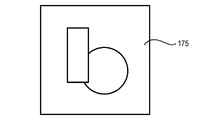
- Fig. 2A is an explanatory diagram showing an action of the projector projecting an image and a correction pattern, and showing an example of the image.
- Fig. 2B is an explanatory diagram showing an action of the projector projecting an image and a correction pattern, and showing an example of the correction pattern.
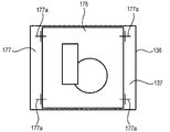
- Fig. 2C is an explanatory diagram showing an action of the projector projecting an image and a correction pattern, and showing an example in which a light modulation device draws the image and the correction pattern.
- Fig. 3A is an explanatory diagram showing an example of an action of the projector correcting the distortion of the projection image, and showing a projection example to the screen before the correction.
- Fig. 3B is an explanatory diagram showing an example of an action of the projector correcting the distortion of the projection image, and showing an example of the image formed in an image formable area.
- Fig. 3C is an explanatory diagram showing an example of an action of the projector correcting the distortion of the projection image, and showing a projection example to the screen after the correction.
- Fig. 4 is a flowchart showing an action of the projector according to the first embodiment.
- Fig. 5A is an explanatory diagram showing an example of an action of the projector correcting the distortion of the projection image in a second embodiment, and showing a projection example to the screen before the correction.
- Fig. 5A is an explanatory diagram showing an example of an action of the projector correcting the distortion of the projection image in a second embodiment, and showing a projection example to the screen before the correction.
- FIG. 5B is an explanatory diagram showing an example of an action of the projector correcting the distortion of the projection image in the second embodiment, and showing an example of the image formed in an image formable area.
- Fig. 5C is an explanatory diagram showing an example of an action of the projector correcting the distortion of the projection image in the second embodiment, and showing a projection example to the screen after the correction.
- Fig. 6 is a flowchart showing an action of the projector according to the second embodiment.
- Fig. 1 is a block diagram showing an overall configuration of a projector 100 according to the first embodiment.
- the projector 100 projects an image on a screen SC based on the image data stored in an image storage section 171 incorporated therein, or image data input from an external image supply device (not shown) such as a personal computer or various types of video players.
- the screen SC stands roughly upright, and the screen surface has a rectangular shape.
- the image data input to the projector 100 can be either of data of a moving image (a video) and data of a still image, and the projector 100 is capable of projecting the video on the screen SC and of continuously projecting the still image on the screen SC.
- the explanation is presented citing the case of projecting the image based on an analog signal input from an external image supply device via a cable 200 as an example.
- the projector 100 is composed of a projection section 101 (a projection unit) for performing optical image formation, and an image processing system for controlling overall function of the projector 100 to thereby electrically process the image signal.
- the projection section 101 is composed of a light source 140, a light modulation device 130, and a projection optical system 150.
- the light source 140 there can be used a xenon lamp, a super-high pressure mercury lamp, a light emitting diode (LED), a laser source, and so on.
- the light source 140 can also be provided with a reflector and an auxiliary reflector for guiding the light emitted by the light source 140 to the light modulation device 130, a light control element (not shown) for dimming the light emitted by the light source 140 on the path reaching the light modulation device 130, and so on.
- the light modulation device 130 receives a signal from an image processing system described later, and then modulates the light emitted by the light source 140 to thereby form the image light.
- the light modulation device 130 there can be cited, for example, a system using three transmissive or reflective liquid crystal light valves corresponding to the respective colors of RGB.
- the light emitted by the light source 140 is separated by a dichroic mirror and so on into the colored lights of R, G, and B, and then enters the light modulation device 130, the colored lights are modulated by the liquid crystal panels of the respective colors provided to the light modulation device 130, then the colored lights are combined by a cross dichroic prism, and then guided to the projection optical system 150.
- the configuration in which the light modulation device 130 is provided with the transmissive liquid crystal panels is adopted.
- the light modulation device 130 is driven by a light modulation device drive section 134 described later, and varies the light transmission in each of pixels arranged in a matrix to thereby form the image.
- the projection optical system 150 is provided with a zoom lens 151 for performing expansion and contraction of the image to be projected and adjustment of the focus, a zoom adjusting motor 152 for adjusting the level of the zoom, and a focus adjusting motor 153 for performing the focus adjustment.
- the light modulated by the light modulation device 130 enters the projection optical system 150, and then projected on the screen SC via the zoom lens 151 to thereby form the projection image.
- the zoom lens 151 is formed of a lens group including a plurality of lenses.
- the zoom adjusting motor 152 and the focus adjusting motor 153 drive the zoom lens 151 to perform the positioning of each of the lenses and the like to thereby perform the zoom control for expanding and contracting the projection image on the screen SC and the focus adjustment for appropriately form the projection image on the screen SC.
- the image processing system is configured with a CPU 120 for integrally controlling the entire projector 100, and an image processor 131 as the core constituents, and is provided with an A/D conversion section 110, the light modulation device drive section 134, a light source drive section 141, a lens drive section 154, a RAM 160, a ROM 170 including the image storage section 171 and a correction pattern storage section 172, an imaging section 180 having a CCD camera 181, a shot-image memory 182, a motion detection section 185, a remote controller control section 190, a remote controller 191, an operation section 195, and so on.
- These constituents constituting the image processing system are connected to each other via a bus 102.
- the A/D conversion section 110 is a device for performing the A/D conversion on the analog input signal input from the external image supply device described above via the cable 200, and outputs a digital signal obtained by the conversion to the image processor 131.
- the CPU 120 performs the image processing in the projector 100 together with the image processor 131.
- the CPU 120 is provided with a correction control section 122, a zoom ratio calculation section 123, a focal distance calculation section 124, a three-dimensional (3D) measurement section 125, and a projection angle calculation section 126 in addition to a projection control section 121 for performing the control related to the projection by the projector 100.
- These sections are each realized by the CPU 120 performing a program previously stored in the ROM 170.
- the CPU 120 functions as a controller, and in particular the function of the projection control section 121 corresponds to the controller.
- the image processor 131 is provided with a keystone distortion correction section 132 and a superimposition processing section 133.
- the image processor 131 processes the image data input from the A/D conversion section 110 due to the control by the CPU 120 to thereby generate the image signal used by the light modulation device 130 for drawing the projection image, and then output it to the light modulation device drive section 134.
- the image processor 131 can be configured using a general purpose processor sold as a digital signal processor (DSP) for keystone distortion correction or image processing, or can be configured as a dedicated ASIC. Further, in the case in which the projector 100 projects the image data stored in the image storage section 171, the image processor 131 performs the process described above on the image data.
- DSP digital signal processor
- the light modulation device drive section 134 drives the light modulation device 130 based on the image signal input from the image processor 131.
- the image corresponding to the image signal thus input to the A/D conversion section 110 is formed in the image forming area of the light modulation device 130, and then the image is formed on the screen as the projection image via the projection optical system 150.
- the light source drive section 141 applies a voltage to the light source 140 in accordance with an instruction signal input from the CPU 120 to thereby put the light source 140 on or off.
- the lens drive section 154 drives the zoom adjustment motor 152 and the focus adjustment motor 153 due to the control by the CPU 120 to thereby perform the zoom adjustment and the focus adjustment.
- the RAM 160 forms a work area for temporarily storing the programs to be executed by the CPU 120 and the image processor 131 and the data. It should be noted that the image processor 131 can also be provided with the work area, which becomes necessary when performing each process such as a process for adjusting the display state of the image to be performed by itself, as an internal RAM.
- the ROM 170 stores the programs executed by the CPU 120 for realizing the respective processing sections described above, the data related to the programs, and so on. Further, the ROM 170 is provided with the image storage section 171 for storing the image to be projected by the projection section 101, and the correction pattern storage section 172 storing the correction pattern used for the distortion correction process described above.
- the imaging section 180 is provided with the CCD camera 181 using CCD as an image sensor well known to the public.
- the imaging section 180 is disposed at a position where the CCD camera 181 can image the front of the projector, namely the direction in which the projection optical system 150 projects the image toward the screen SC.
- the direction and the field angle of the CCD camera 181 are set so that the entire projection image projected on the screen SC in a recommended projection distance falls within at least the imaging range.
- the CCD camera 181 can also be provided with a single focus lens for forming the image on the CCD, a mechanism such as an automatic iris mechanism for adjusting the intensity of the light entering the CCD, and further a control circuit or the like for reading out the image signal from the CCD, in addition to the CCD.
- the data of the shot image shot by the CCD camera 181 is output from the imaging section 180 to the shot-image memory 182, and is repeatedly written to a predetermined area of the shot-image memory 182. Since the shot-image memory 182 sequentially reverses a flag of the predetermined area when writing of the image data corresponding to one frame is completed, the CPU 120 can know whether or not the imaging using the imaging section 180 is completed by looking up the flag. The CPU 120 looks up the flag, and then accesses the shot-image memory 182 to thereby obtain the necessary shot-image data.
- the motion detection section 185 is provided with a gyro sensor and an acceleration sensor to detect the motion of the main body of the projector 100, and then outputs the detection value to the CPU 120.
- a threshold value is previously set to the detection value of the motion detection section 185, and if the motion exceeding the threshold value is detected by the motion detection section 185, the CPU 120 determines that the projector 100 moves. Further, if the motion detected by the motion detection section 185 is equal to or lower than the threshold value, and this state continues for a period exceeding a standby period set in advance, the CPU 120 determines that the projector stops.
- the motion detection section 185 outputs the detection signal to the CPU 120 if the threshold value is set to the motion detection section 185, and the detection value of the motion detection section 185 exceeds the threshold value, or the standby period has elapsed after the detection value of the motion detection section 185 becomes equal to or lower than the threshold value, and in this case, the load of the CPU 120 can be reduced.
- the remote controller control section 190 receives a wireless signal transmitted from the remote controller 191 located outside the projector 100.
- the remote controller 191 is provided with an operator (not shown) operated by the user, and transmits an operation signal corresponding to the operation to the operator as an infrared signal or a wireless signal using a radio wave with a predetermined frequency.
- the remote controller control section 190 is provided with a light receiving section (not shown) for receiving the infrared signal and a receiving circuit (not shown) for receiving the wireless signal, and receives and then analyzes the signal transmitted from the remote controller 191, then generates the signal representing the content of the operation by the user, and then outputs the signal to the CPU 120.
- the operation section 195 is formed of, for example, the operator (not shown) of the operation panel provided to the main body of the projector 100.
- the operation section 195 outputs an operation signal corresponding to the operator to the CPU 120.
- an operator there can be cited a switch for instructing power ON/OFF, a switch for instructing start of distortion correction process, and so on.
- the projection control section 121 controls the action of projecting the image by the projection section 101 based on the image data output by the A/D conversion section 110. Specifically, the projection control section 121 performs the control of putting on or off the light source 140 using the light source drive section 141 due to the power ON/OFF of the projector 100, the control of making the image processor 131 process the image data output by the A/D conversion section 110, and so on. Further, the projection control section 121 has a function of controlling the keystone distortion correction section 132 using the correction control section 122 to start and terminate the distortion correction process for correcting the keystone distortion.
- the correction control section 122 functions as a correction unit in cooperation with the keystone distortion correction section 132.
- the start condition for starting the distortion correction process there is set in advance, for example, the condition in which the motion of the projector 100 is detected based on the detection value of the motion detection section 185, or the condition in which the distortion correction process is instructed by the operation of the operation section 195 or the remote controller 191.
- the projection control section 121 determines that the start condition of the distortion correction process is fulfilled, and controls the superimposition processing section 133 of the image processor 131 to project a correction pattern (a correcting image) stored in the correction pattern storage section 172 so as to be superimposed on the image presently projected.
- a correction pattern a correcting image
- the projection control section 121 makes the correction control section 122 perform the distortion correction process.
- the correction control section 122 makes the imaging section 180 take the projection image in the state in which the correction pattern stored in the image storage section 171 is projected on the screen SC.
- the correction control section 122 obtains the shot image data from the shot-image memory 182, and then makes the projection angle and the projection distance be calculated based on the shot-image data due to the functions of the respective processing sections, namely the zoom ratio calculation section 123, the focal distance calculation section 124, the 3D measurement section 125, and the projection angle calculation section 126.
- the correction control section 122 outputs the control data corresponding to the projection angle to the image processor 131, and at the same time controls the lens drive section 154 in accordance with the projection distance to perform the focus adjustment. Further, the correction control section 122 calculates parameters for performing the distortion correction process based on the projection angle and the projection distance calculated due to the functions of the respective processing sections, namely the zoom ratio calculation section 123, the focal distance calculation section 124, the 3D measurement section 125, and the projection angle calculation section 126.
- the parameters are those for deforming the image to be drawn by the light modulation device 130 so as to correct the distortion of the projection image on the screen SC, and are the data defining the direction of the deformation, the deformation amount, and so on.
- the correction control section 122 outputs the parameters thus calculated to the keystone distortion correction section 132, and makes the keystone distortion correction section 132 perform the distortion correction process.
- the processing sections namely the zoom ratio calculation section 123, the focal distance calculation section 124, the 3D measurement section 125, and the projection angle calculation section 126, perform the processes necessary for calculating the relative distance (hereinafter referred to as a projection distance) between the projector 100 and the screen SC, and the projection angle, which is the tilt of the light axis of the projection light projected from the projector 100 with respect to the plane of the screen SC, in accordance with the control by the correction control section 122.
- a projection distance the relative distance
- the projection angle which is the tilt of the light axis of the projection light projected from the projector 100 with respect to the plane of the screen SC
- the image processor 131 is a functional section for processing the image data input from the A/D conversion section 110.
- the image processor 131 performs the process for adjusting the display state of the image such as luminance, contrast, color depth, and color on the image data of the projection object, and then outputs the image data having been processed to the light modulation device drive section 134.
- the keystone distortion correction section 132 provided to the image processor 131 performs the process of deforming the image of the image data, which is output by the A/D conversion section 110, in accordance with the parameters input from the correction control section 122.
- the superimposition processing section 133 has the function of superimposing the correction pattern stored in the correction pattern storage section 172 on the projection image.
- the superimposition processing section 133 is connected to the keystone distortion correction section 132 as the posterior stage thereof, and the image data having been processed by the keystone distortion correction section 132 is input to the superimposition processing section 133. Therefore, in both of the case in which the keystone distortion correction section 132 has performed the distortion correction process and the case in which the keystone distortion correction section 132 has not performed the distortion correction process, the superimposition processing section 133 superimposes the correction pattern on the image data having passed through the keystone distortion correction section 132. Further, according to this configuration, there is no chance of performing the distortion correction process on the image on which the superimposition processing section 133 has superimposed the correction pattern. In other words, the correction pattern to be projected by the projector 100 is always in the state in which the distortion correction process is not performed thereon.
- FIGs. 2A through 2C are explanatory diagrams showing an action of the projector 100 projecting the image and the correction pattern.
- Fig. 2A shows an example of the image
- Fig. 2B shows an example of the correction pattern.
- Fig. 2C shows an example in which the light modulation device 130 draws the image and the correction pattern in an image formable area 136.
- a correction pattern 177 shown in Fig. 2B will be cited.
- the correction pattern 177 has crisscross markers 177a disposed in the vicinities of the four corners, respectively, and forms a rectangular shape as a whole.
- the part other than the markers 177a is colorless (transparent). If the superimposition processing section 133 superimposes the correction pattern 177 on the image 175 in the state in which the keystone distortion correction section 132 performs no distortion correction process, the image shown in Fig. 2C is drawn in the image formable area 136 of the light modulation device 130.
- the image is drawn using a large part of the image formable area 136 of the light modulation device 130. Therefore, an image forming area 137 is disposed in the whole of the image formable area 136, and the image 175 is formed (drawn) in the image forming area 137. Further, the correction pattern 177 is drawn in the image forming area 137 so as to be superimposed on the image 175. Since the correction pattern 177 is transparent except the markers 177a, the markers 177a are drawn so as to be superimposed on the image 175.
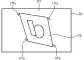
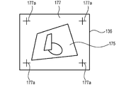
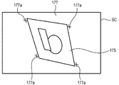
- Figs. 3A through 3C are explanatory diagrams showing an example of an action of the projector 100 correcting the distortion of the projection image, wherein Fig. 3A shows a projection example to the screen SC before the correction, Fig. 3B shows an example of the image formed in the image formable area 136, and Fig. 3C shows a projection example to the screen SC after the correction.
- the image projected on the screen SC has a keystone distortion as shown in Fig. 3A due to the installation angle of the projector 100 with respect to the screen SC.
- Fig. 3A shows an example of projecting the image obtained by superimposing the correction pattern 177 on the image 175 as shown in Fig. 2C.
- the image 175 is projected with a distortion, and the positions of the markers 177a are shifted from the rectangular arrangement in accordance with the keystone distortion.
- the keystone distortion correction section 132 deforms the image 175.
- the image output from the image processor 131 to the light modulation device drive section 134 includes the deformed image 175
- the deformed image 175 as shown in Fig. 3B is drawn in the image forming area 137 of the light modulation device 130.
- the image forming area 137 in which the image 175 is drawn is a part of the image formable area 136.
- the superimposition processing section 133 connected to the keystone distortion correction section 132 in the posterior stage thereof superimposes the correction pattern 177 on the image output by the keystone distortion correction section 132, on which the distortion correction process has been performed, the distortion correction process is not performed on the correction pattern 177. Therefore, as shown in Fig. 3B, the four markers 177a respectively disposed at the four corners of the rectangular shape are drawn in the image 175 in the same state as the state shown in Fig. 2C in which no distortion correction process has been performed. Therefore, as shown in Fig. 3C, although the image 175 is projected with a rectangular shape to the screen SC in the state in which the keystone distortion is corrected, the correction pattern 177 remains to keep the state of the keystone distortion. In other words, the positions of the markers 177a are shifted from the positions without the keystone distortion.
- the correction control section 122 When correcting the keystone distortion, the correction control section 122 makes the imaging section 180 shoot the screen SC, detects the positions of the markers 177a from the shot image, and then performs the calculation by the zoom ratio calculation section 123, the focal distance calculation section 124, the 3D measurement section 125, and the projection angle calculation section 126 based on the positions. Then, the correction control section 122 calculates the parameters for the distortion correction based on these calculation results, and then sets the parameters thus calculated to the keystone distortion correction section 132. In the series of processes, the correction control section 122 compares the positions of the markers 177a detected in the shot-image data of the imaging section 180 with the positions of the markers 177a in the data of the correction pattern 177 stored in the correction pattern storage section 172.
- the screen SC is newly shot by the imaging section 180, then the markers 177a are detected from the new shot-image data, and then the parameters are calculated.
- the markers 177a are moved by the distortion correction process. Therefore, the positions of the markers 177a on the screen SC are determined by a process performed by the keystone distortion correction section 132 in addition to the installation angle and the distance between the screen SC and the projector 100. Therefore, if the markers 177a moved by the keystone distortion correction section 132 are shot, and the positions of the markers 177a in the shot-image data are compared with the positions of the markers 177a in the correction pattern 177 stored in the correction pattern storage section 172, it is not achievable to correctly obtain the installation angle and the distance between the screen SC and the projector 100. In this case, in order to correctly obtain the installation angle and the distance, it is necessary to perform a process of eliminating the influence of the distortion correction process having been previously performed.
- the projector 100 determines that the start condition of the distortion correction process is satisfied, the projector 100 performs the distortion correction process before the projector 100 stops, and thereafter, repeatedly performs the distortion correction process with a predetermined period until the condition for completing the distortion correction process is satisfied.
- the distortion correction process is periodically (every time a predetermined period elapses) performed, and the image on which the correction is performed is periodically projected on the screen SC, the user can see the state of the correction even before the projector stops or the operation for completing the distortion correction is performed.
- the distortion correction process is performed in the state in which the projector 100 stops after the movement of the projector 100 has stopped and before the standby period elapses, the image corrected in accordance with the position where the projector 100 stops is projected on the screen SC.
- the image with the correction completed can be projected before the standby period substantially elapses, and the image without the distortion can promptly be projected.
- the period with which the projector 100 repeatedly performs the distortion correction process is shorter than the standby period described above.
- the distortion correction process is also applied to the correction pattern 177, there arises the necessity of performing the calculation for eliminating the influence of the distortion correction a plurality of times with respect to the positions of the markers 177a, and the load of the process for calculating the parameters increases. Therefore, if it is arranged that the distortion correction process is not performed on the correction pattern 177 as in the present embodiment, the positions of the markers 177a always correspond to the positions shifted as much as the value reflecting the installation angle and the distance between the screen SC and the projector 100.
- the superimposition processing section 133 for performing the process of superimposing the correction pattern 177 on the image to be projected by the projection section 101 is connected to the keystone distortion correction section 132 for performing the distortion correction process in the posterior stage thereof, and the image on which the superimposition processing section 133 performs the superimposition process is output to the light modulation device drive section 134, and is then drawn in the light modulation device 130. Therefore, since the procedure of the process in the projector 100 is arranged to be the procedure with which the correction pattern 177 is not affected by the distortion correction process, it is possible to arrange that the correction pattern 177 is not deformed by the distortion correction process without performing a special process.
- Fig. 4 is a flowchart showing the action of the projector 100.
- the CPU 120 of the projector 100 controls the light source drive section 141 to put the light source 140 on (step S11). Further, the CPU 120 controls the lens drive section 154 to perform the optical adjustment in the projection optical system 150, and at the same time, makes the image processor 131 perform adjustment of the brightness of the image, adjustment corresponding to the designated color mode, and so on (step S12).
- the projection control section 121 provided to the CPU 120 projects (step S13) the image output from the A/D conversion section 110. After starting the projection, the projection control section 121 determines (step S14) whether or not the start condition of the distortion correction process is satisfied.
- the start condition is either of the fact that the start instruction operation by the remote controller 191 or the operation section 195 is performed and the fact that the detection value of the motion detection section 185 exceeds the threshold value. If the start condition of the distortion correction process is satisfied (YES in the step S14), the projection control section 121 reads out the correction pattern stored in the correction pattern storage section 172, then makes the superimposition processing section 133 superimpose the image, and then makes the correction pattern be projected on the screen SC (step S15).
- the correction control section 122 makes the imaging section 180 shoot the screen SC, and then obtains the shot-image data from the shot-image memory 182 (step S16).
- the correction control section 122 detects the markers of the correction pattern in the shot-image data, and performs the calculation by the zoom ratio calculation section 123, the focal distance calculation section 124, the 3D measurement section 125, and the projection angle calculation section 126 to thereby calculate the parameters for correcting the keystone distortion caused in the image on the screen SC (step S17).
- the correction control section 122 updates (step S18) the parameters set to the keystone distortion correction section 132 with the new parameters, and then makes the keystone distortion correction section 132 perform the distortion correction process on the image presently projected.
- the correction control section 122 controls the lens drive section 154 based on the value calculated from the positions of the markers to perform the focus adjustment (step S19). Subsequently, the distortion correction process based on the new parameters is performed by the keystone distortion correction section 132, and the image obtained by the superimposition processing section 133 superimposing the correction pattern on the image having been processed is projected on the screen SC (step S20).
- the projection control section 121 determines (step S21) whether or not the condition for completing the distortion correction process is satisfied.
- the condition for completing the distortion correction process is either of the fact that the instruction operation for completing the distortion correction process is performed by the remote controller 191 or the operation section 195 and the fact that the standby period elapses after the detection value of the motion detection section 185 has reached a value equal to or lower than the threshold value. If either of the conditions has not yet been satisfied (NO in the step S21), the process returns to the step S16.
- the projector 100 performs the distortion correction process in real time during the period from when the start condition of the distortion correction process has been satisfied to when the condition for completing it is satisfied.
- the distortion correction process is performed a plurality of times (i.e., two or more times) during the period from when the start condition of the distortion correction process has satisfied to when the condition for completing the distortion correction process is satisfied.
- a plurality of distortion correction processes are continuously performed during the period from when the start condition of the distortion correction process has satisfied to when the condition for completing the distortion correction process is satisfied.
- the projection control section 121 makes the superimposition processing section 133 terminate (step S22) the process of superimposing the correction pattern, and then the projection control section 121 determines (step S23) whether or not the projector 100 terminates the projection, and if it does not terminate the projection (NO in the step S23), the process returns to the step S14. Further, if the projector 100 terminates the projection in accordance with the operation of the remote controller 191 or the operation section 195 (YES in the step S23), the projection control section 121 terminates the action related to the image projection by the projection section 101, and puts the light source 140 off (step S24).
- the process proceeds to the step S23 to determine whether or not the projection is terminated. It should be noted that if the projection is not terminated in the step S23, the process returns to the step S14 to repeatedly determine whether or not the start condition is satisfied, and the period of the determination in the step S14 is set in advance. In other words, during the period in which the start condition is not satisfied and the projection is not terminated, the determination is repeatedly performed with the set period.
- the distortion correction is performed based on the state of the correction pattern projected on the screen SC, the correction pattern is projected until the distortion correction process is completed without reflecting the distortion correction process on the correction pattern.
- the distortion correction can be performed without adding the correction having already been performed. Therefore, it is possible to perform the process of correcting the distortion of the projection image on the screen SC a plurality of times, and at the same time reduce the load of the arithmetic processing related to the correction.
- the projection control section 121 provided to the CPU 120 makes the correction pattern be projected in the state in which the result of the distortion correction process is not reflected, while updating the projection state of the image presently projected so as to reflect the result of the distortion correction process. Therefore, it is possible to inform the user of the change in the image due to the distortion correction process in real time without waiting for the completion of the series of distortion correction processes. Further, the projection control section 121 determines that the start condition of the distortion correction process is satisfied based on the motion of the projector 100 detected by the motion detection section 185 or the operation of the remote controller 191 or the operation section 195.
- the distortion correction process it is possible to promptly start the distortion correction process, and perform, for example, the distortion correction process a plurality of times while reducing the load of the processing. Further, since the projection control section 121 determines that the condition for completing the distortion correction process is satisfied based on the motion of the projector 100 or the external operation, it is possible to continuously perform the distortion correction process during the period before the condition is satisfied to thereby surely and accurately correct the distortion of the projection image. Further, since the distortion correction process is performed a plurality of times and the corrected image is projected on the screen SC without waiting for the completion of the distortion correction process, there is no chance of waiting the user viewing the distorted image. Therefore, since the convenience is not degraded even if the condition for completing the distortion correction process is set to be strict, by setting the condition so that the distortion correction process is completed when the projector 100 more surely stops, the keystone distortion can more surely be corrected.
- the projector 100 has the configuration in which the image is corrected by the keystone distortion correction section 132 and the image thus corrected is projected on the screen SC before the condition for completing the distortion correction process is satisfied, and if the distortion correction is performed a plurality of times, the image projected on the screen SC is updated every time the distortion correction process is performed. According to this configuration, if the projector 100 is moved violently, the change in the image becomes rapid. Therefore, it is also possible to perform a process of suppressing a steep change in the image before the condition for completing the distortion correction process is satisfied.
- the projection control section 121 makes the projection state of the image presently projected be updated so as to be in a middle state between the state after reflecting the distortion correction process and the state before reflecting the distortion correction process. Specifically, every time the distortion correction process is performed, it is also possible to generate the middle image between the image corrected with the parameters calculated by the correction control section 122 in the distortion correction process and the image having been projected before the distortion correction process, and then draw the middle image in the light modulation device 130 to thereby project it on the screen SC.
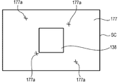
- FIG. 5A shows a projection example to the screen SC before the correction
- Fig. 5B shows an example of the image formed in the image formable area 136 of the light modulation device 130
- Fig. 5C shows a projection example to the screen SC after the correction.
- the correction control section 122 makes the imaging section 180 perform shooting, and then calculates the parameters for correction based on the positions of the markers 177a in the shot-image data.
- the keystone distortion correction section 132 performs the process of deforming the shape of the image forming area 137 for drawing the image 175, namely the corrected outline of the image 175, based on the parameters calculated by the correction control section 122, the process is not performed inside the image 175, and the inside of the image 175 is assumed to be blank.
- the outline 138 representing the contour of the image 175 corrected by the distortion correction process is drawn in the image formable area 136 of the light modulation device 130 as shown in Fig. 5B, the image 175 is not drawn. Further, the correction pattern 177 on which the distortion correction process is not performed is drawn so as to be superimposed on the outline 138. If the projection on the screen SC is performed in this state, the outline 138 corrected is imaged on the screen SC as a rectangular shape as shown in Fig. 5C. Further, the correction pattern 177 is projected having the shape without the correction.
- Fig. 6 is a flowchart showing an action of the projector 100 according to the second embodiment.
- the same processes as those explained with reference to Fig. 4 are denoted with the same step numbers.
- the keystone distortion correction section 132 performs the process of deforming the shape of the image 175 in accordance with the parameters thus updated, then determines the outer shape, and then generates the image of the outline (step S31).
- the outline generated by the keystone distortion correction section 132 is drawn in the light modulation device 130, and is then projected on the screen SC (step S32).
- the keystone distortion correction section 132 is not required to perform the conversion process on all of the pixels constituting the image 175, the load of the distortion correction process can significantly be reduced. Therefore, it is possible to repeatedly perform the distortion correction process with a short period and update the image to be projected on the screen SC during the period, for example, from when the start condition of the distortion correction process is satisfied in the step S14 to when the completion condition is satisfied in the step S21. Further, since it is possible for the user to know whether or not the state of the keystone distortion correction is preferable if the outline 138 is projected on the screen SC, sufficient information can be provided to the user only with the outline 138.
- the projection control section 121 determines in the step S21 that the completion condition of the distortion correction process is satisfied, terminates the projection of the correction pattern 177 in the step S22, then makes the keystone distortion correction section 132 perform the process of deforming the whole of the image 175 in accordance with the parameters thus set, and then projects the whole of the image 175 thus corrected on the screen SC (step S33).
- the projection of the outline 138 having been projected on the screen SC is terminated, and the image 175 is projected in the corrected state. In other words, the transition to the normal projection state is promptly made after the completion of the distortion correction.
- the correction pattern 177 is projected in the state of not reflecting the result of the distortion correction process, and at the same time, the outline 138 representing the shape of the image 175 on which the distortion correction process has been performed is projected.
- the distortion correction process it is possible to inform the user of the change in the image by the distortion correction process without waiting for the completion of the series of the distortion correction processes, and at the same time, reduce the load related to the distortion correction process.
- each of the embodiments described above is nothing more than an example of a specific aspect to which the invention is applied, and therefore, does not limit the invention. Therefore, it is also possible to apply the invention as an aspect different from the embodiments described above.
- the explanation is presented citing the case of projecting the image input to the A/D conversion section 110 via the cable 200 as an example, the invention is not limited thereto, but can obviously be applied to the case of projecting the image or the video stored in the image storage section 171.
- the setting values related to the time, the threshold value, and so on for defining the actions of the respective sections of the projector 100 are previously stored in the ROM 170, it is also possible to adopt the configuration in which these setting values are stored in a storage medium or a device outside the projector 100, and then obtained by the projector 100 as the need arises, or the configuration in which the setting values are input in each case by the operation of the remote controller 191 or the operation section 195.
- the process of correcting the keystone distortion generated in the image on the screen SC is explained, the invention is not limited thereto, but can be applied to the process of, for example, correcting a distortion called a barrel distortion or a pin-cushion distortion.
- the imaging section 180 has the configuration including the CCD camera 181 provided with the CCD image sensors
- the invention is not limited thereto, but CMOS sensors can also be used as the image sensors of the imaging section 180.
- the invention is not limited thereto, but can be configured using a system including one liquid crystal panel and a color wheel combined with each other, a system using three digital mirror devices (DMD) for modulating the colored lights of the respective colors of RGB, a system using one digital mirror device and a color wheel combined with each other, and so on.
- DMD digital mirror devices
- the member corresponding to the combining optical system such as the cross dichroic prism is not necessary.
- each of the functional sections shown in Fig. 1 is for showing the functional configuration of the projector 100, and the specific mounting forms are not particularly limited. In other words, it is not necessarily required to install the hardware corresponding individually to each of the functional sections, but it is obviously possible to adopt the configuration of realizing the functions of the plurality of functional sections by one processor executing the program. Further, a part of the function realized by software in the embodiments described above can also be realized by hardware, or a part of the function realized by hardware can also be realized by software.
Abstract
Description
An aspect of the invention is directed to a projector including a projection unit adapted to project an image on a projection surface, a controller adapted to make the projection unit project a correcting image so as to be superimposed on the image presently projected if a start condition of a distortion correction process adapted to correct a distortion of the image projected by the projection unit is satisfied, and a correction unit adapted to perform the distortion correction process based on a state of the correcting image projected by the projection unit, and the controller makes the projection unit project the correcting image in a state in which a result of the distortion correction process fails to be reflected during a period from when the start condition of the distortion correction process is satisfied to when a condition for completing the distortion correction process is satisfied, and a period in which the correction unit performs the distortion correction process a plurality of times.
According to this aspect of the invention, in the case of performing the distortion correction based on the state of the correcting image projected on the projection surface, the distortion correction process is not reflected on the correcting image, and the correcting image is projected until the distortion correction process is completed. Therefore, in the case of performing the distortion correction process a plurality of times, the distortion correction can be performed without adding the correction having already been performed. Thus, the process of correcting the distortion of the projection image on a projection surface can be performed a plurality of times, and at the same time, a load of arithmetic processing related to the correction can be reduced.
According to this aspect of the invention, since the result of the process is reflected on the projection state of the image every time the distortion correction process is performed in the case in which the distortion correction process is performed a plurality of times, it is possible to inform the user of the change in the image by the distortion correction process in real time without waiting for the completion of the series of distortion correction processes.
According to this aspect of the invention, the result of the process is reflected on the projection state of the image every time the distortion correction process is performed, and at the same time, the level of the change in the image can be reduced. Thus, in the case in which the distortion correction process is performed a plurality of times, it is possible to inform the user of the change in the image due to the distortion correction process in real time, and at the same time, the level of the change in the image is reduced to thereby prevent the uncomfortable feeling of the user.
According to this aspect of the invention, since the shape of the image reflecting the result of the process is shown every time the distortion correction process is performed in the case in which the distortion correction process is performed a plurality of times, it is possible to inform the user of the change in the image by the distortion correction process without waiting for the completion of the series of distortion correction processes. Further, since the process of obtaining the shape of the image reflecting the result of the distortion correction process has the load smaller than that of the process of deforming the image, the load of the distortion correction process can be reduced.
According to this aspect of the invention, it is possible to promptly start the distortion correction process, and for example, perform the distortion correction process a plurality of times with a reduced processing load.
According to this aspect of the invention, by continuously performing the distortion correction process until the condition is satisfied, the distortion of the projection image can surely and accurately be corrected.
According to this aspect of the invention, in the case of performing the distortion correction based on the state of the correcting image projected on the projection surface, the distortion correction process is not reflected on the correcting image, and the correcting image is projected until the distortion correction process is completed. Therefore, in the case of performing the distortion correction process a plurality of times, the distortion correction can be performed without adding the correction having already been performed. Thus, the process of correcting the distortion of the projection image on a projection surface can be performed a plurality of times, and at the same time, a load of arithmetic processing related to the correction can be reduced.
An embodiment to which the invention is applied will hereinafter be explained with reference to the accompanying drawings.
Fig. 1 is a block diagram showing an overall configuration of a
The image data input to the
The
The
It should be noted that it is also possible to adopt the configuration in which the
The
The
Further, the
Then, the
Further, the
The keystone
The
Figs. 2A through 2C are explanatory diagrams showing an action of the
If the
The image projected on the screen SC has a keystone distortion as shown in Fig. 3A due to the installation angle of the
Here, when the distortion correction process by the
Therefore, as shown in Fig. 3C, although the
Therefore, in the case of further performing the distortion correction process after the distortion correction process has been performed as shown in Fig. 3C, the screen SC is newly shot by the
Further, in the present embodiment, the
When the power of the
After starting the projection, the
Further, the
Further, since the
A second embodiment to which the invention is applied will hereinafter be explained. In the second embodiment, there is explained a configuration of projecting the outline representing the shape of the image after the distortion correction process on the screen SC instead of the image on which the distortion correction process is performed during the period in which the distortion correction process is repeatedly performed. It should be noted that in the second embodiment, the sections of the
Figs. 5A through 5C are explanatory diagrams showing an example of the action of the
If the projection on the screen SC is performed in this state, the
In the action shown in Fig. 6, in the
Thus, since the keystone
Further, although in each of the embodiments described above, the process of correcting the keystone distortion generated in the image on the screen SC is explained, the invention is not limited thereto, but can be applied to the process of, for example, correcting a distortion called a barrel distortion or a pin-cushion distortion.
Further, each of the functional sections shown in Fig. 1 is for showing the functional configuration of the
101 projection section (projection unit)
120 CPU (controller)
121 projection control section
122 correction control section (correction unit)
130 light modulation device
131 image processor
132 keystone distortion correction section (correction unit)
133 superimposition processing section
134 light modulation device drive section
170 ROM
172 correction pattern storage section
177 correction pattern (correcting image)
180 imaging section
185 motion detection section
191 remote controller
195 operation section
SC screen (projection surface)
Claims (7)
- A projector comprising:
a projection unit adapted to project an image on a projection surface;
a controller adapted to make the projection unit project a correcting image so as to be superimposed on the image presently projected if a start condition of a distortion correction process adapted to correct a distortion of the image projected by the projection unit is satisfied; and
a correction unit adapted to perform the distortion correction process based on a state of the correcting image projected by the projection unit,
wherein the controller makes the projection unit project the correcting image in a state in which a result of the distortion correction process fails to be reflected during a period from when the start condition of the distortion correction process is satisfied to when a condition for completing the distortion correction process is satisfied, and a period in which the correction unit performs the distortion correction process a plurality of times. - The projector according to Claim 1, wherein
the controller makes the projection unit project the correcting image in the state in which the result of the distortion correction process fails to be reflected, and makes the projection unit update the projection state of the image presently projected so as to reflect the result of the distortion correction process if the correction unit performs the distortion correction process. - The projector according to Claim 1 wherein
the controller makes the projection unit project the correcting image in the state in which the result of the distortion correction process fails to be reflected, and makes the projection unit update the projection state of the image presently projected so as to be an intermediate state between a state reflecting the distortion correction process and a state before reflecting the distortion correction process if the correction unit performs the distortion correction process. - The projector according to Claim 1, wherein
the controller makes the projection unit project the correcting image in the state in which the result of the distortion correction process fails to be reflected, and performs projection of showing a shape of the image after the distortion correction process if the correction unit performs the distortion correction process. - The projector according to any one of Claims 1 to 4, wherein
the controller determines that the start condition of the distortion correction process is satisfied based on one of a motion of the projector and an external operation. - The projector according to any one of Claims 1 to 5, wherein
the controller determines that the condition for completing the distortion correction process is satisfied based on one of a motion of the projector and an external operation. - A method of controlling a projector including a projection unit adapted to project an image on a projection surface, the method comprising:
making the projection unit project a correcting image so as to be superimposed on the image presently projected if a start condition of a distortion correction process adapted to correct a distortion of the image projected by the projection unit is satisfied;
performing the distortion correction process based on a state of the correcting image projected; and
making the projection unit project the correcting image in a state in which a result of the distortion correction process fails to be reflected during a period from when the start condition of the distortion correction process is satisfied to when a condition for completing the distortion correction process is satisfied, and a period in which the distortion correction process is performed a plurality of times.
Priority Applications (6)
| Application Number | Priority Date | Filing Date | Title |
|---|---|---|---|
| US14/374,321 US20150049117A1 (en) | 2012-02-16 | 2013-01-29 | Projector and method of controlling projector |
| KR1020147024708A KR101725512B1 (en) | 2012-02-16 | 2013-01-29 | Projector and method of controlling projector |
| BR112014020367-9A BR112014020367A2 (en) | 2012-02-16 | 2013-01-29 | projector and method for controlling prejudice |
| EP13710072.3A EP2815275A2 (en) | 2012-02-16 | 2013-01-29 | Projector and method of controlling projector |
| RU2014137247/28A RU2601242C2 (en) | 2012-02-16 | 2013-01-29 | Projector and projector control method |
| IN6747DEN2014 IN2014DN06747A (en) | 2012-02-16 | 2014-08-12 |
Applications Claiming Priority (2)
| Application Number | Priority Date | Filing Date | Title |
|---|---|---|---|
| JP2012031447A JP5924020B2 (en) | 2012-02-16 | 2012-02-16 | Projector and projector control method |
| JP2012-031447 | 2012-02-16 |
Publications (2)
| Publication Number | Publication Date |
|---|---|
| WO2013121712A2 true WO2013121712A2 (en) | 2013-08-22 |
| WO2013121712A3 WO2013121712A3 (en) | 2013-11-14 |
Family
ID=47891822
Family Applications (1)
| Application Number | Title | Priority Date | Filing Date |
|---|---|---|---|
| PCT/JP2013/000446 WO2013121712A2 (en) | 2012-02-16 | 2013-01-29 | Projector and method of controlling projector |
Country Status (10)
| Country | Link |
|---|---|
| US (1) | US20150049117A1 (en) |
| EP (1) | EP2815275A2 (en) |
| JP (1) | JP5924020B2 (en) |
| KR (1) | KR101725512B1 (en) |
| CN (1) | CN103259995B (en) |
| BR (1) | BR112014020367A2 (en) |
| IN (1) | IN2014DN06747A (en) |
| RU (1) | RU2601242C2 (en) |
| TW (1) | TWI588588B (en) |
| WO (1) | WO2013121712A2 (en) |
Cited By (1)
| Publication number | Priority date | Publication date | Assignee | Title |
|---|---|---|---|---|
| WO2019195884A1 (en) * | 2018-04-10 | 2019-10-17 | Immersaview Pty Ltd | Image calibration for projected images |
Families Citing this family (9)
| Publication number | Priority date | Publication date | Assignee | Title |
|---|---|---|---|---|
| JP2014179698A (en) * | 2013-03-13 | 2014-09-25 | Ricoh Co Ltd | Projector and control method of projector, and program of control method and recording medium with program recorded thereon |
| JP2016010025A (en) * | 2014-06-25 | 2016-01-18 | 株式会社リコー | Video projector, video projection method, and program |
| CN105812694B (en) * | 2014-12-29 | 2024-02-06 | 中强光电股份有限公司 | Projection system and projection method thereof |
| JP6598800B2 (en) * | 2015-01-06 | 2019-10-30 | マクセル株式会社 | Video display device, video display method, and video display system |
| US9992464B1 (en) * | 2016-11-11 | 2018-06-05 | Christie Digital Systems Usa, Inc. | Method and system for screen correction |
| JP6897191B2 (en) * | 2017-03-17 | 2021-06-30 | セイコーエプソン株式会社 | Projector and projector control method |
| WO2019043854A1 (en) * | 2017-08-31 | 2019-03-07 | 三菱電機株式会社 | Optical device controller, method for controlling optical device, and optical device control program |
| US11575863B2 (en) | 2021-04-08 | 2023-02-07 | Sony Group Corporation | Depth-based projection of image-based content |
| CN114268777B (en) * | 2021-12-20 | 2023-08-18 | 青岛海信激光显示股份有限公司 | Starting method of laser projection equipment and laser projection system |
Citations (1)
| Publication number | Priority date | Publication date | Assignee | Title |
|---|---|---|---|---|
| JP2010130225A (en) | 2008-11-26 | 2010-06-10 | Seiko Epson Corp | Projection display device and adjustment method for projection |
Family Cites Families (234)
| Publication number | Priority date | Publication date | Assignee | Title |
|---|---|---|---|---|
| US3837740A (en) * | 1972-01-20 | 1974-09-24 | D Johnson | Photo projection drawing board |
| US4862388A (en) * | 1986-12-15 | 1989-08-29 | General Electric Company | Dynamic comprehensive distortion correction in a real time imaging system |
| US5900982A (en) * | 1987-12-31 | 1999-05-04 | Projectavision, Inc. | High efficiency light valve projection system |
| US6392689B1 (en) * | 1991-02-21 | 2002-05-21 | Eugene Dolgoff | System for displaying moving images pseudostereoscopically |
| DE69526635T2 (en) * | 1994-12-29 | 2002-12-05 | Koninkl Philips Electronics Nv | Imaging device and method for improving geometric optical image distortions |
| JP3473335B2 (en) * | 1996-08-19 | 2003-12-02 | セイコーエプソン株式会社 | Projection display device |
| US5999194A (en) * | 1996-11-14 | 1999-12-07 | Brunelle; Theodore M. | Texture controlled and color synthesized animation process |
| DE19855885A1 (en) * | 1997-12-04 | 1999-08-05 | Fuji Photo Film Co Ltd | Image processing method for digital photographic copier providing photographic prints |
| JP4089051B2 (en) * | 1998-02-18 | 2008-05-21 | セイコーエプソン株式会社 | Image processing apparatus and image processing method |
| US6310650B1 (en) * | 1998-09-23 | 2001-10-30 | Honeywell International Inc. | Method and apparatus for calibrating a tiled display |
| AU2001275308A1 (en) * | 2000-06-06 | 2001-12-17 | Frauenhofer Institut Fuer Graphische Datenverarbeitung | The extended virtual table: an optical extension for table-like projection systems |
| US6803906B1 (en) * | 2000-07-05 | 2004-10-12 | Smart Technologies, Inc. | Passive touch system and method of detecting user input |
| US7313289B2 (en) * | 2000-08-30 | 2007-12-25 | Ricoh Company, Ltd. | Image processing method and apparatus and computer-readable storage medium using improved distortion correction |
| JP4022374B2 (en) * | 2001-01-26 | 2007-12-19 | 株式会社ルネサステクノロジ | Semiconductor device manufacturing method and system |
| CN100465995C (en) * | 2001-06-12 | 2009-03-04 | 奥普提克斯晶硅有限公司 | System and method for correcting keystone distortion |
| JP3742027B2 (en) * | 2002-04-08 | 2006-02-01 | Necビューテクノロジー株式会社 | Projection image distortion correction method, distortion correction program, and projection-type image display device |
| JP3761491B2 (en) * | 2002-05-10 | 2006-03-29 | Necビューテクノロジー株式会社 | Projection image distortion correction method, distortion correction program, and projection-type image display device |
| JP4144292B2 (en) * | 2002-08-20 | 2008-09-03 | ソニー株式会社 | Image processing apparatus, image processing system, and image processing method |
| JP3731663B2 (en) * | 2002-12-04 | 2006-01-05 | セイコーエプソン株式会社 | Image processing system, projector, and image processing method |
| US7380946B1 (en) * | 2003-01-28 | 2008-06-03 | Pixelworks, Inc. | Semiautomatic keystone correction system and method |
| JP2004234379A (en) * | 2003-01-30 | 2004-08-19 | Sony Corp | Image processing method, image processor, and imaging device and display device to which image processing method is applied |
| JP3871061B2 (en) * | 2003-03-25 | 2007-01-24 | セイコーエプソン株式会社 | Image processing system, projector, program, information storage medium, and image processing method |
| JP3846592B2 (en) * | 2003-06-26 | 2006-11-15 | セイコーエプソン株式会社 | Image processing system, projector, program, information storage medium, and image processing method |
| JP3630166B2 (en) * | 2003-06-26 | 2005-03-16 | セイコーエプソン株式会社 | Adjusting the amount of distortion correction in the projected image |
| EP1650705B1 (en) * | 2003-07-28 | 2013-05-01 | Olympus Corporation | Image processing apparatus, image processing method, and distortion correcting method |
| JP3827662B2 (en) * | 2003-09-10 | 2006-09-27 | Necビューテクノロジー株式会社 | Projection display |
| JP4363151B2 (en) * | 2003-10-14 | 2009-11-11 | カシオ計算機株式会社 | Imaging apparatus, image processing method thereof, and program |
| JP4345745B2 (en) * | 2003-10-15 | 2009-10-14 | セイコーエプソン株式会社 | Multi-projection display |
| US7410263B2 (en) * | 2003-11-06 | 2008-08-12 | Seiko Epson Corporation | Rear projection type multi-projection display |
| US7338175B2 (en) * | 2003-12-01 | 2008-03-04 | Seiko Epson Corporation | Front projection type multi-projection display |
| JP4042695B2 (en) * | 2004-01-08 | 2008-02-06 | セイコーエプソン株式会社 | Projector and zoom adjustment method |
| JP2005223393A (en) * | 2004-02-03 | 2005-08-18 | Casio Comput Co Ltd | Projector, projecting method, and projection program |
| JP3880582B2 (en) * | 2004-02-13 | 2007-02-14 | Necビューテクノロジー株式会社 | Projector with multiple cameras |
| JP2005267457A (en) * | 2004-03-19 | 2005-09-29 | Casio Comput Co Ltd | Image processing device, imaging apparatus, image processing method and program |
| JP4006601B2 (en) * | 2004-03-29 | 2007-11-14 | セイコーエプソン株式会社 | Image processing system, projector, program, information storage medium, and image processing method |
| US7144115B2 (en) * | 2004-04-14 | 2006-12-05 | Sharp Laboratories Of America, Inc. | Projection system |
| US6997563B1 (en) * | 2004-05-19 | 2006-02-14 | Pixelworks, Inc. | Keystone correction derived from the parameters of projectors |
| JP2006006912A (en) * | 2004-05-27 | 2006-01-12 | Aruze Corp | Game machine |
| JP3960390B2 (en) * | 2004-05-31 | 2007-08-15 | Necディスプレイソリューションズ株式会社 | Projector with trapezoidal distortion correction device |
| JP4148241B2 (en) * | 2004-06-03 | 2008-09-10 | セイコーエプソン株式会社 | projector |
| JP3722146B1 (en) * | 2004-06-16 | 2005-11-30 | セイコーエプソン株式会社 | Projector and image correction method |
| US7629995B2 (en) * | 2004-08-06 | 2009-12-08 | Sony Corporation | System and method for correlating camera views |
| US8066384B2 (en) * | 2004-08-18 | 2011-11-29 | Klip Collective, Inc. | Image projection kit and method and system of distributing image content for use with the same |
| JP2006074512A (en) * | 2004-09-02 | 2006-03-16 | Casio Comput Co Ltd | Photographing device, and image processing method, and program for photographing device |
| CN100527805C (en) * | 2004-09-15 | 2009-08-12 | 三菱电机株式会社 | Image projection system and image geometry corrector |
| JP4655565B2 (en) * | 2004-09-21 | 2011-03-23 | 株式会社ニコン | Projector device, mobile phone, camera |
| US20120182403A1 (en) * | 2004-09-30 | 2012-07-19 | Eric Belk Lange | Stereoscopic imaging |
| EP1821183A4 (en) * | 2004-10-05 | 2011-01-26 | Nikon Corp | Electronic device |
| JP4380557B2 (en) * | 2005-02-15 | 2009-12-09 | カシオ計算機株式会社 | Projector, chart image display method and program |
| US20060204125A1 (en) * | 2005-03-09 | 2006-09-14 | Kempf Jeffrey M | Multi-dimensional keystone correction image projection system and method |
| CN101213487B (en) * | 2005-06-30 | 2010-06-16 | 株式会社理光 | Projection image display device |
| US9285897B2 (en) * | 2005-07-13 | 2016-03-15 | Ultimate Pointer, L.L.C. | Easily deployable interactive direct-pointing system and calibration method therefor |
| JP4114683B2 (en) * | 2005-08-01 | 2008-07-09 | セイコーエプソン株式会社 | How to adjust the position of the projected image |
| JP2007049266A (en) * | 2005-08-08 | 2007-02-22 | Olympus Corp | Picture imaging apparatus |
| US7551179B2 (en) * | 2005-08-10 | 2009-06-23 | Seiko Epson Corporation | Image display apparatus and image adjusting method |
| US7792389B2 (en) * | 2005-08-10 | 2010-09-07 | Seiko Epson Corporation | Image processing content determining apparatus, computer readable medium storing thereon image processing content determining program and image processing content determining method |
| DE602006021219D1 (en) * | 2005-11-11 | 2011-05-19 | Sony Corp | PICTURE PROCESSING DEVICE, PICTURE PROCESSING METHOD, PROGRAM THEREFOR, THE RECORDING MEDIUM AND PICTURE DEVICE CONTAINING THE PROGRAM |
| US8777418B2 (en) * | 2006-01-26 | 2014-07-15 | Christie Digital Systems Usa, Inc. | Calibration of a super-resolution display |
| US7330604B2 (en) * | 2006-03-02 | 2008-02-12 | Compulink Management Center, Inc. | Model-based dewarping method and apparatus |
| JP4104631B2 (en) * | 2006-03-27 | 2008-06-18 | 三洋電機株式会社 | Driving support device |
| US20070291184A1 (en) * | 2006-06-16 | 2007-12-20 | Michael Harville | System and method for displaying images |
| US7854518B2 (en) * | 2006-06-16 | 2010-12-21 | Hewlett-Packard Development Company, L.P. | Mesh for rendering an image frame |
| JP2008026879A (en) * | 2006-06-19 | 2008-02-07 | Seiko Epson Corp | Display system and method |
| JP4816569B2 (en) * | 2006-07-06 | 2011-11-16 | セイコーエプソン株式会社 | Image display system |
| JP4816563B2 (en) * | 2006-07-06 | 2011-11-16 | セイコーエプソン株式会社 | Image display system |
| US20080007700A1 (en) * | 2006-07-10 | 2008-01-10 | Vanbaar Jeroen | Method and system for aligning an array of rear-projectors |
| US8406562B2 (en) * | 2006-08-11 | 2013-03-26 | Geo Semiconductor Inc. | System and method for automated calibration and correction of display geometry and color |
| JP4238901B2 (en) * | 2006-08-17 | 2009-03-18 | セイコーエプソン株式会社 | Projection system, information processing apparatus, information processing program, recording medium thereof, projector, program thereof, and recording medium thereof |
| JP4258540B2 (en) * | 2006-09-01 | 2009-04-30 | セイコーエプソン株式会社 | Information processing apparatus, information processing program, and recording medium thereof |
| JP4470930B2 (en) * | 2006-09-21 | 2010-06-02 | ソニー株式会社 | Image processing apparatus, image processing method, and program |
| US7690795B2 (en) * | 2006-10-06 | 2010-04-06 | Hewlett-Packard Development Company, L.P. | Projector/camera system |
| JP4977556B2 (en) * | 2006-10-11 | 2012-07-18 | ルネサスエレクトロニクス株式会社 | Semiconductor integrated circuit device and drawing processing display system |
| JP2008146155A (en) * | 2006-12-06 | 2008-06-26 | Sony Corp | Image processing method and device |
| WO2008081575A1 (en) * | 2006-12-27 | 2008-07-10 | Nikon Corporation | Distortion correcting method, distortion correcting device, distortion correcting program, and digital camera |
| US8994757B2 (en) * | 2007-03-15 | 2015-03-31 | Scalable Display Technologies, Inc. | System and method for providing improved display quality by display adjustment and image processing using optical feedback |
| JP5069038B2 (en) * | 2007-04-20 | 2012-11-07 | 三菱電機株式会社 | Rear projection display |
| WO2008139577A1 (en) * | 2007-05-09 | 2008-11-20 | Fujitsu Microelectronics Limited | Image processor, imager, and image distortion correcting method |
| WO2009000906A1 (en) * | 2007-06-26 | 2008-12-31 | Dublin City University | A method for high precision lens distortion calibration and removal |
| JP5088018B2 (en) * | 2007-06-28 | 2012-12-05 | 富士ゼロックス株式会社 | Image processing apparatus and control program |
| US8218003B2 (en) * | 2007-10-05 | 2012-07-10 | Seiko Epson Corporation | Optimization strategies for GPU view projection matrix implementation |
| EP2208354A4 (en) * | 2007-10-10 | 2010-12-22 | Gerard Dirk Smits | Image projector with reflected light tracking |
| JP2009139246A (en) * | 2007-12-07 | 2009-06-25 | Honda Motor Co Ltd | Device, method and program for processing image, position detecting device and moving body equipped with this |
| US8807762B2 (en) * | 2008-01-11 | 2014-08-19 | Nikon Corporation | Projector |
| US20100253861A1 (en) * | 2008-01-15 | 2010-10-07 | Yoshihiro Tomaru | Display |
| US20090195758A1 (en) * | 2008-01-31 | 2009-08-06 | Hewlett-Packard Development Company, L.P. | Meshes for separately mapping color bands |
| JP2009200557A (en) * | 2008-02-19 | 2009-09-03 | Seiko Epson Corp | Projector, electronic apparatus, and method of controlling projector |
| JP2009216815A (en) * | 2008-03-07 | 2009-09-24 | Sanyo Electric Co Ltd | Projection type video display device |
| DE102009013169B4 (en) * | 2008-03-28 | 2021-12-09 | Heidelberger Druckmaschinen Ag | Geometry error correction while preserving specified information |
| JP4725595B2 (en) * | 2008-04-24 | 2011-07-13 | ソニー株式会社 | Video processing apparatus, video processing method, program, and recording medium |
| JP5405047B2 (en) * | 2008-05-09 | 2014-02-05 | 三洋電機株式会社 | Projection display device |
| CN101755300B (en) * | 2008-05-21 | 2014-02-05 | 松下电器产业株式会社 | Projector |
| EP2285109B1 (en) * | 2008-05-29 | 2018-11-28 | Fujitsu Limited | Vehicle image processor, and vehicle image processing system |
| US8396322B1 (en) * | 2008-06-11 | 2013-03-12 | Pixelworks, Inc. | Optical distortion correction in digital video processing applications |
| JP2010010926A (en) * | 2008-06-25 | 2010-01-14 | Toshiba Corp | Video projector, and method for controlling the same |
| JP5310266B2 (en) * | 2009-05-29 | 2013-10-09 | セイコーエプソン株式会社 | Projector and control method thereof |
| JP5481833B2 (en) * | 2008-10-29 | 2014-04-23 | セイコーエプソン株式会社 | Projector and projector control method |
| US8297757B2 (en) * | 2008-10-29 | 2012-10-30 | Seiko Epson Corporation | Projector and projector control method |
| US8830268B2 (en) * | 2008-11-07 | 2014-09-09 | Barco Nv | Non-linear image mapping using a plurality of non-linear image mappers of lesser resolution |
| JP5401940B2 (en) * | 2008-11-17 | 2014-01-29 | セイコーエプソン株式会社 | Projection optical system zoom ratio measurement method, projection image correction method using the zoom ratio measurement method, and projector for executing the correction method |
| JP5493340B2 (en) * | 2008-11-26 | 2014-05-14 | セイコーエプソン株式会社 | Projection display apparatus and arrangement relation detection method |
| JP2010130385A (en) * | 2008-11-28 | 2010-06-10 | Sharp Corp | Image display method and image display device |
| JP5153593B2 (en) * | 2008-12-02 | 2013-02-27 | 株式会社Pfu | Image processing apparatus and image processing method |
| GB2466023A (en) * | 2008-12-08 | 2010-06-09 | Light Blue Optics Ltd | Holographic Image Projection Systems |
| US8013904B2 (en) * | 2008-12-09 | 2011-09-06 | Seiko Epson Corporation | View projection matrix based high performance low latency display pipeline |
| GB2466497B (en) * | 2008-12-24 | 2011-09-14 | Light Blue Optics Ltd | Touch sensitive holographic displays |
| JP5495572B2 (en) * | 2009-01-07 | 2014-05-21 | キヤノン株式会社 | Projector system and video conferencing system including the same |
| JP5354168B2 (en) * | 2009-01-13 | 2013-11-27 | セイコーエプソン株式会社 | Projector and control method |
| JP5262743B2 (en) * | 2009-01-20 | 2013-08-14 | セイコーエプソン株式会社 | Projection display apparatus, control method therefor, and control program therefor |
| JP5049300B2 (en) * | 2009-01-20 | 2012-10-17 | クラリオン株式会社 | Obstacle detection display |
| US8393740B2 (en) * | 2009-03-12 | 2013-03-12 | Canon Kabushiki Kaisha | Image projection system with keystone correction |
| US20100277576A1 (en) * | 2009-04-29 | 2010-11-04 | David Fattal | Systems for Capturing Images Through a Display |
| US8328365B2 (en) * | 2009-04-30 | 2012-12-11 | Hewlett-Packard Development Company, L.P. | Mesh for mapping domains based on regularized fiducial marks |
| JP5428600B2 (en) * | 2009-07-09 | 2014-02-26 | セイコーエプソン株式会社 | Projector, image projection system, and image projection method |
| US8045006B2 (en) * | 2009-07-10 | 2011-10-25 | Seiko Epson Corporation | Method and apparatus for determining the best blending of overlapped portions of projected images |
| US8102332B2 (en) * | 2009-07-21 | 2012-01-24 | Seiko Epson Corporation | Intensity scaling for multi-projector displays |
| JP2011033857A (en) * | 2009-08-03 | 2011-02-17 | Seiko Epson Corp | Projector and method of controlling the same |
| JP5327468B2 (en) * | 2009-08-04 | 2013-10-30 | セイコーエプソン株式会社 | Projector, program, information storage medium, and trapezoidal distortion correction method |
| US9274699B2 (en) * | 2009-09-03 | 2016-03-01 | Obscura Digital | User interface for a large scale multi-user, multi-touch system |
| US20110055703A1 (en) * | 2009-09-03 | 2011-03-03 | Niklas Lundback | Spatial Apportioning of Audio in a Large Scale Multi-User, Multi-Touch System |
| US20110050640A1 (en) * | 2009-09-03 | 2011-03-03 | Niklas Lundback | Calibration for a Large Scale Multi-User, Multi-Touch System |
| US8730183B2 (en) * | 2009-09-03 | 2014-05-20 | Obscura Digital | Large scale multi-user, multi-touch system |
| JP2011066738A (en) * | 2009-09-18 | 2011-03-31 | Sanyo Electric Co Ltd | Projection type video display device |
| JP5353596B2 (en) * | 2009-09-18 | 2013-11-27 | セイコーエプソン株式会社 | Projection display device and keystone correction method |
| DE102009046114B4 (en) * | 2009-10-28 | 2011-09-01 | Fraunhofer-Gesellschaft zur Förderung der angewandten Forschung e.V. | Method and apparatus for generating a calibrated projection |
| JP5442393B2 (en) * | 2009-10-29 | 2014-03-12 | 日立コンシューマエレクトロニクス株式会社 | Display device |
| JP5377278B2 (en) * | 2009-12-28 | 2013-12-25 | キヤノン株式会社 | Projection type display device and geometric distortion correction method |
| JP2011154345A (en) * | 2009-12-28 | 2011-08-11 | Sanyo Electric Co Ltd | Projection video display apparatus and image adjustment method |
| JP5359900B2 (en) * | 2010-01-26 | 2013-12-04 | セイコーエプソン株式会社 | projector |
| JP2011197635A (en) * | 2010-02-25 | 2011-10-06 | Sharp Corp | Video-image displaying screen, video-image displaying system, and method for detecting secret-filming camera |
| JP5440250B2 (en) * | 2010-02-26 | 2014-03-12 | セイコーエプソン株式会社 | Correction information calculation apparatus, image processing apparatus, image display system, and image correction method |
| JP5338718B2 (en) * | 2010-02-26 | 2013-11-13 | セイコーエプソン株式会社 | Correction information calculation apparatus, image processing apparatus, image display system, and image correction method |
| US8212945B2 (en) * | 2010-04-01 | 2012-07-03 | Seiko Epson Corporation | Method and apparatus for calibrating a projector for image warping |
| JP5471830B2 (en) * | 2010-05-25 | 2014-04-16 | セイコーエプソン株式会社 | Light modulation device position adjustment method, light modulation device position adjustment amount calculation device, and projector |
| JP5625490B2 (en) * | 2010-05-25 | 2014-11-19 | セイコーエプソン株式会社 | Projector, projection state adjustment method, and projection state adjustment program |
| JP5477185B2 (en) * | 2010-06-17 | 2014-04-23 | セイコーエプソン株式会社 | Multi-projection system, projector, and image projection control method |
| JP5839785B2 (en) * | 2010-07-06 | 2016-01-06 | キヤノン株式会社 | Projection system, projection apparatus, and imaging apparatus |
| JP5735227B2 (en) * | 2010-07-16 | 2015-06-17 | ルネサスエレクトロニクス株式会社 | Image conversion apparatus and image conversion system |
| JP5796286B2 (en) * | 2010-09-15 | 2015-10-21 | セイコーエプソン株式会社 | Projector and projector control method |
| JP5671901B2 (en) * | 2010-09-15 | 2015-02-18 | セイコーエプソン株式会社 | Projection type display device and control method thereof |
| JP2012078658A (en) * | 2010-10-04 | 2012-04-19 | Sanyo Electric Co Ltd | Projection type video display device |
| US8727539B2 (en) * | 2010-10-28 | 2014-05-20 | Seiko Epson Corporation | Projector and method of controlling projector |
| JP5397360B2 (en) * | 2010-11-12 | 2014-01-22 | カシオ計算機株式会社 | Projection device |
| JP5803184B2 (en) * | 2010-11-19 | 2015-11-04 | 株式会社リコー | Image projection apparatus and memory access method |
| JP2012118289A (en) * | 2010-11-30 | 2012-06-21 | Sanyo Electric Co Ltd | Projection type image display device |
| JP4772917B1 (en) * | 2010-12-02 | 2011-09-14 | パナソニック株式会社 | Portable information processing device |
| JP5522018B2 (en) * | 2010-12-15 | 2014-06-18 | 富士通株式会社 | Image processing apparatus, image processing method, and image processing program |
| KR101172629B1 (en) * | 2011-01-04 | 2012-08-08 | 포항공과대학교 산학협력단 | Method of processing image and apparatus for the same |
| JP5914813B2 (en) * | 2011-01-06 | 2016-05-11 | パナソニックIpマネジメント株式会社 | Camera, distortion correction apparatus, and distortion correction method |
| JP2012151670A (en) * | 2011-01-19 | 2012-08-09 | Renesas Electronics Corp | Image projection system and semiconductor integrated circuit |
| US9667932B2 (en) * | 2011-02-03 | 2017-05-30 | Videa, Llc | Automatic correction of keystone distortion and other unwanted artifacts in projected images |
| RU106477U1 (en) * | 2011-02-10 | 2011-07-10 | Алексей Владимирович Гулунов | LASER PROJECTOR |
| JP2012170007A (en) * | 2011-02-16 | 2012-09-06 | Sanyo Electric Co Ltd | Projection type video display device and image adjusting method |
| US8454171B2 (en) * | 2011-03-23 | 2013-06-04 | Seiko Epson Corporation | Method for determining a video capture interval for a calibration process in a multi-projector display system |
| DE102011075527A1 (en) * | 2011-05-09 | 2012-11-15 | Fraunhofer-Gesellschaft zur Förderung der angewandten Forschung e.V. | Radiation system and calibration of the same |
| US9495735B2 (en) * | 2011-05-31 | 2016-11-15 | Steelcase Inc. | Document unbending systems and methods |
| JP5997882B2 (en) * | 2011-07-21 | 2016-09-28 | セイコーエプソン株式会社 | Projector and projector control method |
| JP6102088B2 (en) * | 2011-09-01 | 2017-03-29 | 株式会社リコー | Image projection device, image processing device, image projection method, program for image projection method, and recording medium recording the program |
| US9344695B2 (en) * | 2011-09-15 | 2016-05-17 | Nec Corporation | Automatic projection image correction system, automatic projection image correction method, and non-transitory storage medium |
| TW201320734A (en) * | 2011-11-03 | 2013-05-16 | Altek Corp | Image processing method for producing background blurred image and image capturing device thereof |
| US8970655B2 (en) * | 2011-12-16 | 2015-03-03 | Polycom, Inc. | Reflective and refractive solutions to providing direct eye contact videoconferencing |
| GB2497936B (en) * | 2011-12-22 | 2015-04-08 | Canon Kk | Method and device for controlling a video projector in a video projection system comprising multiple video projectors |
| JP6064319B2 (en) * | 2011-12-27 | 2017-01-25 | セイコーエプソン株式会社 | Projector and projector control method |
| US20130169706A1 (en) * | 2011-12-28 | 2013-07-04 | Adam W. Harant | Methods for Measurement of Microdisplay Panel Optical Performance Parameters |
| US20130169943A1 (en) * | 2012-01-02 | 2013-07-04 | Shan-Chieh Wen | Image projection device and associated image projection method and calibration method |
| JP5809575B2 (en) * | 2012-01-31 | 2015-11-11 | 株式会社日立ハイテクノロジーズ | Image processing apparatus and method, distortion correction map creating apparatus and method, and semiconductor measurement apparatus |
| GB2514495B (en) * | 2012-01-31 | 2015-04-22 | Panasonic Ip Man Co Ltd | Image processing device and image processing method |
| GB2499635B (en) * | 2012-02-23 | 2014-05-14 | Canon Kk | Image processing for projection on a projection screen |
| JP5910157B2 (en) * | 2012-02-23 | 2016-04-27 | 株式会社リコー | Image projection device |
| JP5914045B2 (en) * | 2012-02-28 | 2016-05-11 | キヤノン株式会社 | Image processing apparatus, image processing method, and program |
| US20130229396A1 (en) * | 2012-03-05 | 2013-09-05 | Kenneth J. Huebner | Surface aware, object aware, and image aware handheld projector |
| JP6127366B2 (en) * | 2012-03-07 | 2017-05-17 | セイコーエプソン株式会社 | Projector and projector control method |
| JP6015037B2 (en) * | 2012-03-08 | 2016-10-26 | セイコーエプソン株式会社 | Image processing apparatus, image processing method, and projector |
| JP5924042B2 (en) * | 2012-03-14 | 2016-05-25 | セイコーエプソン株式会社 | Projector and projector control method |
| JP6089424B2 (en) * | 2012-03-21 | 2017-03-08 | セイコーエプソン株式会社 | Image processing apparatus, projector, and projector control method |
| JP5842694B2 (en) * | 2012-03-21 | 2016-01-13 | セイコーエプソン株式会社 | Image processing apparatus, projector, and projector control method |
| US9134814B2 (en) * | 2012-04-05 | 2015-09-15 | Seiko Epson Corporation | Input device, display system and input method |
| JP6000613B2 (en) * | 2012-04-17 | 2016-09-28 | キヤノン株式会社 | Image processing apparatus and image processing method |
| JP6303270B2 (en) * | 2012-05-18 | 2018-04-04 | 株式会社リコー | Video conference terminal device, video conference system, video distortion correction method, and video distortion correction program |
| US9020203B2 (en) * | 2012-05-21 | 2015-04-28 | Vipaar, Llc | System and method for managing spatiotemporal uncertainty |
| JP6070307B2 (en) * | 2012-05-21 | 2017-02-01 | 株式会社リコー | Pattern extraction apparatus, image projection apparatus, pattern extraction method, and program |
| JP6065656B2 (en) * | 2012-05-22 | 2017-01-25 | 株式会社リコー | Pattern processing apparatus, pattern processing method, and pattern processing program |
| JP6115214B2 (en) * | 2012-05-22 | 2017-04-19 | 株式会社リコー | Pattern processing apparatus, pattern processing method, and pattern processing program |
| WO2013179294A1 (en) * | 2012-06-02 | 2013-12-05 | Maradin Technologies Ltd. | System and method for correcting optical distortions when projecting 2d images onto 2d surfaces |
| JP2013257643A (en) * | 2012-06-11 | 2013-12-26 | Ricoh Co Ltd | Image processing system, and program |
| US9495587B2 (en) * | 2012-06-22 | 2016-11-15 | Steelcase Inc. | Document unbending and recoloring systems and methods |
| JP6089461B2 (en) * | 2012-06-22 | 2017-03-08 | セイコーエプソン株式会社 | Projector, image display system, and projector control method |
| US9626748B2 (en) * | 2012-07-02 | 2017-04-18 | Seiko Epson Corporation | Projector and method for controlling the same |
| US9280810B2 (en) * | 2012-07-03 | 2016-03-08 | Fotonation Limited | Method and system for correcting a distorted input image |
| JP6208930B2 (en) * | 2012-08-14 | 2017-10-04 | キヤノン株式会社 | Projection apparatus, control method therefor, program, and storage medium |
| JP6201290B2 (en) * | 2012-10-02 | 2017-09-27 | セイコーエプソン株式会社 | Image display device and image adjustment method of image display device |
| US20150262346A1 (en) * | 2012-10-18 | 2015-09-17 | Konica Minolta, Inc. | Image processing apparatus, image processing method, and image processing program |
| JP2014131257A (en) * | 2012-11-27 | 2014-07-10 | Ricoh Co Ltd | Image correction system, image correction method, and program |
| JP2014179698A (en) * | 2013-03-13 | 2014-09-25 | Ricoh Co Ltd | Projector and control method of projector, and program of control method and recording medium with program recorded thereon |
| KR101477900B1 (en) * | 2013-03-27 | 2014-12-30 | (주) 넥스트칩 | Method and apparatus for correcting distortion of image |
| JP5762587B2 (en) * | 2013-04-15 | 2015-08-12 | キヤノン株式会社 | Image processing apparatus and image processing method |
| JP6394081B2 (en) * | 2013-08-13 | 2018-09-26 | 株式会社リコー | Image processing apparatus, image processing system, image processing method, and program |
| US11606538B2 (en) * | 2013-09-05 | 2023-03-14 | Texas Instmments Incorporated | Automatic keystone correction in a projection system |
| JP2015060012A (en) * | 2013-09-17 | 2015-03-30 | 株式会社リコー | Image processing system, image processing device, image processing method and image processing program as well as display system |
| JP6289003B2 (en) * | 2013-09-26 | 2018-03-07 | キヤノン株式会社 | Information processing apparatus, control method therefor, and program |
| US20150092166A1 (en) * | 2013-10-01 | 2015-04-02 | Pavel Jurik | Automatic keystone correction in an automated luminaire |
| JP6010870B2 (en) * | 2013-12-24 | 2016-10-19 | カシオ計算機株式会社 | Image correction apparatus, image correction method, and program |
| JP2015128242A (en) * | 2013-12-27 | 2015-07-09 | ソニー株式会社 | Image projection device and calibration method of the same |
| US20150286456A1 (en) * | 2014-01-11 | 2015-10-08 | Userful Corporation | Method and System of Video Wall Setup and Adjustment Using GUI and Display Images |
| JP2015173428A (en) * | 2014-02-19 | 2015-10-01 | 株式会社リコー | projection system and projection method |
| US9307208B2 (en) * | 2014-03-07 | 2016-04-05 | The University Of British Columbia | System and method for solving inverse imaging problems |
| JP6394005B2 (en) * | 2014-03-10 | 2018-09-26 | 株式会社リコー | Projection image correction apparatus, method and program for correcting original image to be projected |
| JP6364899B2 (en) * | 2014-04-08 | 2018-08-01 | セイコーエプソン株式会社 | Projector, projector control method, and program |
| JP2015215416A (en) * | 2014-05-08 | 2015-12-03 | 富士通株式会社 | Projector device |
| US8923656B1 (en) * | 2014-05-09 | 2014-12-30 | Silhouette America, Inc. | Correction of acquired images for cutting pattern creation |
| JP6448218B2 (en) * | 2014-05-12 | 2019-01-09 | キヤノン株式会社 | IMAGING DEVICE, ITS CONTROL METHOD, AND INFORMATION PROCESSING SYSTEM |
| JP6361290B2 (en) * | 2014-05-30 | 2018-07-25 | セイコーエプソン株式会社 | Image processing apparatus, display apparatus, and image processing method |
| JP6472176B2 (en) * | 2014-06-10 | 2019-02-20 | キヤノン株式会社 | Imaging apparatus, image shake correction apparatus, image pickup apparatus control method, and image shake correction method |
| US9672593B2 (en) * | 2014-06-25 | 2017-06-06 | International Business Machines Corporation | Lens distortion correction using a neurosynaptic system |
| US9489881B2 (en) * | 2014-07-01 | 2016-11-08 | Canon Kabushiki Kaisha | Shading correction calculation apparatus and shading correction value calculation method |
| WO2016017144A1 (en) * | 2014-07-31 | 2016-02-04 | Seiko Epson Corporation | Display device, control method for display device, and program |
| JP6624807B2 (en) * | 2014-08-08 | 2019-12-25 | キヤノン株式会社 | Image projection device and program |
| JP6429545B2 (en) * | 2014-09-10 | 2018-11-28 | キヤノン株式会社 | Control device and control method |
| JP6456086B2 (en) * | 2014-09-25 | 2019-01-23 | キヤノン株式会社 | Projection type image display apparatus and control method thereof, projector and control method thereof |
| US9911022B2 (en) * | 2014-10-29 | 2018-03-06 | The Code Corporation | Barcode-reading system |
| WO2016075744A1 (en) * | 2014-11-10 | 2016-05-19 | 日立マクセル株式会社 | Projector and image display method |
| JP6555279B2 (en) * | 2014-12-15 | 2019-08-07 | 株式会社島津製作所 | Moving image processing apparatus for head mounted display, moving image processing method for head mounted display, and head mounted display system |
| EP3035664B1 (en) * | 2014-12-19 | 2017-06-21 | Axis AB | Method for processing a video stream |
| JP6524713B2 (en) * | 2015-03-02 | 2019-06-05 | セイコーエプソン株式会社 | IMAGE PROCESSING DEVICE, DISPLAY DEVICE, AND CONTROL METHOD OF IMAGE PROCESSING DEVICE |
| JP6485160B2 (en) * | 2015-03-27 | 2019-03-20 | セイコーエプソン株式会社 | Interactive projector and interactive projector control method |
| EP3076657B1 (en) * | 2015-04-02 | 2017-05-24 | Axis AB | Method for determination of focal length for a zoom lens |
| JP6645687B2 (en) * | 2015-08-31 | 2020-02-14 | キヤノン株式会社 | Display device and control method |
| US9912868B2 (en) * | 2015-09-15 | 2018-03-06 | Canon Kabushiki Kaisha | Image-blur correction apparatus, tilt correction apparatus, method of controlling image-blur correction apparatus, and method of controlling tilt correction apparatus |
| JP2017092521A (en) * | 2015-11-02 | 2017-05-25 | キヤノン株式会社 | Display device and control method of the same |
| JP6631180B2 (en) * | 2015-11-12 | 2020-01-15 | 株式会社リコー | Image processing apparatus, image forming apparatus, image processing method, and program |
| JP2017129707A (en) * | 2016-01-20 | 2017-07-27 | セイコーエプソン株式会社 | Projection system, projector, and image adjustment method |
| JP2017129770A (en) * | 2016-01-21 | 2017-07-27 | キヤノン株式会社 | Projection device and projection method |
| JP2017147634A (en) * | 2016-02-18 | 2017-08-24 | キヤノン株式会社 | Projection device, projection method, and projection system |
| JP2017156581A (en) * | 2016-03-02 | 2017-09-07 | キヤノン株式会社 | Projection device and control method of the same |
| JP2017198742A (en) * | 2016-04-25 | 2017-11-02 | キヤノン株式会社 | Projection device and control method of the same, as well as projection system |
-
2012
- 2012-02-16 JP JP2012031447A patent/JP5924020B2/en active Active
-
2013
- 2013-01-29 RU RU2014137247/28A patent/RU2601242C2/en active
- 2013-01-29 WO PCT/JP2013/000446 patent/WO2013121712A2/en active Application Filing
- 2013-01-29 BR BR112014020367-9A patent/BR112014020367A2/en not_active IP Right Cessation
- 2013-01-29 KR KR1020147024708A patent/KR101725512B1/en active IP Right Grant
- 2013-01-29 US US14/374,321 patent/US20150049117A1/en not_active Abandoned
- 2013-01-29 EP EP13710072.3A patent/EP2815275A2/en not_active Withdrawn
- 2013-02-05 TW TW102104482A patent/TWI588588B/en active
- 2013-02-07 CN CN201310049316.5A patent/CN103259995B/en active Active
-
2014
- 2014-08-12 IN IN6747DEN2014 patent/IN2014DN06747A/en unknown
Patent Citations (1)
| Publication number | Priority date | Publication date | Assignee | Title |
|---|---|---|---|---|
| JP2010130225A (en) | 2008-11-26 | 2010-06-10 | Seiko Epson Corp | Projection display device and adjustment method for projection |
Cited By (2)
| Publication number | Priority date | Publication date | Assignee | Title |
|---|---|---|---|---|
| WO2019195884A1 (en) * | 2018-04-10 | 2019-10-17 | Immersaview Pty Ltd | Image calibration for projected images |
| US11375165B2 (en) | 2018-04-10 | 2022-06-28 | ImmersaView Pty., Ltd. | Image calibration for projected images |
Also Published As
| Publication number | Publication date |
|---|---|
| IN2014DN06747A (en) | 2015-05-22 |
| KR101725512B1 (en) | 2017-04-10 |
| TWI588588B (en) | 2017-06-21 |
| TW201337440A (en) | 2013-09-16 |
| RU2601242C2 (en) | 2016-10-27 |
| WO2013121712A3 (en) | 2013-11-14 |
| RU2014137247A (en) | 2016-04-10 |
| KR20140124815A (en) | 2014-10-27 |
| EP2815275A2 (en) | 2014-12-24 |
| CN103259995A (en) | 2013-08-21 |
| US20150049117A1 (en) | 2015-02-19 |
| BR112014020367A2 (en) | 2020-10-27 |
| JP5924020B2 (en) | 2016-05-25 |
| CN103259995B (en) | 2018-08-28 |
| JP2013168829A (en) | 2013-08-29 |
Similar Documents
| Publication | Publication Date | Title |
|---|---|---|
| US9479748B2 (en) | Projector and control method for the projector | |
| WO2013121712A2 (en) | Projector and method of controlling projector | |
| EP2823639B1 (en) | Projector and control method for the projector | |
| JP6343910B2 (en) | Projector and projector control method | |
| US9804483B2 (en) | Projector and method of controlling projector | |
| JP5644618B2 (en) | projector | |
| JP6245343B2 (en) | Projector and projector control method | |
| JP5845565B2 (en) | Projector and projector control method | |
| JP6237816B2 (en) | Projector and projector control method | |
| JP6119902B2 (en) | Projector and projector control method |
Legal Events
| Date | Code | Title | Description |
|---|---|---|---|
| WWE | Wipo information: entry into national phase |
Ref document number: 14374321 Country of ref document: US |
|
| WWE | Wipo information: entry into national phase |
Ref document number: 2013710072 Country of ref document: EP |
|
| ENP | Entry into the national phase |
Ref document number: 20147024708 Country of ref document: KR Kind code of ref document: A |
|
| WWE | Wipo information: entry into national phase |
Ref document number: 2014137247 Country of ref document: RU |
|
| 121 | Ep: the epo has been informed by wipo that ep was designated in this application |
Ref document number: 13710072 Country of ref document: EP Kind code of ref document: A2 |
|
| REG | Reference to national code |
Ref country code: BR Ref legal event code: B01A Ref document number: 112014020367 Country of ref document: BR |
|
| ENP | Entry into the national phase |
Ref document number: 112014020367 Country of ref document: BR Kind code of ref document: A2 Effective date: 20140818 |