JP6000613B2 - Image processing apparatus and image processing method - Google Patents
Image processing apparatus and image processing method Download PDFInfo
- Publication number
- JP6000613B2 JP6000613B2 JP2012094178A JP2012094178A JP6000613B2 JP 6000613 B2 JP6000613 B2 JP 6000613B2 JP 2012094178 A JP2012094178 A JP 2012094178A JP 2012094178 A JP2012094178 A JP 2012094178A JP 6000613 B2 JP6000613 B2 JP 6000613B2
- Authority
- JP
- Japan
- Prior art keywords
- image
- deformation
- input
- deformed
- divided
- Prior art date
- Legal status (The legal status is an assumption and is not a legal conclusion. Google has not performed a legal analysis and makes no representation as to the accuracy of the status listed.)
- Expired - Fee Related
Links
Images


Classifications
-
- H—ELECTRICITY
- H04—ELECTRIC COMMUNICATION TECHNIQUE
- H04N—PICTORIAL COMMUNICATION, e.g. TELEVISION
- H04N9/00—Details of colour television systems
- H04N9/12—Picture reproducers
- H04N9/31—Projection devices for colour picture display, e.g. using electronic spatial light modulators [ESLM]
- H04N9/3179—Video signal processing therefor
- H04N9/3185—Geometric adjustment, e.g. keystone or convergence
-
- G—PHYSICS
- G06—COMPUTING OR CALCULATING; COUNTING
- G06T—IMAGE DATA PROCESSING OR GENERATION, IN GENERAL
- G06T5/00—Image enhancement or restoration
- G06T5/80—Geometric correction
-
- H—ELECTRICITY
- H04—ELECTRIC COMMUNICATION TECHNIQUE
- H04N—PICTORIAL COMMUNICATION, e.g. TELEVISION
- H04N9/00—Details of colour television systems
- H04N9/12—Picture reproducers
- H04N9/31—Projection devices for colour picture display, e.g. using electronic spatial light modulators [ESLM]
- H04N9/3179—Video signal processing therefor
- H04N9/3188—Scale or resolution adjustment
Landscapes
- Engineering & Computer Science (AREA)
- Multimedia (AREA)
- Signal Processing (AREA)
- Physics & Mathematics (AREA)
- Geometry (AREA)
- General Physics & Mathematics (AREA)
- Theoretical Computer Science (AREA)
- Transforming Electric Information Into Light Information (AREA)
- Projection Apparatus (AREA)
- Image Processing (AREA)
- Controls And Circuits For Display Device (AREA)
Description
本発明は、画像変形処理を含む画像処理技術に関するものである。 The present invention relates to an image processing technique including image deformation processing.
プロジェクタなどの製品において、プロジェクタの出力光がスクリーンに投影されると、スクリーン上に投影される有効領域は、プロジェクタの設置傾き角や、光学的なレンズシフトなどに起因して台形状に歪みが生じる。この台形状の歪みがあるままではユーザにとって見づらいため、スクリーン上に投影される有効領域が矩形状になるように、逆台形状に有効領域を画像変形する処理が一般に行われている。この画像変形処理はキーストーン補正処理、台形補正処理などの名称で知られている。 In projectors and other products, when the projector output light is projected onto the screen, the effective area projected on the screen is distorted into a trapezoid due to the projector's installation tilt angle and optical lens shift. Arise. Since it is difficult for the user to see this trapezoidal distortion, a process is generally performed to transform the effective area into an inverted trapezoidal shape so that the effective area projected on the screen is rectangular. This image transformation process is known by a name such as a keystone correction process and a keystone correction process.
ところで近年、映像の高解像度化が進み、上述の画像変形処理においても、より大きな解像度の映像を処理することが求められている。しかしながら通常、画像変形処理装置には処理可能な解像度に上限があり、単体では要求される解像度を処理できない場合がある。前述の処理可能な解像度の上限は、画像変形処理装置の動作周波数に起因する処理スループットや、構成要素として有する内部バッファのラインバッファ水平方向サイズや、構成要素として有するフレームメモリのDRAMの転送帯域によって決まる。 Incidentally, in recent years, the resolution of video has been increased, and it has been required to process a video with a higher resolution in the above-described image deformation processing. However, there is usually an upper limit on the resolution that can be processed in the image deformation processing apparatus, and there are cases where the resolution required by itself cannot be processed. The upper limit of the resolution that can be processed depends on the processing throughput due to the operating frequency of the image transformation processing apparatus, the horizontal size of the line buffer of the internal buffer as a component, and the transfer bandwidth of the DRAM of the frame memory as a component. Determined.
上述の問題を解決するため、例として特許文献1や特許文献2などの先行技術が提案されている。これらの方式では、解像度の高い入力映像を複数に切り出し、それぞれ複数の画像変形処理装置で分担して処理することで、上述の問題を解決している。
In order to solve the above-described problem, prior arts such as
より詳細には、特許文献1に記載の方式では、プロジェクタ上で合成した各分割画像の境界に画素欠損が発生しない範囲の各分割画像をそれぞれ原画像から切り出す複数の画像切り出し部を備える。また、スクリーンの投影面の3次元形状に応じて投影画像が歪まないように、複数の画像切り出し部のそれぞれにより切り出された各分割画像を変形して補正し、プロジェクタに出力する複数の画像変形部を備える。なお、ここでは説明の簡略化のために、特徴的な要素を抜粋して記載した。
More specifically, the method described in
また、特許文献2に記載のシステムは、複数のプロジェクタからの投影像を互いにオーバーラップさせながら並べ、入力される高精細画像データに応じた1つの高精細画像をスクリーン上に表示する画像投影システムである。このシステムは、上記各プロジェクタに基準画像データを入力してスクリーン上に投影された基準画像を撮像する撮像部を備える。また、上記撮像部により撮像された基準画像撮像データに基づき算出・記憶された各プロジェクタの投影領域の上記スクリーンに対する位置に関するパラメータを参照する。次に、上記高精細画像データから上記参照されたパラメータに基づき各投影領域の位置に対応する画像領域を切り出して各プロジェクタに出力する画像処理部を備える。 In addition, the system described in Patent Document 2 arranges projection images from a plurality of projectors so as to overlap each other, and displays one high-definition image corresponding to input high-definition image data on a screen. It is. This system includes an imaging unit that inputs reference image data to each projector and images the reference image projected on the screen. In addition, a parameter related to the position of the projection area of each projector with respect to the screen calculated and stored based on the reference image imaging data captured by the imaging unit is referred to. Next, an image processing unit that cuts out an image region corresponding to the position of each projection region based on the referenced parameter from the high-definition image data and outputs the image region to each projector is provided.
このように、特許文献1、特許文献2のいずれに記載の先行技術も、処理の分担を実現し、上述の問題を解決している。
Thus, the prior art described in both
画像変形処理では、画像の有効領域のサイズが入力/出力で変化する。このため、複数の画像変形部から成る画像変形装置の場合、個々の画像変形部において出力画像サイズよりも入力画像サイズを大きくしなければならない場合がある。 In the image transformation process, the size of the effective area of the image changes depending on input / output. For this reason, in the case of an image deformation apparatus including a plurality of image deformation units, the input image size may have to be larger than the output image size in each image deformation unit.
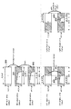
この様子を図1に示す。図1では、水平サイズin_w_all(=ot_w_all)、垂直サイズin_h_all(=ot_h_all)の入力画像(All input area)100の左側領域を左用の画像変形部、右側領域を右用の画像変形部にて画像変形させている。これにより、結果として、入力画像100を変形させた出力画像(All output area)101を得ている。
This is shown in FIG. In FIG. 1, the left region of the input image (All input area) 100 of the horizontal size in_w_all (= ot_w_all) and the vertical size in_h_all (= ot_h_all) 100 is the left image deformation unit, and the right region is the right image deformation unit. It is deformed. As a result, an output image (All output area) 101 obtained by deforming the
出力画像101の変形形状は、プロジェクタ製品のキーストーン補正処理であれば、プロジェクタからスクリーンまでの投影距離、縦/横設置角度、縦/横レンズシフトなどのパラメータで決定される。
The deformed shape of the
それぞれの画像変形部の水平出力サイズは等しく、ot_w_left=ot_w_right=(ot_w_all/2)であり、垂直入力/出力サイズも等しく、in_h_all=ot_h_allである。 The horizontal output sizes of the respective image transformation units are equal, ot_w_left = ot_w_right = (ot_w_all / 2), the vertical input / output sizes are also equal, and in_h_all = ot_h_all.
左用の画像変形部に着目すると、該画像変形部が水平出力サイズot_w_leftを出力するためには、left output areaに白色で図示される台形領域103を出力する必要がある。この台形領域103は、left input areaに白色で図示される矩形領域102に対応するので、該画像変形部で必要となる水平入力サイズin_w_left(>in_w_right)が算出できる。これは右用の画像変形部についても同様である。この結果、個々の画像変形部に入力すべき水平入力サイズin_w_left、in_w_rightが明らかになる。
Paying attention to the left image deformation unit, in order for the image deformation unit to output the horizontal output size ot_w_left, it is necessary to output a
ところで、個々の画像変形部で処理可能な入力サイズには通常、上限がある。この上限は、画像変形処理装置の動作周波数に起因する処理スループットや、構成要素として有する内部バッファ(例えばラインバッファの水平方向サイズ)や、構成要素として有するフレームメモリ(例えばDRAMの転送帯域)などによって決まる。 Incidentally, there is usually an upper limit on the input size that can be processed by the individual image transformation units. This upper limit depends on the processing throughput resulting from the operating frequency of the image transformation processing device, the internal buffer (for example, the horizontal size of the line buffer) as a component, the frame memory (for example, the DRAM transfer band) as a component, etc. Determined.
このため、個々の画像変形処理への水平入力サイズin_w_left、in_w_rightは、水平入力サイズの上限値以下にする必要がある。しかしながら、出力画像の有効領域に偏りのある変形の場合、個々の画像変形部への水平入力サイズin_w_left、in_w_rightにも偏りが生じ、結果として変形の度合いが小さい場合にも水平入力サイズの上限値を超えてしまうという問題がある。 For this reason, the horizontal input sizes in_w_left and in_w_right for individual image transformation processes need to be less than or equal to the upper limit of the horizontal input size. However, in the case of deformation with bias in the effective area of the output image, the horizontal input sizes in_w_left and in_w_right to the individual image deformation portions are also biased, and as a result, the upper limit value of the horizontal input size even when the degree of deformation is small There is a problem of exceeding.
次に、背景技術で挙げた先行技術について上記の問題が起こりえるかを説明する。まず、特許文献1には、出力画像の有効領域を決める方法が記載されておらず、出力画像の有効領域が任意の形状であった場合を例として説明がなされている。しかしながらこの方法では、個々の画像変形部の制限に応じて、出力画像の有効領域の位置を補正する構成を持たない。このため出力画像の有効領域の偏りを平均化することが出来ず、結果として変形の度合いが小さい場合にも水平入力サイズの上限値を超えてしまうという前述の問題が起こりえると言える。
Next, it will be described whether the above-mentioned problems can occur with respect to the prior art cited in the background art. First,
また、特許文献2では、出力画像の有効領域を決める方法として、スクリーン上に投影した4角形の頂点のうち、最も角度の大きな頂点を基準点として出力画像の有効領域を決める方法が示されている。具体的には特許文献2の”図4(a)投影画像”に示す投影画像の最大範囲を示す4角形の頂点のうち、最も角度の大きな”P0”を基準点としている。しかしながら、この方法では、出力画像の有効領域の偏りを平均化することができず、結果として変形の度合いが小さい場合にも水平入力サイズの上限値を超えてしまうという前述の問題が起こりえると言える。 Patent Document 2 discloses a method for determining an effective area of an output image by using, as a reference point, a vertex having the largest angle among quadrangular vertices projected on a screen as a method for determining an effective area of the output image. Yes. Specifically, “P0” having the largest angle among the vertices of the quadrangle indicating the maximum range of the projected image shown in “FIG. 4A” projected image of Patent Document 2 is used as a reference point. However, this method cannot average the bias of the effective area of the output image, and as a result, the above-described problem that the upper limit of the horizontal input size may be exceeded even when the degree of deformation is small may occur. I can say that.
またこの他にも、分割前の入力画像を全て表示できない場合があるという問題がある。具体的には、特許文献2の”図3(d)スクリーンに投影した画像”の左側画像の下部や、右側画像の上部が表示されないという現象がある。この現象があると、そもそも要件仕様を満たせない可能性があるという問題がある。 In addition to this, there is a problem that not all the input images before division may be displayed. Specifically, there is a phenomenon in which the lower part of the left side image and the upper part of the right side image of “Image projected onto the screen of FIG. If this phenomenon exists, there is a problem that it may not be possible to meet the requirement specification in the first place.
このように、先行技術では、出力画像の有効領域の偏りに起因する変形度合いの大幅な制限という課題がある。本発明は、このような問題に鑑みてなされたものであり、入力矩形画像を分割し、それぞれの分割画像を複数の画像変形部にて画像変形させる場合に、それぞれの分割画像の水平サイズを平均化するための技術を提供することを目的とする。 As described above, the prior art has a problem that the degree of deformation is largely limited due to the deviation of the effective area of the output image. The present invention has been made in view of such a problem. When an input rectangular image is divided and each divided image is deformed by a plurality of image deforming units, the horizontal size of each divided image is set. The purpose is to provide a technique for averaging.
本発明の目的を達成するために、例えば、本発明の画像処理装置は、入力画像の中心座標を特定する特定手段と、
前記入力画像に対する変形パラメータに基づく変形処理により得られる変形画像の中心座標と、前記特定手段により特定された前記入力画像の中心座標と、の差を取得する取得手段と、
前記取得手段により取得された差が小さくなるように前記変形画像の中心座標をシフトさせるシフト手段であって、前記取得手段により取得された差が大きいほど前記変形画像の中心座標を大きくシフトさせるシフト手段と、
前記シフト手段により中心座標がシフトされた変形画像の第1部分領域を前記入力画像と前記変形パラメータとに基づいて生成する第1処理手段と、前記変形画像の第2部分領域を前記入力画像と前記変形パラメータとに基づいて生成する第2処理手段と、を含む複数の処理手段と
を有することを特徴とする。
In order to achieve the object of the present invention, for example, an image processing apparatus of the present invention includes a specifying means for specifying a center coordinate of an input image,
An acquisition means for acquiring a difference between a center coordinate of a deformed image obtained by a deformation process based on a deformation parameter for the input image and a center coordinate of the input image specified by the specifying means;
Shift means for shifting the center coordinates of the deformed image so as to reduce the difference acquired by the acquiring means, and the shift for shifting the center coordinates of the deformed image by a larger amount as the difference acquired by the acquiring means is larger. Means,
First processing means for generating a first partial area of a deformed image whose center coordinates are shifted by the shift means based on the input image and the deformation parameter; and a second partial area of the deformed image as the input image. And a plurality of processing means including second processing means generated based on the deformation parameter.
本発明の構成によれば、入力矩形画像を分割し、それぞれの分割画像を複数の画像変形部にて画像変形させる場合に、それぞれの分割画像の水平サイズを平均化することができる。 According to the configuration of the present invention, when an input rectangular image is divided and each divided image is deformed by a plurality of image deforming units, the horizontal size of each divided image can be averaged.
以下、添付図面を参照し、本発明の好適な実施形態について説明する。なお、以下説明する実施形態は、本発明を具体的に実施した場合の一例を示すもので、特許請求の範囲に記載の構成の具体的な実施例の1つである。 Preferred embodiments of the present invention will be described below with reference to the accompanying drawings. The embodiment described below shows an example when the present invention is specifically implemented, and is one of the specific examples of the configurations described in the claims.
本実施形態に係る画像処理装置は、入力された入力矩形画像(静止画でも良いし、動画像中の各フレームの画像でも良い)を変形させてスクリーンなどの平面に対して投影する装置若しくは該装置に組み込まれる画像処理ユニットである。 The image processing apparatus according to the present embodiment is an apparatus that deforms an input input rectangular image (may be a still image or an image of each frame in a moving image) and projects the image on a plane such as a screen. An image processing unit incorporated in the apparatus.
本実施形態に係る画像処理装置の機能構成例について、図4のブロック図を用いて説明する。図4には、入力矩形画像から変形画像を生成するための主要な構成のみを記しており、画像投影を行う構成などについては省略している。 A functional configuration example of the image processing apparatus according to the present embodiment will be described with reference to the block diagram of FIG. FIG. 4 shows only a main configuration for generating a deformed image from an input rectangular image, and a configuration for performing image projection is omitted.
変形後形状決定部401は、入力矩形画像の形状を変形させる為の変形パラメータを用いて該入力矩形画像を変形させた場合に、該入力矩形画像の四隅の座標が写像される座標を、変形後形状として求める。
The post-deformation
ここで、変形パラメータとは、入力矩形画像と出力画像との対応関係を決める情報で、例えばプロジェクタ製品のキーストーン補正処理であれば、プロジェクタからスクリーンまでの投影距離、縦/横設置角度、縦/横レンズシフトから成るパラメータを含む。 Here, the deformation parameter is information that determines the correspondence between the input rectangular image and the output image. For example, in the case of keystone correction processing of a projector product, the projection distance from the projector to the screen, the vertical / horizontal installation angle, the vertical / Includes parameters consisting of lateral lens shift.
変形パラメータと変形後形状との関係は、入力矩形画像を変形後形状の4つの頂点で示される4角形に変形すると、変形パラメータで示されるプロジェクタの設置条件において、スクリーン上の投影領域は矩形になる。 The relationship between the deformation parameter and the deformed shape is that when the input rectangular image is deformed into a quadrangle indicated by the four vertices of the deformed shape, the projection area on the screen is rectangular under the projector installation conditions indicated by the deformation parameter. Become.
変形演算部402は、入力矩形画像の四隅の座標と、変形後形状と、を用いて、変形パラメータが表す3×3の写像行列(変形行列)を求める。この写像行列は、入力矩形画像の四隅の座標を、変形後形状の4つの頂点の座標に写像するための行列である。なお、変形パラメータが予めこの写像行列として与えられているのであれば、この写像行列を求める構成は省くことができる。以下では、この写像行列=変形パラメータとして説明する。
The
変形後オフセット計算部403は、入力矩形画像中の中心座標を求める。そして、変形パラメータを用いて入力矩形画像を変形させた場合に、該中心座標が写像される座標(写像座標)を求め、該求めた座標と該中心座標との差分を、「変形後画像の中心を出力画像の中心に移動させるためのオフセット量」として求める。
A post-deformation offset
入力画像サイズ計算部404は、このオフセット量を元に、入力矩形画像を左右2つの画像に分割する場合の、個々の分割画像のサイズを求め、該求めたサイズを入力画像分割部405に入力する。
Based on the offset amount, the input image
入力画像分割部405は、入力画像サイズ計算部404が求めたサイズに基づいて入力矩形画像を2つの分割画像に分割し、分割した一方の分割画像を画像変形部406に入力し、他方の分割画像を画像変形部407に入力する。
The input
画像変形部406及び画像変形部407は、入力された分割画像に対して変形処理を行い、変形後の画像を出力画像結合部408に対して出力する。出力画像結合部408は、画像変形部406及び画像変形部407から出力された変形後の画像を結合して1つの出力画像を形成してから変形後オフセット量だけ移動させ、出力同期信号と、出力画像とを装置外に出力する。ここでのオフセット方向は、後述の変形後オフセット量を求めた方向とは逆方向とする。出力先は画像投影を行う為の機能部(例えばプロジェクタ)であっても良いし、メモリであっても良い。また、ネットワークを介して他の機器であっても良い。
The
次に、変形後オフセット計算部403が行う処理について、同処理のフローチャートを示す図6を用いて説明する。ステップS601では、入力矩形画像(src画像)の中心点の座標(中心座標)を求める。図3では、入力矩形画像300の水平方向のサイズがin_w_all、垂直方向のサイズがin_h_allであるため、この場合は、以下の式に従って、入力矩形画像300の中心点307の座標(src_x、src_y)を求める。
Next, processing performed by the post-deformation offset
src_x = in_w_all/2−1
src_y = in_h_all/2−1
以下では、何れの画像であっても、左上隅の座標を(0,0)としている。
src_x = in_w_all / 2-1
src_y = in_h_all / 2-1
In the following, in any image, the coordinates of the upper left corner are (0, 0).
次に、ステップS602では、上記変形パラメータを用いて入力矩形画像を変形させた場合に、中心座標が写像される座標を求める。図3の場合、変形パラメータを用いて入力矩形画像300を変形させた変形画像(dst画像)301の中心点308の座標を求めることになる。
Next, in step S602, coordinates where the center coordinates are mapped when the input rectangular image is deformed using the deformation parameters are obtained. In the case of FIG. 3, the coordinates of the
具体的には、中心座標(src_x,src_y)を有する入力矩形画像300中の中心点307に対応する、変形画像301中の中心点308の座標DST_POINT(dst_x,dst_y)は、以下の式に従って求められる。
Specifically, the coordinates DST_POINT (dst_x, dst_y) of the
なおこの式において、s2d_offs_x_pre、s2d_offs_y_pre、s2d_offs_x_pst、s2d_offs_y_pst、m00〜m22の各係数は何れも、変形パラメータである。これらの変形パラメータは、src画像とdst画像との間の座標の関係から求められる。m00〜m22を算出する方法は公知のため、これに係る説明は省略する。s2d_offs_x_pre、s2d_offs_y_preは変形前に付加するオフセットであり、入力矩形画像にオフセットを付けて変形を行う場合に使用する。また、s2d_offs_x_pst、s2d_offs_y_pstは変形後に付加するオフセットであり、出力画像にオフセットを付けて変形を行う場合に使用する。これらの係数は変形形状を面内で移動する場合に使用するものであるが、本実施形態ではその必要はないため、いずれも0として説明を進める。 In this equation, each coefficient of s2d_offs_x_pre, s2d_offs_y_pre, s2d_offs_x_pst, s2d_offs_y_pst, m00 to m22 is a deformation parameter. These deformation parameters are obtained from the relationship of coordinates between the src image and the dst image. Since the method for calculating m00 to m22 is well known, the description relating to this is omitted. s2d_offs_x_pre and s2d_offs_y_pre are offsets to be added before the deformation, and are used when the input rectangular image is deformed with an offset. Further, s2d_offs_x_pst and s2d_offs_y_pst are offsets added after the deformation, and are used when the output image is deformed with an offset. These coefficients are used when the deformed shape is moved in the plane. However, in the present embodiment, these coefficients are not necessary, so that the description will be made assuming that both are zero.
次に、ステップS603では、ステップS601で求めた中心座標と、ステップS602で求めた座標と、の差分(変形後オフセット)diff_xを、以下の式に従って求める。 Next, in step S603, the difference (offset after deformation) diff_x between the center coordinates obtained in step S601 and the coordinates obtained in step S602 is obtained according to the following equation.
diff_x = rounddown(src_x−dst_x)
この計算は具体的には、DST_POINTとしてdst_xが求まったのち、この式で変形後オフセット:diff_xを求める。ここで、rounddown()は、小数点以下を切り捨て、整数を返す関数である。
diff_x = rounddown (src_x−dst_x)
Specifically, in this calculation, after dst_x is obtained as DST_POINT, the post-deformation offset: diff_x is obtained using this equation. Here, rounddown () is a function that truncates the decimal part and returns an integer.
ここで求めた変形後オフセット:diff_xは、変形後形状を出力画像の中心に移動するためのオフセット量である。このオフセットを適用すると、変形画像301に適用すると、図3に示す如く、変形画像301は、このオフセット分310だけ移動して変形画像302となり、中心点308も、このオフセット分310だけ移動して中心点309となる。これにより、出力画像中の中心点309の座標(写像中心座標)と、入力矩形画像300中の中心点307の座標と、は同じになる。
The post-deformation offset diff_x obtained here is an offset amount for moving the post-deformation shape to the center of the output image. When this offset is applied, when applied to the
次に、入力画像サイズ計算部404が行う処理について、同処理のフローチャートを示す図7を用いて説明する。
Next, processing performed by the input image
ステップS701では、src画像を変形させた画像であるdst画像の各頂点の座標を求める。図3の場合、入力矩形画像300の4頂点の座標SRC_POINT0〜3を下記の通り定義すれば、変形画像301の各頂点の座標DST_POINT0〜3は下記の式に従って計算することができる。
In step S701, the coordinates of each vertex of the dst image, which is an image obtained by deforming the src image, are obtained. In the case of FIG. 3, if the coordinates SRC_POINT0 to 3 of the four vertices of the input
次に、ステップS702では、ステップS701で求めた変形画像301の各頂点の座標DST_POINT0〜3に、上記のオフセットを加えることで、下記の式の如く、座標dst_x0〜3を求める。
Next, in step S702, coordinates dst_x0 to 3 are obtained by adding the above-described offset to the coordinates DST_POINT0 to 3 of each vertex of the
dst_x0〜3=dst_x0〜3+diff_x
この処理は、変形パラメータを用いて入力矩形画像を変形させた場合に、該入力矩形画像の四隅の座標が写像される座標を求め、該求めた座標に上記のオフセットを加算することで得られる座標を、写像四隅座標として求める処理である。
dst_x0-3 = dst_x0-3 + diff_x
This process is obtained by calculating coordinates where the coordinates of the four corners of the input rectangular image are mapped when the input rectangular image is deformed using the deformation parameter, and adding the offset to the determined coordinates. This is a process for obtaining the coordinates as the four corner coordinates of the mapping.
次に、ステップS703では、ステップS702求めたdst_x0〜3を用いて、出力可能なマージン量を計算する。具体的には下記の計算で求める。下記のot_x_margin0〜3の示す箇所を図3の303に示す。また、式中のMIN()は最小の値を返す関数である。
Next, in step S703, the output margin amount is calculated using dst_x0 to 3 obtained in step S702. Specifically, it is obtained by the following calculation. A portion indicated by
ot_x_margin0=(in_w_all/2−1)−dst_x0
ot_x_margin1=dst_x1−(in_w_all/2+1)
ot_x_margin2=dst_x2−(in_w_all/2+1)
ot_x_margin3=(in_w_all/2−1)−dst_x3
min_ot_x_margin=MIN(ot_x_margin0,ot_x_margin1,ot_x_margin2,ot_x_margin3)
この処理は、上記四隅のそれぞれの写像四隅座標と写像中心座標との間の、入力矩形画像の一辺(ここではx軸方向に沿った辺)に沿った方向の距離を求め、該求めた距離のうち最小の距離を求める処理である。
ot_x_margin0 = (in_w_all / 2-1) −dst_x0
ot_x_margin1 = dst_x1- (in_w_all / 2 + 1)
ot_x_margin2 = dst_x2- (in_w_all / 2 + 1)
ot_x_margin3 = (in_w_all / 2-1) −dst_x3
min_ot_x_margin = MIN (ot_x_margin0, ot_x_margin1, ot_x_margin2, ot_x_margin3)
This process determines the distance in the direction along one side (here, the side along the x-axis direction) of the input rectangular image between the four corner coordinates and the map center coordinates of each of the four corners. Is a process for obtaining the minimum distance.
ステップS704では、出力可能なマージン量(min_ot_x_margin)と、後段で必要とされる出力マージン量(req_ot_x_margin)と、メモリパッキング情報と、を用いて、出力マージン量(ot_x_margin)を計算する。 In step S704, the output margin amount (ot_x_margin) is calculated using the output margin amount (min_ot_x_margin), the output margin amount (req_ot_x_margin) required in the subsequent stage, and the memory packing information.
なお、メモリパッキング情報は、DRAMなどのフレームメモリ上にピクセルデータを配置する際の情報であり、以下の式中では32Byteに8pixelを配置する例を示している。具体的には下記の2つの関係式を満たし、かつ最小の値となる出力マージン量(ot_x_margin)を求める。 Note that the memory packing information is information when pixel data is arranged on a frame memory such as a DRAM, and an example in which 8 pixels are arranged in 32 bytes is shown in the following equation. Specifically, an output margin amount (ot_x_margin) satisfying the following two relational expressions and having a minimum value is obtained.
min_ot_x_margin≧ot_x_margin≧req_ot_x_margin
(ot_w_all/2)−ot_x_margin−1=8×N (Nは自然数)
次に、ステップS705では、出力マージン量(ot_x_margin)と、入力矩形画像の水平方向のサイズ(in_w_all)と、を用いて、入力マージン量(in_x_margin)を計算する。
min_ot_x_margin ≧ ot_x_margin ≧ req_ot_x_margin
(Ot_w_all / 2) −ot_x_margin−1 = 8 × N (N is a natural number)
Next, in step S705, the input margin amount (in_x_margin) is calculated using the output margin amount (ot_x_margin) and the horizontal size (in_w_all) of the input rectangular image.
この処理の概要を示すと、図3の入力矩形画像306における点321〜324の座標(src_x0〜3,src_y0〜3)を、変形画像305における点317〜320の座標(dst_x0〜3,dst_y0〜3)に変換する式を作る。ここで、点321〜324はそれぞれ点317〜320に対応する点であり、入力マージン量in_x_marginを算出するために用いる。次に、その式で表わされるdst_x0〜3と、変形画像305の点317〜320の4点とが等しくなるという関係式を、src_x0〜3について解き、in_x_margin0〜3を算出する。具体的には、まず以下のとおり変数をとる。
The outline of this processing is as follows. The coordinates (src_x0 to 3, src_y0 to 3) of the
src_x0_margin=(in_w_all/2)−ot_x_margin
src_x1_margin=((in_w_all/2)−1)+ot_x_margin
src_x2_margin=((in_w_all/2)−1)+ot_x_margin
src_x3_margin=(in_w_all/2) −ot_x_margin
src_y0=0
src_y1=0
src_y2=in_h_all−1
src_y3=in_h_all−1
次に以下の式でsrc_x[0〜3]を計算する。
src_x0_margin = (in_w_all / 2) −ot_x_margin
src_x1_margin = ((in_w_all / 2) -1) + ot_x_margin
src_x2_margin = ((in_w_all / 2) -1) + ot_x_margin
src_x3_margin = (in_w_all / 2) −ot_x_margin
src_y0 = 0
src_y1 = 0
src_y2 = in_h_all-1
src_y3 = in_h_all-1
Next, src_x [0-3] is calculated by the following equation.
src_x[0〜3]=−((m21*src_x[0〜3]_margin−m21*s2d_offs_x_pst−diff_x*m21−m01)*src_y[0〜3]
+(m21*s2d_offs_y_pre+m20*s2d_offs_x_pre+m22)*src_x[0〜3]_margin
+(−m21*s2d_offs_x_pst−diff_x*m21−m01)*s2d_offs_y_pre
+(−m20*s2d_offs_x_pre−m22)*s2d_offs_x_pst
+(−diff_x*m20−m00)*s2d_offs_x_pre−diff_x*m22−m02)
/(m20*src_x[0〜3]_margin−m20*s2d_offs_x_pst−diff_x*m20−m00)
この処理では、ようは、上記四隅のそれぞれの写像四隅座標と、写像中心座標と、の間の、水平方向の距離を求め、該求めた距離のうち最小の距離よりも小さい距離を出力マージン距離として決定している。そして、変形パラメータを用いて入力矩形画像を変形させた場合に、水平方向において写像中心座標から出力マージン距離だけ離間している座標に写像される写像元の座標を、写像元座標として求めている。
src_x [0-3] =-((m21 * src_x [0-3] _margin-m21 * s2d_offs_x_pst-diff_x * m21-m01) * src_y [0-3]
+ (M21 * s2d_offs_y_pre + m20 * s2d_offs_x_pre + m22) * src_x [0-3] _margin
+ (-M21 * s2d_offs_x_pst-diff_x * m21-m01) * s2d_offs_y_pre
+ (-M20 * s2d_offs_x_pre-m22) * s2d_offs_x_pst
+ (-Diff_x * m20-m00) * s2d_offs_x_pre-diff_x * m22-m02)
/ (M20 * src_x [0-3] _margin-m20 * s2d_offs_x_pst-diff_x * m20-m00)
In this process, the horizontal distance between the mapping four corner coordinates of each of the four corners and the mapping center coordinates is obtained, and a distance smaller than the minimum distance among the obtained distances is set as an output margin distance. As determined. Then, when the input rectangular image is deformed using the deformation parameter, the coordinates of the mapping source mapped to the coordinates that are separated from the mapping center coordinate by the output margin distance in the horizontal direction are obtained as the mapping source coordinates. .
図3の場合、変形画像305における中心点から315,316で示す出力マージン距離だけ水平方向に離間した位置の点317〜320の座標に写像される写像元の点321〜324の座標を、写像元座標として求めている。
In the case of FIG. 3, the coordinates of the mapping source points 321 to 324 mapped to the coordinates of the
次に以下の式でin_x_margin[0〜3]を計算する。式中のFLOOR()は小数点を切り捨てて整数を返す関数、CEILING()は小数切り上げで整数を返す関数である。 Next, in_x_margin [0 to 3] is calculated using the following equation. FLOOR () in the expression is a function that truncates the decimal point and returns an integer, and CEILING () is a function that returns an integer by rounding up the decimal.
in_x_margin0=1+(in_w_all/2) −FLOOR(src_x0)
in_x_margin1=1−(in_w_all/2−1) +CEILING(src_x1)
in_x_margin2=1−(in_w_all/2−1) +CEILING(src_x2)
in_x_margin3=1+(in_w_all/2) −FLOOR(src_x3)
そして、以下の式を計算することで、入力マージン(in_x_margin)を求める。
in_x_margin0 = 1 + (in_w_all / 2) −FLOOR (src_x0)
in_x_margin1 = 1− (in_w_all / 2-1) + CEILING (src_x1)
in_x_margin2 = 1− (in_w_all / 2-1) + CEILING (src_x2)
in_x_margin3 = 1 + (in_w_all / 2) −FLOOR (src_x3)
Then, an input margin (in_x_margin) is obtained by calculating the following expression.
in_x_margin=MAX(in_x_margin0, in_x_margin1, in_x_margin2, in_x_margin3)
入力マージン(in_x_margin)が決定すると、画像変形部406及び画像変形部407のそれぞれに入力する分割画像の水平方向のサイズは、下記の通り決定する。
in_x_margin = MAX (in_x_margin0, in_x_margin1, in_x_margin2, in_x_margin3)
When the input margin (in_x_margin) is determined, the horizontal size of the divided image input to each of the
(in_w_all/2)+in_x_margin
この処理では、それぞれの写像元座標と写像中心座標との間の水平方向における距離を求め、該求めた距離のうち最大の距離を入力マージン距離として決定している。そして、入力矩形画像の水平方向におけるサイズの半分に入力マージン距離を加えた結果を、分割画像水平サイズとして求めている。
(In_w_all / 2) + in_x_margin
In this process, the horizontal distance between each mapping source coordinate and the mapping center coordinate is obtained, and the maximum distance among the obtained distances is determined as the input margin distance. The result obtained by adding the input margin distance to half the size of the input rectangular image in the horizontal direction is obtained as the divided image horizontal size.
画像変形部406には、入力矩形画像において座標(0,0)を左上隅、座標((in_w_all/2)+in_x_margin−1,in_h_all−1)を右下隅とする領域内の画像を入力することになる。また、画像変形部407には、入力矩形画像において座標((in_w_all/2)−in_x_margin,0)を左上隅、座標(in_w_all−1,in_h_all−1)を右下隅とする領域内の画像を入力することになる。
In the
即ち、入力矩形画像の左辺からの距離が該分割画像水平サイズ以内となる領域内の画像、入力矩形画像の右辺からの距離が該分割画像水平サイズ以内となる領域内の画像、のそれぞれの形状を変形させてから出力することになる。 That is, the shape of the image in the region where the distance from the left side of the input rectangular image is within the horizontal size of the divided image, and the shape of the image in the region where the distance from the right side of the input rectangular image is within the horizontal size of the divided image Will be output after being transformed.
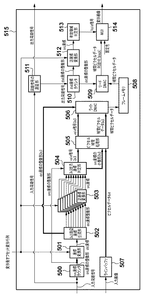
次に、画像変形部406及び画像変形部407の機能構成例について、図5のブロック図を用いて説明する。画像変形部406及び画像変形部407の何れも同様の構成を有しているため、図5では、画像変形部406及び画像変形部407を画像変形部515として示している。
Next, functional configuration examples of the
画像変形部515は、入力同期信号と入力矩形画像とに対して、変形後オフセットと変形パラメータにもとづいて変形処理を行い、出力同期信号と変形画像を出力する。画像変形を行うための構成として、本実施形態ではフレームメモリの前段でランダムアクセスを行い、後段で順次アクセスを行う構成をとっている。なお、以下では変形前のsrc画像中の座標をsrc座標、dst画像中の座標をdst座標と呼ぶ。
The
入力同期信号はsrc座標カウンタ500に入力され、内部カウンタで座標をカウントしてsrc座標の整数部を出力する。座標変換部501は、src座標の整数部をdst座標に変換して、3x3周辺座標生成部502に入力する。
The input synchronization signal is input to the src coordinate counter 500, and the internal counter counts the coordinates and outputs the integer part of the src coordinates. The coordinate
座標変換部501が行う処理をより詳細に説明すると、上記の処理で算出した変形後オフセットdiff_xと、変形パラメータと、にもとづいて、入力矩形画像の各座標SRC_POINTに対応する出力画像の座標DST_POINTを計算する。この処理は以下の式で表わされる。この処理により、変形後オフセットと変形パラメータにもとづいて変形処理が行われる。
The process performed by the coordinate
3x3周辺座標生成部502は、入力されたdst座標を中心とした周辺3×3画素のdst座標を生成して出力する。逆座標変換部503は9つ配置され、dst座標整数部を逆変換して9つのsrc座標を出力する。
The 3 × 3 peripheral coordinate
このsrc座標は3x3出力座標判定部504に入力され、src座標カウンタ500から入力されるsrc座標の整数部と比較され、valid信号3x3分とsrc座標の小数部3x3分が出力される。
The src coordinates are input to the 3 × 3 output coordinate
一方、画像変形部515に入力された入力矩形画像は、ラインバッファ507に一旦保持された後、4×4画素の16画素分のピクセルデータが出力される。本実施形態では、ピクセル補間方式をバイキュービック方式と仮定したため、4×4画素のピクセルデータを出力するようにしたが、補間方式が異なれば参照範囲は4×4画素でなくてもよい。
On the other hand, the input rectangular image input to the
ピクセル補間処理部505は、valid信号3×3と、src座標の小数部3×3と、ピクセルデータ4×4を入力とし、valid信号3×3と補間ピクセルデータ3×3を出力する。Valid信号3×3は入力をそのまま出力し、補間ピクセルデータ3×3は、入力されたピクセルデータ4×4を参照して、バイキュービック補間方式でピクセル補間したデータ3×3点分を出力する。
The pixel
次に、ライトDMAC506にて、補間ピクセルデータ3×3点分のデータは、valid信号3×3が有効なもののみdst座標の整数部3×3で指定されるアドレスにメモリライトされる。出力された補間ピクセルデータはフレームメモリ508に保持される。
Next, in the
次に図5の画像変形部515のメモリリードより後段の部分を説明する。入力同期信号は、同期信号の遅延部511に入力され、出力同期信号が生成される。画像変形部515の後段部分は、上記の、遅延して生成された出力同期信号によって駆動される。
Next, a part subsequent to the memory read of the
出力同期信号はdst座標カウンタ510に入力され、dst座標の整数部が内部カウンタで生成されて出力される。リードDMAC509は、dst座標の整数部で指定されるアドレスの補間ピクセルデータをフレームメモリ508から取得する。
The output synchronization signal is input to the dst coordinate counter 510, and the integer part of the dst coordinate is generated and output by the internal counter. The
逆座標変換部512は、dst座標の整数部を入力とし、src座標を生成する。src座標は有効領域判定部513に入力され、該当のsrc座標が有効な領域にあるか、無効な領域にあるかを判定し、valid信号を出力する。ここでsrc座標が入力矩形画像の領域外(負の領域または、正の方向にin_w_all、in_h_all以上の領域)となった場合は、dst座標カウンタ510で生成されたdst座標に対応するsrc座標は無いため、valid信号は0が出力される。一方、その逆の場合は有効な領域にあることを示しているのでvalid信号は1が出力される。
The inverse coordinate
最後にMUX514は、入力される補間ピクセルデータと固定色をvalid信号にもとづいて選択し、変形画像として出力する。固定色はプロジェクタの例では台形外の領域であり、一般には黒色が出力される。
Finally, the
次に、上記の処理による効果について、図2を用いて説明する。図2は、図1に対応させた、本実施形態の画像変形例を示したものである。図1および図2の各分割画像の水平入力サイズ(in_w_left、in_w_right)より、本実施形態の構成により水平入力サイズが平均化されていることがわかる。より具体的には、図2において左右にそれぞれ入力すべき画像は、左側入力画像が画像203、右側入力画像が画像205となり、これは図1の左側の矩形領域102および右側の矩形領域104と比較すると水平サイズが平均化されている。このことにより、左側出力画像204と右側出力画像206の有効領域の偏りを軽減することができ、結果として同じハードウエアリソースで、より広い変形度合いをサポートすることが可能となる。
Next, the effect of the above processing will be described with reference to FIG. FIG. 2 shows an image modification example of the present embodiment corresponding to FIG. From the horizontal input size (in_w_left, in_w_right) of each divided image in FIGS. 1 and 2, it can be seen that the horizontal input size is averaged by the configuration of the present embodiment. More specifically, the images to be input to the left and right in FIG. 2 are the
なお、上記の説明では、入力矩形画像を左右2つに分割する構成を示したが、分割の方法はこれに限ったものではなく、上下2分割や、それらを組み合わせた田の字型の分割などであってもよい。 In the above description, the configuration in which the input rectangular image is divided into two parts on the left and right is shown. However, the dividing method is not limited to this. It may be.
(その他の実施例)
また、本発明は、以下の処理を実行することによっても実現される。即ち、上述した実施形態の機能を実現するソフトウェア(プログラム)を、ネットワーク又は各種記憶媒体を介してシステム或いは装置に供給し、そのシステム或いは装置のコンピュータ(またはCPUやMPU等)がプログラムを読み出して実行する処理である。
(Other examples)
The present invention can also be realized by executing the following processing. That is, software (program) that realizes the functions of the above-described embodiments is supplied to a system or apparatus via a network or various storage media, and a computer (or CPU, MPU, or the like) of the system or apparatus reads the program. It is a process to be executed.
Claims (11)
前記入力画像に対する変形パラメータに基づく変形処理により得られる変形画像の中心座標と、前記特定手段により特定された前記入力画像の中心座標と、の差を取得する取得手段と、
前記取得手段により取得された差が小さくなるように前記変形画像の中心座標をシフトさせるシフト手段であって、前記取得手段により取得された差が大きいほど前記変形画像の中心座標を大きくシフトさせるシフト手段と、
前記シフト手段により中心座標がシフトされた変形画像の第1部分領域を前記入力画像と前記変形パラメータとに基づいて生成する第1処理手段と、前記変形画像の第2部分領域を前記入力画像と前記変形パラメータとに基づいて生成する第2処理手段と、を含む複数の処理手段と
を有することを特徴とする画像処理装置。 A specifying means for specifying the center coordinates of the input image;
An acquisition means for acquiring a difference between a center coordinate of a deformed image obtained by a deformation process based on a deformation parameter for the input image and a center coordinate of the input image specified by the specifying means;
Shift means for shifting the center coordinates of the deformed image so as to reduce the difference acquired by the acquiring means, and the shift for shifting the center coordinates of the deformed image by a larger amount as the difference acquired by the acquiring means is larger. Means,
First processing means for generating a first partial area of a deformed image whose center coordinates are shifted by the shift means based on the input image and the deformation parameter; and a second partial area of the deformed image as the input image. And a plurality of processing means including second processing means generated based on the deformation parameter.
前記第1処理手段は、前記複数の分割画像のうちの第1分割画像に対する変形処理によって前記第1部分領域を生成し、前記第2処理手段は、前記複数の分割画像のうち第2分割画像に対する変形処理によって前記第2部分領域を生成することを特徴とする請求項1に記載の画像処理装置。 Dividing means for dividing the input image into a plurality of divided images;
The first processing unit generates the first partial region by a deformation process on the first divided image among the plurality of divided images, and the second processing unit generates a second divided image among the plurality of divided images. The image processing apparatus according to claim 1, wherein the second partial region is generated by a deformation process on the image.
前記結合手段により生成された出力画像を出力する出力手段と
を有することを特徴とする請求項1乃至3の何れか1項に記載の画像処理装置。 A combining unit that executes a combining process on the plurality of deformed images obtained by the deformation process by the plurality of processing units to generate an output image;
The image processing apparatus according to any one of claims 1 to 3, characterized in that an output means for outputting an output image generated by the coupling means.
前記変形パラメータは、前記プロジェクタの縦傾き角、横傾き角、レンズ状態、及び前記プロジェクタとスクリーンとの間の距離、のうち少なくとも1つを含む光学パラメータに基づいて決定されることを特徴とする請求項1乃至4の何れか1項に記載の画像処理装置。 The image processing apparatus is a projector,
The deformation parameter is determined based on an optical parameter including at least one of a vertical tilt angle, a horizontal tilt angle, a lens state, and a distance between the projector and a screen of the projector. the image processing apparatus according to any one of claims 1 to 4.
前記入力画像に対する変形パラメータに基づく変形処理により得られる変形画像の中心座標と、前記特定工程で特定された前記入力画像の中心座標と、の差を取得する取得工程と、
前記取得工程で取得された差が小さくなるように前記変形画像の中心座標をシフトさせるシフト工程であって、前記取得工程で取得された差が大きいほど前記変形画像の中心座標を大きくシフトさせるシフト工程と、
前記シフト工程で中心座標がシフトされた変形画像の第1部分領域を前記入力画像と前記変形パラメータとに基づいて生成する第1処理工程と、前記変形画像の第2部分領域を前記入力画像と前記変形パラメータとに基づいて生成する第2処理工程と、を含む複数の処理工程と
を有することを特徴とする画像処理方法。 A specific step of specifying the center coordinates of the input image;
An acquisition step of acquiring a difference between a center coordinate of a deformed image obtained by a deformation process based on a deformation parameter for the input image and a center coordinate of the input image specified in the specifying step;
A shift step of shifting the center coordinates of the deformed image as has been acquired by the acquisition step becomes small, the shift to significantly shift the center coordinates of the deformed image larger the obtained difference by said acquisition step Process,
A first processing step for generating a first partial region of the deformed image whose center coordinates are shifted in the shifting step based on the input image and the deformation parameter; and a second partial region of the deformed image as the input image. A plurality of processing steps including a second processing step generated based on the deformation parameter.
前記第1処理工程では、前記複数の分割画像のうちの第1分割画像に対する変形処理によって前記第1部分領域を生成し、前記第2処理工程では、前記複数の分割画像のうち第2分割画像に対する変形処理によって前記第2部分領域を生成することを特徴とする請求項6に記載の画像処理方法。 A dividing step of dividing the input image into a plurality of divided images;
In the first processing step, the first partial region is generated by a deformation process on the first divided image among the plurality of divided images, and in the second processing step, a second divided image among the plurality of divided images. The image processing method according to claim 6 , wherein the second partial region is generated by a deformation process on the image.
前記結合工程で生成された出力画像を出力する出力工程と
を有することを特徴とする請求項6乃至8の何れか1項に記載の画像処理方法。 A combining step of generating an output image by executing a combining process on the plurality of deformed images obtained by the deformation processing in the plurality of processing steps;
The image processing method according to claim 6 , further comprising an output step of outputting the output image generated in the combining step.
前記変形パラメータは、前記プロジェクタの縦傾き角、横傾き角、レンズ状態、及び前記プロジェクタとスクリーンとの間の距離、のうち少なくとも1つを含む光学パラメータに基づいて決定されることを特徴とする請求項6乃至9の何れか1項に記載の画像処理方法。 The image processing method is executed by a projector,
The deformation parameter is determined based on an optical parameter including at least one of a vertical tilt angle, a horizontal tilt angle, a lens state, and a distance between the projector and a screen of the projector. the image processing method according to any one of claims 6-9.
Priority Applications (5)
| Application Number | Priority Date | Filing Date | Title |
|---|---|---|---|
| JP2012094178A JP6000613B2 (en) | 2012-04-17 | 2012-04-17 | Image processing apparatus and image processing method |
| EP13162287.0A EP2654304A3 (en) | 2012-04-17 | 2013-04-04 | Image processing apparatus and image processing method |
| US13/858,298 US9082186B2 (en) | 2012-04-17 | 2013-04-08 | Image processing apparatus and image processing method |
| CN201310130840.5A CN103379241B (en) | 2012-04-17 | 2013-04-16 | Image processing apparatus and image processing method |
| US14/739,023 US9332238B2 (en) | 2012-04-17 | 2015-06-15 | Image processing apparatus and image processing method |
Applications Claiming Priority (1)
| Application Number | Priority Date | Filing Date | Title |
|---|---|---|---|
| JP2012094178A JP6000613B2 (en) | 2012-04-17 | 2012-04-17 | Image processing apparatus and image processing method |
Publications (3)
| Publication Number | Publication Date |
|---|---|
| JP2013222349A JP2013222349A (en) | 2013-10-28 |
| JP2013222349A5 JP2013222349A5 (en) | 2015-06-18 |
| JP6000613B2 true JP6000613B2 (en) | 2016-09-28 |
Family
ID=48128077
Family Applications (1)
| Application Number | Title | Priority Date | Filing Date |
|---|---|---|---|
| JP2012094178A Expired - Fee Related JP6000613B2 (en) | 2012-04-17 | 2012-04-17 | Image processing apparatus and image processing method |
Country Status (4)
| Country | Link |
|---|---|
| US (2) | US9082186B2 (en) |
| EP (1) | EP2654304A3 (en) |
| JP (1) | JP6000613B2 (en) |
| CN (1) | CN103379241B (en) |
Families Citing this family (5)
| Publication number | Priority date | Publication date | Assignee | Title |
|---|---|---|---|---|
| JP5924020B2 (en) * | 2012-02-16 | 2016-05-25 | セイコーエプソン株式会社 | Projector and projector control method |
| JP6306834B2 (en) * | 2013-07-24 | 2018-04-04 | キヤノン株式会社 | Image processing apparatus and image processing method |
| JP6252577B2 (en) * | 2015-10-13 | 2017-12-27 | コニカミノルタ株式会社 | Image processing apparatus and image processing method |
| KR101686823B1 (en) * | 2015-12-14 | 2016-12-16 | 인천대학교 산학협력단 | Spinning Image Generation and method thereof |
| CN110390630A (en) * | 2018-04-17 | 2019-10-29 | 上海碧虎网络科技有限公司 | Image distortion method, device, storage medium, display system and automobile |
Family Cites Families (11)
| Publication number | Priority date | Publication date | Assignee | Title |
|---|---|---|---|---|
| JP3735158B2 (en) | 1996-06-06 | 2006-01-18 | オリンパス株式会社 | Image projection system and image processing apparatus |
| JP3951984B2 (en) * | 2003-08-22 | 2007-08-01 | 日本電気株式会社 | Image projection method and image projection apparatus |
| JP2006113371A (en) | 2004-10-15 | 2006-04-27 | Seiko Epson Corp | Image display device |
| JP3953500B1 (en) * | 2006-02-07 | 2007-08-08 | シャープ株式会社 | Image projection method and projector |
| JP2008312099A (en) | 2007-06-18 | 2008-12-25 | Victor Co Of Japan Ltd | Projected image correcting equipment and projection equipment |
| JP2010152267A (en) | 2008-12-26 | 2010-07-08 | Seiko Epson Corp | Projector |
| JP5436080B2 (en) | 2009-07-21 | 2014-03-05 | キヤノン株式会社 | Image projection device |
| JP5744418B2 (en) * | 2010-05-18 | 2015-07-08 | キヤノン株式会社 | Projection apparatus and projection method |
| JP5676924B2 (en) * | 2010-06-07 | 2015-02-25 | キヤノン株式会社 | Projection apparatus and projection method |
| JP5146700B2 (en) * | 2010-06-10 | 2013-02-20 | セイコーエプソン株式会社 | Keystone correction method |
| JP5839785B2 (en) | 2010-07-06 | 2016-01-06 | キヤノン株式会社 | Projection system, projection apparatus, and imaging apparatus |
-
2012
- 2012-04-17 JP JP2012094178A patent/JP6000613B2/en not_active Expired - Fee Related
-
2013
- 2013-04-04 EP EP13162287.0A patent/EP2654304A3/en not_active Withdrawn
- 2013-04-08 US US13/858,298 patent/US9082186B2/en not_active Expired - Fee Related
- 2013-04-16 CN CN201310130840.5A patent/CN103379241B/en not_active Expired - Fee Related
-
2015
- 2015-06-15 US US14/739,023 patent/US9332238B2/en not_active Expired - Fee Related
Also Published As
| Publication number | Publication date |
|---|---|
| US20130271494A1 (en) | 2013-10-17 |
| JP2013222349A (en) | 2013-10-28 |
| EP2654304A3 (en) | 2017-08-16 |
| US9332238B2 (en) | 2016-05-03 |
| CN103379241B (en) | 2015-10-14 |
| CN103379241A (en) | 2013-10-30 |
| EP2654304A2 (en) | 2013-10-23 |
| US9082186B2 (en) | 2015-07-14 |
| US20150281662A1 (en) | 2015-10-01 |
Similar Documents
| Publication | Publication Date | Title |
|---|---|---|
| KR101785027B1 (en) | Image distortion compensation display device and image distortion compensation method using the same | |
| JP6568223B2 (en) | Projection device, projection method, and projection program | |
| KR100525425B1 (en) | Image warping method and apparatus | |
| JP6000613B2 (en) | Image processing apparatus and image processing method | |
| US8928782B2 (en) | Image processing device and image capture device | |
| JP4871820B2 (en) | Video display system and parameter generation method for the system | |
| US20100321408A1 (en) | Viewpoint Compensation for Curved Display Surfaces in Projector-Based Display Systems | |
| JP2014171030A (en) | Image processing apparatus, projector, and image processing method | |
| JP2012238171A (en) | Image processing device, image processing method and program | |
| JP2011193332A (en) | Projector and video projection method | |
| JP5116740B2 (en) | Image processing apparatus, image processing method, and image display apparatus | |
| US11893706B2 (en) | Image correction device | |
| US10713757B2 (en) | Image processing apparatus, control method thereof, and storage medium | |
| US20120050304A1 (en) | Image processing apparatus, method, and program | |
| JP2011050054A (en) | Method and device for generating display mask, and computer readable storage medium | |
| JP6316010B2 (en) | Image processing apparatus and image processing method | |
| JP5787637B2 (en) | Image processing apparatus and image processing method | |
| JP2017017672A (en) | Image processing apparatus, image processing method, and image processing program | |
| JPH0737079A (en) | Method and device for correcting picture distortion | |
| JP2019125830A (en) | Image output apparatus, projection apparatus, control method thereof, system, and program | |
| JP2013257665A (en) | Movie processing apparatus and control method therefor | |
| JP6273881B2 (en) | Image processing apparatus, image processing method, and program | |
| CN110363715A (en) | A Photo Angle Correction Method Based on Digital Image Processing | |
| JP2017016511A (en) | Distortion-corrected image processing apparatus and program | |
| JP2020038730A (en) | Image processing apparatus, image processing method, and program |
Legal Events
| Date | Code | Title | Description |
|---|---|---|---|
| A621 | Written request for application examination |
Free format text: JAPANESE INTERMEDIATE CODE: A621 Effective date: 20150417 |
|
| A521 | Request for written amendment filed |
Free format text: JAPANESE INTERMEDIATE CODE: A523 Effective date: 20150424 |
|
| A977 | Report on retrieval |
Free format text: JAPANESE INTERMEDIATE CODE: A971007 Effective date: 20160128 |
|
| A131 | Notification of reasons for refusal |
Free format text: JAPANESE INTERMEDIATE CODE: A131 Effective date: 20160201 |
|
| A521 | Request for written amendment filed |
Free format text: JAPANESE INTERMEDIATE CODE: A523 Effective date: 20160324 |
|
| TRDD | Decision of grant or rejection written | ||
| A01 | Written decision to grant a patent or to grant a registration (utility model) |
Free format text: JAPANESE INTERMEDIATE CODE: A01 Effective date: 20160805 |
|
| A61 | First payment of annual fees (during grant procedure) |
Free format text: JAPANESE INTERMEDIATE CODE: A61 Effective date: 20160831 |
|
| R151 | Written notification of patent or utility model registration |
Ref document number: 6000613 Country of ref document: JP Free format text: JAPANESE INTERMEDIATE CODE: R151 |
|
| LAPS | Cancellation because of no payment of annual fees |