JP2017016511A - Distortion correction image processor and program - Google Patents
Distortion correction image processor and program Download PDFInfo
- Publication number
- JP2017016511A JP2017016511A JP2015134419A JP2015134419A JP2017016511A JP 2017016511 A JP2017016511 A JP 2017016511A JP 2015134419 A JP2015134419 A JP 2015134419A JP 2015134419 A JP2015134419 A JP 2015134419A JP 2017016511 A JP2017016511 A JP 2017016511A
- Authority
- JP
- Japan
- Prior art keywords
- lut
- correction
- coordinate
- value
- offset
- Prior art date
- Legal status (The legal status is an assumption and is not a legal conclusion. Google has not performed a legal analysis and makes no representation as to the accuracy of the status listed.)
- Pending
Links
- 238000012937 correction Methods 0.000 title claims abstract description 167
- 230000006835 compression Effects 0.000 claims abstract description 52
- 238000007906 compression Methods 0.000 claims abstract description 52
- 238000006243 chemical reaction Methods 0.000 claims abstract description 43
- 238000003702 image correction Methods 0.000 claims abstract description 18
- 238000012545 processing Methods 0.000 claims description 99
- 238000011161 development Methods 0.000 claims description 9
- 230000015654 memory Effects 0.000 description 30
- 230000003287 optical effect Effects 0.000 description 18
- 238000000034 method Methods 0.000 description 13
- 238000010586 diagram Methods 0.000 description 8
- 238000004364 calculation method Methods 0.000 description 7
- 230000006870 function Effects 0.000 description 7
- 238000001914 filtration Methods 0.000 description 5
- 230000008569 process Effects 0.000 description 4
- 241000226585 Antennaria plantaginifolia Species 0.000 description 2
- 230000004075 alteration Effects 0.000 description 2
- 238000013507 mapping Methods 0.000 description 2
- 238000004422 calculation algorithm Methods 0.000 description 1
- 230000015556 catabolic process Effects 0.000 description 1
- 238000004590 computer program Methods 0.000 description 1
- 230000006837 decompression Effects 0.000 description 1
- 238000006731 degradation reaction Methods 0.000 description 1
- 238000001514 detection method Methods 0.000 description 1
- 230000014509 gene expression Effects 0.000 description 1
- 238000004519 manufacturing process Methods 0.000 description 1
- 238000005259 measurement Methods 0.000 description 1
- 238000012986 modification Methods 0.000 description 1
- 230000004048 modification Effects 0.000 description 1
- 238000007781 pre-processing Methods 0.000 description 1
- 230000002441 reversible effect Effects 0.000 description 1
- 238000012546 transfer Methods 0.000 description 1
- 230000003936 working memory Effects 0.000 description 1
Images


Abstract
Description
本発明は,画像データの歪みを補正するための機能を有する画像処理装置及びプログラムに関する。具体的に説明すると,本発明は,ピクセル単位で歪み補正を行うためのLUT(Look Up Table:ルックアップテーブル)を予め作成しておき,画像データが入力されたときにこのLUTを参照して画像の歪み補正処理を行う装置及びプログラムに関するものである。 The present invention relates to an image processing apparatus and a program having a function for correcting distortion of image data. More specifically, in the present invention, an LUT (Look Up Table) for correcting distortion in units of pixels is created in advance, and this LUT is referred to when image data is input. The present invention relates to an apparatus and a program for performing image distortion correction processing.
一般的な光学レンズには収差が存在するため,光学レンズによって取得された画像データ(写真及び動画)には,その光学レンズの光学的形状に応じた歪みが発生することが知られている。光学的形状に応じた歪みとしては,糸巻形状や樽形状の歪みが知られている。また,光学レンズには個体差があり,光学レンズ毎に画像データに生じる歪みの形状が異なることがある。このため,光学レンズによって取得された画像データをフラットなディスプレイに表示する場合には,歪みを持つ画像データを,本来のフラットな形状に戻す処理を行う必要がある。他方で,歪みを持ったディスプレイ,例えば車載型のカーナビゲーション装置に用いられる透過ヘッドアップディスプレイに対して,GPU(Graphics Processing Unit)によって生成された歪みのない画像データ(コンピュータグラフィックス)を表示させる場合もある。この場合には,GPUで生成された画像データに対して,そのディスプレイに応じた歪みを与える補正処理を行うことで,歪みをもったディスプレイであっても,使用者に歪みを感じさせないように画像を表示することが可能となる。このように,歪みを持たない画像データを,歪ませる補正処理を行うこともある。 Since there is aberration in a general optical lens, it is known that distortion corresponding to the optical shape of the optical lens occurs in image data (photographs and moving images) acquired by the optical lens. As the distortion according to the optical shape, a pincushion shape or barrel shape distortion is known. In addition, there are individual differences in optical lenses, and the shape of distortion that occurs in image data may differ from one optical lens to another. For this reason, when displaying the image data acquired by the optical lens on a flat display, it is necessary to perform processing for returning the image data having distortion to the original flat shape. On the other hand, undistorted image data (computer graphics) generated by a GPU (Graphics Processing Unit) is displayed on a distorted display, for example, a transparent head-up display used in an in-car car navigation system. In some cases. In this case, the image data generated by the GPU is subjected to correction processing that gives distortion corresponding to the display so that the user does not feel the distortion even if the display has distortion. An image can be displayed. As described above, correction processing for distorting image data having no distortion may be performed.
ここで,従来から,画像データの歪みを補正する処理において,LUTを利用することが知られている(特許文献1)。歪み補正用のLUTは,ピクセル毎に,歪み補正前のデータの座標値と歪み補正後の座標値とを対応付けて記憶している。このため,歪みが発生している領域内のピクセルを処理するときに,このLUTを参照すれば,量産時に発生するレンズ歪みの個体差を1ピクセル単位で補正することができる。このようにして,LUTを設定することで,光学レンズ等の光学的形状に応じた画像の歪みを補正し,歪みが解消された座標値を得ることができる。 Here, conventionally, it is known to use an LUT in processing for correcting distortion of image data (Patent Document 1). The distortion correction LUT stores, for each pixel, a coordinate value of data before distortion correction and a coordinate value after distortion correction in association with each other. Therefore, by referring to this LUT when processing pixels in a region where distortion occurs, individual differences in lens distortion occurring during mass production can be corrected in units of one pixel. In this way, by setting the LUT, it is possible to correct the image distortion according to the optical shape of the optical lens or the like, and obtain a coordinate value in which the distortion is eliminated.
しかしながら,LUTを利用して歪み補正を行う場合,ピクセルごとに補正後の座標値を定義する必要がある。従って,歪み補正用のLUTは,その情報量(データ量)が大きくなり,メモリの記憶空間を圧迫するという問題があった。また,LUTの情報量が大きいと,そのLUTを読み出すのに時間が掛かるため,画像処理装置全体において処理の遅延や性能の低下を招くおそれがある。そこで,本発明は,歪み補正用のLUTを効率的に圧縮して情報量の低減を図り,LUTの読み出し性能や,画像処理装置全体の処理速度及び処理性能を向上させることを目的としている。 However, when performing distortion correction using an LUT, it is necessary to define a corrected coordinate value for each pixel. Therefore, the distortion correction LUT has a problem in that the amount of information (data amount) is large and the storage space of the memory is compressed. In addition, if the amount of information in the LUT is large, it takes time to read the LUT, which may cause processing delay and performance degradation in the entire image processing apparatus. Accordingly, an object of the present invention is to reduce the amount of information by efficiently compressing a distortion correction LUT to improve the LUT read performance, the processing speed and the processing performance of the entire image processing apparatus.
本発明の発明者らは,従来発明の問題点を解決する手段について鋭意検討した結果,歪み補正前後の座標値のオフセット値(差分値)を,所定のオフセットコードと対応付けておき,このオフセットコードを利用して歪み補正用のLUTを圧縮するという知見を得た。このようにLUTを圧縮することで,LUTの情報量を効率的に低減させることができるため,画像処理装置の処理速度及び処理性能を向上させることが可能である。また,LUTを圧縮することで,その圧縮によって生じた余剰空間に,その他のピクセルごとの処理情報(例えば,切り出しに関わるマスク情報や,画像ID,輝度調整用の情報)を格納することもできるようになる。そして,本発明者らは,上記知見に基づけば,従来発明の問題を解決できることに想到し,本発明を完成させた。具体的に説明すると,本発明は以下の構成を有する。 As a result of intensive studies on means for solving the problems of the conventional invention, the inventors of the present invention associate an offset value (difference value) of coordinate values before and after distortion correction with a predetermined offset code, and this offset The inventor has obtained the knowledge that a LUT for distortion correction is compressed using a code. By compressing the LUT in this way, the amount of information in the LUT can be efficiently reduced, so that the processing speed and processing performance of the image processing apparatus can be improved. Further, by compressing the LUT, processing information for each other pixel (for example, mask information related to clipping, image ID, information for brightness adjustment) can be stored in the surplus space generated by the compression. It becomes like this. Then, the present inventors have conceived that the problems of the conventional invention can be solved based on the above knowledge, and have completed the present invention. More specifically, the present invention has the following configuration.
本発明の第1の側面は,画像処理装置に関する。
本発明に係る画像処理装置は,画像データの歪みを補正する画像補正手段10を備える。
画像補正手段10は,補正値記憶部11と,LUT展開部12と,座標変換部13とを有する。
補正値記憶部11は,オフセットコードテーブル11aと圧縮LUT11bを記憶している。オフセットコードテーブル11aは,歪み補正前の座標値と歪み補正後の座標値とのオフセット値を,所定のオフセットコードと対応付けている。圧縮LUT11bは,オフセットコードを,当該オフセットコードに対応するオフセット値を参照して圧縮された座標値と対応付けている。つまり,オフセットコードを利用することにより,圧縮LUT11b内の圧縮された座標値は,通常の歪み補正後の座標値と比較して,その情報量が低減されたものとなっている。
LUT展開部12は,オフセットコードテーブル11aと圧縮LUT11bとに基づいて,歪み補正前の座標値と歪み補正後の座標値とを対応付けた補正用LUT11cを生成する。つまり,補正用LUT11cは,オフセットコードに基づいて圧縮されて,圧縮LUT11bとなっている。このため,LUT展開部12は,必要なときに,圧縮LUT11bをオフセットコードに基づいて解凍し,補正用LUT11cを生成する。このような意味において,圧縮LUT11bは可逆圧縮されたものであるといえる。
座標変換部13は,補正用LUT11cに基づいて,画像データの座標値を補正する。
The first aspect of the present invention relates to an image processing apparatus.
The image processing apparatus according to the present invention includes image correction means 10 for correcting distortion of image data.
The
The correction
Based on the offset code table 11a and the compressed LUT 11b, the
The
上記構成のように,オフセットコードを利用して補正用のLUTを圧縮してメモリ(補正値記憶部11)に記憶しておくことで,メモリ内の記憶空間を有効活用することができる。LUTを圧縮することで生じた余剰空間にその他のピクセル単位の処理情報を格納することもできる。また,LUTの情報量を軽減させることで,LUTの読み出し性能が向上し,ひいては,画像処理装置全体の処理速度及び処理性能を向上させることができる。 As described above, the storage space in the memory can be effectively used by compressing the correction LUT using the offset code and storing it in the memory (correction value storage unit 11). It is also possible to store other pixel unit processing information in the surplus space generated by compressing the LUT. Further, by reducing the amount of information in the LUT, it is possible to improve the read performance of the LUT, and consequently improve the processing speed and processing performance of the entire image processing apparatus.
本発明の画像処理装置において,オフセットコードテーブル11aは,歪み補正前の座標値の整数部と歪み補正後の座標値の整数部とのオフセット値を,所定のオフセットコードと対応付けたものであってもよい。また,圧縮LUT11bは,オフセットコードを,当該オフセットコードに対応するオフセット値を減算した座標値の小数部と対応付けたものであってもよい。これにより,画像の座標値は,その整数部がオフセットコードによって示され,その小数部のみが圧縮LUT11bに保持される。このように,小数点を境界として整数部と小数部に分け,その符号化の方式(圧縮方式)を変えることで,オフセットコードを小さい情報量で定義できる。また,圧縮LUT11bを解凍して補正用LUT11cを生成しやすくなる。
In the image processing apparatus of the present invention, the offset code table 11a associates the offset values of the integer part of the coordinate value before distortion correction and the integer part of the coordinate value after distortion correction with a predetermined offset code. May be. Further, the compression LUT 11b may be one in which the offset code is associated with the decimal part of the coordinate value obtained by subtracting the offset value corresponding to the offset code. As a result, the integer part of the image coordinate value is indicated by the offset code, and only the decimal part is held in the compression LUT 11b. In this way, the offset code can be defined with a small amount of information by dividing the decimal part into an integer part and a decimal part and changing the encoding method (compression method). Further, the
本発明の画像処理装置において,圧縮LUT11bには,圧縮された座標値及びオフセットコードに加えて,当該座標値における画像処理に利用される処理情報を指示する拡張コードが対応付けられていることが好ましい。本発明によれば,少ない情報量で圧縮LUT11bを構築できるため,情報量が圧縮された分メモリ空間内に他の処理情報を格納することが可能となる。 In the image processing apparatus of the present invention, in addition to the compressed coordinate value and offset code, the compression LUT 11b is associated with an extended code that indicates processing information used for image processing at the coordinate value. preferable. According to the present invention, since the compression LUT 11b can be constructed with a small amount of information, other processing information can be stored in the memory space in which the amount of information is compressed.
本発明の画像処理装置において,歪み補正後の画像データが上下対称又は左右対称である場合に,補正用LUT11cは,対称軸を境界とした上下一方のみ又は左右一方のみの座標値を保持することとしてもよい。上下又は左右の一方の座標値を保持しておき,他方の座標値を簡単な演算によって導くようにすることで,メモリに記憶する情報量を半分に低減させることができる。
In the image processing apparatus of the present invention, when the image data after distortion correction is vertically symmetrical or laterally symmetric, the
本発明において,座標変換部13は,補正用LUT11cに保持されている歪み補正後の座標値と,画像データの座標値に対して所定の歪み補正式を適用して求められた座標値とに基づいて,画像データの座標値を補正することとしてもよい。このように,LUT値と歪み補正式の両方を利用して座標値を補正することで,複雑な演算であっても高速に処理することができる。また,歪み補正の精度を高めることができる。
In the present invention, the
本発明の第2の側面は,画像データの歪み補正用のコンピュータプログラムに関する。本発明に係るプログラムは,汎用的なコンピュータの一部の機能を,上記した第1の側面に係る画像処理装置として機能させるものである。 The second aspect of the present invention relates to a computer program for correcting distortion of image data. The program according to the present invention causes some functions of a general-purpose computer to function as the image processing apparatus according to the first aspect described above.
本発明によれば,歪み補正用のLUTを効率的に圧縮して,その情報量を低減させることができる。また,LUTの情報量を低減させることで,画像処理装置によるLUTの読み出し性能や,画像処理装置全体の処理速度及び処理性能を向上させることができる。 According to the present invention, the distortion correction LUT can be efficiently compressed, and the amount of information can be reduced. In addition, by reducing the amount of information in the LUT, it is possible to improve the LUT read performance by the image processing apparatus and the processing speed and processing performance of the entire image processing apparatus.
以下,図面を用いて本発明を実施するための形態について説明する。本発明は,以下に説明する形態に限定されるものではなく,以下の形態から当業者が自明な範囲で適宜変更したものも含む。 Hereinafter, embodiments for carrying out the present invention will be described with reference to the drawings. This invention is not limited to the form demonstrated below, The thing suitably changed in the range obvious to those skilled in the art from the following forms is also included.
本発明は,画像データの歪みを補正するための機能を有する画像処理装置及びプログラムに関する。本願明細書において,画像データの歪みを補正するための処理には,歪みのないフラットなディプレイに合わせて,歪みを持つ画像データの歪みを解消する処理と,歪んだディプレイに合わせて,歪みを持たない画像データを歪ませる処理の両方が含まれる。このため,“歪み補正”や“補正”という処理は,表示画像とディスプレイの形状を適合させるための画像処理であるということができる。 The present invention relates to an image processing apparatus and a program having a function for correcting distortion of image data. In the present specification, the processing for correcting the distortion of the image data is performed in accordance with the processing for eliminating the distortion of the image data having distortion, in accordance with the flat display without distortion, and in accordance with the distorted display. Both processes for distorting image data having no distortion are included. For this reason, it can be said that the processing of “distortion correction” and “correction” is image processing for adapting the display image and the shape of the display.
図1は,本発明に係る画像処理装置100の概要を示したブロック図である。本発明の画像処理装置100は,画像データの歪みを補正するため機能を有するものである。図1に示されるように,画像処理装置100は,画像補正手段10,画像データ入力部20,ラインバッファ30,フィルタ部40,画像出力部50,及び制御部60を備えている。制御部60は,画像処理装置100を構成する各要素の全体的な制御を行う。また,ラインバッファ30は,画像処理装置100の外部に設けられた外部メモリで代用することもできる。
FIG. 1 is a block diagram showing an outline of an image processing apparatus 100 according to the present invention. The image processing apparatus 100 of the present invention has a function for correcting distortion of image data. As shown in FIG. 1, the image processing apparatus 100 includes an
図1に示されるように,カメラや外部メモリなどの入力装置200から,画像処理装置100に画像データが入力される。この画像データは,画像の歪みを含むものである。例えば,一般的な光学レンズには収差が存在するため,カメラから入力される画像データ(写真及び動画)には,その光学レンズの光学的形状に応じた歪みが発生している。光学的形状に応じた歪みとしては,糸巻形状や樽形状の歪みが知られている。また,逆に,歪みを持ったディスプレイ,例えば透過ヘッドアップディスプレイに対して,GPUによって生成された歪みのない画像データ(コンピュータグラフィックス)を表示させる場合もある。このように,光学レンズから得られた歪みが残ったままの画像を,平面ディスプレイなどの出力表示300に出力する場合や,GPUで得られた歪みのない画像データを,歪みを持つディスプレイなどの出力装置300に出力すると,その歪みに応じて画像が伸縮して映し出されることとなる。そこで,本発明の画像処理装置100は,このような歪みを含む画像データを本来のフラットな形状に戻す補正処理や,逆にフラットな画像データを歪ませる補正処理を行う機能を持つ。 As shown in FIG. 1, image data is input to the image processing apparatus 100 from an input device 200 such as a camera or an external memory. This image data includes image distortion. For example, since there is an aberration in a general optical lens, distortion corresponding to the optical shape of the optical lens is generated in image data (photographs and moving images) input from the camera. As the distortion according to the optical shape, a pincushion shape or barrel shape distortion is known. Conversely, image data (computer graphics) without distortion generated by the GPU may be displayed on a display with distortion, for example, a transparent head-up display. As described above, when an image with distortion remaining obtained from the optical lens is output to the output display 300 such as a flat display, or the image data without distortion obtained by the GPU is output to a display with distortion. When output to the output device 300, the image is projected and contracted according to the distortion. Therefore, the image processing apparatus 100 according to the present invention has a function of performing correction processing for restoring image data including such distortion to an original flat shape, or conversely, correcting processing for distorting flat image data.
画像処理装置100は,入力装置200から入力された画像データを,画像データ入力部20で受け取る。画像データ入力部20は,受け取った画像データを,装置内部のラインバッファ30に一時的に記憶する。また,画像データ入力部20は,受け取った画像データを,装置外部の外部メモリ30に展開してもよい。ラインバッファ30(又は外部メモリ30)に記憶された画像データは,画像補正手段10(特に座標変換部13)によって適宜読み出されて,ピクセル単位での歪みの補正が行われる。なお,画像補正手段10は,歪み補正処理が完了したピクセルを一時的にラインバッファ30に書き込むこととしてもよい。このように,ラインバッファ30は,画像補正手段10が歪み補正処理を行う際にデータの読み書きを行う作業用メモリとして利用される。画像補正手段10の具体的構成については後述する。
The image processing apparatus 100 receives the image data input from the input device 200 at the image
画像補正手段10によって歪みの補正処理が行われた画像データは,フィルタ部40へ送出される。フィルタ部40では,補正後の画像データの座標値を参照しながら,テクスチャマッピングで行われるフィルタ手法と同様に,ピクセルの補間処理を行う。例えば,フィルタ部40は,ピクセルの補間処理として,色値の補間や,透明度の補間,ぼかし値の補間などを行えばよい。ピクセルの補間処理で用いられるフィルタ手法としては,例えば,バイリニアフィルタリングや,トリリニアフィルタリング,異方性フィルタリング,あるいはバイキュービックフィルタリングが挙げられる。その他公知のフィルタ手法を採用することも可能である。
The image data that has been subjected to the distortion correction processing by the image correction means 10 is sent to the
フィルタ部40での補間処理が完了した画像データは,画像出力部50を介して,外部のメモリやディスプレイなどの出力装置300へと転送される。この出力装置300に転送される画像データは,ディスプレイ等の形状に合せて歪みの補正処理が完了したものである。歪み補正後の画像データは,そのまま直接ディスプレイに映し出すこともできるし,外部メモリに格納してその後の別処理に利用することも可能である。
The image data that has undergone the interpolation processing in the
なお,本発明の画像処理装置100において,フィルタ部40は任意の構成であり,省略可能である。つまり,画像補正手段10は,歪み補正を行った画像データを,外部メモリやディスプレイ等の出力装置300に直接転送してもよい。
In the image processing apparatus 100 of the present invention, the
続いて,画像補正手段10について詳しく説明する。図1に示されるように,画像補正手段10は,補正値記憶部11と,LUT展開部12と,座標変換部13とを有している。補正値記憶部11には,オフセットコードテーブル11aと圧縮LUT11bとが記憶されている。LUT展開部12は,必要に応じて,圧縮LUT11bを補正値記憶部11から読み出し,オフセットコードテーブル11aに記憶されているオフセットコードに基づいて,この圧縮LUT11bを解凍し,補正用LUT11cを生成する。圧縮LUT11bと補正用LUT11cは実質的に同一の情報を記憶しており,互いに可逆的な関係にある。ただし,圧縮LUT11bの情報量は,補正用LUT11cの情報量よりも小さくなっている。座標変換部13は,ラインバッファ30等に格納されている画像データを読み出し,LUT展開部12によって生成された補正用LUT11cに基づいて,ピクセル単位で歪み補正のための座標変換処理を行う。
Next, the
図2は,歪み補正のための座標変換処理に利用される補正用LUTの概要を示している。図2の上図では,入力画像と歪み後の画像を示しており,図2の下図では,補正用LUTの例を示している。図2に示されているように,入力画像におけるP0点の座標値(x0,y0)を,歪み後の画像におけるP0’点の(x0’,y0’)座標値に変換する必要がある。従って,このような変換前後のピクセルの座標情報を,補正用LUTに対応づけて記録しておくことで,この補正用LUTを入力画像から歪み画像を作成する際に用いることができる。図2の下図は,補正用LUT(圧縮前)の情報である。補正用LUTには,歪み補正前の座標値と歪み補正後の座標値とが対応付けて記録されている。この補正用LUTのように変換前後の座標一覧を予め作成しておくことで,この情報を用いて歪み後画像を瞬時に作成することができる。ただし,このような補正用LUTは,ピクセル毎に,変換前の座標値と変換後の座標値を記録しておく必要があり,情報量(データ量)が大きいものである。このような補正用LUTをそのままの状態でメモリに格納しておくと,必要に応じて補正用LUTをメモリから読み出す際に時間が掛かり,また貴重なメモリ空間を圧迫する。そこで,本発明は,補正用LUTを圧縮した圧縮LUTを生成して,情報量の小さい圧縮LUTをメモリに格納しておく。そして,必要に応じて圧縮LUTを解凍して補正用LUTをメモリ上に展開し,この補正用LUTを画像データの歪み補正処理に利用する。 FIG. 2 shows an outline of a correction LUT used for coordinate conversion processing for distortion correction. The upper diagram in FIG. 2 shows the input image and the image after distortion, and the lower diagram in FIG. 2 shows an example of the correction LUT. As shown in FIG. 2, the coordinate value (x 0 , y 0 ) of the point P 0 in the input image is changed to the coordinate value (x 0 ′, y 0 ′) of the point P 0 ′ in the image after distortion. Need to convert. Therefore, by recording such pixel coordinate information before and after conversion in association with the correction LUT, the correction LUT can be used when creating a distorted image from the input image. The lower diagram of FIG. 2 shows information on the correction LUT (before compression). In the correction LUT, coordinate values before distortion correction and coordinate values after distortion correction are recorded in association with each other. By creating a coordinate list before and after conversion in advance as in this correction LUT, a post-distortion image can be created instantaneously using this information. However, such a correction LUT needs to record a coordinate value before conversion and a coordinate value after conversion for each pixel, and has a large amount of information (data amount). If such a correction LUT is stored in the memory as it is, it takes time to read out the correction LUT from the memory as necessary, and this compresses valuable memory space. Therefore, the present invention generates a compressed LUT by compressing the correction LUT, and stores the compressed LUT with a small amount of information in the memory. Then, if necessary, the compression LUT is decompressed and the correction LUT is expanded on the memory, and this correction LUT is used for image data distortion correction processing.
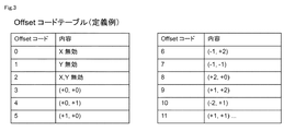
図3は,補正用LUTの圧縮に利用するオフセットコードテーブルの例を示している。また,図4は,補正用LUTを圧縮した圧縮LUTと,その圧縮ビットの構成例を示している。図3及び図4では,補正用LUTの1ピクセル当たりの情報量を,圧縮LUTにおいて16ビット/ピクセルの情報量に圧縮する例を示している。 FIG. 3 shows an example of an offset code table used for compression of the correction LUT. FIG. 4 shows a configuration example of a compressed LUT obtained by compressing the correction LUT and its compressed bits. 3 and 4 show an example in which the information amount per pixel of the correction LUT is compressed to an information amount of 16 bits / pixel in the compression LUT.
図3に示されるように,オフセットコードテーブルは,歪み補正前の座標値と歪み補正後の座標値とのオフセット値(差分値)を,所定のオフセットコードと対応付けて記録している。例えば,本例において,オフセットコードテーブルの内容部分には,X座標とY座標のそれぞれについて,変換前後の座標の整数部の値を比較し,その値のオフセット値(差分値)が情報として記録されている。また,オフセットコードテーブルにおいては,各オフセット値に,所定のオフセットコードが割り当てられている。例えば,オフセットコードは,4bitの情報として設定されている。ただし,オフセットコードのサイズは,4bitに限定されず,適宜最適なサイズに調整できる。また,オフセットコードテーブルの内容部分には,オフセットコードと対応付けて,X座標,Y座標,又はその両方を無効にするための情報を記録することもできる。 As shown in FIG. 3, the offset code table records an offset value (difference value) between the coordinate value before distortion correction and the coordinate value after distortion correction in association with a predetermined offset code. For example, in this example, in the content part of the offset code table, the value of the integer part of the coordinate before and after conversion is compared for each of the X coordinate and the Y coordinate, and the offset value (difference value) of the value is recorded as information. Has been. In the offset code table, a predetermined offset code is assigned to each offset value. For example, the offset code is set as 4-bit information. However, the size of the offset code is not limited to 4 bits, and can be adjusted to an optimal size as appropriate. In addition, information for invalidating the X coordinate, the Y coordinate, or both can be recorded in the content portion of the offset code table in association with the offset code.
図4に示されるように,補正用LUTは,図3に示されたオフセットコードテーブルの値を利用して圧縮され,圧縮LUTへと変換される。つまり,圧縮LUTは,オフセットコードを,当該オフセットコードに対応するオフセット値を参照して圧縮された座標値と対応付けて記録した構成となっている。具体的に説明すると,本実施形態においては,図3に示したオフセットコードテーブルにおいて,歪み補正前の座標値の整数部と歪み補正後の座標値の整数部とのオフセット値に対して,所定のオフセットコードが割り当てられている。このため,図4に示した圧縮LUTでは,オフセットコードが,当該オフセットコードに対応するオフセット値を減算した座標値の小数部(x’frac,y’frac)と対応付けられている。なお,図に示した“frac”は,小数部(fraction part)を意味している。 As shown in FIG. 4, the correction LUT is compressed using the values of the offset code table shown in FIG. 3, and converted into a compressed LUT. That is, the compression LUT has a configuration in which an offset code is recorded in association with a coordinate value compressed by referring to an offset value corresponding to the offset code. More specifically, in the present embodiment, in the offset code table shown in FIG. 3, a predetermined value is used for the offset value between the integer part of the coordinate value before distortion correction and the integer part of the coordinate value after distortion correction. An offset code is assigned. For this reason, in the compression LUT shown in FIG. 4, the offset code is associated with the fractional part (x ′ frac , y ′ frac ) of the coordinate value obtained by subtracting the offset value corresponding to the offset code. Note that “frac” shown in the figure means a fraction part.
補正用LUTから圧縮LUTへの変換方法について,図2から図4を参照してさらに具体的に説明する。 The conversion method from the correction LUT to the compression LUT will be described more specifically with reference to FIGS.
[1] 圧縮前の補正用LUTを見ると,座標値(x,y)=(0,0)を座標値(x’,y’)=(0,0)に変換する部分において,整数部のオフセット値は(+0,+0)である。(+0,+0)のオフセット値は,オフセットコードテーブルにおいて,オフセットコード=3と定義されている。また,(x,y)=(0,0)から(x’,y’)=(0,0)の変換において,小数点以下の値に差は生じていない。従って,圧縮LUTにおいては,(x’frac,y’frac,オフセットコード)=(0,0,3)として記録される。 [1] Looking at the correction LUT before compression, in the part for converting the coordinate value (x, y) = (0, 0) to the coordinate value (x ′, y ′) = (0, 0), the integer part The offset value is (+0, +0). The offset value (+0, +0) is defined as offset code = 3 in the offset code table. In the conversion from (x, y) = (0, 0) to (x ′, y ′) = (0, 0), there is no difference in the values after the decimal point. Therefore, in the compressed LUT, (x ′ frac , y ′ frac , offset code) = (0, 0, 3) is recorded.
[2] 圧縮前の補正用LUTを見ると,座標値(x,y)=(1,0)を座標値(x’,y’)=(1.2,0)に変換する部分において,整数部のオフセット値は(+0,+0)である。(+0,+0)のオフセット値は,オフセットコードテーブルにおいて,オフセットコード=3と定義されている。また,(x,y)=(1,0)から(x’,y’)=(1.2,0)の変換において,小数点以下の値はx座標値にのみ0.2の差が生じており,y座標値には生じていない。従って,圧縮LUTにおいては,(x’frac,y’frac,オフセットコード)=(0.2,0,3)として記録される。 [2] Looking at the correction LUT before compression, in the part for converting the coordinate value (x, y) = (1, 0) to the coordinate value (x ′, y ′) = (1.2, 0), The offset value of the integer part is (+0, +0). The offset value (+0, +0) is defined as offset code = 3 in the offset code table. Further, in the conversion from (x, y) = (1, 0) to (x ′, y ′) = (1.2, 0), the value after the decimal point has a difference of 0.2 only in the x coordinate value. It does not occur in the y coordinate value. Therefore, in the compression LUT, it is recorded as (x ′ frac , y ′ frac , offset code) = (0.2, 0, 3).
[3]圧縮前の補正用LUTを見ると,座標値(x,y)=(2,0)を座標値(x’,y’)=(3.0,1.1)に変換する部分において,整数部のオフセット値は(+1,+1)である。(+1,+1)のオフセット値は,オフセットコードテーブルにおいて,オフセットコード=11と定義されている。また,(x,y)=(2,0)から(x’,y’)=(3.0,1.1)の変換において,小数点以下の値はy座標値にのみ0.1の差が生じており,x座標値には生じていない。従って,圧縮LUTにおいては,(x’frac,y’frac,オフセットコード)=(0.0,0.1,11)として記録される。 [3] Looking at the correction LUT before compression, the portion for converting the coordinate value (x, y) = (2, 0) to the coordinate value (x ′, y ′) = (3.0, 1.1) , The offset value of the integer part is (+1, +1). The offset value (+1, +1) is defined as offset code = 11 in the offset code table. In the conversion from (x, y) = (2, 0) to (x ′, y ′) = (3.0, 1.1), the value after the decimal point is a difference of 0.1 only in the y coordinate value. Has occurred and not in the x-coordinate value. Therefore, in the compressed LUT, (x ′ frac , y ′ frac , offset code) = (0.0, 0.1, 11) is recorded.
上記のように,補正用LUTは,オフセットコードテーブルの値を利用して圧縮されて,圧縮LUTへと変換される。補正用LUTでは,変換前と変換後のそれぞれにについて,x座標とy座標の座標値が,整数部と小数部を含んだまま記録されている。これに対して,圧縮LUTでは,変換前後の座標値の整数部の差が4bitのオフセットコード値で表され,変換後のx座標とy座標の小数部の値のみが,当該オフセットコード値と対応付けて記録されている。従って,圧縮LUTの情報量は,補正用LUTの情報量と比較して,圧倒的に小さくなっているといえる。 As described above, the correction LUT is compressed using the value of the offset code table and converted into a compressed LUT. In the correction LUT, the coordinate values of the x-coordinate and the y-coordinate are recorded including the integer part and the decimal part before and after the conversion. On the other hand, in the compression LUT, the difference between the integer parts of the coordinate values before and after conversion is represented by a 4-bit offset code value, and only the value of the decimal part of the converted x coordinate and y coordinate is the offset code value. Correspondingly recorded. Therefore, it can be said that the information amount of the compression LUT is significantly smaller than the information amount of the correction LUT.
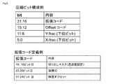
また,図4には,圧縮LUTにおける圧縮ビットの構成例が示されている。圧縮ビットは,例えば,0〜5までの6bit(下位ビット)を,変換後のx座標の小数部のデータとし,6〜11までの6bit(下位ビット)を,変換後のy座標の小数部のデータとし,12〜15までの4bit(上位ビット)を,オフセットコード値としている。このように,合計16bitのデータとして構成できる。つまり,圧縮LUTにおいては,歪み補正に利用する1ピクセル当たりの情報量を,16ビットに圧縮することができる。このように歪み補正に利用するLUTの情報量を圧縮することで,その圧縮によって生じたメモリの余剰空間には,他の処理で利用する情報(例えば,切り出しに関わるマスク情報や,画像ID,輝度調整用の情報)を格納することが可能となる。 FIG. 4 shows a configuration example of compressed bits in the compressed LUT. The compression bit is, for example, 6 bits (lower bits) from 0 to 5 as data of the decimal part of the converted x coordinate, and 6 bits (lower bits) from 6 to 11 are converted to the decimal part of the y coordinate after conversion. 4 bits (upper bits) from 12 to 15 are used as offset code values. In this way, the data can be configured as a total of 16 bits. That is, in the compression LUT, the information amount per pixel used for distortion correction can be compressed to 16 bits. By compressing the amount of information in the LUT used for distortion correction in this way, information used in other processing (for example, mask information related to clipping, image ID, Information for brightness adjustment) can be stored.
なお,本実施形態では,一例として,16ビット/ピクセルの情報例を示した。ただし,圧縮ビットを構成する各ビットフィールド(x座標,y座標,オフセットコード)のサイズや,圧縮ビット全体のサイズについては,アプリケーションごとに最適なサイズの選択を行うことが可能である。 In the present embodiment, an example of information of 16 bits / pixel is shown as an example. However, regarding the size of each bit field (x coordinate, y coordinate, offset code) constituting the compressed bit and the size of the entire compressed bit, it is possible to select an optimum size for each application.
図1に示されるように,上記のようにして作成された圧縮LUT11bは,オフセットコードテーブル11aとともに,補正値記憶部11に記憶される。図1において,補正値記憶部11は,1つの記憶装置(メモリ)によって構築されているように描画されているが,補正値記憶部11は,複数の記憶装置(メモリ)によって構築されていてもよい。このため,オフセットコードテーブル11aと圧縮LUT11bは必ずしも同じ記憶装置内に格納されている必要はなく,物理的には別々の記憶装置内に格納されていてもよい。
As shown in FIG. 1, the compressed LUT 11b created as described above is stored in the correction
LUT展開部12は,補正値記憶部11に記憶されている圧縮LUT11b及びオフセットコードテーブル11aに基づいて,補正用LUT11cする。LUT展開部12は,補正用LUT11cを補正値記憶部11(メモリ)に展開してもよいし,その他の内部メモリに展開してもよいし,外部メモリに展開してもよい。また,LUT展開部12は,補正用LUT11cをラインバッファ又は外部メモリ30に展開することもできる。具体的に説明すると,圧縮LUT11bには,上述したとおり,1ピクセルごとに,x座標の小数部,y座標の小数部,及びオフセットコードが対応付けて記録されている。LUT展開部12は,圧縮LUT11b内のオフセットコードに基づいて,オフセットコードテーブル11aを参照し,当該オフセットコードに対応付けられている座標のオフセット値(座標の整数部)を読み出す。そして,LUT展開部12は,オフセットコードテーブル11aから読み出した座標のオフセット値(整数部)を,x座標の小数部とy座標の小数部に加算する演算処理を行う。これにより,圧縮LUT11bを,オフセットコードテーブル11aの値に基づいて解凍し,補正用LUT11cを生成することができる。
The
必要な画像入力が終わった時点で,制御部60から歪み補正処理のスタートが指示され,LUT展開部12は,補正値記憶部11から圧縮LUT11bを読み出してこれを解凍し,補正用LUT11cを展開するとともに,この補正用LUT11cの値を座標変換部13に入力する。座標変換部13は,LUT展開部12によって生成された補正用LUT11cを参照して,ラインバッファ30(又は外部メモリ)に格納されている画像データに対して,1ピクセル単位で,歪み補正処理を実行する。つまり,座標変換部13は,補正用LUT11cを参照して,補正前の入力画像の各ピクセルの座標値を,歪み補正後の座標値に変換する演算を行う。座標変換部13は,各ピクセルについて歪み補正処理が完了した段階で,その補正後の座標の情報と共にピクセルの情報をフィルタ部40に送出する。
When necessary image input is completed, the
また,座標変換部13は,画像データの歪み補正処理において,歪み補正式の演算を行うこともできる。具体的には,座標変換部13では,下記(1)(2)の式の演算を行う。
(1)xd=歪み補正式で求められたx値+展開された補正用LUTのx値
(2)yd=歪み補正式で求められたy値+展開された補正用LUTのy値
ここでの歪み補正式としては,公知の補正式を用いることができる。例えば,歪み補正式としては,公知のBrown-Conradyモデルを利用すればよい。より具体的に説明すると,座標変換部13には,下記の数式を演算するためのアルゴリズムが実装される。
In addition, the coordinate
(1) x d = x value obtained by the distortion correction formula + x value of the developed correction LUT (2) y d = y value obtained by the distortion correction formula + y value of the developed correction LUT As the distortion correction formula here, a known correction formula can be used. For example, a known Brown-Conrady model may be used as a distortion correction formula. More specifically, the coordinate

上記の式に基づく演算が終了すると,座標変換部13は,補正後の座標の情報とともに,ピクセルの情報をフィルタ部40に入力する。フィルタ部40では,上述したとおり,補正後の座標値を参照しながら,テクスチャマッピングで行われるフィルタ手法と同様にバイリニアフィルタなどによるピクセルの補間処理を行う。その後,フィルタ部40で演算された結果は,画像出力部50を通して,ディスプレイ又は出力画像データを格納するためのメモリに格納される。また,同様の演算を画像出力解像度分行い,歪み後の画像が生成される。
When the calculation based on the above equation is completed, the coordinate
なお,本願の図2及び図4に示した例では,補正用LUTにおいて,変換前の座標値に歪み補正式の適用していないが,この変換前の座標値に,上記歪み補正式を組み合わせることも可能である。その場合,補正用LUTにおける変換前の座標値として,上記歪み補正式を適用した(xd,yd)の値が格納され,変換後の座標値として,(xd’,yd’)が格納されることとなり。このような場合でも,その後の圧縮LUTの生成やこれの解凍処理は,上述したものと同様に行うことができる。 In the example shown in FIG. 2 and FIG. 4 of the present application, the distortion correction formula is not applied to the coordinate value before conversion in the correction LUT, but the distortion correction formula is combined with the coordinate value before conversion. It is also possible. In that case, the value of (x d , y d ) to which the above distortion correction formula is applied is stored as the coordinate value before conversion in the correction LUT, and (x d ′, y d ′) is stored as the coordinate value after conversion. Will be stored. Even in such a case, the subsequent generation of the compression LUT and the decompression process thereof can be performed in the same manner as described above.
続いて,図5を参照して,画像処理装置100における制御部60の処理フローについて説明する。制御部60は,まず,画像データの入力開始前に,圧縮LUTを作成する前処理を行う(ステップS1)。画像処理装置100にカメラ入力デバイス等の入力装置200が接続されると,制御部60は,入力装置200が備える光学レンズの歪みを,チェッカボードによる画像処理や3D計測によって検出し,歪みマップを作成する。光学レンズの歪みマップとは,歪みのないフラットな画像に対して,光学レンズから入力された画像がどの領域でどの程度歪みを生じているのかを表したマップである。他方,画像処理装置100に透過型のヘッドアップディスプレイ等の出力装置300が接続されると,制御部60は,ヘッドアップディスプレイ上の歪みを検出し,ディスプレイの歪みマップを作成してもよい。ディスプレイの歪みマップとは,歪みのないフラットな画像に対して,ヘッドアップディスプレイの表示画面がどの領域でどの程度歪みを生じているのかを表したマップである。このような意味において,画像処理装置100の制御部60は,入力装置200や出力装置300の歪み検出部を有するといえる。また,制御部60は,歪みマップに基づいて,圧縮前の補正用LUTを作成する。また,補正値記憶部11には,上述したオフセットコードテーブルが既に作成されて記憶されている。そこで,制御部60は,既成のオフセットコードテーブルの値に基づいて,補正用LUTを圧縮した圧縮LUTを作成し,オフセットコードテーブルと共に補正値記憶部11に記憶する。補正用LUTから圧縮LUTを作成する方法は,上述したとおりである。
Next, a processing flow of the
その後,画像処理装置100に対して,画像データの入力が開始される(ステップS2)。画像データが入力されると処理に必要なピクセル画像を準備した後に,出力ピクセル分のループに入る。ループ内では,まず,入力されたピクセルの座標に応じて,対応する座標変換後の値を圧縮LUTから補正用LUTに展開し,この補正用LUTに基づいて座標変換を実施する(ステップ3)。その後,ラインバッファ又は外部メモリ30から必要な画像データを読み込み,出力ピクセル分を準備し,フィルタ部40に入力を行う(ステップS4)。その後,フィルタ部40でバイリニアフィルタリング等のフィルタ処理が行われた後,このフィルタ処理後の画像を画像出力部50に送り,この画像出力部50を通じて,歪み補正後の画像データを外部メモリに格納したり,ディスプレイに表示したりする処理を行う(ステップS5)。同様の処理を画像出力解像度分ループさせて行い,歪み後の画像を生成する。
Thereafter, input of image data is started to the image processing apparatus 100 (step S2). When image data is input, a pixel image necessary for processing is prepared, and then a loop for output pixels is entered. In the loop, first, the corresponding coordinate-converted value is expanded from the compression LUT to the correction LUT according to the coordinates of the input pixel, and coordinate conversion is performed based on the correction LUT (step 3). . Thereafter, necessary image data is read from the line buffer or the external memory 30 to prepare output pixels and input to the filter unit 40 (step S4). Thereafter, after filter processing such as bilinear filtering is performed in the
続いて,図6を参照して,圧縮テーブルの拡張内容の例について説明する。図4を用いて説明したように,圧縮テーブルを構成する1ピクセル当たりの圧縮ビットは,0〜5までの下位6bitに変換後のx座標の小数部を割り当て,6〜11までの下位6bitに変換後のy座標の小数部を割り当て,12〜15までの上位4bitにオフセットコード値を割り当てて,合計16bitで構成されている。このように圧縮ビットは,情報量の小さいデータであるあるため,これを格納するメモリには余剰空間が生じる。従って,圧縮ビットを拡張して,その他の有用な情報を格納することができる。 Next, an example of the expanded contents of the compression table will be described with reference to FIG. As described with reference to FIG. 4, the compression bits per pixel constituting the compression table allocate the decimal part of the x coordinate after conversion to the lower 6 bits from 0 to 5, and to the lower 6 bits from 6 to 11 The decimal part of the converted y-coordinate is assigned, and the offset code value is assigned to the upper 4 bits from 12 to 15, and the total is 16 bits. As described above, since the compressed bit is data with a small amount of information, a surplus space is generated in the memory for storing the compressed bit. Therefore, the compression bit can be expanded to store other useful information.
例えば,図6の上図に示されるように,圧縮ビットを0〜31の32bitのデータに拡張し,16〜31までの16bitに拡張コードを割り当てる。拡張コードは,ピクセルごとの画像処理に利用される処理情報を指示するものであり,拡張コードの定義例は図6の下図に示されている。例えば,拡張コードによって指示される処理情報としては,切り出しに関わるマスク情報(1ピクセルごとに出力の有無を制御可能)や,画像ID(ステッチング用。複数入力画像を組み合わせて表示させる場合,領域ごとにどの入力画像を使うか選択可能),あるいは輝度調整用の情報(車載用途などで時間帯やライトのON/OFFの状況に応じ,色味や輝度を変えることで可視性をあげることが可能)などを挙げることができる。例えば,図6の下図に示されるように,16〜19bitに切り出しマスク(透過度設定)の処理情報を割り当て,20〜23bitに画像IDを割り当て,24〜31に輝度オフセットを割り当てることができる。このように,ピクセル単位での処理に有用な処理情報を圧縮ビットの拡張部分に割り当てることで,画像描画処理の効率化及び高速化を実現できる。 For example, as shown in the upper diagram of FIG. 6, the compression bit is expanded to 32-bit data of 0 to 31, and an expansion code is assigned to 16 bits of 16 to 31. The extension code indicates processing information used for image processing for each pixel, and an example of definition of the extension code is shown in the lower diagram of FIG. For example, processing information instructed by the extension code includes mask information related to clipping (the presence or absence of output can be controlled for each pixel) and image ID (for stitching. When displaying multiple input images in combination, Each input image can be selected), or brightness adjustment information (in-vehicle use, etc., depending on the time zone and light ON / OFF status, visibility can be increased by changing the color and brightness Possible). For example, as shown in the lower diagram of FIG. 6, processing information of a clipping mask (transparency setting) can be assigned to 16 to 19 bits, an image ID can be assigned to 20 to 23 bits, and a luminance offset can be assigned to 24 to 31. As described above, by assigning processing information useful for processing in units of pixels to the extended portion of the compressed bit, it is possible to realize the efficiency and speed of the image drawing processing.
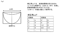
続いて,図7を参照して,補正用LUTの他の圧縮方法について説明する。図7には,歪み補正後の画像の形状が左右対称である場合に,この補正用LUTの情報量を半分にすることができる例が示されている。図7に示されるように,補正後の画像形状が左右対称である場合,例えば,補正用LUTは,変換後画像の左半分のみ(x=0から画像中心(width/2)まで)作成しておけば,変換後画像の右半分は省略できる。つまり,変換後の右半分については,(width−x)という単純な演算を行うことで,その演算値を右半分のx値として使用することができる。なお,図7では,変換後画像が左右対称である場合を説明したが,変換後画像が上下対称である場合も同じようにして,補正用LUTの情報量を半分にすることができる。 Next, another compression method of the correction LUT will be described with reference to FIG. FIG. 7 shows an example in which the information amount of the correction LUT can be halved when the shape of the image after distortion correction is symmetrical. As shown in FIG. 7, when the image shape after correction is symmetrical, for example, the correction LUT is created only from the left half of the converted image (from x = 0 to the image center (width / 2)). If so, the right half of the converted image can be omitted. That is, for the right half after conversion, a simple calculation of (width-x) can be performed, and the calculated value can be used as the x value of the right half. Although FIG. 7 illustrates the case where the converted image is bilaterally symmetric, the amount of information in the correction LUT can be halved in the same manner when the converted image is vertically symmetric.
以上,本願明細書では,本発明の内容を表現するために,図面を参照しながら本発明の実施形態の説明を行った。ただし,本発明は,上記実施形態に限定されるものではなく,本願明細書に記載された事項に基づいて当業者が自明な変更形態や改良形態を包含するものである。 As mentioned above, in this specification, in order to express the content of this invention, embodiment of this invention was described, referring drawings. However, the present invention is not limited to the above-described embodiments, but includes modifications and improvements obvious to those skilled in the art based on the matters described in the present specification.
本発明は,画像データの歪みを補正するための機能を有する画像処理装置及びプログラムに関する。本発明に係る装置及びプログラムは,画像処理のためのコンピュータや,デジタルカメラ,あるいはヘッドアップディスプレイ等に適用することができる。従って,本発明はコンピュータ関連産業や,ゲーム関連産業,医療関連産業,車載関連産業において好適に利用しうる。 The present invention relates to an image processing apparatus and a program having a function for correcting distortion of image data. The apparatus and program according to the present invention can be applied to a computer for image processing, a digital camera, a head-up display, or the like. Therefore, the present invention can be suitably used in computer related industries, game related industries, medical related industries, and in-vehicle related industries.
10…画像補正手段 11…補正値記憶部
11a…オフセットコードテーブル 11b…圧縮LUT
11c…補正用LUT 12…LUT展開部
13…座標変換部 20…画像データ入力部
30…ラインバッファ又は外部メモリ 40…フィルタ部
50…画像出力部 60…制御部
100…画像処理装置 200…入力装置
300…出力装置
DESCRIPTION OF
11c ... LUT for
Claims (6)
前記画像補正手段(10)は,
補正値記憶部(11)と,ルックアップテーブル(LUT)展開部(12)と,座標変換部(13)とを有するものであり,
前記補正値記憶部(11)は,
歪み補正前の座標値と歪み補正後の座標値とのオフセット値を,所定のオフセットコードと対応付けたオフセットコードテーブル(11a)と,
前記オフセットコードを,当該オフセットコードに対応するオフセット値を参照して圧縮された座標値と対応付けた圧縮LUT(11b)と,を記憶しており,
前記LUT展開部(12)は,
前記オフセットコードテーブル(11a)と前記圧縮LUT(11b)とに基づいて,歪み補正前の座標値と歪み補正後の座標値とを対応付けた補正用LUT(11c)を生成し,
前記座標変換部(13)は,
前記補正用LUT(11c)に基づいて,前記画像データの座標値を補正する
画像処理装置。 An image processing apparatus comprising image correction means (10) for correcting distortion of image data,
The image correction means (10)
A correction value storage unit (11), a lookup table (LUT) development unit (12), and a coordinate conversion unit (13);
The correction value storage unit (11)
An offset code table (11a) in which an offset value between a coordinate value before distortion correction and a coordinate value after distortion correction is associated with a predetermined offset code;
A compressed LUT (11b) in which the offset code is associated with a coordinate value compressed with reference to an offset value corresponding to the offset code;
The LUT expansion unit (12)
Based on the offset code table (11a) and the compression LUT (11b), a correction LUT (11c) in which the coordinate value before distortion correction and the coordinate value after distortion correction are associated is generated,
The coordinate conversion unit (13)
An image processing apparatus for correcting a coordinate value of the image data based on the correction LUT (11c).
前記圧縮LUT(11b)は,前記オフセットコードを,当該オフセットコードに対応するオフセット値を減算した座標値の小数部と対応付けたものである
請求項1に記載の画像処理装置。 The offset code table (11a) associates an offset value between the integer part of the coordinate value before distortion correction and the integer part of the coordinate value after distortion correction with a predetermined offset code,
The image processing apparatus according to claim 1, wherein the compression LUT (11b) associates the offset code with a fractional part of coordinate values obtained by subtracting an offset value corresponding to the offset code.
請求項1又は請求項2に記載の画像処理装置。 The compressed LUT (11b) is associated with an extended code indicating processing information used for image processing at the coordinate value in addition to the compressed coordinate value and the offset code. The image processing apparatus according to claim 2.
請求項1から請求項3のいずれかに記載の画像処理装置。 When the image data after distortion correction is vertically symmetric or horizontally symmetric, the correction LUT (11c) holds coordinate values of only one of the upper and lower sides or only one of the left and right sides with the symmetry axis as a boundary. 4. The image processing device according to any one of 3.
請求項1から請求項4のいずれかに記載の画像処理装置。 The coordinate conversion unit (13) is obtained by applying a predetermined distortion correction formula to the coordinate values after distortion correction held in the correction LUT (11c) and the coordinate values of the image data. The image processing device according to claim 1, wherein the coordinate value of the image data is corrected based on the coordinate value.
前記画像補正手段(10)は,
補正値記憶部(11)と,LUT展開部(12)と,座標変換部(13)とを有するものであり,
前記補正値記憶部(11)は,
歪み補正前の座標値と歪み補正後の座標値とのオフセット値を,所定のオフセットコードと対応付けたオフセットコードテーブル(11a)と,
前記オフセットコードを,当該オフセットコードに対応するオフセット値を参照して圧縮された座標値と対応付けた圧縮LUT(11b)と,を記憶しており,
前記LUT展開部(12)は,
前記オフセットコードテーブル(11a)と前記圧縮LUT(11b)とに基づいて,歪み補正前の座標値と歪み補正後の座標値とを対応付けた補正用LUT(11c)を生成し,
前記座標変換部(13)は,
前記補正用LUT(11c)に基づいて,前記画像データの座標値を補正する
プログラム。 A program for causing a computer to function as an image processing apparatus including image correction means (10) for correcting distortion of image data,
The image correction means (10)
A correction value storage unit (11), an LUT expansion unit (12), and a coordinate conversion unit (13);
The correction value storage unit (11)
An offset code table (11a) in which an offset value between a coordinate value before distortion correction and a coordinate value after distortion correction is associated with a predetermined offset code;
A compressed LUT (11b) in which the offset code is associated with a coordinate value compressed with reference to an offset value corresponding to the offset code;
The LUT expansion unit (12)
Based on the offset code table (11a) and the compression LUT (11b), a correction LUT (11c) in which the coordinate value before distortion correction and the coordinate value after distortion correction are associated is generated,
The coordinate conversion unit (13)
A program for correcting the coordinate value of the image data based on the correction LUT (11c).
Priority Applications (1)
| Application Number | Priority Date | Filing Date | Title |
|---|---|---|---|
| JP2015134419A JP2017016511A (en) | 2015-07-03 | 2015-07-03 | Distortion correction image processor and program |
Applications Claiming Priority (1)
| Application Number | Priority Date | Filing Date | Title |
|---|---|---|---|
| JP2015134419A JP2017016511A (en) | 2015-07-03 | 2015-07-03 | Distortion correction image processor and program |
Publications (1)
| Publication Number | Publication Date |
|---|---|
| JP2017016511A true JP2017016511A (en) | 2017-01-19 |
Family
ID=57830849
Family Applications (1)
| Application Number | Title | Priority Date | Filing Date |
|---|---|---|---|
| JP2015134419A Pending JP2017016511A (en) | 2015-07-03 | 2015-07-03 | Distortion correction image processor and program |
Country Status (1)
| Country | Link |
|---|---|
| JP (1) | JP2017016511A (en) |
Cited By (2)
| Publication number | Priority date | Publication date | Assignee | Title |
|---|---|---|---|---|
| CN111130554A (en) * | 2019-12-09 | 2020-05-08 | 深圳市兴之佳科技有限公司 | File compression method and device, electronic equipment and readable storage medium |
| US11024015B2 (en) | 2019-03-14 | 2021-06-01 | Kabushiki Kaisha Toshiba | Image processing apparatus and distortion correction coefficient calculation method |
-
2015
- 2015-07-03 JP JP2015134419A patent/JP2017016511A/en active Pending
Cited By (3)
| Publication number | Priority date | Publication date | Assignee | Title |
|---|---|---|---|---|
| US11024015B2 (en) | 2019-03-14 | 2021-06-01 | Kabushiki Kaisha Toshiba | Image processing apparatus and distortion correction coefficient calculation method |
| CN111130554A (en) * | 2019-12-09 | 2020-05-08 | 深圳市兴之佳科技有限公司 | File compression method and device, electronic equipment and readable storage medium |
| CN111130554B (en) * | 2019-12-09 | 2023-08-04 | 深圳市兴之佳科技有限公司 | File compression method and device, electronic equipment and readable storage medium |
Similar Documents
| Publication | Publication Date | Title |
|---|---|---|
| KR101785027B1 (en) | Image distortion compensation display device and image distortion compensation method using the same | |
| JP4018601B2 (en) | Digital image scaling method for embedded system | |
| US8830402B2 (en) | Image processing circuit and method thereof | |
| US11908107B2 (en) | Method and apparatus for presenting image for virtual reality device, device and non-transitory computer-readable storage medium | |
| TW200937346A (en) | Image distortion correction | |
| US20190027120A1 (en) | Method of and data processing system for providing an output surface | |
| JP3833212B2 (en) | Image processing apparatus, image processing program, and readable recording medium | |
| US20190005622A1 (en) | Image processing apparatus, control method thereof, and storage medium | |
| JP2017016511A (en) | Distortion correction image processor and program | |
| JP2013243610A (en) | Image data transmission apparatus, image data reception apparatus, image data transmission system, image data transmission method, image data reception method, transmission image data, and program | |
| US11954765B2 (en) | Applying random patches to pixel block of an image utilizing different weights | |
| US10553004B2 (en) | Method and apparatus for processing image and recording medium storing program therefor | |
| JP2008116812A (en) | Display apparatus, projector, and display method | |
| US20200184693A1 (en) | Computer program, image processing method, and image processing apparatus | |
| JP6326914B2 (en) | Interpolation apparatus and interpolation method | |
| JP2015128263A (en) | Image processing system, image processing method, program for image processing and imaging apparatus | |
| WO2023037447A1 (en) | Image processing apparatus, method, and program | |
| JP2012019315A (en) | Image processor and image processing method | |
| JP5085589B2 (en) | Image processing apparatus and method | |
| JP2018133772A (en) | Image processing device and image processing method | |
| JP2004240910A (en) | Image processor and image processing method | |
| JP5669199B2 (en) | Image drawing apparatus, image drawing method, and program | |
| CN115617288A (en) | Screen recording method and device, storage medium and electronic equipment | |
| JP2018106238A (en) | Image processing apparatus, image processing method and program | |
| JP5761386B2 (en) | Image processing apparatus, image processing method, and image processing program |