JP5997882B2 - Projector and projector control method - Google Patents
Projector and projector control method Download PDFInfo
- Publication number
- JP5997882B2 JP5997882B2 JP2011159628A JP2011159628A JP5997882B2 JP 5997882 B2 JP5997882 B2 JP 5997882B2 JP 2011159628 A JP2011159628 A JP 2011159628A JP 2011159628 A JP2011159628 A JP 2011159628A JP 5997882 B2 JP5997882 B2 JP 5997882B2
- Authority
- JP
- Japan
- Prior art keywords
- image
- deformation rate
- osd
- image data
- composite image
- Prior art date
- Legal status (The legal status is an assumption and is not a legal conclusion. Google has not performed a legal analysis and makes no representation as to the accuracy of the status listed.)
- Expired - Fee Related
Links
- 238000000034 method Methods 0.000 title claims description 37
- 239000002131 composite material Substances 0.000 claims description 47
- 238000006243 chemical reaction Methods 0.000 claims description 44
- 238000004364 calculation method Methods 0.000 claims description 15
- 230000003287 optical effect Effects 0.000 claims description 10
- 238000003860 storage Methods 0.000 claims description 10
- 230000005484 gravity Effects 0.000 claims description 5
- 238000013500 data storage Methods 0.000 claims 1
- 230000004048 modification Effects 0.000 description 16
- 238000012986 modification Methods 0.000 description 16
- 239000004973 liquid crystal related substance Substances 0.000 description 15
- 238000010586 diagram Methods 0.000 description 13
- 230000009466 transformation Effects 0.000 description 11
- 230000006870 function Effects 0.000 description 10
- 238000005286 illumination Methods 0.000 description 6
- 239000000203 mixture Substances 0.000 description 4
- 238000003384 imaging method Methods 0.000 description 3
- QSHDDOUJBYECFT-UHFFFAOYSA-N mercury Chemical compound [Hg] QSHDDOUJBYECFT-UHFFFAOYSA-N 0.000 description 2
- 229910052753 mercury Inorganic materials 0.000 description 2
- 230000001133 acceleration Effects 0.000 description 1
- 230000007423 decrease Effects 0.000 description 1
- 230000003247 decreasing effect Effects 0.000 description 1
- 238000009826 distribution Methods 0.000 description 1
- 239000000284 extract Substances 0.000 description 1
- 238000004519 manufacturing process Methods 0.000 description 1
- 239000011159 matrix material Substances 0.000 description 1
- 238000002834 transmittance Methods 0.000 description 1
Images


Classifications
-
- G—PHYSICS
- G09—EDUCATION; CRYPTOGRAPHY; DISPLAY; ADVERTISING; SEALS
- G09G—ARRANGEMENTS OR CIRCUITS FOR CONTROL OF INDICATING DEVICES USING STATIC MEANS TO PRESENT VARIABLE INFORMATION
- G09G3/00—Control arrangements or circuits, of interest only in connection with visual indicators other than cathode-ray tubes
- G09G3/001—Control arrangements or circuits, of interest only in connection with visual indicators other than cathode-ray tubes using specific devices not provided for in groups G09G3/02 - G09G3/36, e.g. using an intermediate record carrier such as a film slide; Projection systems; Display of non-alphanumerical information, solely or in combination with alphanumerical information, e.g. digital display on projected diapositive as background
- G09G3/002—Control arrangements or circuits, of interest only in connection with visual indicators other than cathode-ray tubes using specific devices not provided for in groups G09G3/02 - G09G3/36, e.g. using an intermediate record carrier such as a film slide; Projection systems; Display of non-alphanumerical information, solely or in combination with alphanumerical information, e.g. digital display on projected diapositive as background to project the image of a two-dimensional display, such as an array of light emitting or modulating elements or a CRT
-
- G—PHYSICS
- G09—EDUCATION; CRYPTOGRAPHY; DISPLAY; ADVERTISING; SEALS
- G09G—ARRANGEMENTS OR CIRCUITS FOR CONTROL OF INDICATING DEVICES USING STATIC MEANS TO PRESENT VARIABLE INFORMATION
- G09G5/00—Control arrangements or circuits for visual indicators common to cathode-ray tube indicators and other visual indicators
-
- H—ELECTRICITY
- H04—ELECTRIC COMMUNICATION TECHNIQUE
- H04N—PICTORIAL COMMUNICATION, e.g. TELEVISION
- H04N9/00—Details of colour television systems
- H04N9/12—Picture reproducers
- H04N9/31—Projection devices for colour picture display, e.g. using electronic spatial light modulators [ESLM]
- H04N9/3179—Video signal processing therefor
- H04N9/3185—Geometric adjustment, e.g. keystone or convergence
-
- G—PHYSICS
- G09—EDUCATION; CRYPTOGRAPHY; DISPLAY; ADVERTISING; SEALS
- G09G—ARRANGEMENTS OR CIRCUITS FOR CONTROL OF INDICATING DEVICES USING STATIC MEANS TO PRESENT VARIABLE INFORMATION
- G09G2320/00—Control of display operating conditions
- G09G2320/06—Adjustment of display parameters
- G09G2320/0693—Calibration of display systems
-
- G—PHYSICS
- G09—EDUCATION; CRYPTOGRAPHY; DISPLAY; ADVERTISING; SEALS
- G09G—ARRANGEMENTS OR CIRCUITS FOR CONTROL OF INDICATING DEVICES USING STATIC MEANS TO PRESENT VARIABLE INFORMATION
- G09G2320/00—Control of display operating conditions
- G09G2320/08—Arrangements within a display terminal for setting, manually or automatically, display parameters of the display terminal
-
- H—ELECTRICITY
- H04—ELECTRIC COMMUNICATION TECHNIQUE
- H04N—PICTORIAL COMMUNICATION, e.g. TELEVISION
- H04N21/00—Selective content distribution, e.g. interactive television or video on demand [VOD]
- H04N21/40—Client devices specifically adapted for the reception of or interaction with content, e.g. set-top-box [STB]; Operations thereof
- H04N21/43—Processing of content or additional data, e.g. demultiplexing additional data from a digital video stream; Elementary client operations, e.g. monitoring of home network or synchronising decoder's clock; Client middleware
- H04N21/431—Generation of visual interfaces for content selection or interaction; Content or additional data rendering
-
- H—ELECTRICITY
- H04—ELECTRIC COMMUNICATION TECHNIQUE
- H04N—PICTORIAL COMMUNICATION, e.g. TELEVISION
- H04N21/00—Selective content distribution, e.g. interactive television or video on demand [VOD]
- H04N21/40—Client devices specifically adapted for the reception of or interaction with content, e.g. set-top-box [STB]; Operations thereof
- H04N21/47—End-user applications
- H04N21/485—End-user interface for client configuration
-
- H—ELECTRICITY
- H04—ELECTRIC COMMUNICATION TECHNIQUE
- H04N—PICTORIAL COMMUNICATION, e.g. TELEVISION
- H04N9/00—Details of colour television systems
- H04N9/12—Picture reproducers
- H04N9/31—Projection devices for colour picture display, e.g. using electronic spatial light modulators [ESLM]
- H04N9/3191—Testing thereof
- H04N9/3194—Testing thereof including sensor feedback
-
- H—ELECTRICITY
- H04—ELECTRIC COMMUNICATION TECHNIQUE
- H04N—PICTORIAL COMMUNICATION, e.g. TELEVISION
- H04N9/00—Details of colour television systems
- H04N9/12—Picture reproducers
- H04N9/31—Projection devices for colour picture display, e.g. using electronic spatial light modulators [ESLM]
- H04N9/3197—Projection devices for colour picture display, e.g. using electronic spatial light modulators [ESLM] using light modulating optical valves
Description
本発明は、プロジェクター及びプロジェクターの制御方法に関する。 The present invention relates to a projector and a projector control method.
プロジェクターがスクリーンに対して水平方向又は垂直方向に傾きを有して設置されると、スクリーンに投写される画像には歪み(台形歪み)が生じる。そこで、プロジェクターが、スクリーンに投写された画像の台形歪みと逆の台形歪みを有する画像を液晶パネル等のライトバルブに表示させることにより、スクリーンに表示される画像の台形歪みを補正する技術が知られている。特許文献1には、プロジェクターがOSD(On Screen Display)画像を投写画面に重ねてスクリーンに表示する場合に、台形歪みの補正が少ない投写画面上の位置にOSD画像を表示する台形歪み補正装置が記載されている。
When the projector is installed with an inclination in the horizontal direction or the vertical direction with respect to the screen, distortion (trapezoidal distortion) occurs in the image projected on the screen. Therefore, a technique is known in which a projector corrects the trapezoidal distortion of an image displayed on the screen by displaying an image having a trapezoidal distortion opposite to the trapezoidal distortion of the image projected on the screen on a light valve such as a liquid crystal panel. It has been.
特許文献1に記載の台形歪み補正装置においては、台形歪み補正で最も補正の少ない投写画面上の位置が変わると、OSD画像が表示される位置も変わる。また、投写画面の台形歪み補正後にOSD画像が重ね合わされていることから、OSD画像には台形歪み補正は行われず、OSD画像は歪んで投写される。
これに対し本発明は、画像データに対して補正処理が行われる場合において、ある画像に重ねて表示される画像の視認性を向上させる技術を提供する。
In the trapezoidal distortion correction apparatus described in
On the other hand, the present invention provides a technique for improving the visibility of an image displayed superimposed on a certain image when correction processing is performed on the image data.
上述の課題を解決するため、本発明は、第1画像を示す第1画像データを記憶した記憶手段と、前記第1画像データに対して補正処理を行った場合の、前記第1画像において設定された基準点における第1変形率を算出する変形率算出手段と、前記変形率算出手段によって算出された第1変形率に基づいて、前記第1画像の第2変形率を決定する変形率決定手段と、第2画像データにより示される第2画像と、前記変形率決定手段により決定された第2変形率に基づいてサイズが変更された前記第1画像とを合成した合成画像を示す合成画像データを生成する合成画像生成手段と、前記合成画像生成手段により生成された合成画像データに、前記補正処理を行う補正手段と、前記補正処理が行われた前記合成画像データに基づいて前記合成画像を投写する投写手段とを有するプロジェクターを提供する。このプロジェクターによれば、画像データに対して補正処理が行われる場合において、第1変形率によらず第2変形率が一定である場合と比較して、第2画像に重ねて表示される第1画像の視認性を向上させることができる。 In order to solve the above-described problem, the present invention provides a storage unit that stores first image data indicating a first image, and a setting in the first image when correction processing is performed on the first image data. A deformation rate calculating means for calculating a first deformation rate at the determined reference point, and a deformation rate determination for determining a second deformation rate of the first image based on the first deformation rate calculated by the deformation rate calculating means. A composite image showing a composite image obtained by combining the second image indicated by the second image data and the first image whose size has been changed based on the second deformation rate determined by the deformation rate determination means Composite image generation means for generating data, correction means for performing the correction process on the composite image data generated by the composite image generation means, and the composite image based on the composite image data subjected to the correction process. Providing a projector and a projection means for projecting a. According to this projector, when the correction process is performed on the image data, the second image is displayed so as to be superimposed on the second image as compared with the case where the second deformation rate is constant regardless of the first deformation rate. The visibility of one image can be improved.
また、別の好ましい態様において、前記補正処理は、座標変換係数を用いた座標変換処理を含み、前記座標変換係数を取得する変換係数取得手段を備え、前記変形率算出手段は、前記変換係数取得手段により取得された前記座標変換係数に基づいて、前記第1変形率を算出することを特徴とする。このプロジェクターによれば、画像データに対して座標変換処理を含む補正処理が行われる場合において、第2画像に重ねて表示される第1画像の視認性を向上させることができる。 In another preferable aspect, the correction process includes a coordinate conversion process using a coordinate conversion coefficient, and includes conversion coefficient acquisition means for acquiring the coordinate conversion coefficient, and the deformation rate calculation means includes the conversion coefficient acquisition. The first deformation rate is calculated based on the coordinate conversion coefficient acquired by the means. According to this projector, when the correction process including the coordinate conversion process is performed on the image data, it is possible to improve the visibility of the first image displayed so as to be superimposed on the second image.
また、別の好ましい態様において、前記第1画像においては複数の基準点が設定されており、前記変形率算出手段は、前記複数の基準点について前記第1変形率を算出し、前記変形率決定手段は、前記複数の基準点について算出された前記第1変形率の代表値に基づいて、前記第2変形率を決定することを特徴とする。このプロジェクターによれば、基準点が単一のときと比べて、第2画像に重ねて表示される第1画像の視認性を向上させることができる。 In another preferred embodiment, a plurality of reference points are set in the first image, and the deformation rate calculating means calculates the first deformation rate for the plurality of reference points, and determines the deformation rate. The means determines the second deformation rate based on a representative value of the first deformation rate calculated for the plurality of reference points. According to this projector, the visibility of the first image displayed so as to be superimposed on the second image can be improved compared to when the reference point is single.
また、別の好ましい態様において、前記記憶手段は複数の第1画像データを記憶し、前記基準点は前記複数の第1画像毎に設定されていることを特徴とする。このプロジェクターによれば、第1画像が複数あるとき、各第1画像に応じて、その第1画像の視認性を向上させることができる。 In another preferred aspect, the storage means stores a plurality of first image data, and the reference point is set for each of the plurality of first images. According to this projector, when there are a plurality of first images, the visibility of the first image can be improved according to each first image.
また、別の好ましい態様において、前記第1画像はOSD画像であることを特徴とする。このプロジェクターによれば、画像データに対して補正処理が行われる場合において、第1変形率によらず第2変形率が一定である場合と比較して、第2画像に重ねて表示されるOSD画像の視認性を向上させることができる。 In another preferred embodiment, the first image is an OSD image. According to this projector, when the correction process is performed on the image data, the OSD displayed to be superimposed on the second image is compared with the case where the second deformation rate is constant regardless of the first deformation rate. The visibility of the image can be improved.
また、本発明は、第1画像を示す第1画像データに対して補正処理を行った場合の、前記第1画像において設定された基準点における第1変形率を算出する工程と、前記第1変形率に基づいて、前記第1画像の第2変形率を決定する工程と、第2画像データにより示される第2画像と、前記第2変形率に基づいてサイズが変更された前記第1画像とを合成した合成画像を示す合成画像データを生成する工程と、前記合成画像データに、前記補正処理を行う工程とを有するプロジェクターの制御方法を提供する。このプロジェクターの制御方法によれば、画像データに対して補正処理が行われる場合において、第1変形率によらず第2変形率が一定である場合と比較して、第2画像に重ねて表示される第1画像の視認性を向上させることができる。 The present invention also includes a step of calculating a first deformation rate at a reference point set in the first image when correction processing is performed on the first image data representing the first image; A step of determining a second deformation rate of the first image based on a deformation rate, a second image indicated by second image data, and the first image having a size changed based on the second deformation rate A control method for a projector is provided that includes a step of generating composite image data indicating a composite image obtained by combining the above and a step of performing the correction process on the composite image data. According to this projector control method, when the correction process is performed on the image data, the second deformation rate is displayed so as to be superimposed on the second image as compared with the case where the second deformation rate is constant regardless of the first deformation rate. The visibility of the first image to be performed can be improved.
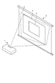
図1は、本発明の一実施形態に係るプロジェクター1の動作概要の説明図である。プロジェクター1は、入力された映像信号に応じた画像(以下「主画像」(第2画像の一例))という)をスクリーンに投写する装置である。スクリーン2は、プロジェクター1から投写される画像を映し出す平面である。プロジェクター1の投写軸がスクリーン2に対して理想的な状態から傾いている場合、スクリーン2に映し出される画像3は歪んだものとなる。以下この歪みを「台形歪み」という。プロジェクター1は、台形歪みを補正し、補正後の画像4を投写する機能を有する。台形歪みを補正する処理を、「台形歪み補正」(補正処理の一例)という。また、プロジェクター1は、画像の明るさ、位置及び台形歪み補正などのパラメーターを調整する機能を有する。これらのパラメーターの調整に用いられるユーザーインターフェースは、スクリーン2に投写されるOSD画像5(第1画像の一例)により提供される。OSD画像5は主画像に重ねて表示される。台形歪み補正は、主画像にOSD画像5を重ねた合成画像に対して行われる。
FIG. 1 is an explanatory diagram of an outline of the operation of the
図2は、プロジェクター1の内部構成を示すブロック図である。プロジェクター1は、CPU(Central Processing Unit)101、ROM(Read Only Memory)102、RAM(Random Access Memory)103、映像取得部104、画像処理部105、画像スケーラー106、OSD描画部107、OSDスケーラー108、画像合成部109、台形歪み補正部110、パネル駆動部111、照明光学系112、液晶パネル113、及び投写光学系114を有する。CPU101は、プログラムを実行することによりプロジェクター1の各部を制御する制御装置である。CPU101は、機能要素として、座標変換係数算出部1011(変換係数取得手段の一例)、第1変形率算出部1012(変形率算出手段の一例)、及び第2変形率決定部1013(変形率決定手段の一例)を有する。第1変形率算出部1012は、OSDデータ(第1画像データの一例)に対して台形歪み補正を行った場合の、OSD画像において設定された基準点におけるOSD変形率(第1変形率の一例)を算出する。変形率とは、ある処理の前後における、2点間の距離の比をいう。第2変形率決定部1013は、第1変形率算出部1012によって算出されたOSD変形率に基づいて、OSD拡大率(第2変形率の一例)を決定する。ROM102(記憶手段の一例)は、各種のプログラムおよびデータを記憶した不揮発性の記憶装置である。この例で、ROM102は、OSDデータ及び後述のOSD拡大率を決定するためのデータを記憶する。RAM103は、データを記憶する揮発性の記憶装置である。この例で、RAM103は、OSDバッファー1031と、フレームバッファー1032aと、フレームバッファー1032bとを有する。OSDバッファー1031は、表示されるOSD画像を示すデータを記憶する領域である。フレームバッファー1032aは、映像信号により示される映像のうち、1フレーム分の画像を記憶する領域である。フレームバッファー1032bは、合成画像を記憶する領域である。なお、ここでは説明のため、フレームバッファー1032aとフレームバッファー1032bとを別個に説明したが、単一のフレームバッファーが、フレームバッファー1032a及びフレームバッファー1032bの機能を兼ね備えていてもよい。
FIG. 2 is a block diagram showing the internal configuration of the
映像取得部104は、DVD(Digital Versatile Disc)プレーヤー又はパーソナルコンピューターなどの外部装置から映像信号を取得する。また、映像取得部104は、取得した映像信号から、垂直・水平の同期信号を抽出する。画像処理部105は、映像信号により示される画像に画像処理を施す。画像処理部105は、画像処理後の画像を示すデータを1フレームごとの主画像データ(第2画像データの一例)としてフレームバッファー1032aに書き込む。画像スケーラー106は、フレームバッファー1032aに記憶されている主画像データを読み出し、主画像に対してサイズの拡大処理を施す(なお、拡大率が1より小さい場合、主画像は縮小される)。OSD描画部107は、CPU101からOSD描画命令を受けると、ROM102に記憶されているOSDデータを読み出し、読み出したデータをOSDバッファー1031に書き込む。OSDスケーラー108は、OSDバッファー1031に記憶されているOSDデータを読み出し、OSD画像に対してサイズの拡大処理を行う。この拡大処理における拡大率(以下「OSD拡大率」という)は、CPU101により決められる。OSDスケーラー108は、第2変形率決定部1013により決定されたOSD拡大率で、OSD画像の拡大処理を行う。画像合成部109(合成画像生成手段の一例)は、画像スケーラー106により拡大された主画像とOSDスケーラー108により拡大されたOSD画像とを合成した合成画像を示す合成画像データを生成する。台形歪み補正部110(補正手段の一例)は、合成画像データに対して台形歪み補正を行う。台形歪み補正部110は、台形歪み補正の際のパラメーターとして座標変換係数を用いる。座標変換係数は、CPU101により算出される。台形歪み補正部110は、台形歪み補正後の合成画像データをフレームバッファー1032bに書き込む。パネル駆動部111は、同期信号により示されるタイミングで、フレームバッファー1032bに記憶されているデータを読み出し、読み出したデータに応じて液晶パネル113を駆動する。照明光学系112は、高圧水銀ランプ若しくは超高圧水銀ランプなどのランプ、又はその他の発光体を有し、液晶パネル113に光を照射する。液晶パネル113は、複数の画素がマトリクス状に配置された透過型液晶パネルである。液晶パネル113は、各画素における光の透過率を変化させるライトバルブであり、照明光学系112から照射された照明光を、画像を表す有効な画像光へと変調する。液晶パネル113は、XGA(eXtended Graphics Array)の解像度を有し、1024×768個の画素により構成される表示領域を有する。投写光学系114は、液晶パネル113により画像光へと変調された光を拡大して投写するレンズを有する。照明光学系112、液晶パネル113、及び投写光学系114は、台形歪み補正後の合成画像データに基づいて合成画像をスクリーン2に投写する投写手段の一例である。撮影部115は、座標変換係数を算出するため、スクリーン2に投写されている画像3を撮影するカメラである。
The
図3は、プロジェクター1における、OSD拡大率の決定処理を示すフローチャートである。以下の処理は、例えば、プロジェクター1の電源が投入されたことを契機として開始される。ステップS1において、CPU101は、主画像のサイズを示すパラメーターを算出する。ステップS2において、CPU101は、プロジェクター1の投写軸の、理想的な状態からのずれを示すパラメーター、より具体的には、補正後画像の形状を示すパラメーターを算出する。
FIG. 3 is a flowchart showing OSD enlargement rate determination processing in the
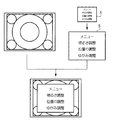
図4は、ステップS1及びS2において取得されるパラメーターを例示する図である。図4(A)は主画像のサイズを示すパラメーターを、図4(B)は補正後画像のサイズを示すパラメーターを示している。図4(B)における破線6は、表示領域のサイズを表す。主画像のサイズを示すパラメーターとしては、主画像の4頂点である点o(x0、y0)、点p(x1、y1)、点q(x2、y2)、及び点r(x3、y3)の座標が用いられる。これらの点の座標は表示領域のサイズ(液晶パネル113の解像度)に応じてあらかじめ決められている。これらの座標を示すデータは、ROM102に記憶されている。ステップS1において、CPU101は、ROM102からこの座標を示すデータを読み出すことにより、主画像のサイズを示すパラメーターを取得する。
FIG. 4 is a diagram illustrating parameters obtained in steps S1 and S2. FIG. 4A shows a parameter indicating the size of the main image, and FIG. 4B shows a parameter indicating the size of the corrected image. A
補正後画像の形状を示すパラメーターとしては、補正後画像の4頂点である点O(X0、Y0)、点P(X1、Y1)、点Q(X2、Y2)、及び点R(X3、Y3)の座標が用いられる。この場合、プロジェクター1は、まず、台形歪み補正を行わない画像(図1:画像3)を投写する。撮影部115は、スクリーン2に投写されている歪んだ画像3を撮影する。CPU101は、撮影部115により撮影された画像に基づき、歪みが補正された画像の4頂点の座標(液晶パネル113における座標)を算出する。図4(B)は、この歪みが補正された画像が液晶パネル113に表示された状態を示している。CPU101は、算出した座標を示すデータをRAM103に書き込む。
Parameters indicating the shape of the corrected image include point O (X0, Y0), point P (X1, Y1), point Q (X2, Y2), and point R (X3, Y3) that are the four vertices of the corrected image. ) Coordinates are used. In this case, the
再び図3を参照する。ステップS3において、CPU101は、座標変換係数を算出する。この座標変換係数は、液晶パネル113に表示される画像(例えば図4(B))から、フレームバッファー1032aにデータとして記憶されている画像(例えば図4(A))への変換(以下「座標変換」(座標変換処理の一例)という)を特定するパラメーターである。補正後画像を座標変換することにより、補正後画像のある画素に対応する主画像の画素の座標が得られる。この座標変換は、A〜Hの8つの座標変換係数により特定される。CPU101は、次式(1)の8元連立一次方程式を解くことにより、座標変換係数A〜Hを算出する。CPU101は、算出した座標変換係数A〜Hを示すデータをRAM103に書き込む。

ステップS4において、CPU101は、逆座標変換係数を算出する。この逆座標変換係数は、データとして記憶されている画像(図4(A))からスクリーン2に映し出される画像(図4(B))への変換(以下「逆座標変換」という)を特定するパラメーターである。この逆座標変換は、a〜hの8つの座標変換係数により特定される。CPU101は、既に取得された座標変換係数A〜H及び次式(2)を用いて、逆座標変換係数a〜hを算出する。
ステップS5において、CPU101は、複数の基準点の中から1つの基準点を選択する。例えば、複数の基準点には、識別番号が割り当てられている。CPU101は、識別番号の小さいものから順に、基準点を選択する。ステップS6において、CPU101は、選択された基準点及びこれと隣り合う画素(以下、「隣接画素」という。)について、逆座標変換を行う。具体的には、CPU101は、逆座標変換係数a〜h及び次式(3)を用いて、補正前のOSD画像における座標(xi,yi)に対して逆座標変換を行い、補正後の座標(Xi,Yi)を算出する。
図5は、基準点を例示する図である。図5(A)は、補正前画像のOSD画像5における基準点u1〜u5を示している。基準点u5は、OSD画像5の中心(重心)にある。基準点u1〜u4は、それぞれ、OSD画像5の中心からみて、左上、右上、右下、左下の所定の位置にある。図5(B)は、補正後画像のOSD画像5における基準点U1〜U5を示している。
FIG. 5 is a diagram illustrating a reference point. FIG. 5A shows reference points u1 to u5 in the
再び図3を参照する。ステップS7において、CPU101は、基準点における変形率を算出する。この例では、複数の隣接画素との関係において算出された複数の変形率の代表値が、その基準点の変形率として算出される。この例では、複数の変形率の代表値として最小値が用いられる。基準点の画素と一の隣接画素との変形率は、これら2画素の逆座標変換後の距離Dと逆座標変換前の距離dとの比である。ここでは、ユークリッド距離が2点間の距離として用いられる。
Refer to FIG. 3 again. In step S7, the
図6は、逆座標変換の前後における基準点及び隣接画素を示す図である。図6において、白丸は基準点の画素を、黒丸は隣接画素を、それぞれ示している。この例では、基準点の画素の上下左右、並びに左上、右上、右下、及び左上の計8つの画素が隣接画素として考慮される。図6(A)は、逆座標変換前の基準点及び隣接画素の位置関係を示している。破線は、画素の行及び列を示している。行の破線と列の破線の交点に画素が位置する。図6(B)は、逆座標変換後の基準点及び隣接画素の位置関係を示している。破線は、逆座標変換前の画素の行及び列を示している。図6の例では、逆座標変換により、隣接画素U12と基準点U1との距離、隣接画素U13と基準点U1との距離、及び隣接画素U16と基準点U1との距離が逆座標変換前より短くなっており、隣接画素U11と基準点U1との距離、隣接画素U14と基準点U1との距離、隣接画素U15と基準点U1との距離、隣接画素U17と基準点U1との距離、及び隣接画素U18と基準点U1との距離が逆座標変換前より長くなっている。以下、基準点uiと隣接画素uijとの距離を、距離djと表し、基準点Uiと隣接画素Uijとの距離を、距離Djと表す。CPU101は、基準点uiについて、変形率αiを算出する。この例では、次式(4)のとおり、複数の変形率の最小値が、基準点uiにおける変形率αiとして算出される。
![]()
![]()
再び図3を参照する。ステップS8において、CPU101は、全ての基準点に関して変形率が算出されたか判断する。全ての基準点に関して変形率が算出されていないと判断された場合(ステップS8:NO)、CPU101は、処理をステップS5に移行する。全ての基準点に関して変形率が算出されていると判断された場合(ステップS8:YES)、CPU101は、処理をステップS9に移行する。このように、CPU101は、全ての基準点に関して変形率が算出されるまで、ステップS5からステップS7の処理を繰り返す。OSD画像5の例では、基準点u1〜u5の全てについて、それぞれ変形率が決定される。
Refer to FIG. 3 again. In step S8, the
ステップS9において、CPU101は、OSD画像5におけるOSD変形率を決定する。この例では、ステップS5からステップS7において算出された複数の変形率の代表値が、OSD変形率として決定される。代表値としては、最小値が用いられる。OSD変形率が1に近いほど、台形歪み補正によってOSD画像が変形される度合いが小さい。OSD変形率が0に近いほど、OSD画像の中に、台形歪み補正によって縮小される度合いの大きい部分が存在する。
In step S <b> 9, the
ステップS10において、CPU101は、OSD変形率に基づいてOSD拡大率を決定する。OSD拡大率とは、OSD画像のサイズを拡大するための倍率を示す値である。この例で、ROM102は、OSD変形率に対してOSD拡大率を決定する関数を記憶している。CPU101は、この関数を用いて、OSD変形率に対応するOSD拡大率を決定する。CPU101は、決定されたOSD拡大率をRAM103に書き込む。
In step S10, the
図7は、OSD変形率とOSD拡大率との関係、すなわちOSD拡大率を決定する関数を例示する図である。この関数において、OSD変形率が1以上の領域では、OSD拡大率はOSD変形率によらず1で一定である。OSD変形率が0以上1未満の領域においては、OSD拡大率は、最大値Emから1まで減少する減少関数となっている。 FIG. 7 is a diagram illustrating a relationship between the OSD deformation ratio and the OSD enlargement ratio, that is, a function for determining the OSD enlargement ratio. In this function, in the region where the OSD deformation rate is 1 or more, the OSD enlargement rate is constant at 1 regardless of the OSD deformation rate. In the region where the OSD deformation rate is 0 or more and less than 1, the OSD enlargement rate is a decreasing function that decreases from the maximum value Em to 1.
図8は、OSD拡大率の最大値Emを決定する方法を説明する図である。最大値は、拡大後のOSD画像が、主画像のサイズを超えない範囲において、OSD拡大率が最大となるように決定される。OSD画像5の横幅をWo、高さをHoとし、主画像の横幅をWi、高さをHiとすると、最大値Emは、例えば次式(5)により決定される。
図9は、合成画像の生成方法の概要を示す図である。CPU101からOSD描画命令を受けると、OSDスケーラー108は、RAM103に記憶されているOSDデータ及びOSD拡大率を読み出す。OSDスケーラー108は、読み出したOSD拡大率でOSD画像5を拡大する。画像合成部109は、主画像と拡大されたOSD画像5とを合成し、合成画像データを生成する。主画像とOSD画像とを合成する際の主画像とOSD画像との位置関係を示す情報は、ROM102に記憶されている。例えば、OSD画像と主画像とは、重心が一致するように合成される。別の例で、OSD画像と主画像とは、OSD画像の基準点(例えば左上頂点)が、主画像の決められた点に位置するように合成されてもよい。
FIG. 9 is a diagram showing an outline of a method for generating a composite image. When receiving the OSD drawing command from the
台形歪み補正部110は、画像合成部109により生成された合成画像データに対して台形歪み補正を行う。具体的には、台形歪み補正部110は、座標変換係数A〜H及び次式(6)を用いて、補正後画像における座標(Xj, Yj)に対して座標変換を行い、合成画像における座標(xj, yj)を算出する。
図10は、OSD変形率に応じたOSD拡大率の決定を行った場合と行わなかった場合とを対比する図である。図10(A)は、本実施形態で説明したように、OSD変形率に応じて決定されたOSD拡大率を用いて合成及び台形歪み補正が行われた画像を例示する図である。図10(B)は、OSD変形率によらず一定(例えば1倍)のOSD拡大率を用いて合成及び台形歪み補正が行われた画像を例示する図である。図10(A)のOSD画像5は、(B)のOSD画像5に比較してサイズが大きくなるので、OSD画像の視認性が向上する。
FIG. 10 is a diagram comparing the case where the OSD enlargement rate is determined according to the OSD deformation rate and the case where the OSD enlargement rate is not determined. FIG. 10A is a diagram illustrating an image that has been combined and trapezoidally corrected using the OSD enlargement rate determined according to the OSD deformation rate, as described in the present embodiment. FIG. 10B is a diagram illustrating an image that has been synthesized and trapezoidally corrected using a constant (for example, 1 time) OSD enlargement ratio regardless of the OSD deformation ratio. Since the
<変形例>
本発明は、上述の実施形態に限定されるものではなく、種々の変形実施が可能である。以下、変形例をいくつか説明する。以下で説明する変形例のうち、2つ以上のものが組み合わされて用いられても良い。
<Modification>
The present invention is not limited to the above-described embodiments, and various modifications can be made. Hereinafter, some modifications will be described. Of the modifications described below, two or more may be used in combination.
(1)変形例1
基準点の位置は、OSD画像の中心及び四隅に限定されず、OSD画像のどこであってもよい。また、基準点の分布は、均等でなくてもよい。例えば、台形歪み補正により変形が大きく生じることが予想される位置に基準点を設けてもよいし、OSD画像において一番小さい文字が表示される位置に基準点を設けてもよい。また、これらの位置に他の領域よりも多くの基準点を設けてもよい。
(1)
The position of the reference point is not limited to the center and the four corners of the OSD image, and may be anywhere in the OSD image. Further, the distribution of the reference points may not be uniform. For example, a reference point may be provided at a position where a large deformation is expected to occur due to trapezoidal distortion correction, or a reference point may be provided at a position where the smallest character is displayed in the OSD image. In addition, more reference points may be provided at these positions than in other regions.
(2)変形例2
プロジェクター1は、複数のOSDデータを記憶していてもよい。この場合、複数のOSD画像の中から選択された一のOSD画像が用いられる。この場合において、基準点の位置又は数はOSD画像毎に設定されていてもよい。例えば、OSD画像の形状に応じた位置に基準点が設定されていてもよい。ROM102は、OSD画像と基準点との対応関係を示すデータを記憶する。
(2)
The
(3)変形例3
OSD変形率は、基準点の画素と隣接画素とのユークリッド距離を用いて算出されたものに限定されない。例えば、基準点及び複数の隣接画素について、ある画素と当該画素に水平方向に隣り合う画素との関係で算出された複数の変形率の代表値が、その基準点の変形率として算出されてもよい。この場合、ある画素と当該画素に水平方向に隣り合う画素との変形率は、これら2画素の逆座標変換後の水平方向における距離Dである(変換前の画素間の距離を1とした場合)。同様の例で、ある画素と当該画素に垂直方向に隣り合う画素との関係で算出された複数の変形率の代表値が、その基準点の変形率として算出されてもよい。この場合、ある画素と当該画素に垂直方向に隣り合う画素との変形率は、これら2画素の逆座標変換後の垂直方向における距離Dである。
(3)
The OSD deformation rate is not limited to the one calculated using the Euclidean distance between the reference point pixel and the adjacent pixel. For example, for a reference point and a plurality of adjacent pixels, a representative value of a plurality of deformation rates calculated in a relationship between a pixel and a pixel adjacent to the pixel in the horizontal direction may be calculated as the deformation rate of the reference point. Good. In this case, the deformation rate between a pixel and a pixel adjacent to the pixel in the horizontal direction is the distance D in the horizontal direction after inverse coordinate conversion of these two pixels (when the distance between the pixels before conversion is 1). ). In a similar example, representative values of a plurality of deformation rates calculated in relation to a pixel and a pixel adjacent to the pixel in the vertical direction may be calculated as the deformation rate of the reference point. In this case, the deformation ratio between a certain pixel and a pixel adjacent to the pixel in the vertical direction is a distance D in the vertical direction after inverse coordinate conversion of these two pixels.
図11は、変形例3に係る変形率算出の方法を示す図である。図11は、逆座標変換後の基準点及び隣接画素の位置関係を示している。基準点及び隣接画素の位置関係は図6(B)と等しい。図11(A)に示されるD12、D23,D08、D04、D67及びD56は、ある画素と当該画素に水平方向に隣り合う画素との関係で算出される複数の変形率を示している。図11(A)の例では、距離D12〜D56は、逆座標変換前より長くなっている。この例では、CPU101は、基準点u1について、距離D12〜D56のうち最小値であるD23を変形率α1として算出する。図11(B)に示されるD18、D78、D02、D06、D34及びD45は、ある画素と当該画素に垂直方向に隣り合う画素との関係で算出される複数の変形率を示している。この例では、CPU101は、基準点u1について、距離D18〜D45のうち最小値であるD06(並びにD34、D45及びD78)を変形率α1として算出する。
FIG. 11 is a diagram illustrating a deformation rate calculation method according to the third modification. FIG. 11 shows the positional relationship between the reference point and the adjacent pixels after the inverse coordinate transformation. The positional relationship between the reference point and adjacent pixels is the same as that in FIG. D12, D23, D08, D04, D67, and D56 shown in FIG. 11A indicate a plurality of deformation rates calculated based on a relationship between a certain pixel and a pixel that is adjacent to the pixel in the horizontal direction. In the example of FIG. 11A, the distances D12 to D56 are longer than before the inverse coordinate conversion. In this example, the
別の例で、基準点及び複数の隣接画素について、ある画素と当該画素に水平方向及び垂直方向に隣り合う画素との関係で算出された複数の変形率の代表値が、その基準点の変形率として算出されてもよい。この場合、上述の水平方向に隣り合う画素との関係で算出された複数の変形率(図11(A))と垂直方向に隣り合う画素との関係で算出された複数の変形率(図11(B))のうち最小値が変形率αiとなる。 In another example, for a reference point and a plurality of adjacent pixels, representative values of a plurality of deformation rates calculated based on the relationship between a pixel and a pixel adjacent to the pixel in the horizontal direction and the vertical direction are the deformations of the reference point. It may be calculated as a rate. In this case, a plurality of deformation ratios calculated in relation to the pixels adjacent in the horizontal direction (FIG. 11A) and a plurality of deformation ratios calculated in relation to the pixels adjacent in the vertical direction (FIG. 11). The minimum value of (B)) is the deformation rate αi.
(4)変形例4
ステップS7において、対象となる基準点における変形率の算出で用いられる代表値は、複数の変形率の最小値に限定されない。複数の変形率の平均値が、代表値として用いられてもよい。別の例で、複数の変形率のうち特定の順番(例えば、下から2番目)にある変形率が、代表値として用いられてもよい。また、複数の変形率に応じて、用いられる代表値が切り替えられてもよい。例えば、代表値として最小値を用いることが原則として決められている場合に、最小値があらかじめ決められたしきい値より小さいときは、下から2番目の変形率が代表値として用いられてもよい。
(4) Modification 4
In step S7, the representative value used in the calculation of the deformation rate at the target reference point is not limited to the minimum value of the plurality of deformation rates. An average value of a plurality of deformation rates may be used as a representative value. In another example, a deformation rate in a specific order (for example, second from the bottom) among a plurality of deformation rates may be used as a representative value. Moreover, the representative value used may be switched according to a plurality of deformation rates. For example, when it is determined in principle to use the minimum value as the representative value, and the minimum value is smaller than a predetermined threshold value, the second deformation rate from the bottom may be used as the representative value. Good.
(5)変形例5
ステップS9において、OSD変形率として決定される変形率の代表値は、最小値に限定されない。基準点における変形率の平均値、又は基準点における変形率のうち特定の順番(例えば、下から2番目)にある変形率が、代表値とされてもよい。また、基準点の変形率を算出する場合の変形例(変形例4)と同様に、複数の変形率に応じて、用いられる代表値が切り替えられてもよい。
(5)
In step S9, the representative value of the deformation rate determined as the OSD deformation rate is not limited to the minimum value. The average value of the deformation rate at the reference point or the deformation rate in a specific order (for example, second from the bottom) among the deformation rates at the reference point may be used as the representative value. Further, similarly to the modification example (modification example 4) in the case of calculating the deformation rate of the reference point, the representative value to be used may be switched according to a plurality of deformation rates.
(6)変形例6
変形率の算出で用いられる画素は、基準点の隣接画素に限定されない。例えば、基準点から特定の距離(例えば、5画素分の距離)にある画素との関係で、複数の変形率が算出されてもよい。
(6)
The pixels used for calculating the deformation rate are not limited to the pixels adjacent to the reference point. For example, a plurality of deformation rates may be calculated in relation to a pixel at a specific distance from the reference point (for example, a distance of 5 pixels).
(7)変形例7
ステップS2における補正画像のパラメーターを算出する処理は、撮影部115により撮影された画像を用いるものに限定されない。CPU101は、投写軸の理想状態からの傾きを用いて、補正画像のパラメーターを算出してもよい。この場合、プロジェクター1は、傾きセンサー(加速度センサー)を有している。CPU101は、傾きセンサーにより検出された投写軸の理想状態からの傾きから、補正後画像の4頂点の座標(図4(B))を算出する。
(7) Modification 7
The process for calculating the parameters of the corrected image in step S2 is not limited to using the image captured by the
(8)その他の変形例
プロジェクター1のハードウェア構成は、図2で説明したものに限定されない。図3で説明したフローおよび各ステップの処理を実行できるのであれば、プロジェクター1はどのようなハードウェア構成を有していてもよい。
第1画像はOSD画像に限定されず、第2画像と合成されて投写される画像であればよい。例えば、第2画像に対して補助的な役割を果たすための画像などであってもよい。
プロジェクター1は台形歪み補正を行うが、「補正処理」はこの台形歪み補正に限定されない。「補正処理」は、合成画像データの変形を行う処理であればよい。
OSD拡大率を決定する関数は図7で説明したものに限定されない。OSD変形率が0以上1未満の領域において、OSD拡大率がOSD変形率に対して非線形であってもよい。
(8) Other Modifications The hardware configuration of the
The first image is not limited to the OSD image, and may be an image that is combined with the second image and projected. For example, an image for playing an auxiliary role with respect to the second image may be used.
The
The function for determining the OSD enlargement ratio is not limited to that described with reference to FIG. In a region where the OSD deformation rate is 0 or more and less than 1, the OSD enlargement rate may be nonlinear with respect to the OSD deformation rate.
1…プロジェクター、2…スクリーン、3,4…画像、5…OSD画像(第1画像)、101…CPU、102…ROM(記憶手段)、103…RAM、104…映像取得部、105…画像処理部、106…画像スケーラー、107…OSD描画部、108…OSDスケーラー、109…画像合成部(合成画像生成手段)、110…台形歪み補正部(補正手段)、111…パネル駆動部、112…照明光学系(投写手段)、113…液晶パネル(投写手段)、114…投写光学系(投写手段)、115…撮影部、1011…座標変換係数算出部(変換係数取得手段)、1012…第1変形率算出部(変形率算出手段)、1013…第2変形率決定部(変形率決定手段)、1031…OSDバッファー、1032a,1032b…フレームバッファー
DESCRIPTION OF
Claims (7)
前記変形率算出手段によって算出された第1変形率に基づいて、前記第1画像のサイズを変更するための第2変形率を決定する変形率決定手段と、
第2画像データにより示される第2画像と、前記変形率決定手段により決定された第2変形率に基づいてサイズが変更された前記第1画像とを合成した合成画像を示す合成画像データを生成する合成画像生成手段と、
前記合成画像生成手段により生成された合成画像データに、前記補正処理を行う補正手段と、
前記補正処理が行われた前記合成画像データに基づいて前記合成画像を投写する投写手段と、
前記第1画像と前記第2画像との位置関係を示す位置情報を記憶する位置情報記憶手段と、を有し、
前記合成画像生成手段は、前記位置情報記憶手段に記憶された前記位置情報に基づき、前記第1画像と前記第2画像の重心が一致するように、前記第2画像に対して前記第1画像を合成する
ことを特徴とするプロジェクター。 A deformation rate calculating means for calculating a first deformation rate at a reference point set in the first image when correction processing is performed on the first image data indicating the first image;
Deformation rate determining means for determining a second deformation rate for changing the size of the first image based on the first deformation rate calculated by the deformation rate calculating means;
Generates composite image data indicating a composite image obtained by combining the second image indicated by the second image data and the first image whose size has been changed based on the second deformation rate determined by the deformation rate determining means. A composite image generating means for
Correction means for performing the correction process on the composite image data generated by the composite image generation means;
Projection means for projecting the composite image based on the composite image data subjected to the correction processing;
Position information storage means for storing position information indicating a positional relationship between the first image and the second image;
The composite image generating means, based-out to the position information stored before Symbol positional information storage section, as the center of gravity of the first image and the second image are matched, the relative said second image A projector characterized in that the first image is synthesized.
前記座標変換係数を取得する変換係数取得手段を備え、
前記変形率算出手段は、前記変換係数取得手段により取得された前記座標変換係数に基づいて、前記第1変形率を算出する
ことを特徴とする請求項1に記載のプロジェクター。 The correction process includes a coordinate conversion process using a coordinate conversion coefficient,
Comprising conversion coefficient acquisition means for acquiring the coordinate conversion coefficient;
The projector according to claim 1, wherein the deformation rate calculation unit calculates the first deformation rate based on the coordinate conversion coefficient acquired by the conversion coefficient acquisition unit.
前記変形率算出手段は、前記複数の基準点について前記第1変形率を算出し、
前記変形率決定手段は、前記複数の基準点について算出された前記第1変形率の代表値に基づいて、前記第2変形率を決定する
ことを特徴とする請求項1又は2に記載のプロジェクター。 A plurality of reference points are set in the first image,
The deformation rate calculating means calculates the first deformation rate for the plurality of reference points,
3. The projector according to claim 1, wherein the deformation rate determining unit determines the second deformation rate based on a representative value of the first deformation rate calculated for the plurality of reference points. .
前記基準点は、前記複数の第1画像データにより示される複数の第1画像毎に設定されている
ことを特徴とする請求項1乃至3のいずれか一項に記載のプロジェクター。 Image data storage means for storing a plurality of the first image data;
The projector according to any one of claims 1 to 3 , wherein the reference point is set for each of a plurality of first images indicated by the plurality of first image data.
ことを特徴とする請求項1乃至4のいずれか一項に記載のプロジェクター。 The first image projector according to any one of claims 1 to 4, characterized in that it is OSD (On Screen Display) image.
前記変形率算出部によって算出された変形率に基づいて、前記OSD画像のサイズを変更するための拡大率を決定する拡大率決定部と、
主画像と、前記拡大率決定部によって決定された拡大率に基づいてサイズが変更されたOSD画像と、を合成した合成画像を示す合成画像データを生成する合成画像生成部と、
前記合成画像生成部により生成された合成画像データに前記台形歪み補正を行う台形歪み補正部と、
前記台形歪み補正が行われた合成画像データに基づいて前記合成画像を投写する投写光学系と、
前記主画像と前記OSD画像との位置関係を示す位置情報を記憶する位置情報記憶部と、を有し、
前記合成画像生成部は、前記位置情報記憶部に記憶された前記位置情報に基づき、前記OSD画像と前記主画像の重心が一致するように、前記主画像に対して前記OSD画像を合成する
ことを特徴とするプロジェクター。 A deformation rate calculation unit for calculating a deformation rate at a reference point set in the OSD image when trapezoidal distortion correction is performed on the OSD data indicating the OSD image;
An enlargement rate determining unit that determines an enlargement rate for changing the size of the OSD image based on the deformation rate calculated by the deformation rate calculating unit;
A composite image generation unit that generates composite image data indicating a composite image obtained by combining a main image and an OSD image whose size has been changed based on the enlargement factor determined by the enlargement factor determination unit;
A trapezoidal distortion correction unit that performs the trapezoidal distortion correction on the composite image data generated by the composite image generation unit;
A projection optical system for projecting the composite image based on the composite image data subjected to the trapezoidal distortion correction;
A positional information storage unit that stores positional information indicating a positional relationship between the main image and the OSD image;
The composite image generation unit, based-out to the position information stored before Symbol position information storage unit, the so that the center of gravity of the OSD image and the main image are matched, the OSD image to the main image A projector characterized by combining.
前記第1変形率に基づいて、前記第1画像のサイズを変更するための第2変形率を決定する工程と、
第2画像データにより示される第2画像と、前記第2変形率に基づいてサイズが変更された前記第1画像とを合成した合成画像を示す合成画像データを生成する工程と、
前記合成画像データに、前記補正処理を行う工程と、を有し、
前記合成画像データを生成する工程では、記憶手段に記憶されている前記第1画像と前記第2画像との位置関係を示す位置情報に基づき、前記第1画像と前記第2画像の重心が一致するように、前記第2画像に対して前記第1画像を合成する
ことを特徴とするプロジェクターの制御方法。 Calculating a first deformation rate at a reference point set in the first image when correction processing is performed on the first image data indicating the first image;
Determining a second deformation rate for changing the size of the first image based on the first deformation rate;
Generating composite image data indicating a composite image obtained by combining the second image indicated by the second image data and the first image whose size has been changed based on the second deformation rate;
Performing the correction process on the composite image data,
Wherein in the step of generating a composite image data, serial-out based on the position information indicating the positional relationship between the first image stored in憶means and the second image, the first image and the second image The projector control method , wherein the first image is synthesized with the second image so that the centers of gravity coincide with each other .
Priority Applications (2)
| Application Number | Priority Date | Filing Date | Title |
|---|---|---|---|
| JP2011159628A JP5997882B2 (en) | 2011-07-21 | 2011-07-21 | Projector and projector control method |
| US13/547,163 US9224321B2 (en) | 2011-07-21 | 2012-07-12 | Projector for performing trapezoidal distortion correction and method of controlling projector |
Applications Claiming Priority (1)
| Application Number | Priority Date | Filing Date | Title |
|---|---|---|---|
| JP2011159628A JP5997882B2 (en) | 2011-07-21 | 2011-07-21 | Projector and projector control method |
Publications (3)
| Publication Number | Publication Date |
|---|---|
| JP2013025077A JP2013025077A (en) | 2013-02-04 |
| JP2013025077A5 JP2013025077A5 (en) | 2014-08-28 |
| JP5997882B2 true JP5997882B2 (en) | 2016-09-28 |
Family
ID=47555557
Family Applications (1)
| Application Number | Title | Priority Date | Filing Date |
|---|---|---|---|
| JP2011159628A Expired - Fee Related JP5997882B2 (en) | 2011-07-21 | 2011-07-21 | Projector and projector control method |
Country Status (2)
| Country | Link |
|---|---|
| US (1) | US9224321B2 (en) |
| JP (1) | JP5997882B2 (en) |
Families Citing this family (12)
| Publication number | Priority date | Publication date | Assignee | Title |
|---|---|---|---|---|
| JP5870586B2 (en) * | 2011-09-28 | 2016-03-01 | カシオ計算機株式会社 | Projector control device, display device, and program. |
| JP5924020B2 (en) * | 2012-02-16 | 2016-05-25 | セイコーエプソン株式会社 | Projector and projector control method |
| JP5910440B2 (en) * | 2012-09-28 | 2016-04-27 | ソニー株式会社 | Image output apparatus, image output method, and program |
| JP6217110B2 (en) * | 2013-03-29 | 2017-10-25 | セイコーエプソン株式会社 | Projector and adjustment method |
| JP6306834B2 (en) | 2013-07-24 | 2018-04-04 | キヤノン株式会社 | Image processing apparatus and image processing method |
| JP6228469B2 (en) * | 2014-01-20 | 2017-11-08 | 株式会社東芝 | Image processing apparatus, image processing method, and image projection apparatus |
| JP6418010B2 (en) * | 2015-03-02 | 2018-11-07 | セイコーエプソン株式会社 | Image processing apparatus, image processing method, and display apparatus |
| JP2017191572A (en) * | 2016-04-15 | 2017-10-19 | キヤノン株式会社 | Image processor, method thereof, and program |
| JP6789720B2 (en) * | 2016-08-10 | 2020-11-25 | キヤノン株式会社 | Image processing equipment, image processing methods and programs |
| JP2018125719A (en) * | 2017-02-01 | 2018-08-09 | キヤノン株式会社 | System, information processing device, information processing method, and program |
| JP6897191B2 (en) * | 2017-03-17 | 2021-06-30 | セイコーエプソン株式会社 | Projector and projector control method |
| CN113646203A (en) * | 2019-03-29 | 2021-11-12 | 罗姆股份有限公司 | Semiconductor device, and in-vehicle display system and electronic apparatus using the same |
Family Cites Families (29)
| Publication number | Priority date | Publication date | Assignee | Title |
|---|---|---|---|---|
| JPH1173290A (en) * | 1997-07-03 | 1999-03-16 | Funai Electric Co Ltd | Menu display device |
| JP4252671B2 (en) * | 1999-05-21 | 2009-04-08 | セイコーエプソン株式会社 | Projection display |
| DE69930152T2 (en) * | 1999-12-24 | 2006-08-10 | Matsushita Electric Industrial Co., Ltd., Kadoma | PROJECTOR |
| JP2002158946A (en) * | 2000-11-20 | 2002-05-31 | Seiko Epson Corp | Projector and method for correcting image distortion |
| JP3646658B2 (en) * | 2001-03-01 | 2005-05-11 | セイコーエプソン株式会社 | Image distortion correction |
| JP2003153135A (en) * | 2001-11-16 | 2003-05-23 | Sanyo Electric Co Ltd | Projection display device |
| DE60306207T2 (en) * | 2003-01-09 | 2007-05-03 | Koninklijke Philips Electronics N.V. | Video Projector with Image Stabilizers |
| JP3630166B2 (en) * | 2003-06-26 | 2005-03-16 | セイコーエプソン株式会社 | Adjusting the amount of distortion correction in the projected image |
| CN100460993C (en) * | 2003-07-17 | 2009-02-11 | 三洋电机株式会社 | Projection type video display |
| JP3960972B2 (en) * | 2004-01-16 | 2007-08-15 | 三洋電機株式会社 | Projection display device |
| JP2006014233A (en) | 2004-06-29 | 2006-01-12 | Toshiba Corp | Trapezoidal distortion correcting apparatus for projection type projector |
| JP2006246306A (en) * | 2005-03-07 | 2006-09-14 | Seiko Epson Corp | Projector and its control method |
| JP2008244981A (en) * | 2007-03-28 | 2008-10-09 | Seiko Epson Corp | Video synthesis device and video output device |
| JP2009177581A (en) * | 2008-01-25 | 2009-08-06 | Necディスプレイソリューションズ株式会社 | Projection type display device and caption display method |
| JP2009200557A (en) * | 2008-02-19 | 2009-09-03 | Seiko Epson Corp | Projector, electronic apparatus, and method of controlling projector |
| JP2009216815A (en) * | 2008-03-07 | 2009-09-24 | Sanyo Electric Co Ltd | Projection type video display device |
| JP5217537B2 (en) | 2008-03-18 | 2013-06-19 | セイコーエプソン株式会社 | Projector, electronic device, and projector control method |
| JP5405047B2 (en) * | 2008-05-09 | 2014-02-05 | 三洋電機株式会社 | Projection display device |
| JP5098869B2 (en) * | 2008-07-22 | 2012-12-12 | セイコーエプソン株式会社 | Image processing apparatus, image display apparatus, and image data generation method |
| US8159760B2 (en) * | 2008-08-19 | 2012-04-17 | Seiko Epson Corporation | Projector and control method of projector |
| JP5310266B2 (en) * | 2009-05-29 | 2013-10-09 | セイコーエプソン株式会社 | Projector and control method thereof |
| JP2010054550A (en) * | 2008-08-26 | 2010-03-11 | Seiko Epson Corp | Image display device, projector, program, and information storage medium |
| JP2010152267A (en) * | 2008-12-26 | 2010-07-08 | Seiko Epson Corp | Projector |
| JP2011033857A (en) * | 2009-08-03 | 2011-02-17 | Seiko Epson Corp | Projector and method of controlling the same |
| JP2011065025A (en) * | 2009-09-18 | 2011-03-31 | Sanyo Electric Co Ltd | Projection type image display device |
| JP2011066738A (en) * | 2009-09-18 | 2011-03-31 | Sanyo Electric Co Ltd | Projection type video display device |
| JP5442393B2 (en) * | 2009-10-29 | 2014-03-12 | 日立コンシューマエレクトロニクス株式会社 | Display device |
| JP5441672B2 (en) * | 2009-12-25 | 2014-03-12 | キヤノン株式会社 | Projection display |
| JP5832119B2 (en) * | 2011-04-06 | 2015-12-16 | キヤノン株式会社 | Projection apparatus, control method thereof, and program |
-
2011
- 2011-07-21 JP JP2011159628A patent/JP5997882B2/en not_active Expired - Fee Related
-
2012
- 2012-07-12 US US13/547,163 patent/US9224321B2/en not_active Expired - Fee Related
Also Published As
| Publication number | Publication date |
|---|---|
| JP2013025077A (en) | 2013-02-04 |
| US9224321B2 (en) | 2015-12-29 |
| US20130021585A1 (en) | 2013-01-24 |
Similar Documents
| Publication | Publication Date | Title |
|---|---|---|
| JP5997882B2 (en) | Projector and projector control method | |
| US9818377B2 (en) | Projection system, image processing apparatus, and correction method | |
| JP4055010B2 (en) | Image processing system, projector, program, information storage medium, and image processing method | |
| JP5842694B2 (en) | Image processing apparatus, projector, and projector control method | |
| JP6089424B2 (en) | Image processing apparatus, projector, and projector control method | |
| JP4340923B2 (en) | Projector, program, and information storage medium | |
| JP3880609B1 (en) | Image projection method and projector | |
| JP5348022B2 (en) | Projector and projection conversion processing apparatus | |
| JP4871820B2 (en) | Video display system and parameter generation method for the system | |
| WO2013024540A1 (en) | Image processing apparatus and image processing method | |
| JP2011193332A (en) | Projector and video projection method | |
| JP5348035B2 (en) | projector | |
| JP5515405B2 (en) | Video processing device, video display device, and video processing method | |
| JP6418010B2 (en) | Image processing apparatus, image processing method, and display apparatus | |
| JP2015192177A (en) | Image processor, display device, and image processing method | |
| JP6221287B2 (en) | Projector and projector control method | |
| JP2010288062A (en) | Projector, program, information storage medium, and image projection method | |
| JP5915001B2 (en) | Projector and projector control method | |
| JP3882927B2 (en) | Image processing system, projector, and image processing method | |
| JP2012230302A (en) | Image generation device, projection type image display device, image display system, image generation method and computer program | |
| JP5093517B2 (en) | Projector, program, information storage medium, and image generation method | |
| JP5353772B2 (en) | projector | |
| JP2020191586A (en) | Projection device | |
| JP5531701B2 (en) | projector | |
| US20230209026A1 (en) | Projection method and projector |
Legal Events
| Date | Code | Title | Description |
|---|---|---|---|
| A521 | Request for written amendment filed |
Free format text: JAPANESE INTERMEDIATE CODE: A523 Effective date: 20140714 |
|
| A621 | Written request for application examination |
Free format text: JAPANESE INTERMEDIATE CODE: A621 Effective date: 20140714 |
|
| RD04 | Notification of resignation of power of attorney |
Free format text: JAPANESE INTERMEDIATE CODE: A7424 Effective date: 20150107 |
|
| A977 | Report on retrieval |
Free format text: JAPANESE INTERMEDIATE CODE: A971007 Effective date: 20150408 |
|
| A131 | Notification of reasons for refusal |
Free format text: JAPANESE INTERMEDIATE CODE: A131 Effective date: 20150512 |
|
| A521 | Request for written amendment filed |
Free format text: JAPANESE INTERMEDIATE CODE: A523 Effective date: 20150708 |
|
| A02 | Decision of refusal |
Free format text: JAPANESE INTERMEDIATE CODE: A02 Effective date: 20150929 |
|
| A521 | Request for written amendment filed |
Free format text: JAPANESE INTERMEDIATE CODE: A523 Effective date: 20151222 |
|
| A911 | Transfer to examiner for re-examination before appeal (zenchi) |
Free format text: JAPANESE INTERMEDIATE CODE: A911 Effective date: 20160105 |
|
| A912 | Re-examination (zenchi) completed and case transferred to appeal board |
Free format text: JAPANESE INTERMEDIATE CODE: A912 Effective date: 20160212 |
|
| A61 | First payment of annual fees (during grant procedure) |
Free format text: JAPANESE INTERMEDIATE CODE: A61 Effective date: 20160829 |
|
| R150 | Certificate of patent or registration of utility model |
Ref document number: 5997882 Country of ref document: JP Free format text: JAPANESE INTERMEDIATE CODE: R150 |
|
| LAPS | Cancellation because of no payment of annual fees |