JP3827662B2 - Projection display - Google Patents
Projection display Download PDFInfo
- Publication number
- JP3827662B2 JP3827662B2 JP2003318285A JP2003318285A JP3827662B2 JP 3827662 B2 JP3827662 B2 JP 3827662B2 JP 2003318285 A JP2003318285 A JP 2003318285A JP 2003318285 A JP2003318285 A JP 2003318285A JP 3827662 B2 JP3827662 B2 JP 3827662B2
- Authority
- JP
- Japan
- Prior art keywords
- projection
- vertex
- display device
- image
- screen
- Prior art date
- Legal status (The legal status is an assumption and is not a legal conclusion. Google has not performed a legal analysis and makes no representation as to the accuracy of the status listed.)
- Expired - Fee Related
Links
- 230000003287 optical effect Effects 0.000 claims description 43
- 238000001514 detection method Methods 0.000 claims description 20
- 230000001133 acceleration Effects 0.000 claims description 10
- 238000003702 image correction Methods 0.000 claims description 6
- 230000015572 biosynthetic process Effects 0.000 claims description 3
- 239000011159 matrix material Substances 0.000 claims description 3
- 238000003786 synthesis reaction Methods 0.000 claims description 3
- 238000010586 diagram Methods 0.000 description 9
- 230000006835 compression Effects 0.000 description 2
- 238000007906 compression Methods 0.000 description 2
- 230000000694 effects Effects 0.000 description 2
- 238000009434 installation Methods 0.000 description 2
- 239000004973 liquid crystal related substance Substances 0.000 description 2
- 238000000034 method Methods 0.000 description 2
- 206010052804 Drug tolerance Diseases 0.000 description 1
- 230000003247 decreasing effect Effects 0.000 description 1
- 230000026781 habituation Effects 0.000 description 1
- 238000004519 manufacturing process Methods 0.000 description 1
Images


Classifications
-
- H—ELECTRICITY
- H04—ELECTRIC COMMUNICATION TECHNIQUE
- H04N—PICTORIAL COMMUNICATION, e.g. TELEVISION
- H04N9/00—Details of colour television systems
- H04N9/12—Picture reproducers
- H04N9/31—Projection devices for colour picture display, e.g. using electronic spatial light modulators [ESLM]
- H04N9/3179—Video signal processing therefor
- H04N9/3185—Geometric adjustment, e.g. keystone or convergence
-
- H—ELECTRICITY
- H04—ELECTRIC COMMUNICATION TECHNIQUE
- H04N—PICTORIAL COMMUNICATION, e.g. TELEVISION
- H04N5/00—Details of television systems
- H04N5/74—Projection arrangements for image reproduction, e.g. using eidophor
Landscapes
- Engineering & Computer Science (AREA)
- Multimedia (AREA)
- Signal Processing (AREA)
- Physics & Mathematics (AREA)
- Geometry (AREA)
- Transforming Electric Information Into Light Information (AREA)
- Projection Apparatus (AREA)
- Video Image Reproduction Devices For Color Tv Systems (AREA)
Description
本発明は、液晶プロジェクタなどの投射型表示装置に関し、特に、光学像を投射レンズを介してスクリーン上に拡大投射するもので、スクリーンに対して光学像を垂直および水平の斜め方向に投射したときに生じる映像歪の補正をユーザが容易に行うことのできる投射型表示装置に関する。 The present invention relates to a projection display device such as a liquid crystal projector, and particularly to an optical image that is enlarged and projected onto a screen via a projection lens, and when the optical image is projected vertically and horizontally obliquely with respect to the screen. The present invention relates to a projection type display device that allows a user to easily correct image distortion that occurs in the system.
従来、この種の投射型表示装置(プロジェクタ)は、スクリーンの中心よりも下側にプロジェクタを配置し、投射レンズを上向きにして拡大投射することが一般的であるが、このとき、スクリーンに投射された投射像は逆台形形状(上辺が下辺より長い台形)の歪を生じ、また、スクリーンに対し水平方向(左右方向)に傾斜して配置したときは、投射画像の左上側、或いは、右上側がさらに広がり、より複雑な台形形状を呈する歪を生じる。 Conventionally, this type of projection-type display device (projector) generally has a projector disposed below the center of the screen and projects an enlarged projection with the projection lens facing upward. The projected image has a reverse trapezoidal shape (a trapezoid whose upper side is longer than the lower side), and when it is tilted horizontally (left and right) with respect to the screen, the upper left or upper right of the projected image The side further expands, resulting in a distortion with a more complex trapezoidal shape.
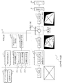
ここで、プロジェクタの配置状態とスクリーンに投射された投射像との関係を図8に示す。 Here, the relationship between the arrangement state of the projector and the projected image projected on the screen is shown in FIG.
図8を参照すると、スクリーン101に対して、プロジェクタ100の投射レンズ102からの投射に傾斜のない投射光軸aのときは、傾斜歪のない長方形の本来の投射像dとなるが、光軸が垂直傾斜bのときは、スクリーン101に投射された投射像が逆台形形状の垂直傾斜投射像eとなり、光軸が右方向に傾斜した水平傾斜cのときは、投射画像の右上側がさらに広がり、より複雑な歪を持つ台形形状の水平垂直傾斜投射像fとなる。
Referring to FIG. 8, when the projection from the
そこで、プロジェクタ100の図8の配置状態(投射レンズを上向き、右方向に傾斜したとき)での台形歪補正について、図面を参照して説明する。
Accordingly, trapezoidal distortion correction in the arrangement state of the
図9(a)〜図9(c)は、台形歪補正を説明するための図である。 FIG. 9A to FIG. 9C are diagrams for explaining trapezoidal distortion correction.
図9(a)から図9(b)は、垂直補正を行うときの、画像表示デバイス(液晶パネル)上の映像表示範囲115内に表示する表示映像113を示し、スクリーン101上の投射画像の逆台形形状の歪と逆方向に画像表示デバイス(図示せず)上の表示映像を歪ませることにより、投射画像の画像歪を補正し、長方形となるように補正を行うが、この垂直方向の補正は、図示省略するが、画像表示デバイス上の表示画像上で、投射画像の上辺に対応するラインの圧縮率を高くし、下辺に向かうに従って圧縮率を低下させていくことにより、行われる。
FIGS. 9A to 9B show a
図9(b)から図9(c)は、垂直補正後、水平補正を行うときの、画像表示デバイス上に表示する表示映像113を示している。
FIG. 9B to FIG. 9C show a
この例では、図9(a)から図9(b)において、左上頂点P101と右上頂点P102とが移動し、図9(b)から図9(c)において、左下頂点P103および右下頂点P104が移動し、4つの全頂点P101、P102、P103、P104が移動していることが分かる。 In this example, the upper left vertex P101 and the upper right vertex P102 move in FIGS. 9A to 9B, and the lower left vertex P103 and the lower right vertex P104 in FIGS. 9B to 9C. It can be seen that all four vertices P101, P102, P103, and P104 have moved.
ユーザーが歪補正を行う場合、一般に、スクリーン101の頂点に対して映像の頂点を合わせてから歪補正を行うため、図9に示すように垂直歪補正、水平補正を調整する毎に頂点が動くと、歪調整が難しくなる。 When the user performs distortion correction, in general, since the distortion correction is performed after aligning the vertex of the image with the vertex of the screen 101, the vertex moves each time the vertical distortion correction and the horizontal correction are adjusted as shown in FIG. And distortion adjustment becomes difficult.
また、プロジェクタ設置の垂直方向の傾斜角度を測定する加速度センサーを搭載し、垂直補正を自動化したときも、水平補正において、やはり4つの全頂点が移動するため、歪補正の難しさは軽減されないことになる。 Also, even when an acceleration sensor that measures the vertical tilt angle of the projector installation is installed and the vertical correction is automated, all four vertices still move in the horizontal correction, so the difficulty of distortion correction cannot be reduced. become.
そこで、垂直方向にあおり投射したときの台形歪と、水平方向にあおり投射したときの台形歪との2方向のあおり投射による歪の補正を併せて行うべく、投射装置に垂直方向の傾斜角度を検出する傾きセンサと、ユーザ操作により水平方向の画像歪を補正するための回転つまみとを設け、傾きセンサの検出結果をマイコンを介して歪補正回路に入力して垂直方向の画像歪を自動的に補正すると共に、回転つまみの回転角度に応じて所定の電圧値となる電圧の出力を行い、マイコンを介して、出力電圧をユーザ操作により設定された水平あおり角に関するデータに変換して歪補正回路に入力し、回転つまみを投射装置の水平あおり角度と同等の角度だけ逆方向に回転させることにより水平方向の画像歪を補正することにより、直感的でわかりやすい調整で、水平方向のあおり投射による歪を補正できるものがある(例えば、特許文献1参照。)。 Therefore, in order to perform correction of distortion caused by tilting projection in two directions, trapezoidal distortion when projecting in the vertical direction and trapezoidal distortion when projecting in the horizontal direction, the tilt angle in the vertical direction is set on the projection device. A tilt sensor for detection and a rotary knob for correcting image distortion in the horizontal direction by user operation are provided, and the vertical image distortion is automatically input by inputting the detection result of the tilt sensor to the distortion correction circuit via the microcomputer. In addition, the output of a voltage that becomes a predetermined voltage value according to the rotation angle of the rotary knob is performed, and the distortion is corrected by converting the output voltage into data related to the horizontal tilt angle set by the user operation via the microcomputer. Intuitive and easy-to-understand by correcting the image distortion in the horizontal direction by inputting it into the circuit and rotating the rotary knob in the opposite direction by an angle equivalent to the horizontal tilt angle of the projector. In There adjustment, there is what can correct the distortion by horizontal tilting projection (e.g., see Patent Document 1.).
上述のプロジェクタを設置後、ユーザーが歪補正を行う場合、垂直補正を行った後、水平補正を行うが、一般に、スクリーンの頂点に対して映像の頂点を合わせてから垂直、水平の両歪補正を行うため、図9に示す如く、歪補正を調整する毎に頂点が動くことになり、ユーザにとって歪調整が難しくなるという課題がある。 When the user performs distortion correction after installing the projector described above, vertical correction is performed and then horizontal correction is performed. Generally, both vertical and horizontal distortion correction is performed after aligning the vertex of the image with the vertex of the screen. Therefore, as shown in FIG. 9, the vertex moves every time the distortion correction is adjusted, and there is a problem that it is difficult for the user to adjust the distortion.
プロジェクタ設置の垂直方向の傾斜角度を測定する加速度センサーを搭載し、垂直補正を自動化したときも、水平補正において、やはり全頂点が移動するため、歪補正の難しさは軽減されないという課題がある。 Even when an acceleration sensor that measures the tilt angle in the vertical direction of the projector installation is installed and the vertical correction is automated, all the vertices still move in the horizontal correction, so that there is a problem that the difficulty of distortion correction cannot be reduced.
投射装置に垂直方向の傾斜角度を検出する傾きセンサと、ユーザ操作により水平方向の画像歪を補正するための回転つまみとを設け、垂直方向の画像歪を自動的に補正すると共に、回転つまみを投射装置の水平あおり角度と同等の角度だけ逆方向に回転させることにより、水平方向の画像歪を補正する特許文献1記載の技術は、水平方向のあおり角度と等しくなるよう目印を設けた回転つまみを逆回転させて補正を行うが、回転つまみの目印とスクリーン上の投射画像との両方を目視しながらの調整を行うことになり、補正を行う毎に頂点が移動するため、歪補正の操作性において、慣れを必要とし、難しさを伴うという課題がある。 The projection device is provided with a tilt sensor for detecting a vertical tilt angle and a rotary knob for correcting image distortion in the horizontal direction by a user operation, and automatically corrects the vertical image distortion, The technique described in Patent Document 1 for correcting image distortion in the horizontal direction by rotating in the opposite direction by an angle equivalent to the horizontal tilt angle of the projection device is a rotary knob provided with a mark so as to be equal to the horizontal tilt angle. The image is adjusted by rotating it in the reverse direction, but the adjustment is performed while visually observing both the mark on the rotary knob and the projected image on the screen. In gender, there is a problem that requires habituation and involves difficulty.
本発明の目的は、上記課題を解決すべく、スクリーンに対して光学像を垂直および水平の斜め方向に投射したときに生じる画面歪を調整して補正を行うとき、投射映像の4隅の頂点のうち、歪補正を行っても移動しない頂点を設けることで、ユーザーが容易に台形歪補正を行うことのできる投射型表示装置を提供することにある。 The object of the present invention is to solve the above-mentioned problems, when adjusting and correcting the screen distortion caused when the optical image is projected on the screen in the vertical and horizontal oblique directions, the apexes at the four corners of the projected image Among them, an object is to provide a projection display device in which a user can easily perform trapezoidal distortion correction by providing a vertex that does not move even when distortion correction is performed.
本発明の投射型表示装置は、入力映像を画像処理して表示する画像表示デバイスと、画像表示デバイスの表示画像をスクリーン上に投射映像を拡大表示する投射レンズとを有する投射型表示装置において、スクリーンに対して投射光軸を斜めにして投射したときの投射映像の歪を補正する歪補正部と、投射光軸の垂直方向の傾斜角度を検出する角度検出部と、水平方向の歪を補正する操作部を有するユーザインタフェース部とを有し、歪補正部は、角度検出部とユーザインタフェース部からの出力が入力されスクリーンに対する投射レンズからの投射光軸の傾斜角度を求める傾斜角度生成部と、傾斜角度から表示映像を補正する表示映像補正部とを有し、表示映像補正部は、垂直方向の傾斜角度と水平方向の傾斜角度とを変数とし表示映像の4つの頂点の補正座標を有する2次元テーブルまたは演算式により4つの頂点を求める手段と、4つの頂点の内何れか1つの頂点を不動頂点とする不動頂点決定部とを有し、歪補正部は、矢印のイメージを生成する矢印イメージ生成部と、不動頂点決定部からの入力信号により不動頂点に対して矢印を表示する矢印位置決定部とを有することを特徴とする。
The projection type display device of the present invention is a projection type display device having an image display device that processes and displays an input video, and a projection lens that displays a display image of the image display device on a screen in an enlarged manner. A distortion correction unit that corrects the distortion of the projected image when the projection optical axis is projected obliquely to the screen, an angle detection unit that detects the vertical inclination angle of the projection optical axis, and a horizontal distortion correction A tilt angle generation unit that obtains a tilt angle of the projection optical axis from the projection lens with respect to the screen, to which an output from the angle detection unit and the user interface unit is input. A display video correction unit that corrects the display video from the tilt angle, and the display video correction unit uses the vertical tilt angle and the horizontal tilt angle as variables, Means for determining the four vertices by a two-dimensional table or computation expression having a correction coordinate of One vertex any one vertex among four vertexes possess a fixed point determiner for the fixed point, the distortion correction unit And an arrow image generation unit that generates an image of an arrow, and an arrow position determination unit that displays an arrow with respect to the fixed vertex by an input signal from the fixed vertex determination unit.
本発明の投射型表示装置では、あるいは、さらに、不動頂点が、水平方向の歪補正に対して頂点座標が移動しないことを特徴とする。あるいは、さらに、画像表示デバイスの画像処理部は、表示映像補正部からの入力と入力映像の入力とを画像処理して補正映像を生成し、補正映像を出力することを特徴とする。あるいは、さらに、補正映像と矢印位置決定部からの出力は、不動頂点表示部の映像合成部で合成され、補正映像に矢印を表示した出力映像が、投射レンズを介してスクリーン上に投射されることを特徴とする。あるいは、さらに、不動頂点決定部は、スクリーンに対する投射光軸の傾斜が右上傾斜のとき左上頂点、左上傾斜のとき右上頂点、左下傾斜のとき右下頂点、右下傾斜のとき左下頂点を各々不動頂点とすることを特徴とする。あるいは、さらに、角度検出手段は、加速度センサーを有することを特徴とする。あるいは、さらに、ユーザインタフェース部は、水平方向の傾斜角度を検出する手段と、水平方向の傾斜角度による歪を手動操作により補正する手段とを有することを特徴とする。あるいは、さらに、2次元テーブルは、マトリックス状に表示映像の4つの頂点の補正座標を有することを特徴とする。 In the projection type display device of the present invention, or in addition, the vertex coordinates of the stationary vertex do not move with respect to the horizontal distortion correction. Alternatively, the image processing unit of the image display device further performs image processing on an input from the display video correction unit and an input of the input video to generate a corrected video, and outputs the corrected video. Alternatively, the corrected video and the output from the arrow position determination unit are synthesized by the video synthesis unit of the fixed vertex display unit, and an output video in which an arrow is displayed on the corrected video is projected on the screen via the projection lens. It is characterized by that. Alternatively, the fixed vertex determination unit may not move the upper left vertex when the tilt of the projection optical axis with respect to the screen is an upper right slope, the upper right vertex when the upper left slope, the lower right vertex when the lower left slope, and the lower left vertex when the lower right slope. It is characterized by being a vertex. Alternatively, the angle detection means further includes an acceleration sensor. Alternatively, the user interface unit further includes means for detecting a tilt angle in the horizontal direction and means for correcting distortion due to the tilt angle in the horizontal direction by manual operation. Alternatively, the two-dimensional table further has correction coordinates of four vertices of the display image in a matrix.
本発明の投射型表示装置は、画像表示デバイスに表示された画像をスクリーン上に投射する投射型表示装置であって、前記スクリーンに対する投射光軸の垂直方向の角度を検出するための垂直角度検出部と、前記スクリーンに対する前記投射光軸の水平方向の角度を検出するための水平角度検出部とを有し、前記垂直角度検出部および前記水平角度検出部からの出力から所定の関係に基づいて定まる形状の四角形の画像を前記画像表示デバイスに表示し、かつ、前記四角形の4つの頂点のうち、前記スクリーンに対する前記投射光軸の傾斜方向に依存して選択される少なくとも1つの頂点は、前記垂直角度検出部あるいは前記水平角度検出部からの出力が変更されても、前記画像表示デバイス中での位置が移動しない不動頂点であり、かつ、前記画像中に前記不動頂点を示す印を表示することを特徴とする。 A projection display device according to the present invention is a projection display device that projects an image displayed on an image display device on a screen, and detects a vertical angle for detecting a vertical angle of a projection optical axis with respect to the screen. And a horizontal angle detector for detecting a horizontal angle of the projection optical axis with respect to the screen, based on a predetermined relationship from outputs from the vertical angle detector and the horizontal angle detector A rectangular image having a fixed shape is displayed on the image display device, and at least one vertex selected from the four vertices of the square depending on the tilt direction of the projection optical axis with respect to the screen is the Even if the output from the vertical angle detection unit or the horizontal angle detection unit is changed, the position in the image display device does not move, and And displaying a mark indicating the fixed point in the serial image.
本発明の投射型表示装置では、あるいは、さらに、前記垂直角度検出部が、加速度センサを有することを特徴とする。 In the projection type display device of the present invention, the vertical angle detection unit further includes an acceleration sensor.
本発明の投射型表示装置では、あるいは、さらに、前記水平角度検出部が、操作部を有するユーザインタフェース部からなることを特徴とする。 In the projection display device of the present invention, the horizontal angle detection unit may further include a user interface unit having an operation unit.
本発明の投射型表示装置では、あるいは、さらに、前記不動頂点は、前記水平角度検出部からの出力が変更されても、前記画像表示デバイス中での位置が移動しないことを特徴とする。 In the projection display device of the present invention, or in addition, the position of the stationary vertex in the image display device does not move even when the output from the horizontal angle detector is changed.
本発明の投射型表示装置では、あるいは、さらに、前記スクリーンに対して前記投射光軸が左下傾斜のときに右下頂点が、右下傾斜のときに左下頂点が、それぞれ前記不動頂点として選択されることを特徴とする。 In the projection display device of the present invention, or in addition, when the projection optical axis is tilted to the lower left with respect to the screen, the lower right vertex is selected as the stationary vertex when the lower right tilt is tilted. It is characterized by that.
本発明の投射型表示装置では、あるいは、さらに、前記スクリーンに対して前記投射光軸が右上傾斜のときに左上頂点が、左上傾斜のときに右上頂点が、それぞれ前記不動頂点として選択されることを特徴とする。 In the projection display device of the present invention, or further, the upper left vertex is selected as the stationary vertex when the projection optical axis is inclined to the upper right with respect to the screen, and the upper right vertex is selected when the projection optical axis is inclined to the upper left. It is characterized by.
本発明の投射型表示装置では、あるいは、さらに、前記所定の関係がテーブルに記載されていることを特徴とする。 In the projection display device of the present invention, the predetermined relationship is described in a table.
本発明の投射型表示装置は、スクリーンに対して光学像を垂直および水平の斜め方向に投射したときに生じる映像歪の補正において、投射映像の4角形の頂点の内何れかを、歪補正を行っても移動しない不動頂点とすることで、ユーザーが容易に歪補正を行うことができるという効果がある。 The projection display device according to the present invention corrects distortion of any of the quadrangular vertices of a projected image when correcting an image distortion that occurs when an optical image is projected on a screen in a vertical and horizontal oblique direction. By setting the immovable vertex as a stationary vertex that does not move even if the user goes, there is an effect that the user can easily perform distortion correction.
また、不動頂点をユーザーが目視により認識できるように、スクリーンに対する投射光軸の傾斜が、右上傾斜、左上傾斜、左下傾斜、右下傾斜の各々の状態の場合に対応する不動頂点を矢印で表示することにより、視覚的に歪補正を容易に行うことができるという効果がある。 In addition, in order to allow the user to visually recognize the fixed vertex, the fixed vertex corresponding to the case where the inclination of the projection optical axis with respect to the screen is the upper right inclination, the upper left inclination, the lower left inclination, or the lower right inclination is indicated by an arrow. By doing so, there is an effect that the distortion correction can be easily performed visually.
次に、本発明を実施するための最良の形態について図面を参照して詳細に説明する。 Next, the best mode for carrying out the present invention will be described in detail with reference to the drawings.
図1は、本発明の投射型表示装置1の実施の形態を示す概略構成ブロック図、図2は、スクリーン10と投射型表示装置1の投射光軸2aとの関係を示す図である。
FIG. 1 is a schematic block diagram showing an embodiment of a projection display device 1 according to the present invention. FIG. 2 is a diagram showing a relationship between a
図1、図2を参照すると、投射型表示装置1は、入力映像6を画像処理して表示する画像表示デバイス7と、画像表示デバイス7の表示画像をスクリーン10上に投射映像12を拡大表示する投射レンズ2と、スクリーン10に対して投射光軸2aを斜めにして投射したときの投射映像12の歪を補正する歪補正部3と、投射光軸2aの垂直方向の傾斜角度を検出する加速度センサ5と、水平方向の歪を補正する操作部(図示せず)を有するユーザインタフェース部4とで構成され、歪補正部3は、加速度センサ5とユーザインタフェース部4からの出力が入力されスクリーン10に対する投射レンズ2からの投射光軸2aの傾斜角度を求める傾斜角度生成部31と、傾斜角度から表示映像13を補正する表示映像補正部32とで構成され、表示映像補正部32は、垂直方向の傾斜角度と水平方向の傾斜角度とを変数とし表示映像13の4つの頂点の補正座標を有する2次元テーブル321と、2次元テーブル321を参照して傾斜角度生成部31から入力された傾斜角度に相当する4つの頂点(P1、P2、P3、P4)の補正座標を抽出するテーブル参照部322と、4つの頂点の内何れか1つの頂点を不動頂点20とする不動頂点決定部323とで構成される(なお、本実施の形態では、演算式により4つの頂点の補正座標を求める構成については省略)。
Referring to FIGS. 1 and 2, the projection display device 1 displays an input video 6 on an image display device 7 that performs image processing on the input video 6, and an enlarged display of the
また、歪補正部3は、矢印19のイメージを生成する矢印イメージ生成部33と、不動頂点決定部323からの入力信号により不動頂点20に対して矢印イメージ生成部33で生成した矢印19を表示する矢印位置決定部34とを備えて構成される。
Further, the
なお、図示しないが、歪補正部3は、CPU(Central Processing Unit)を有し、表示映像補正部32は、LSI(Large Scale IntegratedCircuit)で構成され、CPUによりLSIの座標補正処理を制御する。
Although not shown, the
画像表示デバイス7の画像処理部71(画像処理LSI)は、表示映像補正部32からの入力と入力映像6の入力とを画像処理して補正映像8を生成・出力し、補正映像8と矢印位置決定部34からの出力は、不動頂点表示部9の映像合成部91で合成され、補正映像8に矢印19を表示した出力映像11が、投射レンズ2を介してスクリーン10上に投射されるよう構成される。
The image processing unit 71 (image processing LSI) of the image display device 7 performs image processing on the input from the display
次に、2次元テーブル321を説明するための図3、図4を参照すると、2次元テーブル321は、垂直方向の傾斜角度と水平方向の傾斜角度とをパラメータとして、マトリックス状に表示映像13の4つの頂点(P1、P2、P3、P4)の補正座標が格納されるよう構成される。
Next, referring to FIG. 3 and FIG. 4 for explaining the two-dimensional table 321, the two-dimensional table 321 uses the vertical inclination angle and the horizontal inclination angle as parameters to display the
例えば、垂直方向に5度(α=5)、水平方向に10度(β=10)傾斜して投射型表示装置1が設置されたとき、補正座標を抽出するテーブル参照部322は、図3中のA12を取り出すことになるが、図4に示すように、A12には、4頂点の2次元の補正座標としてP1(x1、y1)、P2(x2、y2)、P3(x3、y3)、P4(x4、y4)とが格納されている(具体的なx、yの座標数値は省略する)。
For example, when the projection display apparatus 1 is installed with an inclination of 5 degrees (α = 5) in the vertical direction and 10 degrees (β = 10) in the horizontal direction, the
なお、図3では、一例として、図2に示す投射型表示装置1が右上方向に傾斜の場合(図2中の投射光軸2aが第一象限25に入る場合)に対応するところの2次元テーブル321を表示しており、第二象限26、第三象限27、第四象限28に対応するところの2次元テーブル321は省略している。
In FIG. 3, as an example, a two-dimensional portion corresponding to the case where the projection display device 1 shown in FIG. 2 is inclined in the upper right direction (when the projection
また、垂直方向の傾斜角度と水平方向の傾斜角度との変数(パラメータ)は、例えば、0度〜5度、5度〜10度というように角度範囲で、表示してもよく、角度の変数の取り方も、5度の倍数でなく、任意の角度の倍数としてもよいことは云うまでもない。 Moreover, the variable (parameter) of the vertical inclination angle and the horizontal inclination angle may be displayed in an angle range such as 0 degrees to 5 degrees, 5 degrees to 10 degrees, or the like. Needless to say, it is also possible to adopt a multiple of an arbitrary angle instead of a multiple of 5 degrees.
次に、上述のように構成された、投射型表示装置1の動作について、図面を参照して説明する。 Next, the operation of the projection display device 1 configured as described above will be described with reference to the drawings.
図5(a)〜図5(c)は、スクリーン10に対して投射光軸2aを右上斜めにして投射したときの表示映像13を補正する動作を説明するための図、図6(b)、図6(c)は、各々、図5(b)、図5(c)に対応するスクリーン10上の投射映像12の歪を補正する動作を説明するための図である。
FIG. 5A to FIG. 5C are diagrams for explaining an operation for correcting the
便宜上、図2に示す垂直方向に5度(α=5)、水平方向に10度(β=10)傾斜して、投射型表示装置1が設置されたときについて、説明する。 For convenience, the case where the projection display device 1 is installed with an inclination of 5 degrees (α = 5) in the vertical direction and 10 degrees (β = 10) in the horizontal direction shown in FIG. 2 will be described.
図5および図6を参照すると、図5(a)は、映像表示範囲15内で表示映像13の補正が行われていない状態であり、図5(a)から図5(b)にかけては、表示映像13の垂直補正を行っている状態を示すが、垂直補正は、加速度センサ5の出力を傾斜角度生成部31で垂直傾斜角度を生成し、垂直傾斜角度に対応する補正座標を表示映像補正部32の2次元テーブル321を参照して抽出し(図3中のA10を抽出するが、補正座標は、図示省略)、自動的に表示映像13が補正される。
Referring to FIGS. 5 and 6, FIG. 5A shows a state where the
ユーザーは、垂直補正された投射映像12の任意の頂点をスクリーン10の頂点に合わそうとするが、垂直補正は、自動的に行われるため、図5(a)から図5(b)における各頂点の移動は、歪補正の難しさには何ら関係しないことになる。
The user tries to match an arbitrary vertex of the
このとき、スクリーン10上の投射映像12は、図6(b)に示すようになる。
At this time, the projected
垂直方向の自動歪補正後、ユーザーは、ユーザインタフェース部4の操作部(図示せず)を操作して、水平方向の傾斜角度による歪を補正するが、図5(b)から図5(c)への調整の場合、ユーザインタフェース部4に設けられたロータリエンコーダ(図示せず)などで水平方向の角度検出を行い、その出力を傾斜角度生成部31で水平傾斜角度を生成し、水平傾斜角度に対応する補正座標を表示映像補正部32の2次元テーブル321を参照して抽出し(図3中のA12を抽出)、表示映像13の水平補正が行われる。
After the automatic distortion correction in the vertical direction, the user operates the operation unit (not shown) of the user interface unit 4 to correct the distortion due to the inclination angle in the horizontal direction. FIG. 5 (b) to FIG. ), The horizontal angle is detected by a rotary encoder (not shown) provided in the user interface unit 4, and the output is used to generate a horizontal tilt angle by the tilt
このとき抽出される4頂点の補正座標は、P1(x1、y1)、P2(x2、y2)、P3(x3、y3)、P4(x4、y4)となる。 The corrected coordinates of the four vertices extracted at this time are P1 (x1, y1), P2 (x2, y2), P3 (x3, y3), and P4 (x4, y4).
ここで、不動頂点決定部323により、4つの頂点P1〜P4の内何れか1つの頂点を不動頂点20とするが、スクリーン10に対して投射光軸2aを右上斜めにして投射したときは、図5(b)、(c)に示されるように、左上の頂点P1を不動頂点20とするが、スクリーン10に対する投射光軸2aの傾斜が、左上傾斜のとき右上頂点P2、左下傾斜のとき右下頂点P4、右下傾斜のとき左下頂点P3を各々不動頂点20とする(図7参照)。
Here, the fixed
なお、不動頂点決定部323は、補正座標を抽出する2次元テーブル321が第一象限25に対応するとき左上頂点P1、第二象限26に対応するとき右上頂点P2、第三象限27に対応するとき右下頂点P4、第四象限28に対応するとき左下頂点P3を各々不動頂点20とするよう、予め決めておく。
The fixed
不動頂点20(P1)は、右上方向に投射されている投射映像12を補正する際、左上頂点座標(P1)が移動することがないため、ユーザーは、図6(b)のように左上の不動頂点20をスクリーン10の頂点に合わせ、水平補正を行うことにより、図6(c)に示すようになり、水平歪補正を非常に簡単に行うことができる。
When the fixed vertex 20 (P1) corrects the projected
図7を参照すると、不動頂点20をユーザーが目視により認識できるように、スクリーン10に対する投影型表示装置1の投射光軸2aの傾斜が、右上傾斜、左上傾斜、左下傾斜、右下傾斜のどの状態であるかに対応する不動頂点20を矢印19で表示することで、視覚的に水平歪補正を一層容易に行うことができる。
Referring to FIG. 7, the inclination of the projection
1 投射型表示装置
2、102 投射レンズ
3 歪補正部
31 傾斜角度生成部
32 表示映像補正部
321 2次元テーブル
322 テーブル参照部
323 不動頂点決定部
33 矢印イメージ生成部
34 矢印位置決定部
4 ユーザインタフェース部
5 加速度センサ
6 入力映像
7 画像表示デバイス
71 画像処理部
8 補正映像
9 不動頂点表示部
91 映像合成部
10、101 スクリーン
11 出力映像
12 投射映像
13、113 表示映像
15、115 映像表示範囲
19 矢印
20 不動頂点
25 第一象限
26 第二象限
27 第三象限
28 第四象限
100 プロジェクタ
P1、P101 左上頂点
P2、P102 右上頂点
P3、P103 左下頂点
P4、P104 右下頂点
a、2a 投射光軸
b 垂直傾斜
c 水平傾斜
d 本来の投射像
e 垂直傾斜投射像
f 水平垂直傾斜投射像
DESCRIPTION OF SYMBOLS 1 Projection type display apparatus 2,102
Claims (15)
前記スクリーンに対する投射光軸の垂直方向の角度を検出するための垂直角度検出部と、
前記スクリーンに対する前記投射光軸の水平方向の角度を検出するための水平角度検出部とを有し、
前記垂直角度検出部および前記水平角度検出部からの出力から所定の関係に基づいて定まる形状の四角形の画像を前記画像表示デバイスに表示し、かつ、
前記四角形の4つの頂点のうち、前記スクリーンに対する前記投射光軸の傾斜方向に依存して選択される少なくとも1つの頂点は、前記垂直角度検出部あるいは前記水平角度検出部からの出力が変更されても、前記画像表示デバイス中での位置が移動しない不動頂点であり、かつ、
前記画像中に前記不動頂点を示す印を表示することを特徴とする投射型表示装置。 A projection display device that projects an image displayed on an image display device on a screen,
A vertical angle detection unit for detecting a vertical angle of the projection optical axis with respect to the screen;
A horizontal angle detection unit for detecting a horizontal angle of the projection optical axis with respect to the screen;
Displaying a rectangular image of a shape determined based on a predetermined relationship from outputs from the vertical angle detection unit and the horizontal angle detection unit on the image display device; and
Among the four vertices of the quadrangle, at least one vertex selected depending on the tilt direction of the projection optical axis with respect to the screen is changed in output from the vertical angle detection unit or the horizontal angle detection unit. also, Ri fixed point der position in the said image display device does not move, and,
A projection-type display device that displays a mark indicating the immobile vertex in the image .
前記垂直角度検出部が、加速度センサを有することを特徴とする投射型表示装置。 The projection display device according to claim 9 ,
The vertical display unit includes an acceleration sensor.
前記水平角度検出部が、操作部を有するユーザインタフェース部からなることを特徴とする投射型表示装置。 The projection display device according to claim 9 or 10 , wherein:
The projection display apparatus, wherein the horizontal angle detection unit includes a user interface unit having an operation unit.
前記不動頂点は、前記水平角度検出部からの出力が変更されても、前記画像表示デバイス中での位置が移動しないことを特徴とする投射型表示装置。 The projection display device according to any one of claims 9 to 11 ,
The projection display apparatus, wherein the position of the stationary vertex in the image display device does not move even when the output from the horizontal angle detection unit is changed.
前記スクリーンに対して前記投射光軸が左下傾斜のときに右下頂点が、右下傾斜のときに左下頂点が、それぞれ前記不動頂点として選択されることを特徴とする投射型表示装置。 The projection display device according to any one of claims 9 to 12 ,
A projection display device, wherein a lower right vertex is selected as the stationary vertex when the projection optical axis is inclined to the lower left with respect to the screen, and a lower left vertex is selected as the stationary vertex when the projection optical axis is inclined to the lower right.
前記スクリーンに対して前記投射光軸が右上傾斜のときに左上頂点が、左上傾斜のときに右上頂点が、それぞれ前記不動頂点として選択されることを特徴とする投射型表示装置。 The projection display device according to any one of claims 9 to 13 ,
A projection display device, wherein the upper left vertex is selected as the stationary vertex when the projection optical axis is inclined to the upper right with respect to the screen, and the upper right vertex is selected as the stationary vertex when the projection optical axis is inclined to the upper left.
前記所定の関係がテーブルに記載されていることを特徴とする投射型表示装置。
The projection display device according to any one of claims 9 to 14 ,
The projection type display device characterized in that the predetermined relationship is described in a table.
Priority Applications (5)
| Application Number | Priority Date | Filing Date | Title |
|---|---|---|---|
| JP2003318285A JP3827662B2 (en) | 2003-09-10 | 2003-09-10 | Projection display |
| US10/922,928 US7201482B2 (en) | 2003-09-10 | 2004-08-23 | Projection type display device |
| EP04020039A EP1515551A3 (en) | 2003-09-10 | 2004-08-24 | Projection type display device |
| EP08152834A EP1936969A3 (en) | 2003-09-10 | 2004-08-24 | Projection type display device |
| CNB2004100770347A CN100541319C (en) | 2003-09-10 | 2004-09-09 | Projection-type display apparatus |
Applications Claiming Priority (1)
| Application Number | Priority Date | Filing Date | Title |
|---|---|---|---|
| JP2003318285A JP3827662B2 (en) | 2003-09-10 | 2003-09-10 | Projection display |
Publications (3)
| Publication Number | Publication Date |
|---|---|
| JP2005086648A JP2005086648A (en) | 2005-03-31 |
| JP2005086648A5 JP2005086648A5 (en) | 2005-09-08 |
| JP3827662B2 true JP3827662B2 (en) | 2006-09-27 |
Family
ID=34131999
Family Applications (1)
| Application Number | Title | Priority Date | Filing Date |
|---|---|---|---|
| JP2003318285A Expired - Fee Related JP3827662B2 (en) | 2003-09-10 | 2003-09-10 | Projection display |
Country Status (4)
| Country | Link |
|---|---|
| US (1) | US7201482B2 (en) |
| EP (2) | EP1936969A3 (en) |
| JP (1) | JP3827662B2 (en) |
| CN (1) | CN100541319C (en) |
Families Citing this family (33)
| Publication number | Priority date | Publication date | Assignee | Title |
|---|---|---|---|---|
| JP2005006228A (en) | 2003-06-13 | 2005-01-06 | Casio Comput Co Ltd | Projector |
| JP3846592B2 (en) * | 2003-06-26 | 2006-11-15 | セイコーエプソン株式会社 | Image processing system, projector, program, information storage medium, and image processing method |
| JP4155890B2 (en) * | 2003-07-15 | 2008-09-24 | カシオ計算機株式会社 | Projector, projector tilt angle acquisition method, and projection image correction method |
| JP3969363B2 (en) * | 2003-07-30 | 2007-09-05 | カシオ計算機株式会社 | Projector and projection image correction method for projector |
| JP4196951B2 (en) * | 2005-02-04 | 2008-12-17 | セイコーエプソン株式会社 | Projector, projected image adjustment method |
| US7130095B1 (en) * | 2005-06-24 | 2006-10-31 | Symbol Technologies, Inc. | Correcting for image distortion in image projectors |
| JP2007036482A (en) * | 2005-07-25 | 2007-02-08 | Nippon Telegr & Teleph Corp <Ntt> | Information projection display and program |
| JP2007067495A (en) * | 2005-08-29 | 2007-03-15 | Toshiba Corp | Projector |
| KR100747012B1 (en) | 2005-09-26 | 2007-08-07 | 삼성전기주식회사 | Image distortion correction method and scanning display device using the same |
| CN1976482B (en) * | 2005-11-28 | 2010-09-08 | 上海科技馆 | Irregular stereo-curtain projecting method |
| KR100827619B1 (en) | 2006-10-11 | 2008-05-07 | 삼성전기주식회사 | Image distortion correction method and device |
| KR100812997B1 (en) * | 2007-03-07 | 2008-03-13 | 삼성전기주식회사 | Keystone correction method and display device |
| US8297757B2 (en) * | 2008-10-29 | 2012-10-30 | Seiko Epson Corporation | Projector and projector control method |
| JP5481833B2 (en) * | 2008-10-29 | 2014-04-23 | セイコーエプソン株式会社 | Projector and projector control method |
| US8698747B1 (en) | 2009-10-12 | 2014-04-15 | Mattel, Inc. | Hand-activated controller |
| US8322863B1 (en) * | 2010-06-18 | 2012-12-04 | Samuel Seungmin Cho | Apparatus and method for automated visual distortion adjustments for a portable projection device |
| US8919965B2 (en) | 2010-07-02 | 2014-12-30 | At&T Intellectual Property I, L.P. | Image stabilization and skew correction for projection devices |
| CN102109972B (en) * | 2011-02-14 | 2012-09-12 | 深圳雅图数字视频技术有限公司 | Projector television wall display method and system |
| CN102271237A (en) * | 2011-02-25 | 2011-12-07 | 鸿富锦精密工业(深圳)有限公司 | Projection device and method thereof for correcting trapezoidal distortion |
| EP2498490A1 (en) * | 2011-03-11 | 2012-09-12 | Panasonic Corporation | Image display apparatus and portable information processing apparatus having the same |
| JP5832119B2 (en) * | 2011-04-06 | 2015-12-16 | キヤノン株式会社 | Projection apparatus, control method thereof, and program |
| JP5453352B2 (en) * | 2011-06-30 | 2014-03-26 | 株式会社東芝 | Video display device, video display method and program |
| JP5891714B2 (en) * | 2011-11-02 | 2016-03-23 | 株式会社リコー | Projector and trapezoidal distortion correction method |
| JP5982787B2 (en) * | 2011-11-02 | 2016-08-31 | 株式会社リコー | projector |
| JP5924020B2 (en) * | 2012-02-16 | 2016-05-25 | セイコーエプソン株式会社 | Projector and projector control method |
| CN104869377B (en) * | 2012-03-14 | 2016-11-02 | 海信集团有限公司 | A kind of method for correcting colors of projected image and projector |
| JP6201359B2 (en) * | 2013-03-22 | 2017-09-27 | カシオ計算機株式会社 | Projection system, projection method, and projection program |
| CN104754265A (en) * | 2015-03-16 | 2015-07-01 | 联想(北京)有限公司 | Data processing method and electronic device |
| US9792674B2 (en) * | 2016-03-10 | 2017-10-17 | Netflix, Inc. | Perspective correction for curved display screens |
| CN106101675B (en) * | 2016-07-20 | 2019-06-11 | 深圳市Tcl高新技术开发有限公司 | A kind of automatic trapezoidal distortion correction method and system based on projection TV |
| KR102250087B1 (en) | 2016-10-11 | 2021-05-10 | 삼성전자주식회사 | Method and device for processing an image and recording medium thereof |
| CN107422590B (en) * | 2017-09-12 | 2020-09-08 | 中广热点云科技有限公司 | Household projection system capable of automatically adjusting size of projection surface |
| CN108271010B (en) * | 2018-01-29 | 2020-05-22 | 维沃移动通信有限公司 | Projection method and terminal equipment |
Family Cites Families (10)
| Publication number | Priority date | Publication date | Assignee | Title |
|---|---|---|---|---|
| JP3678386B2 (en) * | 1997-03-28 | 2005-08-03 | 株式会社リコー | Pen-type input device |
| JPH10333088A (en) * | 1997-05-28 | 1998-12-18 | Canon Inc | Display method of projected picture and projective picture display device |
| JP2002044571A (en) | 2000-07-27 | 2002-02-08 | Nec Viewtechnology Ltd | Projection type grid-shaped display device, and method for correcting distortion of projected video |
| JP4437876B2 (en) | 2001-03-27 | 2010-03-24 | 株式会社リコー | Paper feeding device and image forming apparatus |
| JP3664114B2 (en) * | 2001-07-16 | 2005-06-22 | セイコーエプソン株式会社 | Image processing of images projected by projectors |
| JP3700623B2 (en) | 2001-07-31 | 2005-09-28 | ソニー株式会社 | Projection-type image display device |
| JP4330822B2 (en) | 2001-08-17 | 2009-09-16 | 株式会社東芝 | Projection display |
| JP2003167296A (en) | 2001-11-30 | 2003-06-13 | Sony Corp | Projector device |
| JP3519393B2 (en) | 2001-12-26 | 2004-04-12 | 株式会社東芝 | Projection display device |
| JP2004032484A (en) | 2002-06-27 | 2004-01-29 | Sony Corp | Projection type image display and method for converting image |
-
2003
- 2003-09-10 JP JP2003318285A patent/JP3827662B2/en not_active Expired - Fee Related
-
2004
- 2004-08-23 US US10/922,928 patent/US7201482B2/en active Active
- 2004-08-24 EP EP08152834A patent/EP1936969A3/en not_active Withdrawn
- 2004-08-24 EP EP04020039A patent/EP1515551A3/en not_active Ceased
- 2004-09-09 CN CNB2004100770347A patent/CN100541319C/en not_active Expired - Fee Related
Also Published As
| Publication number | Publication date |
|---|---|
| CN100541319C (en) | 2009-09-16 |
| EP1936969A3 (en) | 2010-05-19 |
| JP2005086648A (en) | 2005-03-31 |
| US20050052620A1 (en) | 2005-03-10 |
| CN1595283A (en) | 2005-03-16 |
| US7201482B2 (en) | 2007-04-10 |
| EP1936969A2 (en) | 2008-06-25 |
| EP1515551A2 (en) | 2005-03-16 |
| EP1515551A3 (en) | 2007-08-15 |
Similar Documents
| Publication | Publication Date | Title |
|---|---|---|
| JP3827662B2 (en) | Projection display | |
| JP4454543B2 (en) | Projector with distortion correction means | |
| JP4340923B2 (en) | Projector, program, and information storage medium | |
| JP3969363B2 (en) | Projector and projection image correction method for projector | |
| JP2005086648A5 (en) | ||
| JP2005227661A (en) | Projector and method of correcting distortion | |
| JP6589294B2 (en) | Image display device | |
| JP6702600B2 (en) | Projector and focus adjustment method | |
| JP4380557B2 (en) | Projector, chart image display method and program | |
| JP2008211355A (en) | Projector, program, and information storage medium | |
| JP6749402B2 (en) | Projection-type image display device and method for adjusting projection image | |
| JP5187480B2 (en) | Projector, program, information storage medium, and image generation method | |
| JP2004029110A (en) | Projection type display device | |
| JP2005136699A (en) | Method for automatically correcting trapezoidal distortion of projection type display device | |
| JP5093517B2 (en) | Projector, program, information storage medium, and image generation method | |
| JP4583823B2 (en) | Projection display apparatus and menu image display method | |
| JPH11296152A (en) | Generating method of compensation picture supplied to video projecting device and recording medium of program for its method | |
| US7310451B2 (en) | Sub-pixel image shifting in display device | |
| JP3742074B2 (en) | Projector having tilt angle measuring device | |
| JP2005057509A (en) | Projector | |
| JP2009168887A (en) | Portable image projector | |
| JP2005175845A (en) | Image projection device | |
| JP2008236503A (en) | Projector, program, and information storage medium | |
| JP2006014233A (en) | Trapezoidal distortion correcting apparatus for projection type projector | |
| JP2013076949A (en) | Projector device and its control method |
Legal Events
| Date | Code | Title | Description |
|---|---|---|---|
| RD01 | Notification of change of attorney |
Free format text: JAPANESE INTERMEDIATE CODE: A7421 Effective date: 20050322 |
|
| A521 | Request for written amendment filed |
Free format text: JAPANESE INTERMEDIATE CODE: A523 Effective date: 20050518 |
|
| A131 | Notification of reasons for refusal |
Free format text: JAPANESE INTERMEDIATE CODE: A131 Effective date: 20060425 |
|
| A521 | Request for written amendment filed |
Free format text: JAPANESE INTERMEDIATE CODE: A523 Effective date: 20060518 |
|
| TRDD | Decision of grant or rejection written | ||
| A01 | Written decision to grant a patent or to grant a registration (utility model) |
Free format text: JAPANESE INTERMEDIATE CODE: A01 Effective date: 20060613 |
|
| A61 | First payment of annual fees (during grant procedure) |
Free format text: JAPANESE INTERMEDIATE CODE: A61 Effective date: 20060704 |
|
| R150 | Certificate of patent or registration of utility model |
Ref document number: 3827662 Country of ref document: JP Free format text: JAPANESE INTERMEDIATE CODE: R150 Free format text: JAPANESE INTERMEDIATE CODE: R150 |
|
| S531 | Written request for registration of change of domicile |
Free format text: JAPANESE INTERMEDIATE CODE: R313531 |
|
| S533 | Written request for registration of change of name |
Free format text: JAPANESE INTERMEDIATE CODE: R313533 |
|
| R350 | Written notification of registration of transfer |
Free format text: JAPANESE INTERMEDIATE CODE: R350 |
|
| FPAY | Renewal fee payment (event date is renewal date of database) |
Free format text: PAYMENT UNTIL: 20100714 Year of fee payment: 4 |
|
| FPAY | Renewal fee payment (event date is renewal date of database) |
Free format text: PAYMENT UNTIL: 20110714 Year of fee payment: 5 |
|
| FPAY | Renewal fee payment (event date is renewal date of database) |
Free format text: PAYMENT UNTIL: 20110714 Year of fee payment: 5 |
|
| FPAY | Renewal fee payment (event date is renewal date of database) |
Free format text: PAYMENT UNTIL: 20120714 Year of fee payment: 6 |
|
| FPAY | Renewal fee payment (event date is renewal date of database) |
Free format text: PAYMENT UNTIL: 20120714 Year of fee payment: 6 |
|
| S531 | Written request for registration of change of domicile |
Free format text: JAPANESE INTERMEDIATE CODE: R313531 |
|
| FPAY | Renewal fee payment (event date is renewal date of database) |
Free format text: PAYMENT UNTIL: 20120714 Year of fee payment: 6 |
|
| R350 | Written notification of registration of transfer |
Free format text: JAPANESE INTERMEDIATE CODE: R350 |
|
| FPAY | Renewal fee payment (event date is renewal date of database) |
Free format text: PAYMENT UNTIL: 20120714 Year of fee payment: 6 |
|
| FPAY | Renewal fee payment (event date is renewal date of database) |
Free format text: PAYMENT UNTIL: 20130714 Year of fee payment: 7 |
|
| S533 | Written request for registration of change of name |
Free format text: JAPANESE INTERMEDIATE CODE: R313533 |
|
| R350 | Written notification of registration of transfer |
Free format text: JAPANESE INTERMEDIATE CODE: R350 |
|
| LAPS | Cancellation because of no payment of annual fees |