JP6115214B2 - Pattern processing apparatus, pattern processing method, and pattern processing program - Google Patents
Pattern processing apparatus, pattern processing method, and pattern processing program Download PDFInfo
- Publication number
- JP6115214B2 JP6115214B2 JP2013054193A JP2013054193A JP6115214B2 JP 6115214 B2 JP6115214 B2 JP 6115214B2 JP 2013054193 A JP2013054193 A JP 2013054193A JP 2013054193 A JP2013054193 A JP 2013054193A JP 6115214 B2 JP6115214 B2 JP 6115214B2
- Authority
- JP
- Japan
- Prior art keywords
- edge
- pixel
- pixels
- pattern
- threshold
- Prior art date
- Legal status (The legal status is an assumption and is not a legal conclusion. Google has not performed a legal analysis and makes no representation as to the accuracy of the status listed.)
- Active
Links
- 238000012545 processing Methods 0.000 title claims description 50
- 238000003672 processing method Methods 0.000 title claims description 5
- 238000011156 evaluation Methods 0.000 claims description 50
- 238000000605 extraction Methods 0.000 claims description 18
- 238000000034 method Methods 0.000 claims description 17
- 230000007717 exclusion Effects 0.000 claims description 10
- 230000005484 gravity Effects 0.000 claims description 6
- 238000006243 chemical reaction Methods 0.000 claims description 5
- 239000000284 extract Substances 0.000 claims description 4
- 238000010586 diagram Methods 0.000 description 23
- 238000000926 separation method Methods 0.000 description 14
- 238000002372 labelling Methods 0.000 description 9
- 238000012937 correction Methods 0.000 description 5
- 238000003384 imaging method Methods 0.000 description 4
- 238000004891 communication Methods 0.000 description 3
- 230000006870 function Effects 0.000 description 3
- 238000005286 illumination Methods 0.000 description 3
- 230000001629 suppression Effects 0.000 description 2
- 239000004615 ingredient Substances 0.000 description 1
- 238000004519 manufacturing process Methods 0.000 description 1
- 230000000630 rising effect Effects 0.000 description 1
Images


Classifications
-
- G—PHYSICS
- G06—COMPUTING; CALCULATING OR COUNTING
- G06V—IMAGE OR VIDEO RECOGNITION OR UNDERSTANDING
- G06V10/00—Arrangements for image or video recognition or understanding
- G06V10/40—Extraction of image or video features
- G06V10/44—Local feature extraction by analysis of parts of the pattern, e.g. by detecting edges, contours, loops, corners, strokes or intersections; Connectivity analysis, e.g. of connected components
- G06V10/457—Local feature extraction by analysis of parts of the pattern, e.g. by detecting edges, contours, loops, corners, strokes or intersections; Connectivity analysis, e.g. of connected components by analysing connectivity, e.g. edge linking, connected component analysis or slices
-
- G06T5/80—
-
- G—PHYSICS
- G06—COMPUTING; CALCULATING OR COUNTING
- G06T—IMAGE DATA PROCESSING OR GENERATION, IN GENERAL
- G06T7/00—Image analysis
- G06T7/10—Segmentation; Edge detection
- G06T7/12—Edge-based segmentation
-
- G—PHYSICS
- G06—COMPUTING; CALCULATING OR COUNTING
- G06T—IMAGE DATA PROCESSING OR GENERATION, IN GENERAL
- G06T7/00—Image analysis
- G06T7/10—Segmentation; Edge detection
- G06T7/194—Segmentation; Edge detection involving foreground-background segmentation
Description
本発明は、パターン処理装置、パターン処理方法、パターン処理プログラムに関する。 The present invention relates to a pattern processing apparatus, a pattern processing method, and a pattern processing program.
通常、プロジェクタからスクリーンへ投影される画像には、プロジェクタとスクリーンの相対的な位置関係により台形歪みが生じる。また、投影されるスクリーンの局所的な凹凸やねじれによる非線形歪みが見られる場合もある。 Normally, trapezoidal distortion occurs in an image projected from a projector onto a screen due to the relative positional relationship between the projector and the screen. In addition, there may be nonlinear distortion due to local unevenness or twist of the projected screen.
こうした歪みを補正するために、特許文献1においては、特定の図形配列からなる校正用のパターン画像を投影したスクリーンをデジタルカメラ等で撮像し、図形配列にもとづいて撮像画像上で抽出される特徴点の理想的な位置と実際の抽出位置とのずれから歪みの程度を算出し、算出された歪みを解消するように補正された画像をプロジェクタから投影する技術を開示している。
In order to correct such distortion, in
校正用画像の投影・撮像にかかる作業は出来る限り、手間や時間をかけないで行えるようにすることが望ましい。しかしながら、特許文献1では撮像画像を一律の固定閾値で二値化するため、室内照明やスクリーン面の状態に由来する局所的な照明ムラがあると適切な二値化結果を得ることができず、特徴点の抽出に失敗する場合がある。そこで校正作業の間だけ室内を消灯したり、成功するまで撮像を繰り返したりすると手間や時間がかかってしまうこととなる。
It is desirable to be able to perform the work related to the projection and imaging of the calibration image as much as possible without taking time and effort. However, in
本発明は、上記課題に鑑みてなされたものであり、その目的は、少ない手間で歪みの校正を行うことができ、投影時のムラがあっても特徴点の抽出を高い精度で行うことができるパターン処理装置を提供することにある。 The present invention has been made in view of the above problems, and its purpose is to be able to calibrate distortion with little effort and to extract feature points with high accuracy even when there is unevenness during projection. An object of the present invention is to provide a pattern processing apparatus that can be used.
上述した課題を解決し、目的を達成するために、本発明は、パターン要素が配置された入力画像データからエッジ画素を抽出する抽出部と、抽出された前記エッジ画素のうち、前記エッジ強度が第3閾値未満の画素を除去するとともに、前記エッジ画素のエッジ強度が勾配方向に沿って隣接する画素のうちで最大か否かを判定し、最大でない前記エッジ画素を除外するエッジ除外部と、前記エッジ除外部における処理後の前記エッジ画素の近傍領域に含まれる近傍画素の輝度と第1閾値の比較結果に応じて、前記近傍画素の種類を判定するための評価値を求める評価部と、前記評価値を、第2閾値と比較することにより、前記近傍画素の種類を判定する判定部と、を備えることを特徴とする。 In order to solve the above-described problems and achieve the object, the present invention includes an extraction unit that extracts edge pixels from input image data in which pattern elements are arranged, and the edge strength among the extracted edge pixels is An edge excluding unit that removes pixels that are less than a third threshold, determines whether the edge intensity of the edge pixel is maximum among adjacent pixels along the gradient direction, and excludes the edge pixel that is not maximum; An evaluation unit for obtaining an evaluation value for determining the type of the neighboring pixel according to a comparison result between the luminance of the neighboring pixel and the first threshold included in the neighboring region of the edge pixel after processing in the edge exclusion unit ; And a determination unit that determines the type of the neighboring pixel by comparing the evaluation value with a second threshold value.
本発明によれば、少ない手間で歪みの校正を行うことができ、投影時のムラがあっても特徴点の抽出を高い精度で行うことができるという効果を奏する。 According to the present invention, distortion can be calibrated with little effort, and the feature points can be extracted with high accuracy even if there is unevenness during projection.
以下に添付図面を参照して、パターン処理装置の実施の形態を詳細に説明する。実施形態においては、パターン処理装置をプロジェクタに具体化した例を示す。プロジェクタにより投影された校正用のパターン画像がデジタルカメラによって撮影され、撮影された画像が再度プロジェクタに入力されて、歪み補正用の校正用パターンが生成される。なお、プロジェクタ自体に投影された画像を撮影する機能が付加されていてもよい。 Exemplary embodiments of a pattern processing apparatus will be described below in detail with reference to the accompanying drawings. In the embodiment, an example in which the pattern processing apparatus is embodied in a projector is shown. A calibration pattern image projected by the projector is photographed by the digital camera, and the photographed image is input to the projector again to generate a calibration pattern for distortion correction. It should be noted that a function for photographing an image projected on the projector itself may be added.
(第1の実施の形態)
図1−1は、壁やスクリーンなどに投影される校正用パターン画像のデータの一例を示しており、図1−2は、実際にある投影面に投影されて歪みが生じている校正用パターン画像の一例を示している。校正用パターン画像は、M×Nの黒丸によって示されるパターン要素がグリッド状に配置された画像である。この校正用パターン画像のデータが投影されると、投影面の状態により、図1−2に示されるような歪みが発生する。そこで、上述したデジタルカメラにより、図1−2に示される校正用パターン画像が撮影されて、本発明にかかるパターン処理装置に入力される。本実施形態においては、パターン処理装置はプロジェクタと一体型で構成されているが、これは別のハードに実装されていてもよい。
(First embodiment)
FIG. 1-1 shows an example of data of a calibration pattern image projected on a wall, a screen, etc., and FIG. 1-2 shows a calibration pattern which is actually projected onto a certain projection plane and is distorted. An example of an image is shown. The calibration pattern image is an image in which pattern elements indicated by M × N black circles are arranged in a grid. When the data of the calibration pattern image is projected, distortion as shown in FIG. 1-2 occurs depending on the state of the projection surface. Therefore, the calibration pattern image shown in FIG. 1-2 is taken by the digital camera described above and input to the pattern processing apparatus according to the present invention. In the present embodiment, the pattern processing apparatus is configured integrally with the projector, but may be mounted on another hardware.
図2は、第1の実施の形態にかかるパターン処理装置の構成の一例を示すブロック図である。図2に示されるように、パターン処理装置1は、入力部100、抽出部101、評価部102、二値化処理部103、連結成分生成部104、パターン変換部105、エッジ除外部106、及び記憶部120を備えている。なお、以下に示すこれらの各部位の機能は、ソフトウェアによって実現されても、電子回路などのハードウェアにより実現されていてよい。
FIG. 2 is a block diagram illustrating an example of the configuration of the pattern processing apparatus according to the first embodiment. As shown in FIG. 2, the
入力部100は、デジタルカメラなどにより撮影されたパターン画像が入力される。入力されたパターン画像は、以降入力画像として、記憶部120の入力画像バッファ121に記憶される。なお、入力画像バッファ121に記憶される入力画像は、撮影されたデータそのものでなくともよく、サイズ変換や、色補正などの画像処理を施されたものであってもよい。また、パターンとは実施形態で説明するような黒い丸のみを指すわけではなく、その他のパターンとして利用可能であり、このパターンに限るものではない。例えば、白地に黒丸、黒地に白丸、または白地に黒い矩形や三角、星の形状(黒地に白い矩形や三角、星の形状)のように、背景と明確に異なる明るさ・色を持つ図形・画像であれば、どのようなものもパターンとして利用することが可能である。本実施形態においては、入力画像は、撮影された画像における各パターン要素の画素の輝度を0(黒)〜255(白)の範囲で持つ、グレースケール画像に変換される。以下、入力された入力画像は図3において示されるパターン処理を実施されて歪みを校正するための校正用のパターン画像が生成される。このように生成された校正用のパターン画像と、もともとの歪みのないパターン画像とを比較することにより、歪み補正処理のための補正値が算出される。
The
まず、抽出部101は、入力画像バッファ121から入力画像を取得し、入力画像におけるエッジ画素、及びエッジ画素の勾配方向をそれぞれ抽出するエッジ抽出フィルタを適用する(ステップS301)。抽出部101は、入力画像を構成する各画素P(x,y)(0<=X<=M−1、0<=Y<=N−1)に対して、図4に示すSoberフィルタを適用することで、以下の式1に基づき各画素P(x,y)と対応する輝度勾配の強さE(x,y)と勾配方向θ(x,y)とを以下の式に基づき、算出する。
First, the

続いて、抽出部101は、各画素ごとに算出した勾配方向θの値に基づき、図5を参照して、画素ごとに割り当てられる方向コードの値を決定する(図3:ステップS302)。図5における輝度勾配方向の角度は、一般的な画像処理手法にしたがい、画像の左上隅を原点とし、垂直下向きを正のy軸方向、時計回りを正の角度とする座標系を用いる。図5に示されるように、θ(x,y)の値が67.5度以上、又は−67.5度以下の場合は、方向コードとして画素にD(x,y)=1が割り当てられる。「1」は、垂直であることを示す方向コードである。また、θ(x,y)の値が22.5度より大きく、67.5度より小さい場合は、方向コードとして画素にD(x,y)=2が割り当てられる。「2」は、方向が右下がりであることを示す方向コードである。θ(x,y)の値が−22.5度以上であり、22.5度以下の場合は、方向コードとして画素にD(x,y)=3が割り当てられる。「3」は、水平であることを示す方向コードである。θ(x,y)の値が−67.5度より大きく−22.5度より小さい場合は、方向コードとして画素にD(x,y)=4が割り当てられる。「4」は、勾配方向が右上がりであることを示す方向コードである。これらの方向コードD(x,y)は、画素P(x,y)それぞれに対応付けられて、記憶部120のエッジ方向コードバッファ122に記憶される。なお、方向コードが付与されるのは、エッジ画素として抽出された画素のみであることから、エッジ画素ではない画素には方向コードとしては「0」が割り当てられる。
Subsequently, based on the value of the gradient direction θ calculated for each pixel, the
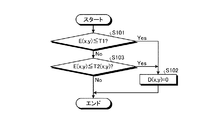
ついで、エッジ除外部106は、エッジのノイズ除去のためのエッジ細線化処理を行う(ステップS303)。具体的な処理の流れを図6を用いて説明する。図6に示されるように、まず、エッジ除外部106は、ある座標(x,y)の画素を選択し、この画素P(x,y)の輝度勾配の強さであるE(x,y)が予め定められた所定の閾値T1(第3閾値に相当)以下であるか否かを判定する(ステップS101)。E(x,y)が予め定められた所定の閾値T1以下であると判定された場合(ステップS101:Yes)、エッジ除外部106は、P(x,y)の方向コードであるD(x,y)を0とする(ステップS102)。本実施形態においては、以降の処理で方向コードが「0」でないものをエッジとして認識して処理を行うため、方向コードを0とすることで、その画素がエッジとして除外されることとなる。なお、方向コードではなく、輝度勾配の強さE(x,y)に基づいて、以降の処理を行う場合は、E(x,y)を0とする処理を代わりに行ってもよい。
Next, the
一方、E(x,y)が予め定められた所定の閾値T1より大きいと判定された場合(ステップS101:No)、エッジ除外部106は、ついでE(x,y)が所定の閾値T2(x,y)以下であるか否かを判定する(ステップS103)。閾値T2は、輝度勾配の強さE(x,y)が勾配方向に沿って隣接する画素のうちで最大であるか否かを判定するための非最大抑制閾値であり、図7に示す式に基づき算出される。
On the other hand, when it is determined that E (x, y) is larger than the predetermined threshold T1 (step S101: No), the
図7に示されるように、方向コードがD(x,y)=1の場合は、閾値T2はMax{E(x,y+1),E(x,y−1)}により求められる。Max{A,B}は、A,Bのうち大きい値を取得する関数である。この式の場合、上下に隣接する画像のうち輝度勾配の強さが大きい方の値が取得される。方向コードがD(x,y)=2の場合は、閾値T2はMax{E(x+1,y+1),E(x−1,y−1)}により求められる。この式の場合、右下と左上方向に隣接する画像のうち輝度勾配の強さが大きい方の値が取得される。方向コードがD(x,y)=3の場合は、閾値T2はMax{E(x+1,y),E(x−1,y)}により求められる。この式の場合、左右方向に隣接する画像のうち輝度勾配の強さが大きい方の値が取得される。方向コードがD(x,y)=4の場合は、閾値T2はMax{E(x−1,y+1),E(x+1,y−1)}により求められる。この式の場合、左下と右上方向に隣接する画像のうち輝度勾配の強さが大きい方の値が取得される。 As shown in FIG. 7, when the direction code is D (x, y) = 1, the threshold T2 is obtained by Max {E (x, y + 1), E (x, y-1)}. Max {A, B} is a function for obtaining a larger value of A and B. In the case of this expression, a value having a larger intensity gradient is acquired from the vertically adjacent images. When the direction code is D (x, y) = 2, the threshold T2 is obtained by Max {E (x + 1, y + 1), E (x-1, y-1)}. In the case of this expression, a value having a larger intensity gradient is acquired from images adjacent in the lower right and upper left directions. When the direction code is D (x, y) = 3, the threshold value T2 is obtained by Max {E (x + 1, y), E (x-1, y)}. In the case of this expression, a value having a larger intensity gradient among images adjacent in the left-right direction is acquired. When the direction code is D (x, y) = 4, the threshold value T2 is obtained by Max {E (x-1, y + 1), E (x + 1, y-1)}. In the case of this expression, a value having a larger intensity gradient is acquired from images adjacent in the lower left and upper right directions.
エッジ除外部106は、上述のように算出された閾値T2を用いて判定を行い、E(x,y)が所定の閾値T2(x,y)以下である場合(ステップS103:Yes)、エッジ除外部106は、P(x,y)の方向コードであるD(x,y)を0とする(ステップS102)。一方、E(x,y)が所定の閾値T2(x,y)より大きい場合(ステップS103:No)、エッジ除外部106は処理を行わず処理を終了する。以上の処理を通じて、画素のエッジが細線化される。図8は、エッジ細線化処理が実施された後の、1つのパターン要素である円周辺の画素に割り当てられた方向コードを示した図である。
The
図8に示されるように、各画素のうち、輝度勾配の強さの小さい画素や、エッジの勾配方向において最大値となっていない画素は、方向コードが0となるため、円形の輪郭に沿って、「0」でない方向コードを割り当てられた幅1のエッジの線分が示されるようになる。
As shown in FIG. 8, among the pixels, a pixel with a small intensity gradient or a pixel that does not have the maximum value in the edge gradient direction has a direction code of 0, and therefore follows a circular outline. Thus, the line segment of the edge of
ついで、評価部102は、方向コードが割り当てられた画素のうち、方向コードに応じて画素ごとに定められる閾値Q(x,y)(第1閾値に相当)を決定する図地分離閾値決定処理を行う(図3、ステップS311)。図地分離閾値とは、画素が前景画素(図画素)と、背景画素(地画素)とのいずれであるかを判別するための閾値である。図8において、方向コードが0でない画素は、輝度勾配方向において輝度勾配の強度が最大となっていることから、勾配方向において隣接する2つの画素同士は画素値P(x,y)が大きく乖離しており、一方が前景画素、他方が背景画素となっている。したがって、本実施形態では、隣接する2つの画素の画素値P(x,y)の中間値を図地分離閾値とすることで、画素が背景画素と前景画素のいずれであるかを判別できるようにする。図9は、方向コードごとの図地分離閾値を算出する式をまとめた表である。
Next, the
図9に示されるように、方向コードD(x,y)が1の画素P(x,y)の場合、図地分離閾値Q(x,y)は、{P(x,y−1)+P(x,y+1)}/2で示される、上下の隣接する2つの画素の中間輝度となる。また、方向コードD(x,y)が2の画素P(x,y)の場合、図地分離閾値Q(x,y)は、{P(x−1,y−1)+P(x+1,y+1)}/2で示される、左上と右下の隣接する2つの画素の中間輝度となる。また、方向コードD(x,y)が3の画素P(x,y)の場合、図地分離閾値Q(x,y)は、{P(x−1,y)+P(x+1,y)}/2で示される、左と右の隣接する2つの画素の中間輝度となる。また、方向コードD(x,y)が4の画素P(x,y)の場合、図地分離閾値Q(x,y)は、{P(x+1,y−1)+P(x−1,y+1)}/2で示される、左下と右上の隣接する2つの画素の中間輝度となる。 As shown in FIG. 9, when the direction code D (x, y) is a pixel P (x, y) of 1, the figure-ground separation threshold Q (x, y) is {P (x, y-1) This is an intermediate luminance between two adjacent pixels above and below, represented by + P (x, y + 1)} / 2. When the direction code D (x, y) is a pixel P (x, y) of 2, the figure-ground separation threshold Q (x, y) is {P (x−1, y−1) + P (x + 1, y + 1)} / 2, which is an intermediate luminance between two adjacent pixels at the upper left and lower right. When the direction code D (x, y) is 3 pixels P (x, y), the figure-ground separation threshold Q (x, y) is {P (x-1, y) + P (x + 1, y). } / 2, which is an intermediate luminance between two adjacent pixels on the left and right. When the direction code D (x, y) is 4 pixels P (x, y), the figure-ground separation threshold Q (x, y) is {P (x + 1, y−1) + P (x−1, y + 1)} / 2, which is an intermediate luminance between two adjacent pixels on the lower left and upper right.
続いて、評価部102は、画素P(x,y)が前景画素か、背景画素かを判定するための値である図地評価値C(x,y)を算出する図地評価値算出処理を行う(図3:ステップS312)。以下、上述のように算出された図地分離閾値Q(x,y)を用いて、画素P(x,y)が前景画素か、背景画素かを判定するための値である図地評価値C(x,y)を算出する処理の流れを図10により説明する。図10に示されるように、まず評価部102は、図地評価値C(x,y)を初期化する(ステップS201)。また、評価部102は、注目画素(方向コードが0ではない画素のうちの1つ)を選択するポインタであるnの値を1に初期化するとともに、rの値にパターン要素である円の半径を代入する。本実施形態においては、画素P(x,y)を評価する際に、画素P(x,y)だけではなく、その近傍領域までを含めた範囲を対象に、図地分離閾値Q(x,y)による評価を行う。
Subsequently, the
図8で示した、パターン要素の輪郭付近だけが前景画素か背景画素であるかの評価を受けた場合、パターン要素の中心部は評価を受けられないことになってしまう。したがってパターン要素サイズ(ここでは円半径)を反映した領域を近傍領域とすることが望ましい。本実施形態では、パターン要素である円の半径rを用い、始点:(x0−r,y0−r)〜終点:(x0+r,y0+r)で定められる矩形領域を近傍領域とする。なお近傍領域の設定は、注目画素を中心として上下左右に円の半径rに等しい広がりを持つ矩形領域に限定されるものではない。例えば円と同じ面積となるような一辺長さ(=SQRT(π)*r)を持つ矩形領域や、1.5×rに等しい半径を持つ円形領域等を近傍領域と設定することができる。 When the evaluation is made as to whether only the vicinity of the contour of the pattern element shown in FIG. 8 is a foreground pixel or a background pixel, the central part of the pattern element cannot be evaluated. Therefore, it is desirable that the area reflecting the pattern element size (here, the circle radius) be a neighboring area. In the present embodiment, a radius r of a circle that is a pattern element is used, and a rectangular area defined by a start point: (x0-r, y0-r) to an end point: (x0 + r, y0 + r) is set as a neighboring area. The setting of the neighborhood area is not limited to a rectangular area having a spread equal to the radius r of the circle in the vertical and horizontal directions around the target pixel. For example, a rectangular region having a side length (= SQRT (π) * r) that has the same area as a circle, a circular region having a radius equal to 1.5 × r, or the like can be set as the neighboring region.
評価部102は、注目画素をn番目の画素に設定する(ステップS202)。そして、評価部102は、代表座標のY座標を注目画素のy0からrを減算した座標とするとともに(ステップS203)、代表座標のX座標を注目画素のx0からrを減算した座標とする(ステップS204)。そして、評価部102は、近傍領域に属する画素の画素値P(x,y)が図地分離閾値Q(x0,y0)よりも小さいか否かを判定する(ステップS205)。画素の画素値P(x,y)が図地分離閾値Q(x0,y0)よりも小さい(暗い)と判定された場合(ステップS205:Yes)、画素P(x,y)と対応する図地評価値C(x,y)が1カウントアップされる(ステップS206)。画素値P(x,y)が図地分離閾値Q(x0,y0)よりも大きい(明るい)と判定された場合(ステップS205:No)、ステップS206はスキップされる。
The
次いで、座標Xが近傍領域において最も大きいX座標であるx0+rであるか否かが判定される(ステップS207)。座標Xが近傍領域において最も大きいX座標であるx0+rでないと判定された場合(ステップS207:No)、評価部102はXを1加算して(ステップS208)、次の座標についての図地評価値C(x,y)を計測する。一方、座標Xが近傍領域において最も大きいX座標であるx0+rであると判定された場合(ステップS207:Yes)、座標Yが近傍領域において最も大きいY座標であるy0+rであるか否かが判定される(ステップS209)。座標yが近傍領域において最も大きいY座標であるy0+rでないと判定された場合(ステップS209:No)、評価部102はYを1加算して(ステップS210)、ステップS204から、次の座標についての図地評価値C(x,y)を計測する。一方、座標Yが近傍領域において最も大きいY座標であるy0+rであると判定された場合(ステップS209:Yes)、注目画素がまだ残っているか否かの判定が行われる(ステップS211)。注目画素がまだ残っていると判定された場合(ステップS211:Yes)、評価部102はnを1加算して(ステップS212)、ステップS202からの処理を繰り返す。一方、注目画素が残っていないと判定された場合(ステップS211:No)、処理は終了する。
Next, it is determined whether or not the coordinate X is x0 + r which is the largest X coordinate in the vicinity region (step S207). When it is determined that the coordinate X is not x0 + r which is the largest X coordinate in the vicinity region (step S207: No), the
図11は、以上の処理を経てパターン要素を構成する画素毎に図地評価値C(x,y)が割り当てられた状態を示した図である。このように、各々の円の内部領域にある画素に対する図地評価値C(x,y)が高くなる。円の内部領域側においては、方向コードが0ではないそれぞれの画素において、近傍領域の範囲に入ることから、結果として評価値の値が高くなるためである。評価部102は、各画素に割り当てた図地評価値C(x,y)の値を図地評価値バッファ123に記憶する。
FIG. 11 is a diagram showing a state in which the figure-ground evaluation value C (x, y) is assigned to each pixel constituting the pattern element through the above processing. Thus, the figure-ground evaluation value C (x, y) for the pixels in the inner area of each circle is increased. This is because, on the inner area side of the circle, each pixel whose direction code is not 0 enters the range of the neighboring area, and as a result, the evaluation value increases. The
次いで、二値化処理部103は、二値化処理を実施する(図3:ステップS321)。二値化処理部103は、図地評価値バッファ123に記憶された図地評価値C(x,y)とあらかじめ定められた正の閾値T3(第2閾値に相当)を用いて、次式にしたがって二値画像B(x,y)を算出する。
Next, the
C(x,y)<T3 ならば B(x,y)=0
C(x,y)≧T3 ならば B(x,y)=1
If C (x, y) <T3, B (x, y) = 0
If C (x, y) ≧ T3, B (x, y) = 1
閾値T3=4を用いて二値化した結果を図12に示す。以下ではB(x,y)=0にあたる画素を「背景画素」、B(x,y)=1にあたる画素を「前景画素」と呼ぶ。図12に示されるように、パターン要素の円形にそって、前景画素と認識される画素が配置されている。二値化したB(x,y)の値は、座標とともに二値画像バッファ124に記憶される。
The result of binarization using threshold value T3 = 4 is shown in FIG. Hereinafter, a pixel corresponding to B (x, y) = 0 is referred to as a “background pixel”, and a pixel corresponding to B (x, y) = 1 is referred to as a “foreground pixel”. As shown in FIG. 12, pixels that are recognized as foreground pixels are arranged along the circle of the pattern element. The binarized B (x, y) value is stored in the
続いて、連結成分生成部104は、二値画像B(x,y)に対して上下左右に隣り合う図画素同士を1つのグループとして統合するラベリング処理を行う(図3:ステップS331)。二値画像に対するラベリング処理としては、既存のラベリング方法を用いる。本実施形態においては、図12において、「1」で示される画素が、全て連結されて1つの円形のパターン要素の形状に対応する連結成分が生成される。ラベリングによって各々固有のラベルを付けられた図画素連結成分が得られる。図13に示すように、個々の図画素連結成分が1つの円に対応すると考えられるので、第i番目の図画素連結成分を第i番目のパターン要素(円)として出力する。出力されるラベリング結果は、ラベリング結果バッファ125に記憶される。その際、1つの円の代表座標(xc,yc)として、本実施形態ではその円に対応する図画素連結成分の外接矩形の始点:(xs,ys)と終点:(xe,ye)との中点を用いることとする。代表座標(xc,yc)は以下の式により算出される。
Subsequently, the connected
xc=(xs+xe)/2
yc=(ys+ye)/2
xc = (xs + xe) / 2
yc = (ys + ye) / 2
そして、パターン変換部105は、生成された画素連結成分をそれぞれパターン要素として変換し、パターン要素により構成される校正用のパターン画像が取得される。こうして1枚の入力画像をもとに、パターン画像を構成するパターン要素の円が画素連結成分として抽出され、それぞれの円の代表座標が取得される。このようにして取得された構成用のパターン画像に基づいて、理想的なパターン画像との間で歪みを算出し、投影を補正するための処理が実施される。歪み補正のための処理は既存の方法を用いることができる。 Then, the pattern conversion unit 105 converts the generated pixel connected components as pattern elements, respectively, and obtains a calibration pattern image including the pattern elements. Thus, based on one input image, a circle of pattern elements constituting the pattern image is extracted as a pixel connection component, and representative coordinates of each circle are acquired. Based on the pattern image for the configuration obtained in this way, a distortion is calculated between the ideal pattern image and a process for correcting the projection is performed. An existing method can be used for processing for distortion correction.
以上に示したパターン処理装置1においては、パターン要素を構成する画素を輝度の絶対値ではなく、パターンの背景画素と、前景画素との間の相対的な輝度の差に基づくエッジの勾配強度に基づいて二値化処理を行う。このため、照明ムラなどにより、輝度の絶対値が変化して、適切に校正用のパターン画像を取得できないといった問題が発生しにくくなり、高い精度で特徴点の抽出を行うことができる。
In the
また、パターン画像の取得のために、照明を消したり、複数の画像を投影したりといったことも必要ないため、パターン取得のための手間もかからない。 Further, since it is not necessary to turn off the illumination or project a plurality of images in order to acquire the pattern image, it does not take time and effort to acquire the pattern.
また、エッジ画素のうち、ノイズや極大となっていない画素を除外するようにしたため、より精度の高い抽出が可能となる。さらには、近傍領域を設定する際に、パターン要素の円形の半径を近傍領域の範囲を設定する際の値として用いたため、エッジ画素を基点としてパターン要素を構成する画素を適切に評価範囲に含めることができるようになる。 In addition, since pixels that are not noise or local maximum are excluded from the edge pixels, more accurate extraction is possible. Furthermore, since the circular radius of the pattern element was used as a value when setting the range of the neighborhood area when setting the neighborhood area, the pixels constituting the pattern element from the edge pixel as the base point are appropriately included in the evaluation range. Will be able to.
(第2の実施形態)
パターン処理装置の第2の実施形態について説明する。本実施形態においては、ラベリング処理により得られた図画素連結成分の形状特徴が予め定められたパターン要素の特徴と一致するかを判定する処理を行う。具体的には、図画連結成分の外接矩形の幅w、及び高さhに対し、閾値T4、T5、及びT6を用いて、次式による基準を満たすかどうかをチェックする(T4<T5、かつT6>1)。
(Second Embodiment)
A second embodiment of the pattern processing apparatus will be described. In the present embodiment, a process is performed to determine whether or not the shape feature of the figure pixel connected component obtained by the labeling process matches a predetermined pattern element feature. Specifically, the thresholds T4, T5, and T6 are used for the width w and the height h of the circumscribed rectangle of the graphic connected component to check whether or not the following formula is satisfied (T4 <T5, and T6> 1).
(1)T4≦w≦T5 かつ T4≦h≦T5
(2)1/T6≦w/h≦T6
(1) T4 ≦ w ≦ T5 and T4 ≦ h ≦ T5
(2) 1 / T6 ≦ w / h ≦ T6
閾値T4、及びT5は、図画連結成分の外接矩形の幅、及び高さの最小値、及び最大値を示す値である。本実施形態では、パターン要素が円形であるため、幅と高さの最大値は同じ値である。また、閾値T4、及びT5は、パターン要素の予め設定されたサイズに基づいて設定される。また、閾値T6は、外接矩形のアスペクト比がT6:1〜1:T6以内で方形に近い形状となるように設定されている。これらの図画素連結成分の形状特徴は、元となるパターン要素の形状によって異なることから閾値の値は形状に応じて適宜設定される。 The threshold values T4 and T5 are values indicating the minimum value and the maximum value of the width and height of the circumscribed rectangle of the graphic connected component. In the present embodiment, since the pattern elements are circular, the maximum values of the width and the height are the same value. The threshold values T4 and T5 are set based on a preset size of the pattern element. The threshold T6 is set so that the circumscribed rectangle has an aspect ratio close to a square within T6: 1 to 1: T6. Since the shape characteristics of these figure pixel connected components differ depending on the shape of the original pattern element, the threshold value is appropriately set according to the shape.
条件(1)(2)のうち少なくとも1つが満たされないとき、形状特徴を満たさない図画素連結成分は校正用のパターン画像からは除外される。結果として、図14−1〜図14−3において示されたような形状の図画素連結成分は除去される。この図画素連結成分は、例えばスクリーン枠やプロジェクタ本体等といった背景オブジェクトの写りこみや撮像過程で入りこむ微小なノイズに由来するものであり、本来抽出すべきパターン要素である円に対応する図画素連結成分だけを取得することができる。 When at least one of the conditions (1) and (2) is not satisfied, the figure pixel connected component that does not satisfy the shape feature is excluded from the pattern image for calibration. As a result, the diagram pixel connected component having the shape as shown in FIGS. 14-1 to 14-3 is removed. This figure pixel connection component is derived from the reflection of a background object such as a screen frame or a projector main body or a minute noise that enters during the imaging process, and the figure pixel connection component corresponding to a circle that is a pattern element to be originally extracted. Only ingredients can be obtained.
(第3の実施形態)
第1の実施形態では抽出されたパターン要素の代表座標(xc,yc)として、その円に対応する図画素連結成分の外接矩形の始点:(xs,ys)と終点:(xe,ye)との中点を用いたが、本実施形態では図画素連結成分を構成する図画素の重心を用いる。
(Third embodiment)
In the first embodiment, as the representative coordinates (xc, yc) of the extracted pattern element, the circumscribed rectangle start point (xs, ys) and end point (xe, ye) of the figure pixel connected component corresponding to the circle are However, in this embodiment, the center of gravity of the diagram pixels constituting the diagram pixel connected component is used.
すなわち、注目する図画素連結成分を構成するN個の図画素のうち、第i番目の座標を(xi,yi)とすると、
もし撮像時に手ブレが発生したり、スクリーンの汚れからくるノイズが混入したりして、例えば図15のように図画素連結成分が細長いひげ状の突起を持ってしまった場合、外接矩形の中点は突起の存在に敏感に反応してしまい、突起のない理想的な場合に比べて中点の位置がかなりずれてしまう。 If camera shake occurs at the time of imaging, or noise from the screen is mixed, for example, as shown in FIG. 15, the pixel connected component has a long and thin beard-like projection, the inside of the circumscribed rectangle The point reacts sensitively to the presence of the protrusion, and the position of the midpoint is considerably deviated from the ideal case where there is no protrusion.
一方、重心については図画素総数Nが十分大きければひげ状突起の画素による重心を算出する際の影響度は小さいため、突起のない理想的な場合とほぼ同じ位置が得られるようになる。 On the other hand, if the total number N of the figure pixels is sufficiently large with respect to the center of gravity, the degree of influence when calculating the center of gravity by the pixels of the whiskers is small, so that the same position as in an ideal case without protrusions can be obtained.
なお、パターン処理にかかるプログラムはコンピュータ上のプログラムに実行させることもできる。図16は一般的なコンピュータの構成を示すハードウェア構成図であり、CPU201、ハードディスク202、ディスプレイ203、通信装置204、CD−ROMドライブ205、メモリ206、及びキーボード/マウス207を備えている。例えば、CD−ROM等の記録媒体に記録されたパターン処理プログラムを、CD−ROMドライブ205を通じて読み込み、実行時にはメモリ206上にロードされ、CPU201からの指令によってプログラムの処理ステップが順次実行されるようにしてもよい。入力画像は、あらかじめハードディスク202上に蓄えられるか、または実行時に図示しないデジタルカメラを通じて取り込まれた後、メモリ206上にロードされて参照される。パターン抽出の結果はメモリ206に保存された後、利用の必要に応じてメモリ206から読み出され、ハードディスク202に書き出されたり、ディスプレイ203に出力されたり、通信装置204を介してネットワーク上へ送出されたり、あるいは図示しないプリンタを通じて紙上に印字されたりする。
The program for pattern processing can be executed by a program on a computer. FIG. 16 is a hardware configuration diagram showing the configuration of a general computer, which includes a
また、上記の実施形態においては、エッジ勾配のある注目画素の近傍領域に含まれる画素の画素値が所定の閾値を超える場合に図地評価値を加算することとしたが、画素値が所定の閾値よりも低い場合に、図地評価値を減算するようにすることもできる。すなわち、近傍領域に含まれる画素を絶対値ではなく数合的に判断して算出できる評価値を用いることができれば、二値化をより高い精度で行うことができるようになる。 In the above embodiment, the figure-ground evaluation value is added when the pixel value of the pixel included in the vicinity region of the target pixel having the edge gradient exceeds the predetermined threshold value. If it is lower than the threshold value, the figure-ground evaluation value may be subtracted. That is, binarization can be performed with higher accuracy if an evaluation value that can be calculated by numerically determining the pixels included in the neighborhood region instead of an absolute value can be used.
1 パターン処理装置
100 入力部
101 抽出部
102 評価部
103 二値化処理部
104 連結成分生成部
105 パターン変換部
106 エッジ除外部
120 記憶部
121 入力画像バッファ
122 エッジ方向コードバッファ
123 図地評価値バッファ
124 二値画像バッファ
125 ラベリング結果バッファ
202 ハードディスク
203 ディスプレイ
204 通信装置
205 CD−ROMドライブ
206 メモリ
207 キーボード/マウス
DESCRIPTION OF
Claims (10)
抽出された前記エッジ画素のうち、前記エッジ強度が第3閾値未満の画素を除去するとともに、前記エッジ画素のエッジ強度が勾配方向に沿って隣接する画素のうちで最大か否かを判定し、最大でない前記エッジ画素を除外するエッジ除外部と、
前記エッジ除外部における処理後の前記エッジ画素の近傍領域に含まれる近傍画素の輝度と第1閾値の比較結果に応じて、前記近傍画素の種類を判定するための評価値を求める評価部と、
前記評価値を、第2閾値と比較することにより、前記近傍画素の種類を判定する判定部と、
を備えることを特徴とするパターン処理装置。 An extraction unit that extracts edge pixels from input image data in which pattern elements are arranged ;
Among the extracted edge pixels, the pixels whose edge intensity is less than a third threshold are removed, and it is determined whether the edge intensity of the edge pixel is the maximum among adjacent pixels along the gradient direction, An edge exclusion unit that excludes the edge pixels that are not maximum;
An evaluation unit for obtaining an evaluation value for determining the type of the neighboring pixel according to a comparison result between the luminance of the neighboring pixel and the first threshold included in the neighboring region of the edge pixel after processing in the edge exclusion unit ;
A determination unit that determines the type of the neighboring pixel by comparing the evaluation value with a second threshold;
A pattern processing apparatus comprising:
ことを特徴とする請求項1に記載のパターン処理装置。 Among the pixels determined to be foreground pixels, the pixel further includes an extraction unit that connects adjacent pixels and extracts them as a connected component.
The pattern processing apparatus according to claim 1.
ことを特徴とする請求項1または2に記載のパターン処理装置。 The evaluation unit, pattern processing according to the range that is calculated using a preset size of the pattern elements the edge pixel as a base point, to claim 1 or 2, characterized in that to set as the neighboring region apparatus.
ことを特徴とする請求項1または2に記載のパターン処理装置。 The evaluation unit, the edge pixel, and in a gradient direction of the edge intensity intermediate value of the respective pixel values of pixels adjacent to the edge pixel to claim 1 or 2, characterized in that calculated as the first threshold value The pattern processing apparatus as described.
前記重心の座標を前記パターン要素の代表座標として設定するパターン変換部を更に備える
ことを特徴とする請求項2に記載のパターン処理装置。 The extraction unit calculates the coordinates of the center of gravity of the connected component,
The pattern processing apparatus according to claim 2, further comprising: a pattern conversion unit that sets the coordinates of the center of gravity as the representative coordinates of the pattern element.
ことを特徴とする請求項2に記載のパターン処理装置。 The extraction unit calculates an edge strength for each pixel after converting the luminance of the pixel of the pattern element in the input image data into a grayscale image having a range of 0 (black) to 255 (white). The pattern processing apparatus according to claim 2, wherein edge pixels are extracted.
抽出された前記エッジ画素のうち、前記エッジ強度が第3閾値未満の画素を除去するとともに、前記エッジ画素のエッジ強度が前記勾配方向に沿って隣接する画素のうちで最大か否かを判定し、最大でない前記エッジ画素を除外するエッジ除外ステップと、
前記エッジ除外ステップにおける処理後の前記エッジ画素の近傍領域に含まれる近傍画素の輝度と第1閾値の比較結果に応じて、前記近傍画素の種類を判定するための評価値を求める評価ステップと、
前記評価値を、第2閾値と比較することにより、前記近傍画素の種類を判定する判定ステップと、
を含むことを特徴とするパターン処理方法。 An extraction step of extracting edge pixels from input image data in which pattern elements are arranged ;
Among the extracted edge pixels, the pixels whose edge intensity is less than a third threshold are removed, and it is determined whether the edge intensity of the edge pixel is the maximum among the adjacent pixels along the gradient direction. An edge exclusion step of excluding the edge pixels that are not maximal;
An evaluation step for obtaining an evaluation value for determining the type of the neighboring pixel according to a comparison result between the luminance of the neighboring pixel included in the neighboring region of the edge pixel after the processing in the edge exclusion step and the first threshold value;
A determination step of determining the type of the neighboring pixel by comparing the evaluation value with a second threshold;
A pattern processing method comprising:
ことを特徴とする請求項7に記載のパターン処理方法。 An extraction step of connecting adjacent pixels among the pixels determined to be foreground pixels and extracting them as connected components;
The pattern processing method according to claim 7 .
ことを特徴とする請求項7または8に記載のパターン処理方法。 9. The pattern processing according to claim 7 , wherein, in the evaluation step, a range calculated using a preset size of the pattern element with the edge pixel as a base point is set as the neighborhood region. Method.
パターン要素が配置された入力画像データからエッジ画素を抽出する抽出ステップと、
抽出された前記エッジ画素のうち、前記エッジ強度が第3閾値未満の画素を除去するとともに、前記エッジ画素のエッジ強度が前記勾配方向に沿って隣接する画素のうちで最大か否かを判定し、最大でない前記エッジ画素を除外するエッジ除外ステップと、
前記エッジ除外ステップにおける処理後の前記エッジ画素の近傍領域に含まれる近傍画素の輝度と第1閾値の比較結果に応じて、前記近傍画素の種類を判定するための評価値を求める評価ステップと、
前記評価値を、第2閾値と比較することにより、前記近傍画素の種類を判定する判定ステップと、
を実行させるためのパターン処理プログラム。 On the computer,
An extraction step of extracting edge pixels from input image data in which pattern elements are arranged ;
Among the extracted edge pixels, the pixels whose edge intensity is less than a third threshold are removed, and it is determined whether the edge intensity of the edge pixel is the maximum among the adjacent pixels along the gradient direction. An edge exclusion step of excluding the edge pixels that are not maximal;
An evaluation step for obtaining an evaluation value for determining the type of the neighboring pixel according to a comparison result between the luminance of the neighboring pixel included in the neighboring region of the edge pixel after the processing in the edge exclusion step and the first threshold value;
A determination step of determining the type of the neighboring pixel by comparing the evaluation value with a second threshold;
Pattern processing program to execute.
Priority Applications (4)
| Application Number | Priority Date | Filing Date | Title |
|---|---|---|---|
| JP2013054193A JP6115214B2 (en) | 2012-05-22 | 2013-03-15 | Pattern processing apparatus, pattern processing method, and pattern processing program |
| US13/896,912 US9123123B2 (en) | 2012-05-22 | 2013-05-17 | Pattern processing device, pattern processing method, and pattern processing program |
| CN201310313418.3A CN103428511B (en) | 2012-05-22 | 2013-05-21 | Image disposal device and pattern treatment method |
| US14/691,747 US9454824B2 (en) | 2012-05-22 | 2015-04-21 | Pattern processing device, pattern processing method, and pattern processing program |
Applications Claiming Priority (5)
| Application Number | Priority Date | Filing Date | Title |
|---|---|---|---|
| JP2012116992 | 2012-05-22 | ||
| JP2012116992 | 2012-05-22 | ||
| JP2013043522 | 2013-03-05 | ||
| JP2013043522 | 2013-03-05 | ||
| JP2013054193A JP6115214B2 (en) | 2012-05-22 | 2013-03-15 | Pattern processing apparatus, pattern processing method, and pattern processing program |
Publications (3)
| Publication Number | Publication Date |
|---|---|
| JP2014197243A JP2014197243A (en) | 2014-10-16 |
| JP2014197243A5 JP2014197243A5 (en) | 2016-03-03 |
| JP6115214B2 true JP6115214B2 (en) | 2017-04-19 |
Family
ID=49621645
Family Applications (1)
| Application Number | Title | Priority Date | Filing Date |
|---|---|---|---|
| JP2013054193A Active JP6115214B2 (en) | 2012-05-22 | 2013-03-15 | Pattern processing apparatus, pattern processing method, and pattern processing program |
Country Status (3)
| Country | Link |
|---|---|
| US (2) | US9123123B2 (en) |
| JP (1) | JP6115214B2 (en) |
| CN (1) | CN103428511B (en) |
Families Citing this family (10)
| Publication number | Priority date | Publication date | Assignee | Title |
|---|---|---|---|---|
| JP5924020B2 (en) * | 2012-02-16 | 2016-05-25 | セイコーエプソン株式会社 | Projector and projector control method |
| JP6115214B2 (en) * | 2012-05-22 | 2017-04-19 | 株式会社リコー | Pattern processing apparatus, pattern processing method, and pattern processing program |
| JP6316010B2 (en) * | 2014-01-30 | 2018-04-25 | キヤノン株式会社 | Image processing apparatus and image processing method |
| JP2015204548A (en) * | 2014-04-15 | 2015-11-16 | 株式会社リコー | image projection system |
| CN105323419B (en) * | 2014-07-25 | 2018-07-31 | 能晶科技股份有限公司 | The method for generating bearing images |
| JP6657570B2 (en) * | 2015-03-02 | 2020-03-04 | セイコーエプソン株式会社 | Image processing device, display device, and control method for image processing device |
| US9961283B2 (en) * | 2016-09-07 | 2018-05-01 | Essential Products, Inc. | Color reconstruction |
| CN106803258A (en) * | 2017-01-13 | 2017-06-06 | 深圳怡化电脑股份有限公司 | A kind of image processing method and device |
| CN110753213B (en) * | 2018-11-07 | 2022-02-01 | 成都极米科技股份有限公司 | Trapezoidal correction method and system, projection equipment and storage medium |
| CN116912133B (en) * | 2023-09-12 | 2023-12-19 | 深圳市瑞沃德生命科技有限公司 | Gradient direction correction method and device |
Family Cites Families (30)
| Publication number | Priority date | Publication date | Assignee | Title |
|---|---|---|---|---|
| US4995716A (en) * | 1989-03-09 | 1991-02-26 | Par Technology Corporation | Method and apparatus for obtaining the topography of an object |
| JPH07225847A (en) * | 1994-02-10 | 1995-08-22 | Fujitsu General Ltd | Image extracting method |
| JPH10191020A (en) * | 1996-12-20 | 1998-07-21 | Canon Inc | Object image segmenting method and device |
| JPH1173509A (en) * | 1997-08-29 | 1999-03-16 | Advantest Corp | Device and method for recognizing image information |
| JP3830350B2 (en) * | 2001-01-31 | 2006-10-04 | 株式会社リコー | Color image processing method, color image processing apparatus, program, and recording medium |
| JP4049296B2 (en) * | 2001-04-11 | 2008-02-20 | 株式会社リコー | Color image information processing method, program used to execute the method, and color image information processing apparatus |
| GB0227160D0 (en) * | 2002-11-21 | 2002-12-24 | Qinetiq Ltd | Histological assessment of pleomorphism |
| EP1670257B1 (en) * | 2004-12-10 | 2018-09-26 | Ricoh Company, Ltd. | Compressing a mutlivalue image with control of memory space requirement |
| EP1686536B1 (en) * | 2005-02-01 | 2012-07-25 | Ricoh Company, Ltd. | Applying edge enhancement based on image characteristics |
| JP2007172397A (en) * | 2005-12-22 | 2007-07-05 | Seiko Epson Corp | Edge gradient detection method, stain defect detection method, edge gradient detection device and stain defect detection device |
| JP4664838B2 (en) * | 2006-03-02 | 2011-04-06 | 日本放送協会 | Video object tracking device and video object tracking program |
| US8106968B1 (en) * | 2008-02-20 | 2012-01-31 | Cognitech, Inc. | System and method for pattern detection and camera calibration |
| CN101256157B (en) | 2008-03-26 | 2010-06-02 | 广州中国科学院工业技术研究院 | Method and apparatus for testing surface defect |
| JP2010004111A (en) * | 2008-06-18 | 2010-01-07 | Nec Electronics Corp | Image processor, image processing method, and program |
| JP5256899B2 (en) | 2008-07-18 | 2013-08-07 | セイコーエプソン株式会社 | Image correction apparatus, image correction method, projector and projection system |
| JP5116640B2 (en) * | 2008-11-15 | 2013-01-09 | 株式会社キーエンス | Image processing apparatus, image processing program, and computer-readable recording medium having detection candidate neighborhood exclusion function |
| US8467089B2 (en) * | 2008-11-24 | 2013-06-18 | Xerox Corporation | Systems and methods for line width control and pixel retagging |
| JP2010183416A (en) * | 2009-02-06 | 2010-08-19 | Ricoh Co Ltd | Image processing apparatus and method, program, and recording medium |
| US8411986B2 (en) * | 2009-04-13 | 2013-04-02 | Flashfoto, Inc. | Systems and methods for segmenation by removal of monochromatic background with limitied intensity variations |
| EP2446420B1 (en) * | 2009-06-24 | 2022-03-23 | Nokia Technologies Oy | Device and method for processing digital images captured by a binary image sensor |
| JP5454075B2 (en) * | 2009-10-20 | 2014-03-26 | ソニー株式会社 | Image processing apparatus, image processing method, and program |
| TWI513695B (en) * | 2009-10-27 | 2015-12-21 | Merck Sharp & Dohme | (1,1,1,3,3,3-hexafluoro-2-hydroxypropan-2-yl)phenyl derivatives |
| DE102009046114B4 (en) | 2009-10-28 | 2011-09-01 | Fraunhofer-Gesellschaft zur Förderung der angewandten Forschung e.V. | Method and apparatus for generating a calibrated projection |
| CN101814139B (en) | 2010-04-14 | 2012-02-29 | 华中科技大学 | Raindrop identifying method |
| KR101051459B1 (en) * | 2010-05-31 | 2011-07-22 | 한양대학교 산학협력단 | Apparatus and method for extracting edges of an image |
| CN102136068B (en) | 2011-03-31 | 2012-11-21 | 中国科学院半导体研究所 | Average grey-based method for extracting effective information region of range gating image |
| JP6102088B2 (en) * | 2011-09-01 | 2017-03-29 | 株式会社リコー | Image projection device, image processing device, image projection method, program for image projection method, and recording medium recording the program |
| JP6115214B2 (en) * | 2012-05-22 | 2017-04-19 | 株式会社リコー | Pattern processing apparatus, pattern processing method, and pattern processing program |
| JP2014179698A (en) * | 2013-03-13 | 2014-09-25 | Ricoh Co Ltd | Projector and control method of projector, and program of control method and recording medium with program recorded thereon |
| KR20160034847A (en) * | 2013-03-15 | 2016-03-30 | 스케일러블 디스플레이 테크놀로지스, 인크. | System and method for calibrating a display system using a short throw camera |
-
2013
- 2013-03-15 JP JP2013054193A patent/JP6115214B2/en active Active
- 2013-05-17 US US13/896,912 patent/US9123123B2/en not_active Expired - Fee Related
- 2013-05-21 CN CN201310313418.3A patent/CN103428511B/en not_active Expired - Fee Related
-
2015
- 2015-04-21 US US14/691,747 patent/US9454824B2/en active Active
Also Published As
| Publication number | Publication date |
|---|---|
| JP2014197243A (en) | 2014-10-16 |
| CN103428511A (en) | 2013-12-04 |
| US9454824B2 (en) | 2016-09-27 |
| US9123123B2 (en) | 2015-09-01 |
| US20150228083A1 (en) | 2015-08-13 |
| CN103428511B (en) | 2016-02-24 |
| US20130315489A1 (en) | 2013-11-28 |
Similar Documents
| Publication | Publication Date | Title |
|---|---|---|
| JP6115214B2 (en) | Pattern processing apparatus, pattern processing method, and pattern processing program | |
| AU2020101832A4 (en) | Image collection and depth image enhancement method and apparatus for kinect | |
| JP4154374B2 (en) | Pattern matching device and scanning electron microscope using the same | |
| CN107993263B (en) | Automatic calibration method for panoramic system, automobile, calibration device and storage medium | |
| US10430962B2 (en) | Three-dimensional shape measuring apparatus, three-dimensional shape measuring method, and storage medium that calculate a three-dimensional shape of an object by capturing images of the object from a plurality of directions | |
| JP2007531094A (en) | A method for extracting original data from images obtained from camera photographs | |
| CN112272292B (en) | Projection correction method, apparatus and storage medium | |
| US10078907B2 (en) | Distance measurement apparatus, distance measurement method, and storage medium | |
| JP2015060012A (en) | Image processing system, image processing device, image processing method and image processing program as well as display system | |
| JP2016151955A (en) | Image processing apparatus, imaging device, distance measuring device, and image processing method | |
| US10992913B2 (en) | Image processing apparatus, method, and storage medium storing program for transforming distortion of image projected by projection apparatus | |
| WO2014129018A1 (en) | Character recognition device, character recognition method, and recording medium | |
| JP2015109559A (en) | Image processing apparatus, and image processing method | |
| JP6232933B2 (en) | Radiation distortion correction apparatus, road environment recognition apparatus, radial distortion correction method and program | |
| CN113888509A (en) | Method, device and equipment for evaluating image definition and storage medium | |
| JP4801697B2 (en) | Image forming method, image forming apparatus, and computer program | |
| JP2005345290A (en) | Streak-like flaw detecting method and streak-like flaw detector | |
| US9581439B1 (en) | Image capture device with a calibration function and calibration method of an image capture device | |
| JP5955003B2 (en) | Image processing apparatus, image processing method, and program | |
| JP5754931B2 (en) | Image analysis apparatus, image analysis method, and program | |
| CN111091895A (en) | Breast image analysis method, system and non-transitory computer readable medium | |
| CN114727073B (en) | Image projection method and device, readable storage medium and electronic equipment | |
| JP4346620B2 (en) | Image processing apparatus, image processing method, and image processing program | |
| WO2023008509A1 (en) | Information processing program and information processing device | |
| JP6127620B2 (en) | Image processing apparatus and image processing method |
Legal Events
| Date | Code | Title | Description |
|---|---|---|---|
| A521 | Request for written amendment filed |
Free format text: JAPANESE INTERMEDIATE CODE: A523 Effective date: 20160115 |
|
| A621 | Written request for application examination |
Free format text: JAPANESE INTERMEDIATE CODE: A621 Effective date: 20160115 |
|
| A977 | Report on retrieval |
Free format text: JAPANESE INTERMEDIATE CODE: A971007 Effective date: 20161207 |
|
| A131 | Notification of reasons for refusal |
Free format text: JAPANESE INTERMEDIATE CODE: A131 Effective date: 20161220 |
|
| A521 | Request for written amendment filed |
Free format text: JAPANESE INTERMEDIATE CODE: A523 Effective date: 20170209 |
|
| TRDD | Decision of grant or rejection written | ||
| A01 | Written decision to grant a patent or to grant a registration (utility model) |
Free format text: JAPANESE INTERMEDIATE CODE: A01 Effective date: 20170221 |
|
| A61 | First payment of annual fees (during grant procedure) |
Free format text: JAPANESE INTERMEDIATE CODE: A61 Effective date: 20170306 |
|
| R151 | Written notification of patent or utility model registration |
Ref document number: 6115214 Country of ref document: JP Free format text: JAPANESE INTERMEDIATE CODE: R151 |