JP5955003B2 - Image processing apparatus, image processing method, and program - Google Patents
Image processing apparatus, image processing method, and program Download PDFInfo
- Publication number
- JP5955003B2 JP5955003B2 JP2012014145A JP2012014145A JP5955003B2 JP 5955003 B2 JP5955003 B2 JP 5955003B2 JP 2012014145 A JP2012014145 A JP 2012014145A JP 2012014145 A JP2012014145 A JP 2012014145A JP 5955003 B2 JP5955003 B2 JP 5955003B2
- Authority
- JP
- Japan
- Prior art keywords
- image
- projection
- images
- projected
- resolution
- Prior art date
- Legal status (The legal status is an assumption and is not a legal conclusion. Google has not performed a legal analysis and makes no representation as to the accuracy of the status listed.)
- Expired - Fee Related
Links
- 238000003672 processing method Methods 0.000 title claims 3
- 238000003384 imaging method Methods 0.000 claims description 100
- 238000000034 method Methods 0.000 claims description 43
- 238000001514 detection method Methods 0.000 claims description 10
- 238000004364 calculation method Methods 0.000 description 45
- 238000010586 diagram Methods 0.000 description 14
- 238000003702 image correction Methods 0.000 description 14
- 230000009466 transformation Effects 0.000 description 14
- 239000011159 matrix material Substances 0.000 description 4
- 230000001771 impaired effect Effects 0.000 description 2
- 230000004044 response Effects 0.000 description 2
- 230000015556 catabolic process Effects 0.000 description 1
- 238000006243 chemical reaction Methods 0.000 description 1
- 238000004590 computer program Methods 0.000 description 1
- 238000006731 degradation reaction Methods 0.000 description 1
- 230000006866 deterioration Effects 0.000 description 1
- 238000006073 displacement reaction Methods 0.000 description 1
- 238000011156 evaluation Methods 0.000 description 1
- 230000006870 function Effects 0.000 description 1
- 238000009499 grossing Methods 0.000 description 1
- 230000003287 optical effect Effects 0.000 description 1
- 230000035945 sensitivity Effects 0.000 description 1
- 238000002945 steepest descent method Methods 0.000 description 1
Images


Description
本発明は、複数の画像投影装置により単一画像を投影する画像投影システムに関する。 The present invention relates to an image projection system that projects a single image by a plurality of image projection apparatuses.
従来、複数のプロジェクタから互いに異なる投影領域に画像を投影し、これらの投影画像をつなぎ合わせることで単一の画像を表示する方法が提案されている(例えば、特許文献1、2)。特許文献1では、投影領域が重複するように配置した複数のプロジェクタから校正用パターンを投影し、それらを基に投影画像に幾何補正等の補正処理を施すことにより、各投影画像を簡便につなぎ合わせている。特許文献2では、重複領域の輝度を空間周波数に応じて補正することにより、重複領域の位置ずれによる解像感の劣化を抑制している。
Conventionally, there has been proposed a method of projecting images from a plurality of projectors to different projection areas, and displaying these images by connecting the projected images (for example,
しかしながら、特許文献1では、複数のプロジェクタによって構成される表示領域の画面解像度に対してカメラのセンサ画素数が小さい場合に、投影画像間の位置ずれが大きくなり重畳領域の解像感が損なわれるという課題があった。また、特許文献2では、そもそも位置ずれ自体を軽減できず、特に高周波成分を含む画像を表示した際に解像感が損なわれるという課題があった。
However, in
本発明に係る画像処理装置は、複数の投影手段から複数の画像を同時に投影することで1枚の画像を表示する投影システムにおいて、前記複数の投影手段に接続される画像処理装置であって、前記複数の投影手段から投影された複数の投影画像を、複数の撮像手段を有する撮像装置を用いて互いに異なる視点位置から撮像することによって得られた、複数の撮像画像を入力する入力手段と、前記複数の撮像画像における、それぞれが前記複数の投影画像のうちの一つに対応する画像領域である複数の投影領域の中で、対応する投影画像よりも画素数が少ない投影領域が存在する場合に、前記複数の撮像画像を用いて、少なくとも前記対応する投影画像よりも画素数が少ない投影領域の解像度が向上した高解像度画像を生成する生成手段と、前記複数の投影手段からの投影により表示される1枚の画像において、前記複数の投影手段から投影される各画像に対応する領域を示す領域情報を取得する取得手段と、前記領域情報が示す各領域において、位置合わせの為の基準点を設定する設定手段と、前記投影領域の中で、前記基準点に対応する点を検出する検出手段と、前記高解像度画像に基づいて、前記複数の投影手段から投影される画像を変形させるための変形パラメータであって、前記複数の投影手段から投影される各画像が、前記領域情報が示す対応する領域にそれぞれ投影されるように、前記変形パラメータを決定する決定手段とを有し、前記決定手段は、前記検出手段により検出された点と、前記設定手段によって設定された前記基準点とが重なるように前記変形パラメータを決定することを特徴とする。 An image processing apparatus according to the present invention is an image processing apparatus connected to a plurality of projection means in a projection system that displays a single image by simultaneously projecting a plurality of images from a plurality of projection means, Input means for inputting a plurality of captured images obtained by capturing a plurality of projection images projected from the plurality of projection means from different viewpoint positions using an imaging device having a plurality of imaging means; In the plurality of captured images, a plurality of projection areas, each of which corresponds to one of the plurality of projection images, includes a projection area having a smaller number of pixels than the corresponding projection image to the plurality of using the captured image, and generating means for generating a high-resolution image resolution of the projection region pixel number is smaller than the projected image is improved to at least the corresponding, pre In one image displayed by projection from a plurality of projection means, an acquisition means for acquiring area information indicating an area corresponding to each image projected from the plurality of projection means, and each area indicated by the area information A setting means for setting a reference point for alignment; a detection means for detecting a point corresponding to the reference point in the projection area; and the plurality of projection means based on the high-resolution image A deformation parameter for deforming the image projected from the plurality of projection means, and the deformation parameter is determined such that each image projected from the plurality of projection means is projected onto a corresponding region indicated by the region information. and determination means for possess, said determining means, said a point detected by the detecting means, wherein as said reference point set by said setting means overlaps deformation parameters And determining the.
本発明によれば、複数のプロジェクタを用いて単一の画像を表示する際に、投影画像間の位置ずれを抑制しつつ解像感を向上させることができる。 According to the present invention, when a single image is displayed using a plurality of projectors, it is possible to improve the resolution while suppressing positional deviation between the projected images.
(実施例1)
まず、本実施例に係る画像処理装置のシステム構成例について説明する。
Example 1
First, a system configuration example of the image processing apparatus according to the present embodiment will be described.
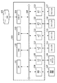
図1は、本実施例に係る画像処理装置100のシステム構成の一例を示す図である。同図において、CPU101は、RAM102をワークメモリとして、ROM103及びハードディスクドライブ(HDD)105に格納されたプログラムを実行し、システムバス118を介して後述する各構成を制御する。これにより、後述する様々な処理が実行される。
FIG. 1 is a diagram illustrating an example of a system configuration of an
HDDインタフェイス(I/F)104は、HDD105や光ディスクドライブなどの二次記憶装置を接続する、例えばシリアルATA(SATA)等のインタフェイスである。
The HDD interface (I / F) 104 is an interface such as serial ATA (SATA) for connecting a secondary storage device such as the
CPU101は、HDDI/F104を介して、HDD105からのデータの読み出し、およびHDD105へのデータの書き込みが可能である。さらにCPU101は、HDD105に格納されたデータをRAM102に展開し、同様に、RAM102に展開されたデータをHDD105に保存することが可能である。そしてCPU101は、RAM102に展開したデータをプログラムとみなし、実行することができる。
The
撮像インタフェイス(I/F)106は、複数の撮像部(カメラユニット)を備えた撮像装置107を接続する、例えばUSBやIEEE1394などのシリアルバスインタフェイスである。CPU101は、撮像I/F106を介して撮像装置107を制御し、撮像を行うことが可能である。さらに、CPU101は、撮像I/F106を介して撮像装置107から撮像したデータを読み込むことが可能である。
An imaging interface (I / F) 106 is a serial bus interface such as USB or IEEE 1394 for connecting an
入力インタフェイス(I/F)108は、キーボードやマウスなどの入力デバイス109を接続する、例えばUSBやIEEE1394等のシリアルバスインタフェイスである。CPU101は、入力I/F108を介して入力デバイス109からデータを読み込むことが可能である。
An input interface (I / F) 108 is a serial bus interface such as USB or IEEE 1394 for connecting an
出力インタフェイス(I/F)110〜113は、画像をスクリーンなどに投影することにより表示する画像投影装置(プロジェクタ)114〜117を接続する、例えばDVIやHDMI等の映像出力インタフェイスである。CPU101は、出力I/F110〜113を介してプロジェクタ114〜117にデータを送り、表示を実行させることができる。
The output interfaces (I / F) 110 to 113 are video output interfaces such as DVI and HDMI that connect image projection apparatuses (projectors) 114 to 117 that display images by projecting them onto a screen or the like. The
図2は、実施例1に係る、複数の撮像部を備えた多眼方式による撮像装置107の一例を示した図である。撮像装置107には、画像を撮像する9個の撮像部201〜209を備えている。9個の撮像部は、正方格子上に均等に配置されている。
FIG. 2 is a diagram illustrating an example of a
撮像の指示を受けると、撮像部201〜209が被写体の光情報をセンサ(撮像素子)で受光し、受光した信号がA/D変換されて、複数の画像(デジタルデータ)が同時に取得される。
When receiving an imaging instruction, the
このような多眼方式の撮像装置により、同一の被写体を複数の視点位置から撮像した画像データ(多視点画像データ)を得ることができる。 With such a multi-eye imaging device, image data (multi-view image data) obtained by imaging the same subject from a plurality of viewpoint positions can be obtained.
なお、ここでは撮像部の数を9個としたが撮像部の数は9個に限定されない。また、ここでは9個の撮像部が正方格子上に均等に配置される例について説明したが、各撮像部の配置は任意である。例えば、放射状や直線状に配置してもよいし、まったくランダムに配置してもよい。 Although the number of imaging units is nine here, the number of imaging units is not limited to nine. In addition, although an example in which nine image capturing units are uniformly arranged on a square lattice has been described here, the arrangement of each image capturing unit is arbitrary. For example, they may be arranged radially or linearly, or may be arranged at random.
さらに、上述のような複数の撮像部を備えた撮像装置を用いる代わりに、一つの撮像部を有する撮像装置を用いて撮像位置を変えながら複数回撮像することで、多視点画像データを得るようにしてもよい。 Furthermore, instead of using an imaging device having a plurality of imaging units as described above, multi-viewpoint image data is obtained by imaging multiple times while changing the imaging position using an imaging device having one imaging unit. It may be.
本実施例では、図2に示す撮像装置107で同時に撮像した画像データを基に、4個のプロジェクタ114〜117の投影領域をつなぎ合わせて後述の表示領域を構成し、単一の画像を表示する場合について説明する。図3は、撮像装置107で同時に撮像した画像データを基に、複数のプロジェクタの投影領域をつなぎ合わせた単一の画像を表示する様子を示す図である。異なる3種類の破線でそれぞれ示された3つの矩形領域301〜303は、撮像装置107における複数の撮像部のうちの3つの撮像部についての撮像範囲をそれぞれ示している。すなわち、撮像範囲301は撮像部204に、撮像範囲302は撮像部205に、撮像範囲303は撮像部206にそれぞれ対応している。スクリーン304にはプロジェクタ114〜117による4つの投影領域305〜308が部分的に重複するように投影されている。そして、斜線で示された領域309は表示領域であり、ここに4つの投影領域305〜308がつなぎ合わされて表示される。
In this embodiment, based on the image data simultaneously captured by the
この際、一の撮像部(個眼)で撮像した画像上において、投影領域に対応する画素数が各プロジェクタ114〜117の画面解像度よりも小さい場合は、複数の撮像部で撮像した画像を基に投影領域をつなぎ合わせるための処理を行う。なお、撮像部201〜209は全て同じ画角及びセンサ画素数であり、かつスクリーン304に正対しているものとする。
At this time, if the number of pixels corresponding to the projection area is smaller than the screen resolution of each
また、プロジェクタの数は4つに限定されるものではなく、例えば6つや9つ等、任意の数で構わないことは言うまでもない。 Needless to say, the number of projectors is not limited to four, and may be any number such as six or nine.
図4は、本実施例に係る画像処理装置100の機能構成図である。この図4に示される構成は、画像処理アプリケーションソフトウェアとして実現される。すなわち、CPU101がHDD105等に格納された各種ソフトウェア(コンピュータプログラム)を実行することで実現される。
FIG. 4 is a functional configuration diagram of the
画像処理装置100は、校正用パターン画像の画像データ、撮像パラメータ、プロジェクタ情報および表示用画像の画像データを入力デバイス109あるいはHDD105等の記憶装置から取得する。撮像パラメータには、各撮像部201〜209の露光時間やISO感度等の撮像条件を含む。そして、プロジェクタ情報には、プロジェクタ114〜117の画面解像度の情報を含む。
The
撮像装置制御部401は、取得された撮像パラメータに含まれる撮像条件に基づき、撮像装置107に対して撮像命令を送る。撮像装置107は受け取った撮像命令に基づき撮像を行うと、撮像された画像データが撮像I/F106を介して補正係数算出用画像生成部402に送られる。
The imaging
補正係数算出用画像生成部402は、取得されたプロジェクタ情報に含まれるプロジェクタの画面解像度と撮像装置107から受け取った撮像画像データに基づき、補正係数算出用画像データを生成する。生成された補正係数算出用画像データは補正係数算出部403に送られる。
The correction coefficient calculation
補正係数算出部403は、受け取った補正係数算出用画像データに基づいて、表示用画像に対して幾何補正を施すために必要な補正係数を算出する。算出された補正係数は画像補正部404に送られる。
The correction
画像補正部404は、取得された表示用画像データに幾何補正処理を施し、補正画像データを生成する。生成された補正画像データは画像出力部405に送られる。
The
画像出力部405は、校正用パターン画像データおよび補正画像データを出力I/F110〜113を介してプロジェクタ114〜117に出力する。
The
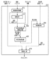
図5は、本実施例に係る画像処理装置100における画像処理の流れを示すフローチャートである。実際には、以下に示す手順を記述したコンピュータ実行可能なプログラムをROM103あるいはHDD105からRAM102上に読み込んだ後に、CPU101によって該プログラムを実行することによって当該処理が実行される。
FIG. 5 is a flowchart illustrating the flow of image processing in the
ステップ501において、画像処理装置100は、校正用パターン画像としての幾何補正用画像の画像データ、撮像パラメータ、プロジェクタ情報、表示用画像の画像データを取得する。図6は、幾何補正用画像の一例を示す図であり、(a)は無地の白画像、(b)は格子模様の格子画像である。以下では、(a)の白画像を幾何補正用画像に採用した場合を例に説明するものとする。
In step 501, the
ステップ502において、画像出力部405は、取得した校正用パターン画像の画像データをプロジェクタ114〜117に出力する。これを受けて各プロジェクタ114〜117は、スクリーン304に校正用パターン画像(白画像)を投影する。
In
ステップ503において、撮像装置制御部401は、撮像命令を撮像装置107に与え、撮像装置107から撮像画像(スクリーンに投影された白画像を撮像した画像)のデータを取得する。この際、プロジェクタ114〜117の全投影状態と、プロジェクタ毎の個別の投影状態の2種類の撮像画像データを取得する。図7は、本ステップで取得される撮像画像データの一例を示す図である。画像セット0は、白画像が全てのプロジェクタによってスクリーン304に投影された状態を撮像した画像の組である。画像セット1〜画像セット4は、白画像が個別のプロジェクタによってスクリーン304に投影された状態を撮像した画像の組である。画像セット1はプロジェクタ114に、画像セット2はプロジェクタ115に、画像セット3はプロジェクタ116に、画像セット4はプロジェクタ117にそれぞれ対応する。そして、いずれの画像セットも、撮像部201〜209に対応した計9枚の画像を含んでいる。
In
ステップ504において、補正係数算出用画像生成部402は、ステップ501で取得したプロジェクタ情報及びステップ503で取得した撮像画像データを基に、補正係数算出用画像データを生成する。具体的には、まず、プロジェクタ情報に含まれる各プロジェクタの画面解像度と、撮像画像の各プロジェクタの投影領域における画素数とを比較する。比較の結果、プロジェクタの画面解像度の方が小さい場合は、撮像画像に含まれる画像のうち撮像部205で撮像した画像を補正係数算出用画像とする。逆に、プロジェクタの画面解像度の方が大きい場合は、撮像部201〜209で撮像した複数の画像を用いて高解像度処理を行って補正係数算出用画像を生成する。この補正係数算出用画像生成処理の詳細については後述する。
In step 504, the correction coefficient calculation
ステップ505において、補正係数算出部403は、生成された補正係数算出用画像データを基に、表示用画像への幾何補正処理の際に使用する補正係数を算出する。補正係数算出処理の詳細については後述する。
In
ステップ506において、画像補正部404は、生成された補正係数を用いて表示用画像に対し幾何補正処理を施し、プロジェクタ114〜117で投影するための補正画像データを生成する。この補正処理の詳細については後述する。
In
ステップ507において、画像出力部405は、生成された補正画像データをプロジェクタ114〜117に出力する。これを受けて各プロジェクタ114〜117は、スクリーン304に補正画像を投影する。
In
以上の処理により、表示用画像データが、複数のプロジェクタ114〜117によって単一の画像として投影される。
Through the above processing, the display image data is projected as a single image by the plurality of
<補正係数算出用画像生成処理>
図8は、補正係数算出用画像生成処理の流れを示すフローチャートである。
<Image generation processing for correction coefficient calculation>
FIG. 8 is a flowchart showing the flow of correction coefficient calculation image generation processing.
ステップ801において、補正係数算出用画像生成部402は、撮像画像のデータを受け取る。
In
ステップ802において、補正係数算出用画像生成部402は、プロジェクタ情報より、各プロジェクタ114〜117の画面解像度を取得する。画面解像度の情報は、例えば、1920×1080など、幅:Wの画素の数と高さ:Hの画素の数で与えられる。
In step 802, the correction coefficient calculation
ステップ803において、補正係数算出用画像生成部402は、受け取った撮像画像データからプロジェクタ114〜117の投影領域をそれぞれ検出し、各投影領域の画素数を算出する。この画素数算出処理では、撮像画像データ内の画像セット1〜4に各々含まれる所定の撮像部(ここでは、撮像部205とする。)で撮像された4枚の画像を使用する。なお、これら4枚の画像を、プロジェクタ114〜117の順にそれぞれ投影領域検出用画像1〜投影領域検出用画像4と便宜的に呼ぶこととする。図9は、各投影領域の画素数を算出する過程を示す図である。最初に、投影領域検出用画像1〜4に対して閾値処理による二値化を行う。これにより、投影領域検出用画像1〜4の画素値が輝度値に変換される。そして、予め設定しておいた閾値thと、投影領域検出用画像1〜4の各画素における輝度値とを比較し、輝度値が閾値th以上の画素を投影領域、輝度値が閾値thより小さい画素をその他の領域とし、それぞれ異なるラベル値を与えた二値画像1〜4を生成する。そして、二値画像1〜4に含まれる投影領域の画素数をそれぞれカウントする。T1〜T4は、カウントされた画素数を表す。
In
ステップ804において、補正係数算出用画像生成部402は、ステップ802で取得したプロジェクタ114〜117の画面解像度から求められる画素数とステップ803で取得した各投影領域の画素数とを比較する。具体的には、まず、画面解像度のWとHとの積を求め、求められた値をSとする(W×H=S)。そして、得られた値SとT1〜T4とを比較する。その結果、画面解像度から求められる画素数Sが、各投影領域の画素数T1〜T4のいずれか1つよりも大きい場合はステップ805へ進む。一方、画面解像度から求められる画素数Sが、どのT1〜T4よりも小さい場合は、撮像画像データ内の各画像セットに含まれる所定の撮像部で撮像した画像(例えば、撮像部205で撮像した画像)を補正係数算出用画像に決定しステップ806に進む。
In step 804, the correction coefficient calculating
ステップ805において、補正係数算出用画像生成部402は、撮像画像を基に高解像度化処理(本実施例では超解像処理)を行い、補正係数算出用画像を生成する。図10は、本実施例における高解像度化処理の様子を説明する図である。図10に示すように、画像セット0〜4に対しそれぞれ超解像処理を施し、高解像度画像0〜4を生成する。超解像処理としては、MAP(Maximum A Posterior)法やIBP(Iterative Back Projection)法などの既存の方法が適用可能である。以下、MAP法を用いて画像セット0から高解像度画像0を生成する場合について述べる。MAP法は、二乗誤差に高解像度画像の確率情報を付加した評価関数を最小化するような高解像度画像を推定する方法である。具体的には、下記に示す式(1)に従い高解像度画像に対するある先見情報と画像間の位置ずれを表すパラメータを利用し、事後確率を最大化する最適問題として高解像度画像の推定を行う。
In

ここで、Xは高解像度画像0、Ykは画像セット0に含まれる画像データである。Dはあらかじめ設定しておいたダウンサンプリング処理を表す行列である。Bはあらかじめ設定しておいたPSFによる劣化処理を行う行列である。Mは画像データ間の位置ずれを表す行列であり、撮像部205で撮像した画像を基準に他の画像の位置ずれ量を推定することで求める。Cは推定された高解像度画像0に適用される線形フィルタを表す行列であり、例えばラプラシアンフィルタ等が適用できる。σは画像セット0に含まれる画像データのノイズ量の標準偏差、αは平滑化度合いを調整するパラメータである。式(1)に示す最小化問題を最急降下法を用いて解くことで、画像セット0に含まれる画像データから高解像度画像0を推定する。このような超解像処理を画像セット0〜4にそれぞれ施して生成された高解像度画像0〜4が、補正係数算出用画像となる。
Here, X is the high-resolution image 0, and Yk is the image data included in the image set 0. D is a matrix representing preset downsampling processing. B is a matrix for performing deterioration processing by PSF set in advance. M is a matrix representing the positional deviation between the image data, and is obtained by estimating the positional deviation amount of other images based on the image captured by the
ステップ806において、補正係数算出用画像生成部402は、生成された補正係数算出用画像データを補正係数算出部403に出力し、本処理を終了する。
In step 806, the correction coefficient calculation
なお、上記ステップ804においては、プロジェクタ114〜117の画面解像度から求められる画素数と投影領域の画素数との比較を行った。しかし、例えば、投影領域に外接する矩形を検出しその幅W’および高さH’を画面解像度のWおよびHと比較するなどの方法でも構わない。
In step 804, the number of pixels obtained from the screen resolution of the
また、プロジェクタ114〜117の画面解像度(画素数)と投影領域の画素数との関係が予め分かっていれば、その情報をHDD105等に記憶しておき、ステップ802〜ステップ804のステップを省くようにしてもよい。
If the relationship between the screen resolution (number of pixels) of the
<補正係数算出処理>
図11は、補正係数算出処理の流れを示すフローチャートである。
<Correction coefficient calculation process>
FIG. 11 is a flowchart showing the flow of correction coefficient calculation processing.
ステップ1101において、補正係数算出部403は、補正係数算出用画像のデータを受け取る。なお、以下の説明では、補正係数算出用画像データとして高解像度画像0〜4の画像データが含まれるものとして説明する。
In step 1101, the correction
ステップ1102において、補正係数算出部403は、表示用画像を投影する表示領域を決定する。具体的には、受け取った高解像度画像データのうち高解像度画像0をユーザが参照しながら、表示領域となる矩形領域をマウス等で指定する。そして、当該指定された領域が表示領域に設定される。この場合において、設定される表示領域のアスペクト比は表示用画像と同一にする。ここで、図12に示すように表示領域の四隅の画素をそれぞれP00〜P03とし、このP00〜P03に対応する表示用画像の四隅の画素をそれぞれQ00〜Q03とする。
In step 1102, the correction
ステップ1103において、補正係数算出部403は、表示用画像と高解像度画像0との間の補正係数(幾何変換係数)を、ステップ1102で設定された表示領域の四隅P00〜P03および表示用画像の四隅Q00〜Q03を用いて算出する。算出される幾何変換係数が、図12において、a00〜a07で示されている。以下、幾何変換係数の算出方法について述べる。
In
表示用画像内の画素を(x、y)、高解像度画像0内の画素を(x”、y”)としたとき、a00〜a07、x、y、x”、y”、の関係は式(2)で表すことができる。 The relationship between a 00 to a 07 , x, y, x ″, y ″ when the pixel in the display image is (x, y) and the pixel in the high resolution image 0 is (x ″, y ″). Can be represented by formula (2).
式(2)を展開し、高解像度画像0の四隅の画素P00〜P03の座標と、P00〜P03に対応する表示用画像の四隅の画素Q00〜Q03の座標を用いることで、式(3)の連立方程式を導くことができる。 Expression (2) is developed, and the coordinates of the four corner pixels P00 to P03 of the high-resolution image 0 and the coordinates of the four corner pixels Q00 to Q03 of the display image corresponding to P00 to P03 are used. The simultaneous equations can be derived.
ここで、P00〜P03の座標をそれぞれ(x0、y0)〜(x3、y3)、Q00〜Q03の座標をそれぞれ(x”0、y”0)〜(x”3、y”3)とする。この式(3)で示される連立方程式を解くことによって幾何変換係数a00〜a07が算出される。 Here, each of the coordinates of P00~P03 (x 0, y 0) ~ (x 3, y 3), respectively the coordinates of Q00~Q03 (x "0, y" 0) ~ (x "3, y" 3 ). The geometric transformation coefficients a 00 to a 07 are calculated by solving the simultaneous equations represented by the equation (3).
ステップ1104において、補正係数算出部403は、高解像度画像1〜4と補正画像との間の幾何変換係数を算出する。ここで、補正画像データは、プロジェクタ114〜117で各々投影される部分画像データ(部分画像m、m=1〜4 以下、同じ。)からなる。算出される幾何変換係数が、図13において、am0〜am7(a10〜a17、a20〜a27、a30〜a37、a40〜a47)で示されている。以下、算出方法について述べる。
In
まず、高解像度画像1〜4のそれぞれに対してコーナー検出処理を施し、部分画像1〜4の四隅の画素Pm0〜Pm3に対応する高解像度画像1〜4の四隅の画素Qm0〜Qm3を検出する(図13参照)。以下、これらの対応する画素の座標を用いてステップ1103と同様に4組の幾何変換係数am0〜am7を算出する。高解像度画像1〜4内の画素を(x”、y”)、部分画像1〜4内の画素を(x’、y’)、としたときam0〜a07、x”、y”、x’、y’の関係は式(4)で表すことができる。
First, corner detection processing is performed on each of the
式(4)を展開し、部分画像1〜4の四隅の画素Pm0〜Pm3の座標と、Pm0〜Pm3に対応する高解像度画像1〜4の画素Qm0〜Qm3の座標を用いることで、式(5)の連立方程式を導くことができる。
By developing the equation (4) and using the coordinates of the pixels Pm0 to Pm3 at the four corners of the
ここで、Pm0〜Pm3の座標をそれぞれ(x”0、y”0)〜(x”3、y”3)、Q00〜Q03の座標をそれぞれ(x’0、y’0)〜(x’3、y’3)とする。この式(5)で示される連立方程式を解くことによって幾何変換係数am0〜am7が算出される。 Here, each of the coordinates of the Pm0~Pm3 (x "0, y" 0) ~ (x "3, y" 3), Q 00 ~Q 03 of coordinates each (x '0, y' 0 ) ~ ( x ′ 3 , y ′ 3 ). The geometric transformation coefficients a m0 to a m7 are calculated by solving the simultaneous equations represented by the equation (5).
ステップ1105において、補正係数算出部403は、ステップ1103及びステップ1104で各々算出された幾何変換係数a00〜a07とam0〜m7(a10〜a17、a20〜a27、a30〜a37、a40〜a47)を補正係数として出力する。
In
なお、本実施例では、ステップ1102においてユーザの手動による指定に基づいて表示領域を設定することとしたが、表示領域の設定方法はこれに限るものではない。例えば、高解像度画像0からプロジェクタ114〜117による投影領域を検出し、検出された投影領域に内接するように表示領域を自動で設定してもよい。
In this embodiment, the display area is set based on the user's manual designation in step 1102, but the display area setting method is not limited to this. For example, the projection area by the
<画像補正処理>
図14は、画像補正処理の流れを示すフローチャートである。
<Image correction processing>
FIG. 14 is a flowchart showing the flow of image correction processing.
ステップ1401において、画像補正部404は、表示用画像のデータを受け取る。
In
ステップ1402において、画像補正部404は、補正係数算出部403から補正係数を取得する。
In step 1402, the
ステップ1403において、画像補正部404は、処理対象とする画像を選択する。処理開始直後の時点では、初期化処理により、処理対象画像として部分画像1が選択される。
In
ステップ1404において、画像補正部404は、選択された処理対象画像における処理対象画素{座標:(x’、y’)}を選択する。処理開始直後の時点では、初期化処理により、(0,0)が座標の初期値として選択される。
In
ステップ1405において、画像補正部404は、取得した補正係数(幾何変換係数)を用いて処理対象画素に対応する表示用画像上の画素{座標:(x、y)}を算出する。この際、図15に示すように、幾何変換係数a00〜07および幾何変換係数(a10〜a17、a20〜a27、a30〜a37、a40〜a47)のうち処理対象画像に対応したものを用いて算出処理を行う。例えば、処理対象画像として部分画像1が選択されている場合であれば、まず、幾何変換係数a10〜a17を用いて選択された処理対象画素に対応する処理対象画像上の座標(x”、y”)を式(4)に従って算出する。その後、幾何変換係数a00〜07を用いて、算出された座標(x”、y”)に対応する表示用画像上の座標(x、y)を式(2)に従って算出する。
In
ステップ1406において、画像補正部404は、算出した表示用画像上の座標(x、y)に対応する画素値を算出し、選択された処理対象画素{座標:(x’、y’)}の画素値とする。
In step 1406, the
ステップ1407において、画像補正部404は、処理対象画像内のすべての画素について画素値が算出されたかどうかを判定する。算出されていない画素がある場合はステップ1404へ戻り、次の画素が選択される。一方、すべての画素について画素値が算出されていれば、ステップ1408へ進む。
In
ステップ1408において、画像補正部404は、すべての部分画像1〜4について処理が終了したかどうかを判定する。未処理の部分画像があれば、ステップ1403へ戻り、次の部分画像を処理対象画像に選択する。一方、すべての部分画像について処理が終了していれば、ステップ1409へ進む。
In step 1408, the
ステップ1409において、画像補正部404は、幾何補正処理のされた部分画像1〜4の画像データを画像出力部405に出力する。
In
そして、幾何補正処理のされた部分画像1〜4がプロジェクタ114〜117によってスクリーン304に投影される。
Then, the
このように本実施例によれば、複数のプロジェクタによって投影される画像をつなぎ合わせて単一の画像を表示する際に、各画像に対し適切な補正がなされる。その結果、投影画像間の位置ずれを抑制し解像感を向上させることができる。 As described above, according to the present embodiment, when images projected by a plurality of projectors are connected to display a single image, appropriate correction is performed on each image. As a result, it is possible to suppress the positional deviation between the projected images and improve the resolution.
(実施例2)
実施例1では、画角の等しい撮像部を複数備えた撮像装置を用いて、スクリーンに投影された校正用パターン画像を撮像する態様について説明した。次に、画角の異なる撮像部を複数備えた撮像装置を使用する態様について、実施例2として説明する。なお、実施例1と共通する部分については説明を簡略化ないしは省略し、ここでは差異点を中心に説明することとする。
(Example 2)
In the first embodiment, the aspect in which the calibration pattern image projected on the screen is captured using the imaging apparatus including a plurality of imaging units having the same angle of view has been described. Next, an embodiment in which an imaging apparatus including a plurality of imaging units having different angles of view is used will be described as a second embodiment. Note that description of parts common to the first embodiment is simplified or omitted, and here, differences will be mainly described.
図16は、実施例2に係る、複数の撮像部を備えた多眼方式による撮像装置1610の一例を示した図である。本実施例に係る撮像装置1610は、二種類の撮像部で構成される。1つは中央に位置する撮像部1601であり、もう1つはその周囲を囲むように配置される撮像部1602〜1609である。撮像部1601と撮像部1602〜1609とでは焦点距離が異なり、後者の焦点距離の方が長い。そのため、図17に示すように撮像部1602〜1609による撮像範囲は、撮像部1601による撮像範囲と比較して小さくなる。
FIG. 16 is a diagram illustrating an example of a
図18は、本実施例に係る撮像装置1610によって、スクリーンに投影された校正用パターン画像を撮像した撮像画像データの一例を示す図である。実施例1と同様、画像セット0は全てのプロジェクタによって投影された状態を撮像した画像の組であり、画像セット1〜画像セット4は、それぞれ別個のプロジェクタによって投影された状態を撮像した画像の組である。そして、画像セット1〜4はプロジェクタ114〜117にそれぞれ対応しており、いずれの画像セットも、撮像部1601〜1609に対応した計9枚の画像が含まれている。
FIG. 18 is a diagram illustrating an example of captured image data obtained by capturing the calibration pattern image projected on the screen by the
上記のような撮像画像データが得られる本実施例では、実施例1と比較し、図8のフローチャートのステップ805で行う高解像度化処理の内容が異なってくる。以下、本実施例における高解像度化処理について説明する。
In the present embodiment in which the captured image data as described above is obtained, the content of the high resolution processing performed in
本実施例におけるステップS705では、撮像画像データ1801に含まれる画像セット0〜4にそれぞれスティッチ処理を施すことにより、図19に示されるような高解像度画像0〜4からなる画像データを生成する。スティッチ処理としては、例えば以下に述べる方法が適用可能である。まず、各画像セット中の撮像部1602〜1609で撮像された画像と、それらの画像に対応する撮像部1601で撮像された画像内の領域との差分を算出する。そして、算出された差分に応じた補正処理を撮像部1602〜1609で撮像された画像に対して実行する。最後に、補正後の各画像を合成し、高解像度画像を生成する。なお、スティッチ処理の他の方法として、撮像画像内から抽出した特徴点をマッチングさせることにより画像をつなぎ合わせる方法なども適用可能である。
In step S705 in the present embodiment, image data including high resolution images 0 to 4 as shown in FIG. 19 is generated by performing stitch processing on the image sets 0 to 4 included in the captured
上記のような処理を図19で示される画像セット0〜4にそれぞれ施すことにより、高解像度画像0〜4が生成され、それらが補正計数算出用画像として、補正計数算出部403に出力される。
By applying the above processing to each of the image sets 0 to 4 shown in FIG. 19, high-resolution images 0 to 4 are generated, and these are output to the correction
その余の処理は、実施例1と同じであるので、以降の説明は省略する。 Since the rest of the processing is the same as in the first embodiment, the following description is omitted.
Claims (9)
前記複数の投影手段から投影された複数の投影画像を、複数の撮像手段を有する撮像装置を用いて互いに異なる視点位置から撮像することによって得られた、複数の撮像画像を入力する入力手段と、
前記複数の撮像画像における、それぞれが前記複数の投影画像のうちの一つに対応する画像領域である複数の投影領域の中で、対応する投影画像よりも画素数が少ない投影領域が存在する場合に、前記複数の撮像画像を用いて、少なくとも前記対応する投影画像よりも画素数が少ない投影領域の解像度が向上した高解像度画像を生成する生成手段と、
前記複数の投影手段からの投影により表示される1枚の画像において、前記複数の投影手段から投影される各画像に対応する領域を示す領域情報を取得する取得手段と、
前記領域情報が示す各領域において、位置合わせの為の基準点を設定する設定手段と、
前記投影領域の中で、前記基準点に対応する点を検出する検出手段と、
前記高解像度画像に基づいて、前記複数の投影手段から投影される画像を変形させるための変形パラメータであって、前記複数の投影手段から投影される各画像が、前記領域情報が示す対応する領域にそれぞれ投影されるように、前記変形パラメータを決定する決定手段と
を有し、
前記決定手段は、前記検出手段により検出された点と、前記設定手段によって設定された前記基準点とが重なるように前記変形パラメータを決定する
ことを特徴とする画像処理装置。 In a projection system that displays a single image by simultaneously projecting a plurality of images from a plurality of projection means, an image processing apparatus connected to the plurality of projection means,
Input means for inputting a plurality of captured images obtained by capturing a plurality of projection images projected from the plurality of projection means from different viewpoint positions using an imaging device having a plurality of imaging means;
In the plurality of captured images, a plurality of projection areas, each of which corresponds to one of the plurality of projection images, includes a projection area having a smaller number of pixels than the corresponding projection image And generating means for generating a high-resolution image in which the resolution of a projection region having a smaller number of pixels than at least the corresponding projection image is improved using the plurality of captured images;
An acquisition unit configured to acquire area information indicating an area corresponding to each image projected from the plurality of projection units in one image displayed by projection from the plurality of projection units;
In each area indicated by the area information, setting means for setting a reference point for alignment;
Detecting means for detecting a point corresponding to the reference point in the projection area;
A deformation parameter for deforming an image projected from the plurality of projection units based on the high-resolution image, and each image projected from the plurality of projection units corresponds to a region indicated by the region information respectively, as projected, it has a determining means for determining the deformation parameter,
The image processing apparatus , wherein the determining unit determines the deformation parameter so that a point detected by the detecting unit overlaps the reference point set by the setting unit.
前記生成手段は、前記第一の撮像画像群を用いて第一の高解像度画像を生成し、前記第二の撮像画像群を用いて第二の高解像度画像を生成し、
前記決定手段は、前記第一の高解像度画像を用いて前記第一の投影手段に対応する第一の変形パラメータを決定し、前記第二の高解像度画像を用いて前記第二の投影手段に対応する第二の変形パラメータを決定する
ことを特徴とする請求項1に記載の画像処理装置。 The plurality of captured images include a first captured image group obtained by capturing the first projected image projected from the first projecting unit from a plurality of different viewpoint positions, and a second group different from the first projecting unit. A second captured image group obtained by capturing the second projected image projected from the projecting means from a plurality of different viewpoint positions;
The generating means generates a first high-resolution image using the first captured image group, generates a second high-resolution image using the second captured image group,
The determining unit determines a first deformation parameter corresponding to the first projecting unit using the first high-resolution image, and determines the second projecting unit using the second high-resolution image. The image processing apparatus according to claim 1, wherein a second deformation parameter corresponding to the second deformation parameter is determined.
前記検出手段は、前記投影領域についてコーナー検出処理を行うことにより、前記基準点に対応する点を検出する
ことを特徴とする請求項1に記載の画像処理装置。 The setting means sets the four corners of each region indicated by the region information as the reference point,
The image processing apparatus according to claim 1 , wherein the detection unit detects a point corresponding to the reference point by performing a corner detection process on the projection area.
前記広角画像における投影領域の画素数が対応する投影画像の画素数よりも大きい場合には、前記決定手段は前記広角画像を用いて前記変形パラメータを決定し、
前記広角画像における投影領域の画素数が対応する投影画像の画素数よりも小さい場合には、
前記生成手段は、前記複数の望遠画像をスティッチ合成することで前記高解像度画像を生成し、前記決定手段は、前記高解像度画像を用いて前記変形パラメータを決定する
ことを特徴とする請求項1乃至3のいずれか一項に記載の画像処理装置。 The plurality of captured images include a plurality of telephoto images in which the number of pixels of the projection region is larger than the number of pixels of the corresponding projection image, and at least one wide-angle image having a wider angle of view than the plurality of telephoto images. ,
When the number of pixels of the projection area in the wide-angle image is larger than the number of pixels of the corresponding projection image, the determining means determines the deformation parameter using the wide-angle image,
When the number of pixels of the projection area in the wide-angle image is smaller than the number of pixels of the corresponding projection image,
The generation unit generates the high-resolution image by stitch-combining the plurality of telephoto images, and the determination unit determines the deformation parameter using the high-resolution image. The image processing device according to any one of claims 1 to 3 .
前記複数の投影手段から投影された複数の投影画像を、複数の撮像手段を有する撮像装置を用いて互いに異なる視点位置から撮像することによって得られた、複数の撮像画像を入力する入力工程と、
前記複数の撮像画像における、それぞれが前記複数の投影画像のうちの一つに対応する画像領域である複数の投影領域の中で、対応する投影画像よりも画素数が少ない投影領域が存在する場合に、前記複数の撮像画像を用いて、少なくとも前記対応する投影画像よりも画素数が少ない投影領域の解像度が向上した高解像度画像を生成する生成工程と、
前記複数の投影手段からの投影により表示される1枚の画像において、前記複数の投影手段から投影される各画像に対応する領域を示す領域情報を取得する取得工程と、
前記領域情報が示す各領域において、位置合わせの為の基準点を設定する設定工程と、
前記投影領域の中で、前記基準点に対応する点を検出する検出工程と、
前記高解像度画像に基づいて、前記複数の投影手段から投影される画像を変形させるための変形パラメータであって、前記複数の投影手段から投影される各画像が、前記領域情報が示す対応する領域にそれぞれ投影されるように、前記変形パラメータを決定する決定工程と
を含み、
前記決定工程では、前記検出工程で検出された点と、前記設定工程で設定された前記基準点とが重なるように前記変形パラメータを決定する
むことを特徴とする画像処理方法。 In a projection system that displays a single image by simultaneously projecting a plurality of images from a plurality of projection means, the image processing method is executed by an image processing apparatus connected to the plurality of projection means,
An input step of inputting a plurality of captured images obtained by capturing a plurality of projected images projected from the plurality of projecting units from different viewpoint positions using an imaging device having a plurality of imaging units;
In the plurality of captured images, a plurality of projection areas, each of which corresponds to one of the plurality of projection images, includes a projection area having a smaller number of pixels than the corresponding projection image In addition, using the plurality of captured images, a generation step of generating a high-resolution image in which the resolution of a projection region having at least a smaller number of pixels than the corresponding projection image is improved,
An acquisition step of acquiring region information indicating a region corresponding to each image projected from the plurality of projection units in one image displayed by projection from the plurality of projection units;
In each region indicated by the region information, a setting step for setting a reference point for alignment;
A detection step of detecting a point corresponding to the reference point in the projection region;
A deformation parameter for deforming an image projected from the plurality of projection units based on the high-resolution image, and each image projected from the plurality of projection units corresponds to a region indicated by the region information as each of which is projected, the viewing including a determination step of determining the deformation parameter,
The image processing method according to claim 1, wherein in the determining step, the deformation parameter is determined so that the point detected in the detecting step and the reference point set in the setting step overlap .
Priority Applications (1)
| Application Number | Priority Date | Filing Date | Title |
|---|---|---|---|
| JP2012014145A JP5955003B2 (en) | 2012-01-26 | 2012-01-26 | Image processing apparatus, image processing method, and program |
Applications Claiming Priority (1)
| Application Number | Priority Date | Filing Date | Title |
|---|---|---|---|
| JP2012014145A JP5955003B2 (en) | 2012-01-26 | 2012-01-26 | Image processing apparatus, image processing method, and program |
Publications (3)
| Publication Number | Publication Date |
|---|---|
| JP2013153392A JP2013153392A (en) | 2013-08-08 |
| JP2013153392A5 JP2013153392A5 (en) | 2015-03-05 |
| JP5955003B2 true JP5955003B2 (en) | 2016-07-20 |
Family
ID=49049395
Family Applications (1)
| Application Number | Title | Priority Date | Filing Date |
|---|---|---|---|
| JP2012014145A Expired - Fee Related JP5955003B2 (en) | 2012-01-26 | 2012-01-26 | Image processing apparatus, image processing method, and program |
Country Status (1)
| Country | Link |
|---|---|
| JP (1) | JP5955003B2 (en) |
Families Citing this family (3)
| Publication number | Priority date | Publication date | Assignee | Title |
|---|---|---|---|---|
| JP7116543B2 (en) * | 2017-12-15 | 2022-08-10 | キヤノン株式会社 | PROJECTION CONTROL DEVICE, CONTROL METHOD THEREOF, AND PROJECTION SYSTEM |
| WO2019203002A1 (en) * | 2018-04-17 | 2019-10-24 | ソニー株式会社 | Information processing device and method |
| WO2020202786A1 (en) | 2019-03-29 | 2020-10-08 | 富士フイルム株式会社 | Image processing device, projection system, image processing method, and image processing program |
Family Cites Families (4)
| Publication number | Priority date | Publication date | Assignee | Title |
|---|---|---|---|---|
| JP3735158B2 (en) * | 1996-06-06 | 2006-01-18 | オリンパス株式会社 | Image projection system and image processing apparatus |
| JP2004015205A (en) * | 2002-06-04 | 2004-01-15 | Olympus Corp | Multi-projection system and correction data acquisition method in multi-projection system |
| JP2005244835A (en) * | 2004-02-27 | 2005-09-08 | Olympus Corp | Multiprojection system |
| JP2006140831A (en) * | 2004-11-12 | 2006-06-01 | Hitachi Ltd | Projector device |
-
2012
- 2012-01-26 JP JP2012014145A patent/JP5955003B2/en not_active Expired - Fee Related
Also Published As
| Publication number | Publication date |
|---|---|
| JP2013153392A (en) | 2013-08-08 |
Similar Documents
| Publication | Publication Date | Title |
|---|---|---|
| JP6330987B2 (en) | Image processing apparatus, image processing method, and storage medium | |
| US9665939B2 (en) | Image processing apparatus, control method, and recording medium | |
| JP5580164B2 (en) | Optical information processing apparatus, optical information processing method, optical information processing system, and optical information processing program | |
| US9344695B2 (en) | Automatic projection image correction system, automatic projection image correction method, and non-transitory storage medium | |
| JP5961945B2 (en) | Image processing apparatus, projector and projector system having the image processing apparatus, image processing method, program thereof, and recording medium recording the program | |
| US10134118B2 (en) | Information processing apparatus and method of obtaining information about a projection surface on which a target is projected | |
| JP2011180251A (en) | Correction information calculating device, image processing apparatus, image display system, and image correcting method | |
| JP2015060012A (en) | Image processing system, image processing device, image processing method and image processing program as well as display system | |
| JP2010028411A (en) | Image correcting apparatus, image correcting method, projector and projection system | |
| JP6045523B2 (en) | Image processing apparatus and control method thereof | |
| WO2018102990A1 (en) | System and method for rectifying a wide-angle image | |
| US20170142384A1 (en) | Image processing apparatus, image processing method, image projection system, and storage medium | |
| JP5955003B2 (en) | Image processing apparatus, image processing method, and program | |
| JP2011155412A (en) | Projection system and distortion correction method in the same | |
| US11416978B2 (en) | Image processing apparatus, control method and non-transitory computer-readable recording medium therefor | |
| US11830177B2 (en) | Image processing apparatus, control method and non-transitory computer-readable recording medium therefor | |
| JP5446285B2 (en) | Image processing apparatus and image processing method | |
| JP2016072691A (en) | Image processing system, control method of the same, and program | |
| JP5340021B2 (en) | Image processing apparatus, image processing method, and program | |
| JP5727969B2 (en) | Position estimation apparatus, method, and program | |
| JP6320165B2 (en) | Image processing apparatus, control method therefor, and program | |
| CN110402454B (en) | Image correction device, image correction method, and recording medium | |
| JP6299269B2 (en) | Image processing system, program, and projection apparatus | |
| JP2015080190A (en) | Extraction method, program, extraction device, and image projection device | |
| WO2021075314A1 (en) | Image processing device, image processing method, and computer-readable recording medium |
Legal Events
| Date | Code | Title | Description |
|---|---|---|---|
| A521 | Request for written amendment filed |
Free format text: JAPANESE INTERMEDIATE CODE: A523 Effective date: 20150120 |
|
| A621 | Written request for application examination |
Free format text: JAPANESE INTERMEDIATE CODE: A621 Effective date: 20150120 |
|
| A977 | Report on retrieval |
Free format text: JAPANESE INTERMEDIATE CODE: A971007 Effective date: 20150828 |
|
| A131 | Notification of reasons for refusal |
Free format text: JAPANESE INTERMEDIATE CODE: A131 Effective date: 20150929 |
|
| A521 | Request for written amendment filed |
Free format text: JAPANESE INTERMEDIATE CODE: A523 Effective date: 20151130 |
|
| TRDD | Decision of grant or rejection written | ||
| A01 | Written decision to grant a patent or to grant a registration (utility model) |
Free format text: JAPANESE INTERMEDIATE CODE: A01 Effective date: 20160517 |
|
| A61 | First payment of annual fees (during grant procedure) |
Free format text: JAPANESE INTERMEDIATE CODE: A61 Effective date: 20160614 |
|
| R151 | Written notification of patent or utility model registration |
Ref document number: 5955003 Country of ref document: JP Free format text: JAPANESE INTERMEDIATE CODE: R151 |
|
| LAPS | Cancellation because of no payment of annual fees |