JP5961945B2 - Image processing apparatus, projector and projector system having the image processing apparatus, image processing method, program thereof, and recording medium recording the program - Google Patents
Image processing apparatus, projector and projector system having the image processing apparatus, image processing method, program thereof, and recording medium recording the program Download PDFInfo
- Publication number
- JP5961945B2 JP5961945B2 JP2011178809A JP2011178809A JP5961945B2 JP 5961945 B2 JP5961945 B2 JP 5961945B2 JP 2011178809 A JP2011178809 A JP 2011178809A JP 2011178809 A JP2011178809 A JP 2011178809A JP 5961945 B2 JP5961945 B2 JP 5961945B2
- Authority
- JP
- Japan
- Prior art keywords
- image
- plane
- projector
- distance
- data
- Prior art date
- Legal status (The legal status is an assumption and is not a legal conclusion. Google has not performed a legal analysis and makes no representation as to the accuracy of the status listed.)
- Active
Links
Images

Classifications
-
- G—PHYSICS
- G01—MEASURING; TESTING
- G01B—MEASURING LENGTH, THICKNESS OR SIMILAR LINEAR DIMENSIONS; MEASURING ANGLES; MEASURING AREAS; MEASURING IRREGULARITIES OF SURFACES OR CONTOURS
- G01B11/00—Measuring arrangements characterised by the use of optical techniques
- G01B11/14—Measuring arrangements characterised by the use of optical techniques for measuring distance or clearance between spaced objects or spaced apertures
-
- G—PHYSICS
- G08—SIGNALLING
- G08G—TRAFFIC CONTROL SYSTEMS
- G08G1/00—Traffic control systems for road vehicles
- G08G1/16—Anti-collision systems
- G08G1/168—Driving aids for parking, e.g. acoustic or visual feedback on parking space
-
- H—ELECTRICITY
- H04—ELECTRIC COMMUNICATION TECHNIQUE
- H04N—PICTORIAL COMMUNICATION, e.g. TELEVISION
- H04N9/00—Details of colour television systems
- H04N9/12—Picture reproducers
- H04N9/31—Projection devices for colour picture display, e.g. using electronic spatial light modulators [ESLM]
- H04N9/3179—Video signal processing therefor
- H04N9/3185—Geometric adjustment, e.g. keystone or convergence
-
- H—ELECTRICITY
- H04—ELECTRIC COMMUNICATION TECHNIQUE
- H04N—PICTORIAL COMMUNICATION, e.g. TELEVISION
- H04N9/00—Details of colour television systems
- H04N9/12—Picture reproducers
- H04N9/31—Projection devices for colour picture display, e.g. using electronic spatial light modulators [ESLM]
- H04N9/3191—Testing thereof
- H04N9/3194—Testing thereof including sensor feedback
-
- G—PHYSICS
- G03—PHOTOGRAPHY; CINEMATOGRAPHY; ANALOGOUS TECHNIQUES USING WAVES OTHER THAN OPTICAL WAVES; ELECTROGRAPHY; HOLOGRAPHY
- G03B—APPARATUS OR ARRANGEMENTS FOR TAKING PHOTOGRAPHS OR FOR PROJECTING OR VIEWING THEM; APPARATUS OR ARRANGEMENTS EMPLOYING ANALOGOUS TECHNIQUES USING WAVES OTHER THAN OPTICAL WAVES; ACCESSORIES THEREFOR
- G03B17/00—Details of cameras or camera bodies; Accessories therefor
- G03B17/48—Details of cameras or camera bodies; Accessories therefor adapted for combination with other photographic or optical apparatus
- G03B17/54—Details of cameras or camera bodies; Accessories therefor adapted for combination with other photographic or optical apparatus with projector
-
- G—PHYSICS
- G03—PHOTOGRAPHY; CINEMATOGRAPHY; ANALOGOUS TECHNIQUES USING WAVES OTHER THAN OPTICAL WAVES; ELECTROGRAPHY; HOLOGRAPHY
- G03B—APPARATUS OR ARRANGEMENTS FOR TAKING PHOTOGRAPHS OR FOR PROJECTING OR VIEWING THEM; APPARATUS OR ARRANGEMENTS EMPLOYING ANALOGOUS TECHNIQUES USING WAVES OTHER THAN OPTICAL WAVES; ACCESSORIES THEREFOR
- G03B21/00—Projectors or projection-type viewers; Accessories therefor
- G03B21/14—Details
- G03B21/53—Means for automatic focusing, e.g. to compensate thermal effects
Landscapes
- Physics & Mathematics (AREA)
- Engineering & Computer Science (AREA)
- Multimedia (AREA)
- Signal Processing (AREA)
- General Physics & Mathematics (AREA)
- Geometry (AREA)
- Projection Apparatus (AREA)
- Transforming Electric Information Into Light Information (AREA)
- Controls And Circuits For Display Device (AREA)
- Control Of Indicators Other Than Cathode Ray Tubes (AREA)
- Image Processing (AREA)
- User Interface Of Digital Computer (AREA)
Description
本発明は、画像処理装置、その画像処理装置を有するプロジェクタ及びプロジェクタシステム、並びに、画像処理方法、そのプログラム及びそのプログラムを記録した記録媒体に関する。 The present invention relates to an image processing apparatus, a projector and a projector system having the image processing apparatus, an image processing method, a program thereof, and a recording medium on which the program is recorded.
プロジェクタは、画像をスクリーン等の対象物に投影する装置である。画像を投影する際、プロジェクタと対象物との傾斜角によって、投影される画像に台形歪みが生ずる場合がある。プロジェクタには、投影する画像の台形歪みを解消するために、画像処理装置により、投影する画像を予め補正(変形)するものがある。 A projector is a device that projects an image onto an object such as a screen. When projecting an image, trapezoidal distortion may occur in the projected image depending on the tilt angle between the projector and the object. Some projectors correct (deform) a projected image in advance by an image processing apparatus in order to eliminate trapezoidal distortion of the projected image.
ここで、画像処理装置には、プロジェクタと対象物との離間距離及び傾斜角に基づいて、投影する画像を補正するものがある。 Here, some image processing apparatuses correct an image to be projected based on a separation distance and an inclination angle between a projector and an object.
特許文献1は、所定のパターンである複数の対象点を投射対象物上に面状に投射し、その対象点までの距離に基づいて、投射対象物と背景との境界線(投射対象物の外形)を検出し、その境界線に対応するように、投射画像(投影する画像)を補正する技術を開示している。
プロジェクタで画像を投影するとき、多くの場合、所定の間、連続して画像を投影する。プロジェクタは、画像の投影中において、対象物またはプロジェクタが移動した場合に、投影する画像を補正するため、再度、離間距離及び傾斜角を測定する。 When projecting an image with a projector, in many cases, the image is projected continuously for a predetermined period. When the object or the projector moves during the image projection, the projector again measures the separation distance and the inclination angle in order to correct the image to be projected.
特許文献1に開示されている技術は、対象物までの距離に基づいて、投射画像を台形補正することができる。しかし、距離を測定するためにプロジェクタによる画像の投影を一時中断し、再度、所定のパターン等を投影する場合があった。
The technique disclosed in
本発明は、画像を投影中に、対象物とプロジェクタとの位置に関する関係が変化した場合において、画像を投影する動作を中断することなく、投影する画像を補正することができる画像処理装置を提供することを課題とする。 The present invention provides an image processing apparatus capable of correcting an image to be projected without interrupting the operation of projecting the image when the relationship between the position of the object and the projector changes during the image projection. The task is to do.
上記課題を解決するために、請求項1に係る本発明は、画像が投影されている対象物を含む領域を撮像して、画像データを取得する撮像手段と、前記画像データに基づき、前記対象物と前記撮像手段との離間距離に関する距離データを算出する測距手段と、前記距離データから、前記対象物に対応する平面を推定する平面推定手段と、前記距離データと前記平面に関する情報とに基づき、投影する画像の補正に関する情報を算出する補正情報算出手段と、を有することを特徴とする画像処理装置を提供する。
In order to solve the above-described problem, the present invention according to
本発明によれば、画像処理装置において、画像が投影されている対象物に対応する平面を推定することにより、投影する画像の補正に関する情報を算出することができる。 According to the present invention, in the image processing apparatus, it is possible to calculate information relating to correction of an image to be projected by estimating a plane corresponding to the object on which the image is projected.
対象物を含む領域を撮像した画像を画像処理することにより、投影する画像の補正に関する情報を算出する画像処理装置を用いて、本発明を詳細に説明する。 The present invention will be described in detail using an image processing apparatus that calculates information related to correction of an image to be projected by performing image processing on an image obtained by imaging a region including an object.
(画像処理装置の構成)
図1は、画像処理装置の一例を示す概略構成図である。
(Configuration of image processing apparatus)
FIG. 1 is a schematic configuration diagram illustrating an example of an image processing apparatus.
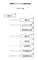
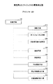
図1において、画像処理装置100は、制御手段110、撮像手段120、測距手段130、平面推定手段140、及び、補正情報算出手段150を含む。
In FIG. 1, the image processing apparatus 100 includes a
画像処理装置100は、撮像手段120により画像が投影される対象物(以下、投影対象物という。)を含む領域を撮像して画像データを取得し、測距手段130により撮像手段120から投影対象物までの距離に関する距離データを算出する。また、画像処理装置100は、平面推定手段140により投影対象物に対応する平面を推定し、推定した平面に関する情報と算出した距離データとに基づいて、投影する画像の補正(拡大縮小及び台形補正等の画像処理、以下、補正という。)に関する情報を算出する。
The image processing apparatus 100 captures an area including an object on which an image is projected by the imaging unit 120 (hereinafter referred to as a projection object), acquires image data, and the
ここで、投影対象物は、スクリーン、壁、及び、ホワイトボートなど、その外形表面に画像を投影することができるものを用いることができる。 Here, what can project an image on the external surface, such as a screen, a wall, and a white boat, can be used as the projection object.
制御手段110は、画像処理装置100全体の制御を行う手段である。制御手段110は、外部から入力された情報等に基づき、撮像手段120等を制御する。また、制御手段110は、外部から入力された情報等に基づき、画像処理装置100の画像処理の結果に関する情報を出力する制御を行う。
The
撮像手段120は、投影対象物を含む領域の像を撮像素子(イメージセンサ)に結像し、その撮像素子の画素出力信号(電気信号)から画像に関する画像データを取得する手段である。撮像手段120は、本実施形態では、ステレオカメラ、及び、撮像画像生成手段を含む。
The
ステレオカメラは、2つの撮像レンズ及び2つの撮像素子を備え、投影対象物を2つの撮像レンズ等で同時に撮影する。ここで、撮像レンズは、投影対象物の像を撮像素子に入射するものである。撮像素子は、複数の受光素子が格子状に配列された受光面を有し、撮像レンズを透過して入射した像をその受光面上に結像するものである。 The stereo camera includes two image pickup lenses and two image pickup devices, and simultaneously images a projection target using two image pickup lenses. Here, the imaging lens is for entering an image of the projection object into the imaging device. The imaging element has a light receiving surface in which a plurality of light receiving elements are arranged in a lattice pattern, and forms an image that has passed through the imaging lens and is incident on the light receiving surface.
撮像画像生成手段は、撮像素子の画素出力信号に基づき、投影対象物を含む領域の画像に関する画像データを生成する。 The captured image generation means generates image data relating to an image of an area including the projection target based on the pixel output signal of the image sensor.
測距手段130は、画像処理装置100(撮像手段120)から投影対象物までの距離を測定する手段である。測距手段130は、本実施形態では、撮像手段120が取得した2つ画像データに基づいて、三角測量の原理により、画像処理装置100(撮像手段120)から投影対象物までの距離を算出する。詳細は後述の(測距する動作)で説明する。
The distance measuring means 130 is a means for measuring the distance from the image processing apparatus 100 (imaging means 120) to the projection target. In the present embodiment, the
平面推定手段140は、測距手段130が算出した距離データに基づいて、投影対象物に対応する平面を再帰的に近似する。ここで、平面を再帰的に近似するとは、複数の位置に基づいて平面を近似的に推定した後、その推定した平面から所定の距離を離れた位置を除外して、平面を推定し直す方法(回帰分析法)である。詳細は後述の(平面を推定する動作)で説明する。 The plane estimation means 140 recursively approximates the plane corresponding to the projection object based on the distance data calculated by the distance measurement means 130. Here, recursively approximating a plane is a method of approximating a plane based on a plurality of positions and then re-estimating the plane by excluding a position away from the estimated plane by a predetermined distance. (Regression analysis method). Details will be described later (operation for estimating a plane).
補正情報算出手段150は、平面推定手段140が推定した平面に関する情報等に基づいて、投影する画像の補正に関する情報を算出する。詳細は後述の(補正情報を算出する動作)で説明する。
The correction
なお、以後の説明では、画像に関するデータとして、「コンテンツ画像データAimg」とは、PCなどから投影手段(プロジェクタなど)に入力する画像に関する画像データである。 In the following description, “content image data Aimg” is image data related to an image input to a projection unit (such as a projector) from a PC or the like as data related to the image.
「カメラ画像データCimg」とは、投影されたコンテンツ画像データAimgを撮像手段120によって撮像した画像に関する画像データである。カメラ画像データCimgは、撮像手段120の受光素子が受光した光の明暗等の電気信号(画素出力信号)をデジタル処理して、生成される。
“Camera image data Cimg” is image data relating to an image obtained by imaging the projected content image data Aimg by the
「仮想画像データVimg」とは、投影対象物の外形表面(投影される面)の法線方向(以下、正面方向という。)から撮像したと仮定した場合の、カメラ画像データCimgに関する画像データである。仮想画像データVimgは、補正情報算出手段150が算出した法線ベクトルに関する情報に基づいて、後述する透視投影変換行列Pを用いて、生成される。
“Virtual image data Vimg” is image data related to the camera image data Cimg when it is assumed that the image is taken from the normal direction (hereinafter referred to as the front direction) of the outer surface (projected surface) of the projection target. is there. The virtual image data Vimg is generated using a perspective projection transformation matrix P, which will be described later, based on information about the normal vector calculated by the correction
「プロジェクタ画像データPimg」とは、仮想画像データVimgの台形歪み等を解消するために、コンテンツ画像データAimgを補正した画像データである。プロジェクタ画像データPimgは、補正情報算出手段150が算出した補正に関する情報に基づいて、後述する台形補正変換行列Hppを用いて、生成される。
“Projector image data Pimg” is image data obtained by correcting content image data Aimg in order to eliminate trapezoidal distortion and the like of virtual image data Vimg. The projector image data Pimg is generated using a trapezoidal correction conversion matrix Hpp, which will be described later, based on information related to correction calculated by the correction
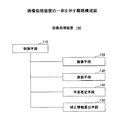
(画像処理装置の機能)
画像処理装置の機能の一例を、図2を用いて、説明する。図2は、画像処理装置の機能ブロック図である。
(Function of image processing device)
An example of the function of the image processing apparatus will be described with reference to FIG. FIG. 2 is a functional block diagram of the image processing apparatus.
図2において、制御手段110は、画像処理の動作を開始するため、撮像手段120に撮像の開始を指示する信号を出力する。
In FIG. 2, the
撮像手段120は、ステレオカメラによって、投影対象物を含む領域の像を撮像し、2つのカメラ画像データCimgを取得する。また、撮像手段120は、取得したカメラ画像データCimgを測距手段130に出力する。
The
測距手段130は、2つのカメラ画像データCimgに基づいて、投影対象物の外形表面上の複数の位置(以下、対応点という。)に対応する距離データを算出する。また、測距手段130は、距離データを平面推定手段140及び補正情報算出手段150に出力する。ここで、距離データとは、画像処理装置から投影対象物(対応点)までの距離に関するデータである。測距する方法の詳細は、後述の(測距する動作)で説明する。
The
平面推定手段140は、測距手段130が算出した距離データから、投影対象物に対応する平面として、回帰平面データを算出する。また、平面推定手段140は、回帰平面データを補正情報算出手段150に出力する。ここで、回帰平面データとは、三次元空間の複数の位置を含む平面に関するデータである。推定する方法の詳細は、後述の(平面を推定する動作)で説明する。
The
補正情報算出手段150は、測距手段130の距離データ及び平面推定手段140の回帰平面データに基づいて、コンテンツ画像データAimgの補正に関する情報を算出する。具体的には、補正情報算出手段150は、距離データ及び回帰平面データに基づいて、後述する凸包データC1(図8(b))を算出する。また、補正情報算出手段150は、凸包データに基づいて、仮想画像データVimgの台形歪み等をキャンセル(解消)するために、コンテンツ画像データAimgを補正するために必要な台形補正変換行列など(以下、補正に関する情報という。)を算出する。算出する方法の詳細は、後述の(補正情報を算出する動作)で説明する。
The correction
また、補正情報算出手段150は、制御手段110によって、図示しない投影手段等に補正に関する情報を出力する。 Further, the correction information calculation means 150 outputs information related to correction to the projection means (not shown) by the control means 110.
(測距する動作)
測距手段が、撮像手段のステレオカメラにより、撮像手段(画像処理装置)から対応点(投影対象物)までの距離に関する距離データを算出する動作を説明する。
(Ranging operation)
The operation in which the distance measuring means calculates distance data related to the distance from the imaging means (image processing apparatus) to the corresponding point (projection object) by the stereo camera of the imaging means will be described.
ここで、ステレオカメラとは、第1のカメラ(基準カメラ)及び第2のカメラ(参照カメラ)を有し、第1のカメラ及び第2のカメラは第1の撮像レンズ及び第2の撮像レンズ、並びに、第1の撮像レンズ及び第2の撮像レンズの背面側の方向(投影対象物の方向と反対側の方向)に配置された第1の撮像素子及び第2の撮像素子を有する。なお、撮像素子は、エリアセンサ、面センサ、及び、二次元センサ等を用いることができる。 Here, the stereo camera includes a first camera (reference camera) and a second camera (reference camera), and the first camera and the second camera are a first imaging lens and a second imaging lens. And a first imaging element and a second imaging element which are arranged in the direction of the back side of the first imaging lens and the second imaging lens (direction opposite to the direction of the projection object). As the image sensor, an area sensor, a surface sensor, a two-dimensional sensor, or the like can be used.
第1の撮像レンズと第2の撮像レンズとは、所定の間隔D(以下、基線長という。)で並設され、第1の撮像レンズの光軸と第2の撮像レンズの光軸とは平行である。また、第1の撮像素子等は、正面側(背面側の反対側)の表面上に、対象物の像を結像する受光面を備える。第1の撮像レンズ等の光軸等は、第1の撮像素子等の受光面の対角線の中心と一致するように位置決めされている。 The first imaging lens and the second imaging lens are juxtaposed at a predetermined distance D (hereinafter referred to as a baseline length), and the optical axis of the first imaging lens and the optical axis of the second imaging lens are Parallel. In addition, the first image sensor or the like includes a light receiving surface that forms an image of an object on the front surface (opposite the back surface). The optical axis of the first imaging lens or the like is positioned so as to coincide with the center of the diagonal line of the light receiving surface of the first imaging element or the like.
第1の撮像レンズを透過して入射した投影対象物の第1の像と第2の撮像レンズを透過して入射した投影対象物の第2の像とは、視差△だけ変位して、それぞれの受光面に結像される。撮像素子は、第1の像及び第2の像の光による明暗等を電荷の量に光電変換し、画素出力信号として、測距手段に出力する。このとき、測距手段は、画素出力信号を比較し、受光面の受光素子(画素)の位置(座標)から視差△を検出する。ここで、視差△、基線長D、画像処理装置と投影対象物との離間距離L、及び、撮像レンズの焦点距離fとすると、L>>fを条件に、数1が成り立つ(三角測量の原理)。
The first image of the projection object that has entered through the first imaging lens and the second image of the projection object that has entered through the second imaging lens are displaced by parallax Δ, respectively. An image is formed on the light receiving surface. The imaging device photoelectrically converts light and darkness of the first image and the second image by the amount of electric charge, and outputs the result as a pixel output signal to the distance measuring unit. At this time, the distance measuring means compares the pixel output signals and detects the parallax Δ from the position (coordinates) of the light receiving element (pixel) on the light receiving surface. Here, assuming that the parallax Δ, the base line length D, the separation distance L between the image processing apparatus and the projection object, and the focal length f of the imaging lens,

この場合、Dとfは既知である。 In this case, D and f are known.
測距手段は、検出した視差△から、数1により、離間距離Lを算出する。
The distance measuring means calculates the separation distance L from
次に、測距手段が、対応点の絶対座標(XYZ座標)を算出する動作を、具体的に説明する。ここで、X軸を基線長Dの方向、Y軸をX軸に直交する撮像素子の受光面上の方向、Z軸をX軸及びY軸に直交する方向(ステレオカメラの光軸方向)とする。また、第1のカメラ(添え字r)及び第2のカメラ(添え字l)の受光面に対する相対座標(xyz座標)を数2とする。 Next, the operation in which the distance measuring unit calculates the absolute coordinates (XYZ coordinates) of the corresponding points will be specifically described. Here, the X axis is the direction of the base length D, the Y axis is the direction on the light receiving surface of the image sensor orthogonal to the X axis, the Z axis is the direction orthogonal to the X axis and the Y axis (the optical axis direction of the stereo camera) To do. In addition, the relative coordinates (xyz coordinates) of the first camera (subscript r) and the second camera (subscript l) with respect to the light receiving surface are represented by Formula 2.
次に、対応点の座標P(絶対座標)を数4とする。 Next, the coordinate P (absolute coordinate) of the corresponding point is represented by Equation 4.
このとき、対応点の座標Pは、数1乃至数3より、数5となる。
At this time, the coordinate P of the corresponding point is expressed by Equation 5 from
以上により、測距手段は、撮像手段のステレオカメラを用いて、投影対象物の外形表面上の対応点の三次元座標(絶対座標)を算出し、その算出した三次元座標を対応点に関する距離データとして取得することができる。 As described above, the distance measuring means calculates the three-dimensional coordinates (absolute coordinates) of the corresponding points on the outer surface of the projection object using the stereo camera of the imaging means, and uses the calculated three-dimensional coordinates as the distances to the corresponding points. It can be acquired as data.
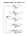
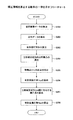
(平面を推定する動作)
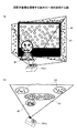
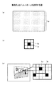
平面推定手段等が、投影対象物に対応する平面を推定する動作について、図3乃至図5を用いて説明する。図3は、平面推定手段等が平面を推定する動作の一例を示すフローチャートである。図4は、撮像手段が投影対象物を撮像する動作の一例を説明する図である。図5は、回帰分析によって、平面を推定する方法を説明する図である。
(Operation to estimate the plane)
An operation in which the plane estimation unit and the like estimate a plane corresponding to the projection object will be described with reference to FIGS. FIG. 3 is a flowchart showing an example of the operation of estimating the plane by the plane estimation means or the like. FIG. 4 is a diagram illustrating an example of an operation in which the imaging unit images the projection target object. FIG. 5 is a diagram for explaining a method for estimating a plane by regression analysis.
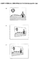
図3において、撮像手段は、投影対象物を含む領域を撮像し、カメラ画像データCimgを取得する(ステップS101)。ここで、撮像手段が撮像する動作を、図4を用いて、具体的に説明する。 In FIG. 3, the imaging means images a region including the projection target and acquires camera image data Cimg (step S101). Here, the operation of imaging by the imaging means will be specifically described with reference to FIG.
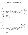
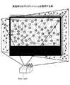
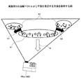
図4は、投影対象物を撮像する動作を示す。図4(a)は、画像が投影されている投影対象物などを正面方向から見た説明図である。図4(b)は、画像が投影されている投影対象物などを鉛直上方から見た説明図である。図中の○印は、投影対象物(スクリーン)A1表面上の位置(特徴点)を示す。図中の△印は、発表者A2の位置(特徴点)を示す。図中の×印は、投影対象物の背後の壁A3表面上の位置(特徴点)を示す。 FIG. 4 shows an operation for imaging a projection object. FIG. 4A is an explanatory view of a projection object on which an image is projected as seen from the front. FIG. 4B is an explanatory view of a projection target or the like on which an image is projected as viewed from above. The circles in the figure indicate positions (feature points) on the surface of the projection target (screen) A1. The Δ mark in the figure indicates the position (feature point) of the presenter A2. The x mark in the figure indicates the position (feature point) on the surface of the wall A3 behind the projection object.
図4において、発表者A2は、投影対象物A1の正面方向に立っている。また、壁A3が、投影対象物A1の背面方向(正面方向と反対側の方向)に近接している。このとき、プロジェクタに内蔵された撮像手段は、プロジェクタ(投影手段)などによりコンテンツ画像データAimgが投影された投影対象物A1を含む領域を撮像し、カメラ画像データCimgを取得する。 In FIG. 4, the presenter A2 stands in the front direction of the projection target A1. Further, the wall A3 is close to the back direction (the direction opposite to the front direction) of the projection target A1. At this time, the imaging unit built in the projector captures an area including the projection target A1 onto which the content image data Aimg is projected by a projector (projection unit) or the like, and acquires camera image data Cimg.
図3のステップS101において、カメラ画像データCimgの取得を完了すると、撮像手段は、カメラ画像データCimgを測距手段に出力する。その後、ステップS102に進む。 In step S101 in FIG. 3, when the acquisition of the camera image data Cimg is completed, the imaging unit outputs the camera image data Cimg to the distance measuring unit. Thereafter, the process proceeds to step S102.
ステップS102において、測距手段は、撮像手段から出力されたカメラ画像データCimgに基づいて、投影対象物を含む領域の特徴点(図4(a)及び(b)の○、△、及び、×)を抽出する。測距手段が特徴点を抽出する動作を具体的に説明する。 In step S102, the distance measuring means, based on the camera image data Cimg output from the imaging means, features points of the region including the projection object (◯, Δ, and × in FIGS. 4A and 4B). ). The operation of the distance measuring means to extract the feature points will be specifically described.
測距手段は、まず、ステレオカメラが取得した2つのカメラ画像データCimgの一方(以下、撮像データAという。)について、任意の画素を選択点として選択する。次に、測距手段は、撮像データAから、選択点とその選択点の周囲の8画素との画像情報(色、明るさ、及び、エッジ強度など)を比較する。このとき、選択点の画像情報が、その周囲の8画素の画像情報より、すべて大きい場合またはすべて小さい場合、その選択点を特徴点(xA,yA)として抽出する。また、測距手段は、その特徴点を中心とする一辺が15画素四方の範囲を、テンプレートブロックAとして抽出する。 The ranging means first selects an arbitrary pixel as a selection point for one of the two camera image data Cimg acquired by the stereo camera (hereinafter referred to as imaging data A). Next, the distance measuring means compares image information (color, brightness, edge strength, etc.) of the selected point and the eight pixels surrounding the selected point from the imaging data A. At this time, if the image information of the selected point is all larger or smaller than the image information of the surrounding eight pixels, the selected point is extracted as a feature point (x A , y A ). In addition, the distance measuring unit extracts a range having a side of 15 pixels around the feature point as a template block A.
特徴点の抽出を完了すると、ステップS103に進む。 When the feature point extraction is completed, the process proceeds to step S103.
なお、特徴点を抽出する方法は、上記の方法に限定されるものではない。上記の方法以外でも、投影対象物の表面上の特徴ある点を抽出できる方法であれば、いずれの方法も用いることができる。また、特徴点の具体例は、後述する実施例1及び実施例2において、説明する。 Note that the method of extracting feature points is not limited to the above method. In addition to the above method, any method can be used as long as it can extract a characteristic point on the surface of the projection target. Specific examples of feature points will be described in Example 1 and Example 2 described later.
ステップS103において、測距手段は、ステップS102で抽出された特徴点に基づいて、対応点を抽出する。測距手段が対応点を抽出する動作を、具体的に説明する。 In step S103, the distance measuring means extracts corresponding points based on the feature points extracted in step S102. The operation in which the distance measuring means extracts the corresponding points will be specifically described.
測距手段は、ステレオカメラが撮像した2つのカメラ画像データCimgの他方(以下、撮像データBという。)について、任意の画素を選択点(xB,yB)として選択する。また、測距手段は、その選択点を中心とする一辺が15画素四方の範囲を、テンプレートブロックBとして選択する。次に、測距手段は、テンプレートブロックA及びテンプレートブロックBの画像情報の総和を算出し、両者の総和を比較する。比較方法は、SAD及びSSDなどの方法を用いることができる。 The distance measuring means selects an arbitrary pixel as a selection point (x B , y B ) for the other of the two camera image data Cimg captured by the stereo camera (hereinafter referred to as imaging data B). In addition, the distance measuring unit selects, as the template block B, a range whose sides are 15 pixels square with the selected point as the center. Next, the distance measuring unit calculates the sum of the image information of the template block A and the template block B, and compares the sum of the two. As a comparison method, methods such as SAD and SSD can be used.
なお、SAD(Sum of Absolute Distance)とは、総和の比較において、絶対値の差分の総和を求める方法である。SSD(Squared Sum of Differences)とは、差分の2乗の総和を求める方法である。 Note that SAD (Sum of Absolute Distance) is a method for obtaining the sum of absolute value differences in the comparison of sums. SSD (Squared Sum of Differences) is a method for obtaining the sum of squares of differences.
次に、テンプレートブロックAとテンプレートブロックBとの比較の結果において、画像情報の総和の差分が最小値となるテンプレートブロックBの選択点(xB,yB)を選択する。このとき、その差分が所定の値以下であるとき、撮像データAの特徴点(xA,yA)と撮像データBの選択点(xB,yB)とが対応付けられ、その特徴点(xA,yA)(選択点(xB,yB))を対応点(xAB,yAB)として抽出する。 Next, a selection point (x B , y B ) of the template block B at which the difference of the sum of the image information is the minimum value is selected as a result of the comparison between the template block A and the template block B. At this time, when the difference is equal to or smaller than a predetermined value, the feature point (x A , y A ) of the imaging data A is associated with the selection point (x B , y B ) of the imaging data B, and the feature point (X A , y A ) (selected point (x B , y B )) is extracted as a corresponding point (x AB , y AB ).
ここで、所定の値とは、投影対象物と画像処理装置との離間距離、または、被写界深度に対応する値とすることができる。また、所定の値を、数値計算及び実験等により定められる値とすることができる。 Here, the predetermined value can be a distance corresponding to the projection object and the image processing apparatus or a value corresponding to the depth of field. Further, the predetermined value can be a value determined by numerical calculation, experiment, or the like.
測距手段は、対応点の抽出として、撮像データAから抽出されたすべての特徴点について、撮像データBの選択点と比較する。このとき、測距手段は、複数の対応点(以下、三次元点群という。)を抽出することになる。 The distance measuring means compares all the feature points extracted from the imaging data A with the selected points of the imaging data B as the corresponding points. At this time, the distance measuring means extracts a plurality of corresponding points (hereinafter referred to as a three-dimensional point group).
対応点の抽出を完了すると、ステップS104に進む。 When the extraction of the corresponding points is completed, the process proceeds to step S104.
ステップS104において、測距手段は、ステップS103で抽出された三次元点群の距離に関する距離データを算出する。距離データを算出する動作は、(測距する動作)と同様のため、説明を省略する。距離データの算出を完了すると、ステップS105に進む。 In step S104, the distance measuring unit calculates distance data related to the distance of the three-dimensional point group extracted in step S103. Since the operation for calculating the distance data is the same as (the operation for distance measurement), the description is omitted. When the calculation of the distance data is completed, the process proceeds to step S105.
ステップS105において、平面推定手段は、測距手段が算出した距離データに基づいて、投影対象物に対応する平面の情報として、回帰平面データを算出する。回帰平面データを算出する方法について、図5を用いて、具体的に説明する。 In step S105, the plane estimation unit calculates regression plane data as plane information corresponding to the projection target based on the distance data calculated by the distance measurement unit. A method for calculating the regression plane data will be specifically described with reference to FIG.
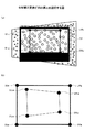
図5(a)は、回帰分析をした後の回帰平面P1を示す。図5(b)は、後述のステップS109で推定した平面から最も離れた対応点を除外した後の回帰平面P2を示す。 FIG. 5A shows the regression plane P1 after the regression analysis. FIG. 5B shows the regression plane P2 after excluding the corresponding point farthest from the plane estimated in step S109 described later.
図5(a)において、ステップS102乃至ステップS104により、三次元点群としてn個の対応点(XABi,YABi,ZABi)(i=1〜n)が算出されている(図中の○、△、及び×)。 In FIG. 5A, n corresponding points (X ABi , Y ABi , Z ABi ) (i = 1 to n) are calculated as a three-dimensional point group by steps S102 to S104 (in the drawing). (Circle), (triangle | delta), and x).
平面推定手段は、回帰分析によって、三次元点群から回帰平面を算出するため、回帰平面の方程式をz=ax+by+cと定義する。このとき、回帰平面と三次元点群とは、数6が成り立つ。 Since the plane estimation means calculates the regression plane from the three-dimensional point group by regression analysis, the regression plane equation is defined as z = ax + by + c. At this time, Equation 6 is established between the regression plane and the three-dimensional point group.
ここで、数6の変数は、数7である。 Here, the variable of Expression 6 is Expression 7.
数7において、eiは残差を示す。 In Equation 7, e i indicates a residual.
次に、正規方程式は、数8となる。 Next, the normal equation is expressed by Equation 8.
よって、βは、数9となる。 Therefore, β is given by Equation 9.
以上より、最小二乗法などを用いて、残差eiの平方和が最小となる定数(パラメータ)a、b、及び、cを算出することにより、回帰平面(図5(a)のP1及びP2)を求めることができる。平面推定手段は、回帰平面データとして、回帰平面の方程式(z=ax+by+c)の定数a、b、及び、cを取得する。回帰平面データの取得が完了すると、ステップS106に進む。 Thus, using the method of least squares, constants the sum of squares of residuals e i is minimized (parameter) a, b, and by calculating the c, P1 and the regression plane (FIGS. 5 (a) P2) can be determined. The plane estimation means acquires constants a, b, and c of the regression plane equation (z = ax + by + c) as the regression plane data. When the acquisition of the regression plane data is completed, the process proceeds to step S106.
次に、図3のステップS106において、回帰平面と三次元点群との距離DABiを算出し、回帰平面から最も離れた三次元点群の対応点PMAX(XABD,YABD,ZABD)とその距離DMAXを抽出する(図5(a)のPMAX)。具体的には、対応点(XABi,YABi,ZABi)から、平面(αx+βy+γz+δ=0)までの距離を、数10より、算出する。 Next, in step S106 of FIG. 3, a distance D ABi between the regression plane and the three-dimensional point group is calculated, and the corresponding point P MAX (X ABD , Y ABD , Z ABD ) of the three-dimensional point group farthest from the regression plane is calculated. ) And its distance D MAX (P MAX in FIG. 5A). Specifically, the distance from the corresponding point (X ABi , Y ABi , Z ABi ) to the plane (αx + βy + γz + δ = 0) is calculated from Equation 10.
回帰平面と三次元点群のすべての点との距離を算出し、その距離の絶対値が最大となる対応点を選択する。最も離れた対応点PMAX(XABD,YABD,ZABD)の抽出を完了すると、ステップS107に進む。 The distance between the regression plane and all points in the three-dimensional point group is calculated, and the corresponding point having the maximum absolute value of the distance is selected. When the extraction of the farthest corresponding point P MAX (X ABD , Y ABD , Z ABD ) is completed, the process proceeds to step S107.
ステップS107において、対応点PMAX(XABD,YABD,ZABD)に関する距離DMAXと所定の距離とを比較する。距離DMAXが所定の距離以下の場合は、ステップS108に進む。距離DMAXが所定の距離を越える場合は、ステップS109に進む。 In step S107, the distance D MAX relating to the corresponding point P MAX (X ABD , Y ABD , Z ABD ) is compared with a predetermined distance. If the distance D MAX is equal to or smaller than the predetermined distance, the process proceeds to step S108. If the distance D MAX exceeds the predetermined distance, the process proceeds to step S109.
ここで、所定の距離とは、投影対象物と画像処理装置との離間距離に対応する値とすることができ、数値計算及び実験等により、その距離を定めることができる。また、被写界深度に対応する値とすることができる。 Here, the predetermined distance can be a value corresponding to the separation distance between the projection target and the image processing apparatus, and the distance can be determined by numerical calculation, experiment, or the like. Moreover, it can be set as the value corresponding to the depth of field.
ステップS108において、算出した回帰平面(ステップS105)を投影対象物に対応する平面と推定し、回帰平面データとして記憶する。その後、図中の「END」に進み、平面の推定を終了する。 In step S108, the calculated regression plane (step S105) is estimated as a plane corresponding to the projection object, and stored as regression plane data. Thereafter, the process proceeds to “END” in the drawing, and the estimation of the plane is finished.
ステップS109において、対応点PMAX(XABD,YABD,ZABD)を三次元点群から除外する。除外を完了すると、ステップS105に戻り、ステップS105乃至S107を繰り返し、再度、回帰平面P2を推定する(図5(b))。 In step S109, the corresponding point P MAX (X ABD , Y ABD , Z ABD ) is excluded from the three-dimensional point group. When the exclusion is completed, the process returns to step S105, steps S105 to S107 are repeated, and the regression plane P2 is estimated again (FIG. 5B).
以上より、本発明の画像処理装置は、画像処理装置から投影対象物までの距離を測定し、回帰分析によって、投影対象物に対応する平面を推定することができる。また、本発明の画像処理装置は、平面からの距離が所定の距離を越える対応点を除外することによって、画像処理装置と投影対象物との間に障害物があるとき、あるいは、投影対象物の背後に壁などが近接しているときでも、投影対象物に対応する平面を推定することができる。 As described above, the image processing apparatus of the present invention can measure the distance from the image processing apparatus to the projection object and estimate the plane corresponding to the projection object by regression analysis. Further, the image processing apparatus of the present invention excludes corresponding points whose distance from the plane exceeds a predetermined distance, so that there is an obstacle between the image processing apparatus and the projection object, or the projection object Even when a wall or the like is close to the back of the object, the plane corresponding to the projection object can be estimated.
なお、平面を推定する動作において、除外する対応点は障害物及び背後の壁などに関するものに限定されるものではなく、投影対象物以外のものを含むことができる。また、平面を推定する際に用いる三次元点群は、(測距する動作)で抽出した三次元点群から「ランダムに選択した複数の点」と「ランダムに選択した複数の点」以外の点群とから成る平面の定数(パラメータ)を算出し、その定数の差分が小さい点群を用いて、平面を推定することができる。 In addition, in the operation of estimating the plane, the corresponding points to be excluded are not limited to those related to the obstacle and the back wall, but can include things other than the projection target. In addition, the 3D point cloud used when estimating the plane is other than “randomly selected points” and “randomly selected points” from the 3D point cloud extracted in (ranging operation). A constant (parameter) of a plane composed of the point group is calculated, and the plane can be estimated using a point group having a small difference between the constants.
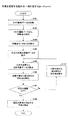
(補正情報を算出する動作)
補正情報算出手段が、補正の情報を算出する動作ついて、図6乃至図9を用いて、説明する。
(Operation to calculate correction information)
The operation in which the correction information calculation means calculates the correction information will be described with reference to FIGS.
図6は、補正情報を算出する動作の一例を示すフローチャートである。図7は、仮想カメラから仮想画像データを取得する動作を説明する図である。図8は、仮想画像データを説明する図である。図9は、台形補正変換行列の算出を説明する図である。 FIG. 6 is a flowchart illustrating an example of an operation for calculating correction information. FIG. 7 is a diagram illustrating an operation of acquiring virtual image data from a virtual camera. FIG. 8 is a diagram for explaining virtual image data. FIG. 9 is a diagram for explaining the calculation of the trapezoidal correction conversion matrix.
図6において、補正情報算出手段は、平面推定手段が推定した平面の正面方向から撮像したと仮定した場合の、カメラ画像データCimgに関する画像データ(仮想画像データVimg)を算出する(ステップS201)。補正情報算出手段が仮想画像データVimgを算出する動作を、図7を用いて、具体的に説明する。 In FIG. 6, the correction information calculation unit calculates image data (virtual image data Vimg) related to the camera image data Cimg when it is assumed that the image is taken from the front direction of the plane estimated by the plane estimation unit (step S201). The operation in which the correction information calculation means calculates the virtual image data Vimg will be specifically described with reference to FIG.
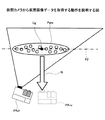
図7は、推定した平面における三次元点群Pgrpの中心(重心)位置Cgからその平面の法線方向Nの延長線上に仮想カメラ(撮像手段を含むプロジェクタなど)PRJvを配置したと仮定することを示す。 FIG. 7 assumes that a virtual camera (such as a projector including an imaging unit) PRJv is arranged on an extension line in the normal direction N of the plane from the center (center of gravity) position Cg of the three-dimensional point group Pgrp on the estimated plane. Indicates.
図7において、実際のカメラ(撮像手段を含むプロジェクタなど)PRJrが、コンテンツ画像データAimgを投影する。このとき、実際のカメラPRJrに搭載された撮像手段がカメラ画像データCimgを取得し、測距手段が三次元点群Pgrpの距離データを取得し、平面推定手段が平面P2を推定する。 In FIG. 7, an actual camera (such as a projector including an imaging unit) PRJr projects content image data Aimg. At this time, the imaging means mounted on the actual camera PRJr acquires the camera image data Cimg, the distance measurement means acquires the distance data of the three-dimensional point group Pgrp, and the plane estimation means estimates the plane P2.
補正情報算出手段は、平面P2の法線方向Nの延長線上の仮想カメラPRJvから撮像される仮想画像データVimgを算出する。具体的には、補正情報算出手段は、透視投影変換行列Pを用いて、三次元点群Pgrpを二次元の平面(仮想カメラPRJvから撮像される仮想画像データVimgに対応する平面)に投影して、仮想画像データVimgを算出する。 The correction information calculation means calculates virtual image data Vimg captured from the virtual camera PRJv on the extension line in the normal direction N of the plane P2. Specifically, the correction information calculation means projects the three-dimensional point group Pgrp onto a two-dimensional plane (a plane corresponding to the virtual image data Vimg captured from the virtual camera PRJv) using the perspective projection transformation matrix P. Thus, the virtual image data Vimg is calculated.
ここで、透視投影変換行列Pとは、内部パラメータをAとし、外部パラメータである回転行列をR、平行移動ベクトルをtとすると、数11となる。 Here, the perspective projection transformation matrix P is expressed by Equation 11 where A is an internal parameter, R is a rotation matrix that is an external parameter, and t is a translation vector.
ここで、内部パラメータAとは、仮想カメラPRJvの光軸座標、撮像素子の行と列のスケール、焦点距離fなどを用いて定められる行列(3×3)である。回転行列Rとは、実際のカメラPRJrから仮想カメラPRJvまでの回転を示す行列(3×3)である。平行移動ベクトルtとは、実際のカメラPRJrから仮想カメラPRJvまでの平行移動を示すベクトル(3×1)である。 Here, the internal parameter A is a matrix (3 × 3) determined by using the optical axis coordinates of the virtual camera PRJv, the scale of the row and column of the image sensor, the focal length f, and the like. The rotation matrix R is a matrix (3 × 3) indicating the rotation from the actual camera PRJr to the virtual camera PRJv. The translation vector t is a vector (3 × 1) indicating translation from the actual camera PRJr to the virtual camera PRJv.
仮想画像データVimgの算出を完了すると、ステップS202に進む。 When the calculation of the virtual image data Vimg is completed, the process proceeds to step S202.
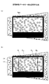
次に、図6のステップS202において、補正情報算出手段は、算出した仮想画像データVimgにおける凸包データを算出する。ここで、凸包データとは、三次元点群において、平面推定手段が推定した平面上にある測距手段が算出した複数の対応点を包み込む多角形(以下、凸包という。)に関するデータである。凸包データを算出する方法を、図8を用いて、具体的に説明する。 Next, in step S202 of FIG. 6, the correction information calculation means calculates convex hull data in the calculated virtual image data Vimg. Here, the convex hull data is data regarding a polygon (hereinafter referred to as a convex hull) that wraps a plurality of corresponding points calculated by the distance measuring means on the plane estimated by the plane estimating means in the three-dimensional point group. is there. A method for calculating the convex hull data will be specifically described with reference to FIG.
図8は、仮想カメラPRJvが取得する仮想画像データVimgを説明する図である。図8(a)は、仮想画像データVimgにおける対応点を説明する図である。図8(b)は、凸包データ及び後述する台形補正矩形を説明する図である。 FIG. 8 is a diagram illustrating virtual image data Vimg acquired by the virtual camera PRJv. FIG. 8A is a diagram for explaining corresponding points in the virtual image data Vimg. FIG. 8B is a diagram for explaining convex hull data and a trapezoidal correction rectangle described later.
図8(a)において、補正情報算出手段は、仮想カメラPRJvが取得した仮想画像データVimgにおいて、測距手段が算出した距離データに基づいて、平面推定手段が推定した平面上にある複数の対応点(図中の○、図7の三次元点群Pgrp)を抽出する。次に、図8(b)において、補正情報算出手段は、抽出した複数の対応点について、その対応点を包み込む凸包に関する凸包データを算出する。このとき、凸包は、図中の○印を含む多角形C1である。 In FIG. 8A, the correction information calculation means includes a plurality of correspondences on the plane estimated by the plane estimation means based on the distance data calculated by the distance measurement means in the virtual image data Vimg acquired by the virtual camera PRJv. A point (◯ in the figure, three-dimensional point group Pgrp in FIG. 7) is extracted. Next, in FIG. 8B, the correction information calculation means calculates convex hull data relating to the convex hull that wraps the corresponding points for the extracted corresponding points. At this time, the convex hull is a polygon C1 including a circle in the figure.
凸包データの算出を完了すると、ステップS203に進む。 When the calculation of the convex hull data is completed, the process proceeds to step S203.
次に、図6のステップS203において、補正情報算出手段は、仮想画像データVimgにおける台形補正矩形を算出する。ここで、台形補正矩形とは、ステップ202で算出した凸包C1に包含される最大面積の矩形である。補正情報算出手段は、アスペクト比を固定して、凸包C1が包含する台形補正矩形C2を算出する(図8(b))。アスペクト比は、プロジェクタ画像データPimgに関する画像のアスペクト比と同一とすることができる。例えば、1600×1200ピクセルの画像を投影する場合は、アスペクト比を4:3とすることができる。 Next, in step S203 of FIG. 6, the correction information calculation unit calculates a trapezoid correction rectangle in the virtual image data Vimg. Here, the trapezoidal correction rectangle is a rectangle having the maximum area included in the convex hull C1 calculated in step 202. The correction information calculation means calculates the trapezoid correction rectangle C2 included in the convex hull C1 while fixing the aspect ratio (FIG. 8B). The aspect ratio can be the same as the aspect ratio of the image related to the projector image data Pimg. For example, when an image of 1600 × 1200 pixels is projected, the aspect ratio can be 4: 3.
台形補正矩形の算出を完了すると、ステップS204に進む。 When the calculation of the trapezoidal correction rectangle is completed, the process proceeds to step S204.
図6のステップS204において、補正情報算出手段は、台形補正矩形C2内の任意の4点(図8(b)のMV1乃至MV4)を特徴点として選択する。ここで、任意の4点は、仮想画像データVimgに関する投影光の4隅の点とすることができる。この場合、特徴点が少ない(または、特徴点を抽出できない)画像を投影しているときでも、4隅の点を特徴点として抽出することができる。特徴点の選択を完了すると、ステップS205に進む。 In step S204 of FIG. 6, the correction information calculation means selects any four points (M V1 to M V4 in FIG. 8B) in the trapezoidal correction rectangle C2 as feature points. Here, the arbitrary four points can be the four corner points of the projection light related to the virtual image data Vimg. In this case, even when an image with few feature points (or feature points cannot be extracted) is projected, the four corner points can be extracted as feature points. When selection of the feature points is completed, the process proceeds to step S205.
ステップS205において、補正情報算出手段は、特徴点(MV1乃至MV4)に対応するコンテンツ画像データAimgの対応点を抽出する。対応点を抽出する動作は、(測距する動作)と同様のため、説明を省略する。対応点の抽出を完了すると、ステップS206に進む。 In step S205, the correction information calculation means extracts the corresponding points of the content image data Aimg corresponding to the feature points (M V1 to M V4 ). The operation for extracting the corresponding points is the same as the (ranging operation), and the description is omitted. When the extraction of the corresponding points is completed, the process proceeds to step S206.
ステップS206において、補正情報算出手段は、射影変換行列Hcpを算出する。具体的には、仮想画像データVimgに関する画像上の特徴点mVi(xVi、yVi)に対応するコンテンツ画像データAimgに関する画像上の4点の対応点をmai=(xai、yai)(i=1〜4)とすると、射影変換行列Hcpと数12が成り立つ。 In step S206, the correction information calculation means calculates a projective transformation matrix Hcp. Specifically, four corresponding points on the image relating to the content image data Aimg corresponding to the feature point m Vi (x Vi , y Vi ) on the image relating to the virtual image data Vimg are represented by m ai = (x ai , y ai ) (I = 1 to 4), the projective transformation matrix Hcp and Equation 12 hold.
ここで、数12の右辺と左辺とは、同次座標系で等しい(全成分の定数倍以外は等しい)ことを示す。また、射影変換行列Hcpは次式である。 Here, the right side and the left side of Equation 12 are equal in the homogeneous coordinate system (except for a constant multiple of all components). Further, the projective transformation matrix Hcp is the following equation.
このとき数12は、数14と表すことができる。 At this time, Expression 12 can be expressed as Expression 14.
数14の第3成分を1にあわせるため、右辺を正規化すると、数15となる。 When the right side is normalized in order to adjust the third component of Equation 14 to 1, Equation 15 is obtained.
ここで、h1乃至h8は未知係数である。仮想画像データVimgに関する画像上の特徴点MVi(xVi、yVi)に対応するコンテンツ画像データAimgに関する画像上の対応点Mai(xai、yai)の4つの組合せを得ることで、h1乃至h8を算出することができる。その結果、h1乃至h8を用いて、射影変換行列Hcpを算出することができる。 Here, h 1 to h 8 are unknown coefficients. By obtaining four combinations of corresponding points M ai (x ai , y ai ) on the image relating to the content image data Aimg corresponding to the feature points M Vi (x Vi , y Vi ) on the image relating to the virtual image data Vimg, h 1 to h 8 can be calculated. As a result, the projective transformation matrix Hcp can be calculated using h 1 to h 8 .
射影変換行列Hcpの算出を完了すると、ステップS207に進む。 When the calculation of the projective transformation matrix Hcp is completed, the process proceeds to step S207.
ステップS207において、補正情報算出手段は、ステップS203の台形補正矩形C2の4隅に対応するコンテンツ画像データAimgに関する4つの補正点を算出する。補正点を算出する方法を、図9を用いて、具体的に説明する。 In step S207, the correction information calculation means calculates four correction points related to the content image data Aimg corresponding to the four corners of the trapezoid correction rectangle C2 in step S203. A method of calculating the correction point will be specifically described with reference to FIG.
図9は、仮想画像データVimgとプロジェクタ画像データPimgの関係を説明する図である。図9(a)は、仮想画像データVimgに関する画像上の台形補正矩形の4隅の点を説明する図である。図9(b)は、コンテンツ画像データAimgに関する画像上の4つの補正点を説明する図である。 FIG. 9 is a diagram for explaining the relationship between virtual image data Vimg and projector image data Pimg. FIG. 9A is a diagram illustrating the four corner points of the trapezoidal correction rectangle on the image relating to the virtual image data Vimg. FIG. 9B is a diagram for explaining four correction points on the image related to the content image data Aimg.
図9(a)において、ステップS203で算出した台形補正矩形C2の4隅の点(図中のURv、ULv、DRv、及び、DLv)を抽出する。次に、図9(b)において、4隅の点に対応するコンテンツ画像データAimgに関する画像上の4つの補正点(図中のURva、ULva、DRva、及び、DLva)を、ステップS206で算出した射影変換行列Hcpを用いて、算出する。 In FIG. 9A, the four corner points (URv, ULv, DRv, and DLv in the figure) of the trapezoidal correction rectangle C2 calculated in step S203 are extracted. Next, in FIG. 9B, four correction points (URva, ULva, DRva, and DLva in the figure) on the image relating to the content image data Aimg corresponding to the four corner points are calculated in step S206. Calculation is performed using the projective transformation matrix Hcp.
4つの補正点の算出を完了すると、ステップS208に進む。 When the calculation of the four correction points is completed, the process proceeds to step S208.
図6のステップS208において、補正情報算出手段は、コンテンツ画像データAimgに関する画像の4隅の点(図9(b)のURa等)を、ステップS207で算出した4つの補正点(URva等)に変形(補正)する台形補正変換行列Hppを算出する。台形補正変換行列Hppを算出する方法は、ステップS206と同様のため、説明を省略する。 In step S208 in FIG. 6, the correction information calculation means converts the four corner points (such as URa in FIG. 9B) of the image relating to the content image data Aimg to the four correction points (such as URva) calculated in step S207. A trapezoidal correction conversion matrix Hpp to be deformed (corrected) is calculated. The method for calculating the trapezoid correction conversion matrix Hpp is the same as that in step S206, and thus the description thereof is omitted.
台形補正変換行列Hppの算出を完了すると、台形補正変換行列Hppを補正に関する情報として記憶し、図中の「END」に進み、補正情報を算出する動作を終了する。 When the calculation of the trapezoidal correction conversion matrix Hpp is completed, the trapezoidal correction conversion matrix Hpp is stored as information relating to correction, the process proceeds to “END” in the figure, and the operation for calculating the correction information is terminated.
なお、この台形補正変換行列Hppに基づいて、コンテンツ画像データAimgを補正し、台形歪み等がキャンセル(解消)されたプロジェクタ画像データPimgを生成することができる。 Note that, based on the trapezoidal correction conversion matrix Hpp, the content image data Aimg can be corrected to generate projector image data Pimg in which trapezoidal distortion and the like are canceled (resolved).
以上より、補正情報算出手段は、距離データ、回帰平面データ、及び、凸包データ等に基づいて、投影される画像の台形歪み等を解消するために必要な補正に関する情報を算出することができる。 As described above, the correction information calculation means can calculate information related to correction necessary for eliminating trapezoidal distortion and the like of the projected image based on distance data, regression plane data, convex hull data, and the like. .
(プログラム、及び、そのプログラムを記録した記録媒体)
本発明のプログラムPrは、撮像手段により、画像が投影されている対象物を含む領域を撮像して、画像データを取得する工程と、画像データに基づき、撮像手段と対象物との離間距離に関する距離データを算出する工程と、距離データから、対象物に対応する平面を推定する工程と、距離データと平面に関する情報とに基づき、投影する画像の補正に関する情報を算出する工程と、を実行する。
(Program and recording medium recording the program)
The program Pr of the present invention relates to a step of capturing an image including an object on which an image is projected by an image capturing unit to acquire image data, and a separation distance between the image capturing unit and the object based on the image data. Executing a step of calculating distance data, a step of estimating a plane corresponding to the object from the distance data, and a step of calculating information on correction of an image to be projected based on the distance data and information on the plane. .
この構成によれば、本発明の画像処理装置と同等の効果が得られる。 According to this configuration, an effect equivalent to that of the image processing apparatus of the present invention can be obtained.
また、本発明は、プログラムPrを記録したコンピュータによって読み取り可能な記録媒体Mdとしてもよい。このプログラムPrを記録した記録媒体Mdとしては、フレキシブルディスク、CD−ROM、及び、メモリーカード等、コンピュータ読み取り可能な媒体を利用することができる。 Further, the present invention may be a recording medium Md that can be read by a computer in which the program Pr is recorded. As the recording medium Md on which the program Pr is recorded, a computer-readable medium such as a flexible disk, a CD-ROM, and a memory card can be used.
(実施例)
プロジェクタの実施例を用いて、本発明の画像処理装置及び画像処理方法を説明する。
(Example)
An image processing apparatus and an image processing method of the present invention will be described using an embodiment of a projector.
本発明の画像処理装置等は、プロジェクタに用いられる画像処理装置等に限定されるものではない。プロジェクタ以外でも、対象物を含む領域を撮像した画像を画像処理することにより、投影する画像の補正に関する情報を算出するものであれば、いずれにも用いることができる。 The image processing apparatus and the like of the present invention are not limited to the image processing apparatus and the like used for the projector. Any projector other than a projector can be used as long as it calculates information regarding correction of an image to be projected by performing image processing on an image obtained by imaging an area including an object.
実施例1のプロジェクタを用いて、本発明を説明する。 The present invention will be described using the projector according to the first embodiment.
(プロジェクタの構成)
図10は、本実施例のプロジェクタの概略構成図の一例である。
(Projector configuration)
FIG. 10 is an example of a schematic configuration diagram of the projector according to the present embodiment.
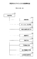
図10において、プロジェクタ200は、本実施例では、投影手段210、オートフォーカス手段220、及び、投影用画像生成手段230を含む。また、プロジェクタ200は、画像処理装置として、制御手段110、撮像手段120、測距手段130、平面推定手段140、補正情報算出手段150、及び、位置移動判断手段160を含む。
10, the
プロジェクタ200は、投影対象物に画像を投影し、投影対象物を含む領域を撮像し、投影対象物に対応する平面を推定する。また、プロジェクタは、推定した平面等に基づいて、投影用レンズのフォーカスを調整し、投影する画像を補正する。
The
ここで、投影手段210とは、プロジェクタの投影用レンズから投影対象物に画像を投影する手段である。オートフォーカス手段220とは、投影対象物にプロジェクタの投影用レンズのフォーカスを合わせる手段である。投影用画像生成手段230とは、プロジェクタが投影する画像を生成する手段である。
Here, the projecting
画像処理装置の位置移動判断手段160は、プロジェクタと投影対象物との位置に関する関係が変化したか否か(プロジェクタ及び/または投影対象物が移動したか否か)を判断する手段である。画像処理装置の制御手段110等は、図1と同様のため、説明を省略する。
The position
(投影を校正する動作)
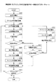
プロジェクタが、投影する画像を校正する動作について、図11乃至図13を用いて説明する。図11は、本実施例のプロジェクタの投影動作の一例を示すフローチャートである。図12は、投影された画像の特徴点及び対応点の抽出を説明する図である。図13は、投影する画像の補正を説明する図である。
図11において、プロジェクタの制御手段は、操作パネル等からの入力により、画像を投影する動作の校正を開始するため、投影手段等に動作の指示を出力する(ステップS301)。その後、ステップS302に進む。
(Operation to calibrate the projection)
An operation in which the projector calibrates an image to be projected will be described with reference to FIGS. FIG. 11 is a flowchart showing an example of the projection operation of the projector of this embodiment. FIG. 12 is a diagram for explaining extraction of feature points and corresponding points of a projected image. FIG. 13 is a diagram for explaining correction of an image to be projected.
In FIG. 11, the control unit of the projector outputs an operation instruction to the projection unit or the like in order to start calibration of the operation of projecting an image by an input from the operation panel or the like (step S301). Thereafter, the process proceeds to step S302.
ステップS302において、投影手段は、コンテンツ画像データAimgをプロジェクタ画像データPimgとして、投影用レンズから投影対象物に画像を投影する。その後、ステップS303に進む。 In step S302, the projecting unit projects the image from the projection lens onto the projection object using the content image data Aimg as the projector image data Pimg. Thereafter, the process proceeds to step S303.
ステップS303において、撮像手段は、投影対象物を含む領域を撮像し、カメラ画像データCimgを取得する。取得を完了すると、ステップS304に進む。 In step S303, the imaging unit captures an area including the projection target and acquires camera image data Cimg. When the acquisition is completed, the process proceeds to step S304.
ステップS304において、測距手段は、カメラ画像データCimgに基づいて、プロジェクタ(撮像手段)から投影対象物(対応点)までの距離を算出する。距離を算出する方法を、図12を用いて、具体的に説明する。 In step S304, the distance measuring unit calculates the distance from the projector (imaging unit) to the projection target (corresponding point) based on the camera image data Cimg. A method of calculating the distance will be specifically described with reference to FIG.
図12は、投影する画像の特徴点及び対応点を示す。図12(a)は、コンテンツ画像データAimgに関する画像を示す。図12(b)は、撮像手段のステレオカメラの基準カメラが取得したカメラ画像データCimgに関する画像を示す。図12(c)は、参照カメラが取得したカメラ画像データCimgに関する画像を示す。 FIG. 12 shows feature points and corresponding points of an image to be projected. FIG. 12A shows an image related to the content image data Aimg. FIG. 12B shows an image related to the camera image data Cimg acquired by the reference camera of the stereo camera of the imaging unit. FIG. 12C shows an image related to the camera image data Cimg acquired by the reference camera.
図12(a)において、コンテンツ画像データAimgに関する画像の特徴点を示す(図中の○)。測距手段は、基準カメラ及び参照カメラのカメラ画像データCimgに関する画像から、特徴点(図12(a))に対応する対応点(図12(b)及び図12(c)の○)に関する視差△を算出する。次に、測距手段は、対応点の絶対座標(XYZ座標)を算出し、第1の距離データDd1を取得する。ここで、対応点の絶対座標を算出する方法は、前述の(測距する動作)と同様であるため、説明を省略する。第1の距離データDd1の取得を完了すると、ステップS305に進む。 In FIG. 12A, image feature points relating to the content image data Aimg are shown (◯ in the figure). The distance measuring means, from the images related to the camera image data Cimg of the standard camera and the reference camera, parallax regarding the corresponding point (◯ in FIG. 12B and FIG. 12C) corresponding to the feature point (FIG. 12A) Δ is calculated. Next, the distance measuring means calculates absolute coordinates (XYZ coordinates) of the corresponding points, and obtains first distance data Dd1. Here, since the method of calculating the absolute coordinates of the corresponding points is the same as the above-described (ranging operation), the description thereof is omitted. When the acquisition of the first distance data Dd1 is completed, the process proceeds to step S305.
図11のステップS305において、平面推定手段は、取得した第1の距離データDd1に基づいて、投影対象物に対応する平面を推定する。ここで、平面の推定方法は、前述の(平面を推定する動作)と同様であるため、説明を省略する。平面の推定を完了すると、ステップS306に進む。 In step S305 in FIG. 11, the plane estimation means estimates a plane corresponding to the projection target based on the acquired first distance data Dd1. Here, since the plane estimation method is the same as the above-described (operation for estimating a plane), the description thereof is omitted. When the estimation of the plane is completed, the process proceeds to step S306.
ステップS306において、制御手段は、投影する動作の校正が、初回(プロジェクタの電源を入れてから最初の校正)であるか否かを判断する。初回の場合は、ステップS307に進む。それ以外の場合は、ステップS312に進む。 In step S306, the control unit determines whether or not the calibration of the projection operation is the first time (the first calibration after the projector is turned on). If it is the first time, the process proceeds to step S307. Otherwise, the process proceeds to step S312.
ステップS307において、補正情報算出手段は、撮像手段が取得したカメラ画像データCimgと平面推定手段が推定した平面に基づいて、仮想画像データVimgを算出する。また、補正情報算出手段は、仮想画像データVimgと距離データとに基づいて、プロジェクタ画像データPimgの補正に関する情報(台形補正変換行列Hppなど)を算出する。補正に関する情報を算出する方法を、図13を用いて、具体的に説明する。 In step S307, the correction information calculation unit calculates virtual image data Vimg based on the camera image data Cimg acquired by the imaging unit and the plane estimated by the plane estimation unit. Further, the correction information calculation means calculates information (such as a trapezoid correction conversion matrix Hpp) related to the correction of the projector image data Pimg based on the virtual image data Vimg and the distance data. A method for calculating information related to correction will be specifically described with reference to FIG.
図13は、投影する画像の補正する動作を説明する図である。図13(a)は、補正前の仮想画像データVimgに関する画像を示す。図13(b)は、補正後のプロジェクタ画像データPimgに関する画像を示す。図13(c)は、補正後の仮想画像データVimgに関する画像を示す。 FIG. 13 is a diagram for explaining an operation for correcting an image to be projected. FIG. 13A shows an image related to the virtual image data Vimg before correction. FIG. 13B shows an image related to the corrected projector image data Pimg. FIG. 13C shows an image related to the corrected virtual image data Vimg.
図13(a)において、補正情報算出手段は、カメラ画像データCimgと推定した平面に基づいて、仮想画像データVimgに関する画像を生成する。また、補正情報算出手段は、仮想画像データVimgに関する画像に基づいて、凸包C1及び台形補正矩形C2を算出する。次に、図13(b)において、補正情報算出手段は、凸包C1及び台形補正矩形C2に基づいて、射影変換行列Hcp及び台形補正変換行列Hppを算出する。ここで、射影変換行列Hcp等を算出する方法は、前述の(補正情報を算出する動作)と同様であるため、説明を省略する。 In FIG. 13A, the correction information calculation means generates an image related to the virtual image data Vimg based on the estimated plane of the camera image data Cimg. In addition, the correction information calculation unit calculates the convex hull C1 and the trapezoid correction rectangle C2 based on the image related to the virtual image data Vimg. Next, in FIG. 13B, the correction information calculation means calculates a projective transformation matrix Hcp and a trapezoidal correction conversion matrix Hpp based on the convex hull C1 and the trapezoidal correction rectangle C2. Here, since the method for calculating the projective transformation matrix Hcp and the like is the same as the above-described (operation for calculating correction information), the description thereof is omitted.
算出を完了すると、ステップS308に進む。 When the calculation is completed, the process proceeds to step S308.
図11のステップS308において、オートフォーカス手段は、算出した第1の距離データDd1(ステップS304)及び/または推定した平面(ステップS305)に関する情報に基づいて、投影用レンズの移動により、投影対象物に投影用レンズのフォーカスを合わせる。ここで、合焦方法について、投影された領域の中心に位置に対する投影対象物の距離に関する第1の距離データDd1を測距手段により算出し、その算出した第1の距離データDd1に基づいて、フォーカスを調整することができる。中心の位置は、三次元点群のX座標とY座標の最大値と最小値を示す点(位置)の平均値としてもよい。または、三次元点群のすべての点の平均値(または重心)としてもよい。 In step S308 of FIG. 11, the autofocus unit performs the projection object by moving the projection lens based on the information about the calculated first distance data Dd1 (step S304) and / or the estimated plane (step S305). Adjust the focus of the projection lens. Here, with respect to the focusing method, first distance data Dd1 relating to the distance of the projection object with respect to the position at the center of the projected area is calculated by the distance measuring means, and based on the calculated first distance data Dd1, The focus can be adjusted. The center position may be an average value of points (positions) indicating the maximum and minimum values of the X and Y coordinates of the three-dimensional point group. Or it is good also as an average value (or gravity center) of all the points of a three-dimensional point group.
合焦を完了すると、ステップS309に進む。 When focusing is completed, the process proceeds to step S309.
図11のステップS309において、投影用画像生成手段は、投影するプロジェクタ画像データPimgに関する画像を補正する。具体的には、投影用画像生成手段は、算出した台形補正変換行列Hppに基づいて、コンテンツ画像データAimgに関する画像を補正(変形)し、台形歪み等が解消されるプロジェクタ画像データPimgに関する画像を生成する(図13(b))。この補正後のプロジェクタ画像データPimgを投影したときの仮想画像データVimgに関する画像が図13(c)であり、投影対象物の正面方向から見た場合に台形歪みがキャンセル(解消)された画像となる。 In step S309 in FIG. 11, the projection image generation unit corrects an image related to the projector image data Pimg to be projected. Specifically, the projection image generation unit corrects (deforms) an image related to the content image data Aimg based on the calculated trapezoidal correction conversion matrix Hpp, and an image related to the projector image data Pimg from which the trapezoidal distortion or the like is eliminated. Generate (FIG. 13B). FIG. 13C shows an image related to the virtual image data Vimg when the projector image data Pimg after the correction is projected, and an image in which the trapezoidal distortion is canceled (resolved) when viewed from the front direction of the projection object. Become.
補正を完了すると、ステップS310に進む。 When the correction is completed, the process proceeds to step S310.
ステップS310において、制御手段は、所定の時間間隔を測定するタイムカウンタなどにより、所定の時間を経過したか否かを判断する。所定の時間を経過するとタイムカウンタなどをリセットし、ステップS311に進む。所定の時間の未経過のときは、所定の時間を経過するまで待機する。 In step S310, the control means determines whether or not a predetermined time has passed by using a time counter or the like that measures a predetermined time interval. When a predetermined time elapses, the time counter and the like are reset, and the process proceeds to step S311. If the predetermined time has not elapsed, the system waits until the predetermined time elapses.
ステップS311において、制御手段は、プロジェクタが使用中か否かを判断する。プロジェクタが使用中の場合は、所定の時間間隔で投影する動作を校正するため、ステップS303に戻る。それ以外の場合は、図中の「END」に進み、校正等の動作を終了する。 In step S311, the control unit determines whether the projector is in use. When the projector is in use, the process returns to step S303 in order to calibrate the operation of projecting at a predetermined time interval. In other cases, the process proceeds to “END” in the figure, and the operation such as calibration is terminated.
ステップS312において、位置移動判断手段は、プロジェクタと投影対象物との位置に関する関係の変化量を算出する。具体的には、位置移動判断手段は、平面推定手段により新たに平面を推定し、前回推定した平面と新たに推定した平面の比較に基づいて、位置に関する関係(離間距離、水平角、仰角など)の変化量を算出することができる。また、位置移動判断手段は、推定した平面に基づく台形補正矩形の重心(中心)の位置の移動量を変化量とすることができる。 In step S312, the position movement determination unit calculates the amount of change in the relationship regarding the position between the projector and the projection target. Specifically, the position movement determination means estimates a new plane by the plane estimation means, and based on a comparison between the previously estimated plane and the newly estimated plane, the positional relationship (separation distance, horizontal angle, elevation angle, etc.) ) Can be calculated. Further, the position movement determination means can set the movement amount of the position of the center of gravity (center) of the trapezoidal correction rectangle based on the estimated plane as the change amount.
算出を完了すると、ステップS313に進む。 When the calculation is completed, the process proceeds to step S313.
ステップS313において、位置移動判断手段は、プロジェクタと投影対象物との位置に関する関係が変化したか否かを判断する。具体的には、位置移動判断手段は、ステップS312で算出した変化量において、所定の変化量を超える場合に位置に関する関係が変化したと判断することができる。ここで、所定の変化量とは、プロジェクタと投影対象物との離間距離、または、被写界深度に対応する値とすることができる。また、所定の変化量を、数値計算及び実験等により定められる値とすることができる。 In step S313, the position movement determination unit determines whether or not the relationship regarding the position between the projector and the projection target has changed. Specifically, the position movement determination unit can determine that the relationship regarding the position has changed when the amount of change calculated in step S312 exceeds a predetermined amount of change. Here, the predetermined amount of change can be a distance corresponding to the distance between the projector and the projection object or the depth of field. Further, the predetermined change amount can be a value determined by numerical calculation, experiment, or the like.
その後、位置に関する関係が変化したと判断した場合は、ステップS314に進む。位置に関する関係が変化していないと判断した場合は、ステップS310に進む。 Thereafter, if it is determined that the relationship regarding the position has changed, the process proceeds to step S314. If it is determined that the positional relationship has not changed, the process proceeds to step S310.
ステップS314において、補正情報算出手段は、ステップS307と同様の補正に関する情報を算出する。算出を完了すると、ステップS315に進む。 In step S314, the correction information calculation unit calculates information related to correction similar to that in step S307. When the calculation is completed, the process proceeds to step S315.
ステップS315において、オートフォーカス手段は、ステップS309と同様の合焦をする。合焦を完了すると、ステップS316に進む。 In step S315, the autofocus unit performs the same focusing as in step S309. When focusing is completed, the process proceeds to step S316.
ステップS316において、投影用画像生成手段は、ステップS308と同様のプロジェクタ画像データPimgに関する画像を補正する。補正を完了すると、ステップS303に戻る。 In step S316, the projection image generation unit corrects the image related to the projector image data Pimg as in step S308. When the correction is completed, the process returns to step S303.
以上より、本実施例のプロジェクタは、画像を投影中に、プロジェクタと投影対象物との位置に関する関係が変化した場合において、画像を投影する動作を中断することなく、投影する画像(プロジェクタ画像データPimgに関する画像)を補正することができる。また、プロジェクタは、所定の時間間隔で平面推定手段が推定する複数の平面の位置を比較することにより、プロジェクタと投影対象物との位置に関する関係が変化したか否かを判断することができる。さらに、プロジェクタは、位置に関する関係が変化したと判断した場合に、画像を投影する動作を中断することなく、投影する画像を補正することができる。 As described above, the projector according to the present embodiment can project an image (projector image data) without interrupting the operation of projecting the image when the relationship between the position of the projector and the projection object changes during projection of the image. Pimg can be corrected. Further, the projector can determine whether or not the relationship regarding the position between the projector and the projection object has changed by comparing the positions of a plurality of planes estimated by the plane estimation means at predetermined time intervals. Furthermore, when the projector determines that the position-related relationship has changed, the projector can correct the projected image without interrupting the operation of projecting the image.
実施例2のプロジェクタを用いて、本発明を説明する。 The present invention will be described using the projector of Embodiment 2.
(プロジェクタの構成)
図14は、本実施例のプロジェクタの概略構成図の一例である。
(Projector configuration)
FIG. 14 is an example of a schematic configuration diagram of the projector of the present embodiment.
図14において、プロジェクタ300の構成は、実施例1(図10)と同様のため、説明を省略する。 In FIG. 14, the configuration of the projector 300 is the same as that of the first embodiment (FIG. 10), and thus description thereof is omitted.
(特徴点を抽出する動作)
プロジェクタの測距手段が、特徴点を抽出する動作について説明する。基本的な動作は、前述の(測距する動作)と同様のため、説明を省略する。
(Operation to extract feature points)
An operation in which the distance measuring unit of the projector extracts the feature points will be described. Since the basic operation is the same as the above-described (ranging operation), description thereof is omitted.
本実施例では、投影する画像(プロジェクタ画像データPimgに関する画像)に、パターン画像を電子透かしとして埋め込み、そのパターン画像を特徴点として抽出する。ここで、パターン画像は、ドットパターンなどを用いることができる。 In the present embodiment, a pattern image is embedded as an electronic watermark in an image to be projected (image relating to projector image data Pimg), and the pattern image is extracted as a feature point. Here, a dot pattern etc. can be used for a pattern image.
パターン画像に基づいて、特徴点を抽出する動作を、図15を用いて、具体的に説明する。 The operation of extracting feature points based on the pattern image will be specifically described with reference to FIG.
図15は、パターン画像としてドットパターンを用いる例である。図15(a)は、電子透かしとして埋め込むドットパターンDpを示す。図15(b)は、特徴点を抽出するときの探索パターンSpを示す。図15(c)は、ドットパターンが埋め込まれた画像を示す。 FIG. 15 shows an example in which a dot pattern is used as a pattern image. FIG. 15A shows a dot pattern Dp embedded as a digital watermark. FIG. 15B shows a search pattern Sp when extracting feature points. FIG. 15C shows an image in which a dot pattern is embedded.
図15(c)より、ドットパターンDp(図15(a))が埋め込まれて投影された画像(カメラ画像データCimg)において、ドットパターンDpに対応する画素とその周囲の画素とでは画像情報(色、明るさ、及び、エッジ強度など)が異なり、ドットパターンDpに対応する画素は孤立点となる。本実施例では、図15(b)において、探索パターンSpを用いて、この孤立点Lpを抽出し、特徴点とする。これにより、特徴点が少ない(または抽出できない)画像を投影する場合に、パターン画像(ドットパターン)を電子透かしとして投影することで、特徴点を抽出することができる。 From FIG. 15C, in the image (camera image data Cimg) projected with the dot pattern Dp (FIG. 15A) embedded, image information (pixel information corresponding to the dot pattern Dp and surrounding pixels) is obtained. The pixel corresponding to the dot pattern Dp becomes an isolated point. In the present embodiment, in FIG. 15B, this isolated point Lp is extracted using the search pattern Sp and set as a feature point. Thereby, when projecting an image with few (or impossible to extract) feature points, the feature points can be extracted by projecting the pattern image (dot pattern) as a digital watermark.
実施例3のプロジェクタを用いて、本発明を説明する。 The present invention will be described using the projector of Embodiment 3.
(プロジェクタの構成)
図16は、本実施例のプロジェクタの概略構成図の一例である。
(Projector configuration)
FIG. 16 is an example of a schematic configuration diagram of the projector according to the present embodiment.
図16において、プロジェクタ400の構成は、実施例1及び実施例2と同様のため、説明を省略する。
In FIG. 16, the configuration of the
(法線ベクトルにより平面を推定する動作)
平面推定手段が、ポリゴンメッシュにより法線ベクトルを算出し、その法線ベクトルに基づいて、投影対象物に対応する平面を推定する動作を説明する。基本的な動作は、前述の(平面を推定する動作)と同様のため、説明を省略する。
(Operation to estimate the plane from the normal vector)
An operation in which the plane estimation unit calculates a normal vector using a polygon mesh and estimates a plane corresponding to the projection target based on the normal vector will be described. The basic operation is the same as the above-described (operation for estimating a plane), and thus description thereof is omitted.
本実施例では、測距手段が算出した三次元点群の絶対座標(第2の距離データD2)から、三次元点群に対応するポリゴンメッシュを算出する。ここで、ポリゴンメッシュとは、三角形などの多角形の組み合わせにより、物体を表現する要素である。図17は、ポリゴンメッシュで表現した三次元点群を示す。本実施例では、三角形のポリゴンメッシュで、三次元点群を表現する。 In this embodiment, a polygon mesh corresponding to the three-dimensional point group is calculated from the absolute coordinates (second distance data D2) of the three-dimensional point group calculated by the distance measuring means. Here, the polygon mesh is an element that represents an object by a combination of polygons such as triangles. FIG. 17 shows a three-dimensional point group expressed by a polygon mesh. In this embodiment, a three-dimensional point group is expressed by a triangular polygon mesh.
次に、ポリゴンメッシュで表現した三次元点群から、投影対象物に対応する平面を推定する動作を、図18を用いて、説明する。 Next, an operation for estimating a plane corresponding to a projection target from a three-dimensional point group expressed by a polygon mesh will be described with reference to FIG.
図18は、三次元点群の絶対座標(第2の距離データD2)に基づいて算出されたポリゴンメッシュの法線ベクトルを示す。本実施例では、ポリゴンメッシュの各要素の法線ベクトルを求め、各要素の法線ベクトルを平均した法線ベクトルNを算出し、平均した法線ベクトルNに垂直な平面を投影対象物に対応する平面と推定する。また、平均した法線ベクトルNと各要素の法線ベクトルとを比較することにより、投影対象物の投影可能範囲(スクリーンの範囲など)を検知することができる。 FIG. 18 shows a normal vector of a polygon mesh calculated based on the absolute coordinates (second distance data D2) of the three-dimensional point group. In this embodiment, a normal vector of each element of the polygon mesh is obtained, a normal vector N obtained by averaging the normal vectors of each element is calculated, and a plane perpendicular to the averaged normal vector N corresponds to the projection object. Presumed to be a flat surface. Further, by comparing the averaged normal vector N with the normal vector of each element, it is possible to detect a projectable range (such as a screen range) of the projection target.
具体的には、各要素の法線ベクトルの向きと平均した法線ベクトルNのベクトルの向きとの差分が所定の範囲外となる各要素の法線ベクトル(図中のD1及びD2)に関する対応点を検出し、検知された対応点の位置を投影対象物の外形に位置する対応点とする。これにより、(平面を推定する動作)の再帰的な近似による推定をする必要がなく、一度の算出で平面の推定及び投影対象物の投影可能範囲(外形)を算出することができる。 Specifically, correspondence with respect to the normal vectors (D1 and D2 in the figure) of each element in which the difference between the direction of the normal vector of each element and the vector direction of the averaged normal vector N is outside a predetermined range A point is detected, and the position of the detected corresponding point is set as a corresponding point located on the outer shape of the projection target. Thereby, there is no need to perform recursive approximation of (the operation of estimating a plane), and it is possible to calculate the plane and the projectable range (outer shape) of the projection target object by a single calculation.
また、撮像された画像の中心近傍におけるポリゴンメッシュから、順次、平均の法線ベクトルを算出し、順次算出される平均の法線ベクトルと算出する法線ベクトルとの差分が所定の値を超える場合に、投影対象物の外形に位置すると推定することもできる。 Also, when the average normal vector is calculated sequentially from the polygon mesh near the center of the captured image, and the difference between the calculated average normal vector and the calculated normal vector exceeds a predetermined value In addition, it can be estimated to be located on the outer shape of the projection object.
さらに、法線ベクトルは、数16で算出してもよい。 Further, the normal vector may be calculated by Expression 16.
数16において、Hはステレオカメラ(撮像手段)の基準カメラ及び参照カメラが撮影した画像における射影変換行列、Nb及びNiは基準カメラ及び参照カメラの内部パラメータ、R及びtは基準カメラ及び参照カメラの相対的な位置と姿勢を表す回転及び平行移動ベクトル、zはステレオカメラから投影対象物までの距離、Nは推定する平面の基準カメラに対する法線ベクトルである。 In Equation 16, H is a projective transformation matrix in an image captured by the standard camera and reference camera of the stereo camera (imaging means), N b and Ni are internal parameters of the standard camera and reference camera, and R and t are the standard camera and reference. Rotation and translation vectors representing the relative position and orientation of the camera, z is the distance from the stereo camera to the projection object, and N is a normal vector with respect to the estimated reference camera.
実施例4のプロジェクタシステムを用いて、本発明を説明する。 The present invention will be described using the projector system of the fourth embodiment.
(プロジェクタシステムの構成)
図19は、本実施例のプロジェクタシステムの概略構成図の一例である。
(Projector system configuration)
FIG. 19 is an example of a schematic configuration diagram of the projector system of the present embodiment.
図19において、プロジェクタシステム500は、プロジェクタ510及び外部手段520を有する。プロジェクタ510の基本的な構成は、実施例1乃至実施例3と同様のため、説明を省略する。
In FIG. 19, the projector system 500 includes a
プロジェクタ510は、本実施例では、通信手段511を有する。また、外部手段520は、同様に、通信手段521を有する。プロジェクタ510と外部手段520とは、通信手段511及び通信手段521により、相互に有線または無線で通信することができる。外部手段520は、クラウドコンピューティングなどを利用することができる。
The
外部手段520は、撮像手段120を有する。外部手段520は、撮像手段120により撮像した画像に関するデータをプロジェクタ510に出力することができる。
The
(撮像する動作)
投影対象物と近い位置に配置して使用するプロジェクタ(短焦点プロジェクタ、至近プロジェクタなど)においては、広角レンズ(画角の広いレンズ、焦点距離が短いレンズなど)を利用して、投影した画像を撮像する。この場合、撮像した画像のザイデル収差(球面収差、コマ収差、非点収差、像面湾曲、及び、歪曲収差など)を補正する必要がある。
(Image capture operation)
In projectors (short focus projectors, close-up projectors, etc.) that are used in close proximity to the projection object, use a wide-angle lens (such as a lens with a wide angle of view or a lens with a short focal length) to project the projected image. Take an image. In this case, it is necessary to correct Seidel aberration (spherical aberration, coma aberration, astigmatism, curvature of field, distortion, etc.) of the captured image.
本実施例のプロジェクタシステム500は、投影対象物と近い位置に配置して使用するプロジェクタにおいて、外部手段520の撮像手段120を利用することにより、ザイデル収差の補正を必要としないプロジェクタシステム(撮像手段)とすることができる。
The projector system 500 of this embodiment is a projector system (imaging means) that does not require correction of Seidel aberration by using the imaging means 120 of the
また、プロジェクタシステム500は、外部手段520の撮像手段120を利用することで、プロジェクタ510を小型化、軽量化、及び、簡素化することができる。
Further, the projector system 500 can make the
さらに、外部手段520は、PC等の撮像手段を利用することができる。プロジェクタ510を用いて発表等する場合では、発表時に使用するPC等が撮像手段を有するものがある。外部手段520は、発表時に使用するPC等が有する撮像手段とすることができる。
Further, the
120 : 撮像手段
130 : 測距手段
140 : 平面推定手段
150 : 補正情報算出手段
160 : 位置移動判断手段
210 : 投影手段
230 : 投影用画像生成手段
100 : 画像処理装置
200、300、400: プロジェクタ
500 : プロジェクタシステム
Pr : プログラム
Md : 記録媒体
Dp : パターン画像(ドットパターン)
Dd1: 第1の距離データ
Dd2: 第2の距離データ
120: Imaging means 130: Distance measuring means 140: Plane estimation means 150: Correction information calculation means 160: Position movement determination means 210: Projection means 230: Projection image generation means 100:
Dd1: first distance data Dd2: second distance data
Claims (8)
前記画像データに基づき、前記対象物と前記撮像手段との離間距離に関する距離データを算出する測距手段と、
前記距離データから、前記対象物に対応する平面を推定する平面推定手段と、
前記撮像手段と前記対象物との位置に関する関係が変化したか否かを判断する位置移動判断手段と、
前記距離データと前記平面に関する情報とに基づき、投影する画像の補正に関する情報を算出する補正情報算出手段と、を有し、
前記撮像手段は、所定の時間間隔で、前記領域を撮像して、複数の画像データを取得し、
前記測距手段は、前記複数の画像データから、前記所定の時間間隔に対応する複数の第1の距離データを算出し、
前記平面推定手段は、前記第1の距離データから、複数の3次元の平面を推定し、
前記位置移動判断手段は、前記複数の3次元の平面において、前記所定の時間間隔に対応する一の平面と他の平面とを比較することにより、前記撮像手段と前記対象物との位置に関する関係が変化したか否かを判断し、
前記補正情報算出手段は、前記位置移動判断手段が前記位置に関する関係が変化したと判断した場合に、変化した後の位置に関する関係に基づいて、前記補正に関する情報を算出する、ことを特徴とする画像処理装置。 Imaging means for capturing an image including a target object on which an image is projected, and acquiring image data;
Ranging means for calculating distance data related to a separation distance between the object and the imaging means based on the image data;
Plane estimation means for estimating a plane corresponding to the object from the distance data;
Position movement determination means for determining whether or not the relationship regarding the position between the imaging means and the object has changed;
Correction information calculating means for calculating information related to correction of an image to be projected based on the distance data and information on the plane ;
The imaging means captures the area at predetermined time intervals to obtain a plurality of image data,
The ranging means calculates a plurality of first distance data corresponding to the predetermined time interval from the plurality of image data,
The plane estimation means estimates a plurality of three-dimensional planes from the first distance data,
The position movement determining unit compares the one plane corresponding to the predetermined time interval with another plane in the plurality of three-dimensional planes, thereby relating the position between the imaging unit and the object. Determine whether or not
The correction information calculation unit calculates the information regarding the correction based on the relationship regarding the position after the change when the position movement determination unit determines that the relationship regarding the position has changed. Image processing device.
前記測距手段は、前記パターン画像を抽出し、前記パターン画像に対応する距離データを算出することを特徴とする請求項1に記載の画像処理装置。 The projected image includes a pattern image,
The image processing apparatus according to claim 1, wherein the distance measuring unit extracts the pattern image and calculates distance data corresponding to the pattern image.
前記平面推定手段は、前記第2の距離データに基づき、複数の法線ベクトルを算出し、
前記法線ベクトルから前記平面を推定する、
ことを特徴とする請求項1に記載の画像処理装置。 The distance measuring means calculates a plurality of second distance data corresponding to the area,
The plane estimation means calculates a plurality of normal vectors based on the second distance data,
Estimating the plane from the normal vector;
The image processing apparatus according to claim 1 .
前記補正に関する情報に基づき、投影する画像を補正する投影用画像生成手段と、
前記投影用画像生成手段が補正した前記投影する画像を投影する投影手段と、
を有する、
ことを特徴とするプロジェクタ。 An image processing apparatus according to any one of claims 1 to 3 ,
A projection image generating means for correcting an image to be projected based on the information relating to the correction;
Projecting means for projecting the projected image corrected by the projection image generating means;
Having
A projector characterized by that.
前記画像データに基づき、前記撮像手段と前記対象物との離間距離に関する距離データを算出する工程と、
前記距離データから、前記対象物に対応する平面を推定する工程と、
前記距離データと前記平面に関する情報とに基づき、投影する画像の補正に関する情報を算出する工程と、
前記画像データを取得する工程は、所定の時間間隔で、前記領域を撮像して、複数の画像データを取得する工程を含み、
前記距離データを算出する工程は、前記複数の画像データから、前記所定の時間間隔に対応する複数の第1の距離データを算出する工程を含み、
前記平面を推定する工程は、前記第1の距離データから、前記所定の時間間隔に対応する複数の3次元の平面を推定する工程を含み、
前記複数の3次元の平面において、前記所定の時間間隔に対応する一の平面と他の平面とを比較することにより、前記撮像手段と前記対象物との位置に関する関係が変化したか否かを判断する工程と、
前記判断する工程において、前記位置に関する関係が変化したと判断した場合に、変化した後の位置に関する関係に基づいて、前記補正に関する情報を算出する工程と、
を有することを特徴とする画像処理方法。 Imaging an area including an object onto which an image is projected by an imaging means to obtain image data;
Calculating distance data related to a separation distance between the imaging unit and the object based on the image data;
Estimating a plane corresponding to the object from the distance data;
Calculating information on correction of an image to be projected based on the distance data and information on the plane;
The step of acquiring the image data includes a step of capturing a plurality of image data by imaging the region at a predetermined time interval,
The step of calculating the distance data includes a step of calculating a plurality of first distance data corresponding to the predetermined time interval from the plurality of image data,
Estimating the plane includes estimating a plurality of three-dimensional planes corresponding to the predetermined time interval from the first distance data;
In the plurality of three-dimensional planes, by comparing one plane corresponding to the predetermined time interval with another plane, it is determined whether or not the relationship regarding the position between the imaging unit and the object has changed. A process of judging;
Calculating the information regarding the correction based on the relationship regarding the position after the change when determining that the relationship regarding the position has changed in the determining step;
An image processing method comprising:
Priority Applications (6)
| Application Number | Priority Date | Filing Date | Title |
|---|---|---|---|
| JP2011178809A JP5961945B2 (en) | 2011-08-18 | 2011-08-18 | Image processing apparatus, projector and projector system having the image processing apparatus, image processing method, program thereof, and recording medium recording the program |
| CN201280039743.9A CN103765870B (en) | 2011-08-18 | 2012-08-09 | Image processing apparatus, projector and projector system including image processing apparatus, image processing method |
| PCT/JP2012/070784 WO2013024882A1 (en) | 2011-08-18 | 2012-08-09 | Image processing apparatus, projector and projector system including image processing apparatus, image processing method |
| EP12823869.8A EP2745504B1 (en) | 2011-08-18 | 2012-08-09 | Image projector, image processing method, computer program and recording medium |
| US14/238,689 US9759548B2 (en) | 2011-08-18 | 2012-08-09 | Image processing apparatus, projector and projector system including image processing apparatus, image processing method |
| AU2012295789A AU2012295789B2 (en) | 2011-08-18 | 2012-08-09 | Image processing apparatus, projector and projector system including image processing apparatus, image processing method |
Applications Claiming Priority (1)
| Application Number | Priority Date | Filing Date | Title |
|---|---|---|---|
| JP2011178809A JP5961945B2 (en) | 2011-08-18 | 2011-08-18 | Image processing apparatus, projector and projector system having the image processing apparatus, image processing method, program thereof, and recording medium recording the program |
Publications (2)
| Publication Number | Publication Date |
|---|---|
| JP2013042411A JP2013042411A (en) | 2013-02-28 |
| JP5961945B2 true JP5961945B2 (en) | 2016-08-03 |
Family
ID=47715198
Family Applications (1)
| Application Number | Title | Priority Date | Filing Date |
|---|---|---|---|
| JP2011178809A Active JP5961945B2 (en) | 2011-08-18 | 2011-08-18 | Image processing apparatus, projector and projector system having the image processing apparatus, image processing method, program thereof, and recording medium recording the program |
Country Status (6)
| Country | Link |
|---|---|
| US (1) | US9759548B2 (en) |
| EP (1) | EP2745504B1 (en) |
| JP (1) | JP5961945B2 (en) |
| CN (1) | CN103765870B (en) |
| AU (1) | AU2012295789B2 (en) |
| WO (1) | WO2013024882A1 (en) |
Families Citing this family (30)
| Publication number | Priority date | Publication date | Assignee | Title |
|---|---|---|---|---|
| US11321772B2 (en) | 2012-01-12 | 2022-05-03 | Kofax, Inc. | Systems and methods for identification document processing and business workflow integration |
| WO2014116882A1 (en) * | 2013-01-23 | 2014-07-31 | Leap Motion, Inc. | Systems and methods of tracking object movements in three-dimensional space |
| US10783615B2 (en) | 2013-03-13 | 2020-09-22 | Kofax, Inc. | Content-based object detection, 3D reconstruction, and data extraction from digital images |
| JP2014179698A (en) * | 2013-03-13 | 2014-09-25 | Ricoh Co Ltd | Projector and control method of projector, and program of control method and recording medium with program recorded thereon |
| US10127636B2 (en) * | 2013-09-27 | 2018-11-13 | Kofax, Inc. | Content-based detection and three dimensional geometric reconstruction of objects in image and video data |
| US11620733B2 (en) | 2013-03-13 | 2023-04-04 | Kofax, Inc. | Content-based object detection, 3D reconstruction, and data extraction from digital images |
| JP6221287B2 (en) * | 2013-03-22 | 2017-11-01 | セイコーエプソン株式会社 | Projector and projector control method |
| JP6394081B2 (en) * | 2013-08-13 | 2018-09-26 | 株式会社リコー | Image processing apparatus, image processing system, image processing method, and program |
| KR20150058660A (en) * | 2013-11-19 | 2015-05-29 | 삼성전자주식회사 | Image processing device, method thereof, and system including the same |
| JP2015103922A (en) | 2013-11-22 | 2015-06-04 | 株式会社リコー | Image projection device, image projection method, and program |
| JP6550688B2 (en) * | 2014-01-22 | 2019-07-31 | 株式会社リコー | Projection device |
| JP6618249B2 (en) * | 2014-02-18 | 2019-12-11 | パナソニック インテレクチュアル プロパティ コーポレーション オブ アメリカPanasonic Intellectual Property Corporation of America | Projection system and semiconductor integrated circuit |
| JP2015173428A (en) | 2014-02-19 | 2015-10-01 | 株式会社リコー | projection system and projection method |
| JP2016014712A (en) * | 2014-07-01 | 2016-01-28 | キヤノン株式会社 | Shading correction value calculation device and shading correction value calculation method |
| CN104460197A (en) * | 2014-11-25 | 2015-03-25 | 深圳先进技术研究院 | Projector capable of automatically correcting geometric distortion and correcting method thereof |
| CN104486573B (en) * | 2014-12-22 | 2017-11-28 | 联想(北京)有限公司 | A kind of information processing method and electronic equipment |
| JP6651388B2 (en) * | 2015-03-06 | 2020-02-19 | 国立大学法人 筑波大学 | Gesture modeling device, gesture modeling method, program for gesture modeling system, and gesture modeling system |
| DE102015210879A1 (en) * | 2015-06-15 | 2016-12-15 | BSH Hausgeräte GmbH | Device for supporting a user in a household |
| US10467465B2 (en) | 2015-07-20 | 2019-11-05 | Kofax, Inc. | Range and/or polarity-based thresholding for improved data extraction |
| US10455216B2 (en) | 2015-08-19 | 2019-10-22 | Faro Technologies, Inc. | Three-dimensional imager |
| US10444006B2 (en) * | 2015-08-19 | 2019-10-15 | Faro Technologies, Inc. | Three-dimensional imager |
| WO2017038096A1 (en) * | 2015-09-01 | 2017-03-09 | Necプラットフォームズ株式会社 | Projection device, projection method and program storage medium |
| JP6512058B2 (en) * | 2015-10-08 | 2019-05-15 | 富士通株式会社 | Projector, video projection method, and computer program for video projection |
| CN106990663A (en) * | 2017-06-05 | 2017-07-28 | 电子科技大学中山学院 | A kind of three-dimensional house type projection arrangement of portable and collapsible |
| JP7148229B2 (en) * | 2017-07-31 | 2022-10-05 | 株式会社トプコン | METHOD FOR CREATING VERTICAL SECTION OF THREE-DIMENSIONAL POINT CLOUD DATA, SURVEY DATA PROCESSING DEVICE, AND SURVEY SYSTEM FOR THE SAME |
| US10803350B2 (en) | 2017-11-30 | 2020-10-13 | Kofax, Inc. | Object detection and image cropping using a multi-detector approach |
| WO2020013021A1 (en) * | 2018-07-13 | 2020-01-16 | 株式会社ニコン | Detecting device, processing device, detecting method, and processing program |
| KR102640871B1 (en) | 2018-10-30 | 2024-02-27 | 삼성전자주식회사 | Electronic apparatus for providing image data by using augmented reality and control method thereof |
| CN110677634B (en) * | 2019-11-27 | 2021-06-29 | 成都极米科技股份有限公司 | Trapezoidal correction method, device and system for projector and readable storage medium |
| CN111669557B (en) * | 2020-06-24 | 2022-05-13 | 歌尔光学科技有限公司 | Projected image correction method and correction device |
Family Cites Families (11)
| Publication number | Priority date | Publication date | Assignee | Title |
|---|---|---|---|---|
| JP4048870B2 (en) * | 2002-08-06 | 2008-02-20 | セイコーエプソン株式会社 | Projector system |
| JP2004088169A (en) * | 2002-08-22 | 2004-03-18 | Nisca Corp | Image display |
| JP3994950B2 (en) * | 2003-09-19 | 2007-10-24 | ソニー株式会社 | Environment recognition apparatus and method, path planning apparatus and method, and robot apparatus |
| JP3880582B2 (en) | 2004-02-13 | 2007-02-14 | Necビューテクノロジー株式会社 | Projector with multiple cameras |
| JP3994290B2 (en) * | 2005-01-17 | 2007-10-17 | セイコーエプソン株式会社 | Image processing system, projector, program, information storage medium, and image processing method |
| JP2006304100A (en) * | 2005-04-22 | 2006-11-02 | Olympus Corp | Multi-projection system and monitoring method |
| JP2007094036A (en) * | 2005-09-29 | 2007-04-12 | Casio Comput Co Ltd | Projector, projecting method, and program |
| JP5266953B2 (en) * | 2008-08-19 | 2013-08-21 | セイコーエプソン株式会社 | Projection display apparatus and display method |
| JP2011133273A (en) * | 2009-12-22 | 2011-07-07 | Canon Inc | Estimation apparatus and control method thereof, and program |
| JP5994301B2 (en) | 2011-06-20 | 2016-09-21 | 株式会社リコー | Image processing apparatus, information processing apparatus, method, program, and recording medium |
| JP2013033206A (en) | 2011-07-06 | 2013-02-14 | Ricoh Co Ltd | Projection display device, information processing device, projection display system, and program |
-
2011
- 2011-08-18 JP JP2011178809A patent/JP5961945B2/en active Active
-
2012
- 2012-08-09 WO PCT/JP2012/070784 patent/WO2013024882A1/en active Application Filing
- 2012-08-09 CN CN201280039743.9A patent/CN103765870B/en active Active
- 2012-08-09 EP EP12823869.8A patent/EP2745504B1/en active Active
- 2012-08-09 AU AU2012295789A patent/AU2012295789B2/en active Active
- 2012-08-09 US US14/238,689 patent/US9759548B2/en active Active
Also Published As
| Publication number | Publication date |
|---|---|
| CN103765870A (en) | 2014-04-30 |
| EP2745504B1 (en) | 2022-10-05 |
| AU2012295789A1 (en) | 2014-02-13 |
| CN103765870B (en) | 2017-04-12 |
| WO2013024882A1 (en) | 2013-02-21 |
| EP2745504A1 (en) | 2014-06-25 |
| EP2745504A4 (en) | 2014-09-10 |
| AU2012295789B2 (en) | 2015-08-13 |
| US9759548B2 (en) | 2017-09-12 |
| US20140204204A1 (en) | 2014-07-24 |
| JP2013042411A (en) | 2013-02-28 |
Similar Documents
| Publication | Publication Date | Title |
|---|---|---|
| JP5961945B2 (en) | Image processing apparatus, projector and projector system having the image processing apparatus, image processing method, program thereof, and recording medium recording the program | |
| JP5834615B2 (en) | PROJECTOR, ITS CONTROL METHOD, ITS PROGRAM, AND RECORDING MEDIUM CONTAINING THE PROGRAM | |
| JP6394081B2 (en) | Image processing apparatus, image processing system, image processing method, and program | |
| JP4911230B2 (en) | Imaging apparatus, control program, and control method | |
| JP5849522B2 (en) | Image processing apparatus, projector, projector system, image processing method, program thereof, and recording medium recording the program | |
| US8441518B2 (en) | Imaging apparatus, imaging control method, and recording medium | |
| JP2012088114A (en) | Optical information processing device, optical information processing method, optical information processing system and optical information processing program | |
| JP5672112B2 (en) | Stereo image calibration method, stereo image calibration apparatus, and computer program for stereo image calibration | |
| US10205928B2 (en) | Image processing apparatus that estimates distance information, method of controlling the same, and storage medium | |
| CN107808398B (en) | Camera parameter calculation device, calculation method, program, and recording medium | |
| JP2011049733A (en) | Camera calibration device and video distortion correction device | |
| JP6282377B2 (en) | Three-dimensional shape measurement system and measurement method thereof | |
| JP2016217833A (en) | Image processing system and image processing method | |
| US20170289516A1 (en) | Depth map based perspective correction in digital photos | |
| JP2011155412A (en) | Projection system and distortion correction method in the same | |
| JP2007033087A (en) | Calibration device and method | |
| KR101996226B1 (en) | Apparatus for measuring three-dimensional position of subject and method thereof | |
| JP2008224323A (en) | Stereoscopic photograph measuring instrument, stereoscopic photograph measuring method, and stereoscopic photograph measuring program | |
| JP6789899B2 (en) | Measuring device and operating method of measuring device | |
| JP5727969B2 (en) | Position estimation apparatus, method, and program | |
| KR101583662B1 (en) | Method for detecting feature points wide angle camera | |
| KR20140068444A (en) | Apparatus for calibrating cameras using multi-layered planar object image and method thereof | |
| JP2009282742A (en) | Person detection apparatus and method, and program |
Legal Events
| Date | Code | Title | Description |
|---|---|---|---|
| A621 | Written request for application examination |
Free format text: JAPANESE INTERMEDIATE CODE: A621 Effective date: 20140711 |
|
| A131 | Notification of reasons for refusal |
Free format text: JAPANESE INTERMEDIATE CODE: A131 Effective date: 20151027 |
|
| A521 | Request for written amendment filed |
Free format text: JAPANESE INTERMEDIATE CODE: A523 Effective date: 20151217 |
|
| TRDD | Decision of grant or rejection written | ||
| A01 | Written decision to grant a patent or to grant a registration (utility model) |
Free format text: JAPANESE INTERMEDIATE CODE: A01 Effective date: 20160531 |
|
| A61 | First payment of annual fees (during grant procedure) |
Free format text: JAPANESE INTERMEDIATE CODE: A61 Effective date: 20160613 |
|
| R151 | Written notification of patent or utility model registration |
Ref document number: 5961945 Country of ref document: JP Free format text: JAPANESE INTERMEDIATE CODE: R151 |