WO2013121685A1 - 過電流保護装置 - Google Patents
過電流保護装置 Download PDFInfo
- Publication number
- WO2013121685A1 WO2013121685A1 PCT/JP2012/083604 JP2012083604W WO2013121685A1 WO 2013121685 A1 WO2013121685 A1 WO 2013121685A1 JP 2012083604 W JP2012083604 W JP 2012083604W WO 2013121685 A1 WO2013121685 A1 WO 2013121685A1
- Authority
- WO
- WIPO (PCT)
- Prior art keywords
- fuse
- wire
- protection device
- overcurrent protection
- low voltage
- Prior art date
Links
Images


Classifications
-
- H—ELECTRICITY
- H01—ELECTRIC ELEMENTS
- H01H—ELECTRIC SWITCHES; RELAYS; SELECTORS; EMERGENCY PROTECTIVE DEVICES
- H01H85/00—Protective devices in which the current flows through a part of fusible material and this current is interrupted by displacement of the fusible material when this current becomes excessive
- H01H85/02—Details
- H01H85/04—Fuses, i.e. expendable parts of the protective device, e.g. cartridges
- H01H85/05—Component parts thereof
- H01H85/055—Fusible members
- H01H85/08—Fusible members characterised by the shape or form of the fusible member
-
- B—PERFORMING OPERATIONS; TRANSPORTING
- B60—VEHICLES IN GENERAL
- B60R—VEHICLES, VEHICLE FITTINGS, OR VEHICLE PARTS, NOT OTHERWISE PROVIDED FOR
- B60R16/00—Electric or fluid circuits specially adapted for vehicles and not otherwise provided for; Arrangement of elements of electric or fluid circuits specially adapted for vehicles and not otherwise provided for
- B60R16/02—Electric or fluid circuits specially adapted for vehicles and not otherwise provided for; Arrangement of elements of electric or fluid circuits specially adapted for vehicles and not otherwise provided for electric constitutive elements
- B60R16/023—Electric or fluid circuits specially adapted for vehicles and not otherwise provided for; Arrangement of elements of electric or fluid circuits specially adapted for vehicles and not otherwise provided for electric constitutive elements for transmission of signals between vehicle parts or subsystems
- B60R16/0238—Electrical distribution centers
-
- H—ELECTRICITY
- H01—ELECTRIC ELEMENTS
- H01H—ELECTRIC SWITCHES; RELAYS; SELECTORS; EMERGENCY PROTECTIVE DEVICES
- H01H85/00—Protective devices in which the current flows through a part of fusible material and this current is interrupted by displacement of the fusible material when this current becomes excessive
- H01H85/02—Details
- H01H85/20—Bases for supporting the fuse; Separate parts thereof
-
- H—ELECTRICITY
- H01—ELECTRIC ELEMENTS
- H01H—ELECTRIC SWITCHES; RELAYS; SELECTORS; EMERGENCY PROTECTIVE DEVICES
- H01H85/00—Protective devices in which the current flows through a part of fusible material and this current is interrupted by displacement of the fusible material when this current becomes excessive
- H01H85/54—Protective devices wherein the fuse is carried, held, or retained by an intermediate or auxiliary part removable from the base, or used as sectionalisers
-
- H—ELECTRICITY
- H02—GENERATION; CONVERSION OR DISTRIBUTION OF ELECTRIC POWER
- H02H—EMERGENCY PROTECTIVE CIRCUIT ARRANGEMENTS
- H02H3/00—Emergency protective circuit arrangements for automatic disconnection directly responsive to an undesired change from normal electric working condition with or without subsequent reconnection ; integrated protection
- H02H3/08—Emergency protective circuit arrangements for automatic disconnection directly responsive to an undesired change from normal electric working condition with or without subsequent reconnection ; integrated protection responsive to excess current
-
- H—ELECTRICITY
- H01—ELECTRIC ELEMENTS
- H01H—ELECTRIC SWITCHES; RELAYS; SELECTORS; EMERGENCY PROTECTIVE DEVICES
- H01H2231/00—Applications
- H01H2231/026—Car
Definitions
- the present invention relates to an overcurrent protection device that protects a circuit from overcurrent.
- a fuse is known as an overcurrent protection device for protecting a circuit from overcurrent (see Patent Document 1).
- the fuses are connected in series with the circuit to be protected. When an overcurrent flows in this fuse, the fuse is blown. As a result, the flow of the overcurrent to the protection target is suppressed.
- the fuse When the above fuse is used in a circuit in which a relatively low voltage current flows, the fuse is blown to realize an over current protection function.
- both relatively low voltage current and relatively high voltage current may flow.
- a relatively high voltage overcurrent flows in the fuse, it is feared that an arc discharge may occur and the overcurrent may continue to flow even after the fuse is blown.
- the present invention has been completed based on the above circumstances, and it is an object of the present invention to provide an overcurrent protection device whose manufacturing cost is reduced.
- the present invention is an overcurrent protection device connected to an external circuit to protect the external circuit from overcurrent, comprising a fuse and a conductor connected in series to the fuse and having a melting point lower than that of copper, And a fusing member provided with a fusing wire whose fusing current value is set to be larger than that of the fuse, and the fusing member is connected in series with the external circuit.
- a fuse having a relatively small fusing current value is fused. This suppresses the flow of overcurrent in the external circuit.
- a wire-side connector is disposed at an end of the external wire connected to the external circuit, and the case is electrically connected to the fusing member and is capable of being fitted to the wire-side connector.
- a connector is provided.
- the external circuit and the overcurrent protection device can be easily electrically connected by fitting the wire-side connector and the device-side connector.
- the fuse is preferably a fuse for a vehicle.
- the manufacturing cost of the overcurrent protection device can be reduced.
- the fuse is preferably mounted on a printed circuit board.
- the over current protection device can be miniaturized.
- the present invention is mounted on a vehicle provided with a low voltage circuit through which relatively low voltage current flows, and a high voltage circuit through which relatively high voltage current flows, and is connected to the low voltage circuit
- An overcurrent protection device for protecting the low voltage circuit from an overcurrent the fuse being connected in series to the fuse and having a conductor whose melting point is lower than that of copper, and the fusing current value is the fuse
- the overcurrent protection device is particularly effective when mounted on a vehicle provided with a low voltage circuit and a high voltage circuit.
- the high voltage circuit may include a battery module in which a plurality of cells are connected in series, and the low voltage circuit may include a detection wire for detecting a state of the cells.
- the overcurrent protection device whose manufacturing cost is reduced can be applied to the battery module.
- the manufacturing cost of the overcurrent protection device can be reduced.
- FIG. 1 is a schematic view showing a vehicle equipped with the overcurrent protection device according to the first embodiment.
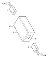
- FIG. 2 is a perspective view showing the overcurrent protection device according to the first embodiment.
- FIG. 3 is a schematic view showing the configuration of the overcurrent protection device according to the first embodiment.
- FIG. 4 is a perspective view showing the fuse connection structure according to the first embodiment.
- FIG. 5 is a perspective view of the overcurrent protection device according to the second embodiment.
- FIG. 6 is a perspective view showing a fusing member of the overcurrent protection device according to the second embodiment.
- FIG. 7 is a plan view showing the fusing member of the overcurrent protection device according to the second embodiment.
- FIG. 8 is a perspective view showing the overcurrent protection device according to the third embodiment.
- FIG. 9 is a perspective view showing a fusing member of the overcurrent protection device according to the third embodiment.
- FIG. 10 is a plan view showing the fusing member of the overcurrent protection device according to the third embodiment.
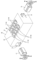
- the overcurrent protection device 10 is mounted, for example, on a vehicle Ev such as an electric vehicle or a hybrid vehicle (see FIG. 1).
- a battery module Bt is mounted on a vehicle body Bd of the vehicle Ev as a drive source.
- the battery module Bt includes a plurality of single cells (not shown) connected in series.
- the battery module Bt is connected to an indoor wire harness Wi wired in the cabin of the vehicle Ev.
- the indoor wire harness Wi penetrates the floor plate Fp and is connected to one end of the outdoor wire harness Wa wired outside the cabin.
- the other end of the outdoor wire harness Wa is introduced into the engine room accommodating the engine Eg and the like, and is connected to the indoor wire harness Wi wired in the engine room.
- the indoor wire harness Wi is connected to devices such as an inverter Iv and a motor M.
- the battery module Bt, the indoor wire harness Wi, the outdoor wire harness Wa, the indoor wire harness Wi, the inverter Iv, and the motor M are high voltage circuits 11 through which relatively high current flows. In the high voltage circuit 11, for example, a current of a voltage higher than 100 V flows.
- the detection electric wire Wb (an example of an external electric wire) which detects the state of a cell is connected to the cell of battery module Bt.
- the detection wire Wb in the present embodiment is connected to, for example, an electrode (not shown) of a unit cell to detect a voltage of the unit cell.
- the detection wire Wb is disposed outside the battery module Bt and connected to the battery control unit C.
- the battery control unit C includes a control circuit (an example of an external circuit).
- the control circuit detects the voltage of the unit cell.
- the detection wire Wb and the battery control unit C constitute a low voltage circuit 12 through which a relatively low voltage current flows. For example, a current of about 12 V flows in the low voltage circuit 12.
- the voltage of the current flowed to the low voltage circuit 12 includes 12 V and may be higher or lower than 12 V.
- a plurality of detection wires Wb are disposed in the vehicle Ev.
- transduced is distribute
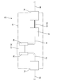
- the wire-side connector 13 is connected to the overcurrent protection device 10 via the device-side connector 14.
- two device side connectors 14 are disposed.
- the overcurrent protection device 10 is connected in series with the control circuit of the battery control unit C via the detection wire Wb.
- the detection wire Wb is normally connected to the low voltage circuit 12 through which a relatively low voltage (for example, about 12 V) flows.
- the overcurrent protection device 10 includes a case 15 and a melting member 16 disposed in the case 15.
- Case 15 is made of insulating synthetic resin.
- An apparatus-side connector 14 in which the wire-side connector 13 is fitted is opened on the outer surface of the case 15 to the outside.
- the case 15 is provided with a fusing member 16 in which a fuse 17 and an easily meltable electric wire 18 are connected in series. At least the easily meltable electric wire 18 is accommodated in the case 15.
- the fuse 17 is a fuse 17 for a vehicle mounted on a vehicle Ev such as a car.
- the fuse 17 is detachably mounted in a fuse mounting portion 22 opened in the upper surface of the case 15.
- the other terminal 23 of the fuse 17 is also connected to the fuse terminal 20.
- the internal wire 19 connected to the other terminal 23 of the fuse 17 is introduced into the interior of the internal connector 24.
- a fusible wire 18 is disposed between the internal connector 24 and the device-side connector 14 located on the right side of FIG. 3.
- the fusible wire 18 is made of a conductor having a melting point lower than that of copper, and the fusing current value is set larger than that of the fuse 17.
- metals such as lead, tin, zinc, bismuth, indium, cadmium and the like, or alloys containing one or more of these metals can be used.
- any electric wire such as a single-core wire, a stranded wire, a bare electric wire, an enameled wire, etc. can be used appropriately as needed.
- An enameled wire is used in the present embodiment.
- the operation and effects of the present embodiment will be described.
- the high voltage circuit 11 and the detection wire Wb may be short-circuited.
- a current of a voltage exceeding 100 V may flow to the battery control unit C that constitutes the low voltage circuit 12 via the detection wire Wb. In this case, it is necessary to protect the battery control unit C.
- the fusing member 16 connected in series to the battery control unit C includes the fuse 17 and the easily fusible wire 18 connected in series to the fuse 17.
- the fuse 17 having a relatively small blowing current value is melted. This suppresses the flow of an overcurrent in the battery control unit C.
- the fuse 17 and the easily fusible wire 18 are fused. Even when the fuse 17 is melted, an arc discharge occurs, so that current continues to flow through the fuse 17. Also, even when the fusible wire 18 is melted, an arc is generated between the ends of the fusible wire 18 that has been melted. However, when the end of the easily meltable electric wire 18 is melted by the heat of the arc, the distance between the ends of the easy meltable electric wire 18 is expanded. Then, the arc is extinguished and the current is cut off. As described above, by using the easily fusible wire 18, the high voltage fuse 17 may not be used even when an overcurrent of a relatively high voltage flows. As a result, the manufacturing cost of the overcurrent protection device 10 can be reduced.
- the easily meltable electric wire 18 is accommodated inside the case 15. As a result, it is possible to protect the components disposed around the overcurrent protection device 10 from the arc generated when the easily meltable electric wire 18 is melted down and the spray that the easy meltable electric wire 18 is melted and scattered.
- the wire-side connector 13 is disposed at the end of the external wire connected to the battery control unit C, and the case 15 is electrically connected to the fusing member 16
- An apparatus-side connector 14 that can be fitted to the wire-side connector 13 is provided.
- the external circuit and the overcurrent protection device 10 can be easily electrically connected to each other by fitting the wire-side connector 13 and the device-side connector 14.
- the fuse 17 can be used as the fuse 17 for a vehicle. Thereby, the manufacturing cost of the overcurrent protection device 10 can be reduced.
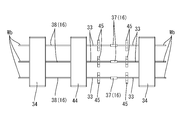
- Embodiment 2 of the present invention will be described with reference to FIGS. 5 to 7.
- two device side connectors 34 are formed in the case 35.
- FIGS. 6 and 7. The configuration in the case 35 is shown in FIGS. 6 and 7. Three easily meltable electric wires 38 are connected to the device-side connector 34 located on the left side in FIG. 7. These easily meltable wires 38 are respectively connected to the three fuses 37 via the internal connector 44.
- a pair of metal rod-like terminals 33 are projected.
- the pair of terminals 33 is supported by the support member 45.
- One of the terminals 33 is connected to the internal connector 44, and the other is connected to the device-side connector 34 located on the right side in FIG.
- the manufacturing cost of the overcurrent protection device 30 can be further reduced.
- FIG. 9 and 10 show the structure in the case 55.
- FIG. A plurality of easily meltable electric wires 58 are connected to the device-side connector 54 positioned on the left side in FIG.
- the easily meltable wires 58 are connected to the internal connector 64.
- the internal connector 64 is attached to the printed circuit board 65.
- a conductive path (not shown) is formed on the printed circuit board 65 by the printed wiring technology.
- the fusible wire 58 is connected to the conductive path of the printed circuit board 65 by a known method such as soldering.
- a plurality of fuses 57 are mounted on the printed circuit board 65.
- the fuse 57 according to the present embodiment uses a fuse 57 for a substrate.
- Each fuse 57 is connected to the conductive path of the printed circuit board 65 by a known method such as soldering.
- soldering a known method such as soldering.
- the easily meltable wires 58 are connected in series to the fuses 57.
- the device-side connector 54 located on the right side in FIG. 10 is mounted on the printed circuit board 65 and connected to the conductive path of the printed circuit board 65 by a known method such as soldering.
- the over current protection device can be miniaturized.
- overcurrent protection devices 10, 30, and 50 are configured to be mounted on the vehicle Ev, the present invention is not limited thereto, and may be appropriately mounted on any device such as a computer or communication device. it can.
- the fusing member 16 is disposed in the case 15.
- the present invention is not limited to this, and the case 15 may be omitted.
- the internal connector 24 is interposed between the fuse 17 and the easily fusible wire 18, but the present invention is not limited to this.
- the easily fusible wire 18 is connected to the fuse terminal 20. Therefore, the internal connector 24 may be omitted.
- Overcurrent protection device 11 High voltage circuit 12: Low voltage circuit 13: Wire side connector 14, 34, 54: Device side connector 15, 35 Case 17, 37, 57 ... fuse 18, 38, 58 ... easily melted wire 65 ... printed circuit board Bt ... battery module (high voltage circuit) C: Battery control unit (external circuit, low voltage circuit) Ev: Vehicle Iv: Inverter (high voltage circuit) M: Motor (high voltage circuit) Wa ... outdoor wire harness (high voltage circuit) Wb ... detection wire (external wire, low voltage circuit) Wi ... Indoor wire harness (high voltage circuit)
Landscapes
- Engineering & Computer Science (AREA)
- Mechanical Engineering (AREA)
- Fuses (AREA)
- Emergency Protection Circuit Devices (AREA)
Priority Applications (3)
| Application Number | Priority Date | Filing Date | Title |
|---|---|---|---|
| CN201280069779.1A CN104115252B (zh) | 2012-02-15 | 2012-12-26 | 过电流保护装置 |
| US14/377,285 US9490094B2 (en) | 2012-02-15 | 2012-12-26 | Overcurrent protection apparatus |
| EP12868758.9A EP2801996A4 (en) | 2012-02-15 | 2012-12-26 | OVERCURRENT PROTECTION DEVICE |
Applications Claiming Priority (2)
| Application Number | Priority Date | Filing Date | Title |
|---|---|---|---|
| JP2012030106A JP5626234B2 (ja) | 2012-02-15 | 2012-02-15 | 過電流保護装置 |
| JP2012-030106 | 2012-02-15 |
Publications (1)
| Publication Number | Publication Date |
|---|---|
| WO2013121685A1 true WO2013121685A1 (ja) | 2013-08-22 |
Family
ID=48983827
Family Applications (1)
| Application Number | Title | Priority Date | Filing Date |
|---|---|---|---|
| PCT/JP2012/083604 WO2013121685A1 (ja) | 2012-02-15 | 2012-12-26 | 過電流保護装置 |
Country Status (5)
| Country | Link |
|---|---|
| US (1) | US9490094B2 (zh) |
| EP (1) | EP2801996A4 (zh) |
| JP (1) | JP5626234B2 (zh) |
| CN (1) | CN104115252B (zh) |
| WO (1) | WO2013121685A1 (zh) |
Families Citing this family (7)
| Publication number | Priority date | Publication date | Assignee | Title |
|---|---|---|---|---|
| JP5704406B2 (ja) * | 2011-11-30 | 2015-04-22 | 株式会社オートネットワーク技術研究所 | コネクタ及びワイヤーハーネス |
| JP2018014301A (ja) * | 2016-07-22 | 2018-01-25 | 株式会社豊田自動織機 | 電池モジュール |
| JP7056130B2 (ja) * | 2017-12-15 | 2022-04-19 | トヨタ自動車株式会社 | 衝突検知装置 |
| JP6947139B2 (ja) * | 2018-08-29 | 2021-10-13 | 株式会社オートネットワーク技術研究所 | 過電流遮断ユニット |
| JP7226075B2 (ja) | 2019-05-10 | 2023-02-21 | 住友ゴム工業株式会社 | タイヤの厚さ測定装置 |
| FR3103960B1 (fr) * | 2019-12-02 | 2021-11-19 | Psa Automobiles Sa | Vehicule automobile équipé d’un boîtier de fusibles disposé dans un compartiment arrière |
| JP2021136700A (ja) * | 2020-02-21 | 2021-09-13 | 住友電装株式会社 | 電気接続箱 |
Citations (4)
| Publication number | Priority date | Publication date | Assignee | Title |
|---|---|---|---|---|
| JPS5650044U (zh) * | 1979-09-26 | 1981-05-02 | ||
| JPH08106956A (ja) * | 1994-10-03 | 1996-04-23 | Chubu Electric Power Co Inc | 引込用ヒューズ内蔵コネクター |
| JPH0917323A (ja) | 1995-06-26 | 1997-01-17 | Taiheiyo Seiko Kk | 差し込み式ヒューズ |
| JP2005297860A (ja) * | 2004-04-14 | 2005-10-27 | Toyota Motor Corp | 車両用電源装置 |
Family Cites Families (12)
| Publication number | Priority date | Publication date | Assignee | Title |
|---|---|---|---|---|
| US4224592A (en) * | 1978-04-03 | 1980-09-23 | Mcgraw-Edison Company | Miniature plug-in fuse assembly and method of manufacture |
| JPS5650044A (en) * | 1979-09-29 | 1981-05-07 | Murata Mfg Co Ltd | Channel type secondary electron amplifier |
| US4488137A (en) * | 1983-08-29 | 1984-12-11 | Commercial Enclosed Fuse Company | Composite fuse links employing dissimilar fusible elements in a series |
| US4652848A (en) * | 1986-06-06 | 1987-03-24 | Northern Telecom Limited | Fusible link |
| US5034974A (en) * | 1990-05-03 | 1991-07-23 | Yurosko John J | Dental X-ray patient identification marking device |
| US5329204A (en) * | 1992-03-09 | 1994-07-12 | Ricca Tom L | Attachment for automatic light switching |
| US5304974A (en) * | 1992-09-30 | 1994-04-19 | Siemens Stromberg-Carlson | Low profile thermal cut-off resistor |
| JP2000502560A (ja) | 1996-10-24 | 2000-02-29 | トーマス アンド ベッツ インターナショナル インコーポレイテッド | 電力ディストリビューション・センター |
| US5923239A (en) * | 1997-12-02 | 1999-07-13 | Littelfuse, Inc. | Printed circuit board assembly having an integrated fusible link |
| DE19809186A1 (de) * | 1998-03-04 | 1999-09-09 | Efen Elektrotech Fab | Mehrbereichssicherung mit metallischem Schirm |
| US7710236B2 (en) * | 2006-08-01 | 2010-05-04 | Delphi Technologies, Inc. | Fuse systems with serviceable connections |
| US7433794B1 (en) * | 2007-07-18 | 2008-10-07 | Tesla Motors, Inc. | Mitigation of propagation of thermal runaway in a multi-cell battery pack |
-
2012
- 2012-02-15 JP JP2012030106A patent/JP5626234B2/ja not_active Expired - Fee Related
- 2012-12-26 WO PCT/JP2012/083604 patent/WO2013121685A1/ja active Application Filing
- 2012-12-26 US US14/377,285 patent/US9490094B2/en active Active
- 2012-12-26 CN CN201280069779.1A patent/CN104115252B/zh not_active Expired - Fee Related
- 2012-12-26 EP EP12868758.9A patent/EP2801996A4/en not_active Withdrawn
Patent Citations (4)
| Publication number | Priority date | Publication date | Assignee | Title |
|---|---|---|---|---|
| JPS5650044U (zh) * | 1979-09-26 | 1981-05-02 | ||
| JPH08106956A (ja) * | 1994-10-03 | 1996-04-23 | Chubu Electric Power Co Inc | 引込用ヒューズ内蔵コネクター |
| JPH0917323A (ja) | 1995-06-26 | 1997-01-17 | Taiheiyo Seiko Kk | 差し込み式ヒューズ |
| JP2005297860A (ja) * | 2004-04-14 | 2005-10-27 | Toyota Motor Corp | 車両用電源装置 |
Non-Patent Citations (1)
| Title |
|---|
| See also references of EP2801996A4 |
Also Published As
| Publication number | Publication date |
|---|---|
| US9490094B2 (en) | 2016-11-08 |
| JP5626234B2 (ja) | 2014-11-19 |
| CN104115252B (zh) | 2017-07-04 |
| JP2013168263A (ja) | 2013-08-29 |
| CN104115252A (zh) | 2014-10-22 |
| US20150022931A1 (en) | 2015-01-22 |
| EP2801996A1 (en) | 2014-11-12 |
| EP2801996A4 (en) | 2016-03-02 |
Similar Documents
| Publication | Publication Date | Title |
|---|---|---|
| WO2013121685A1 (ja) | 過電流保護装置 | |
| US10468661B2 (en) | Power battery assembly | |
| US9953793B2 (en) | Short-circuit element and a circuit using the same | |
| JP6524051B2 (ja) | 導体の接続構造および導電モジュール | |
| JPH11250790A (ja) | 強制溶断ヒューズおよび電流遮断装置 | |
| CN110226246A (zh) | 用于电池系统的汇流条组件 | |
| JP5952674B2 (ja) | 保護素子及びバッテリパック | |
| JP2013017373A (ja) | 環境に優しい車両のバッテリセル保護装置 | |
| JP2013168263A5 (zh) | ||
| US10957891B2 (en) | Wiring module | |
| JP2002369337A (ja) | 保護機能付きの電気接続箱 | |
| JP2000324674A (ja) | ワイヤーハーネス装置 | |
| TW201524064A (zh) | 電池電路、保護電路 | |
| US7973324B2 (en) | Lamp type light emitting device for safety fuse | |
| WO2011096375A1 (ja) | 過電流遮断素子付き端子 | |
| US10153124B2 (en) | Multi-load fuse block | |
| JP2012129124A (ja) | 回路保護素子およびそれを用いた電池パック装置 | |
| JP7081492B2 (ja) | 接続部材、移動体および電力供給システム | |
| KR101529829B1 (ko) | 복합보호소자 | |
| CA2379009A1 (en) | Trace fuse for a battery termination | |
| JP4593518B2 (ja) | ヒューズ付半導体装置 | |
| JP7309323B2 (ja) | セメント抵抗器 | |
| JP2010112764A (ja) | 電線過電流印加実験装置 | |
| KR101381427B1 (ko) | 전류 스위치 개별 퓨즈 구조 | |
| JPH097496A (ja) | 自動車用ワイヤハーネスの回路保護装置 |
Legal Events
| Date | Code | Title | Description |
|---|---|---|---|
| 121 | Ep: the epo has been informed by wipo that ep was designated in this application |
Ref document number: 12868758 Country of ref document: EP Kind code of ref document: A1 |
|
| WWE | Wipo information: entry into national phase |
Ref document number: 2012868758 Country of ref document: EP |
|
| WWE | Wipo information: entry into national phase |
Ref document number: 14377285 Country of ref document: US |
|
| NENP | Non-entry into the national phase |
Ref country code: DE |