WO2013115287A1 - 色素増感太陽電池のエージング方法 - Google Patents
色素増感太陽電池のエージング方法 Download PDFInfo
- Publication number
- WO2013115287A1 WO2013115287A1 PCT/JP2013/052123 JP2013052123W WO2013115287A1 WO 2013115287 A1 WO2013115287 A1 WO 2013115287A1 JP 2013052123 W JP2013052123 W JP 2013052123W WO 2013115287 A1 WO2013115287 A1 WO 2013115287A1
- Authority
- WO
- WIPO (PCT)
- Prior art keywords
- dye
- sensitized solar
- negative electrode
- solar cell
- aging
- Prior art date
- Legal status (The legal status is an assumption and is not a legal conclusion. Google has not performed a legal analysis and makes no representation as to the accuracy of the status listed.)
- Ceased
Links
Images

Classifications
-
- H—ELECTRICITY
- H01—ELECTRIC ELEMENTS
- H01G—CAPACITORS; CAPACITORS, RECTIFIERS, DETECTORS, SWITCHING DEVICES, LIGHT-SENSITIVE OR TEMPERATURE-SENSITIVE DEVICES OF THE ELECTROLYTIC TYPE
- H01G9/00—Electrolytic capacitors, rectifiers, detectors, switching devices, light-sensitive or temperature-sensitive devices; Processes of their manufacture
- H01G9/20—Light-sensitive devices
- H01G9/2027—Light-sensitive devices comprising an oxide semiconductor electrode
- H01G9/2031—Light-sensitive devices comprising an oxide semiconductor electrode comprising titanium oxide, e.g. TiO2
-
- H—ELECTRICITY
- H01—ELECTRIC ELEMENTS
- H01G—CAPACITORS; CAPACITORS, RECTIFIERS, DETECTORS, SWITCHING DEVICES, LIGHT-SENSITIVE OR TEMPERATURE-SENSITIVE DEVICES OF THE ELECTROLYTIC TYPE
- H01G9/00—Electrolytic capacitors, rectifiers, detectors, switching devices, light-sensitive or temperature-sensitive devices; Processes of their manufacture
- H01G9/20—Light-sensitive devices
- H01G9/2059—Light-sensitive devices comprising an organic dye as the active light absorbing material, e.g. adsorbed on an electrode or dissolved in solution
-
- Y—GENERAL TAGGING OF NEW TECHNOLOGICAL DEVELOPMENTS; GENERAL TAGGING OF CROSS-SECTIONAL TECHNOLOGIES SPANNING OVER SEVERAL SECTIONS OF THE IPC; TECHNICAL SUBJECTS COVERED BY FORMER USPC CROSS-REFERENCE ART COLLECTIONS [XRACs] AND DIGESTS
- Y02—TECHNOLOGIES OR APPLICATIONS FOR MITIGATION OR ADAPTATION AGAINST CLIMATE CHANGE
- Y02E—REDUCTION OF GREENHOUSE GAS [GHG] EMISSIONS, RELATED TO ENERGY GENERATION, TRANSMISSION OR DISTRIBUTION
- Y02E10/00—Energy generation through renewable energy sources
- Y02E10/50—Photovoltaic [PV] energy
- Y02E10/542—Dye sensitized solar cells
Definitions
- the present invention relates to an aging method for a dye-sensitized solar cell.
- a general method for producing a dye-sensitized solar cell as a photoelectric conversion element is, for example, as follows. First, a transparent conductive electrode film is formed on a transparent substrate such as a glass plate, and a film made of a metal oxide such as titanium oxide is formed on the electrode film. Then, a negative electrode is produced by forming a power generation layer by bringing a solution containing a photosensitizing dye such as a ruthenium complex into contact with the surface of the metal oxide film to adsorb the dye. Separately, a catalyst layer such as a platinum layer is formed on a conductive substrate to produce a positive electrode.
- a dye-sensitized solar cell can be manufactured by inject
- pouring electrolyte solutions such as an iodine solution
- a highly viscous electrolyte that is, a highly viscous gelled electrolyte
- a metal oxide film and a highly viscous electrolyte are interposed between the positive electrode and the negative electrode
- a dye-sensitized solar cell can be manufactured by bonding the parts by heating or the like.
- a part of the photosensitizing dye once adsorbed on the metal oxide film is dispersed in the electrolyte by dropping off from the metal oxide film.
- a photosensitizing dye that is floating without being adsorbed to the oxide film Due to this, characteristics of the obtained dye-sensitized solar cell (for example, conversion efficiency and life of the obtained battery) may be deteriorated. Therefore, for the purpose of improving battery characteristics, the dye-sensitized solar cell thus obtained is placed in a cool and dark place in order to strongly adsorb the dye to the metal oxide film and to familiarize the metal oxide film and the dye. Storage for a predetermined time, that is, aging is performed.
- JP2001-093588A even when the dye-sensitized solar cell in the state where the periphery is sealed is heated, the electrolyte in the battery is still discharged as vapor. Battery performance will be degraded. In other words, using the method described in JP2001-093588A can shorten the aging time, but still has a problem that the deterioration of the battery characteristics after aging cannot be suppressed.
- the present invention has been made in view of the above-described problems of the known technology, and an object of the present invention is to provide a dye-sensitized solar cell aging method capable of greatly shortening the aging time while suppressing deterioration of battery characteristics.
- the gist of the present invention is as follows.
- a method for aging a dye-sensitized solar cell comprising the following steps (I) and (II) in this order: (I) having a negative electrode in which a metal oxide film is formed on a conductive substrate, and a photosensitizing dye is adsorbed on the metal oxide film, and a positive electrode arranged corresponding to the negative electrode; A step of producing a dye-sensitized solar cell in which an electrolyte is interposed between the negative electrode and the positive electrode.
- step (II) For the dye-sensitized solar cell obtained in step (I), an electrical load is connected between the negative electrode and the positive electrode while irradiating light, or the negative electrode and A step of applying a voltage between the positive electrodes.
- step (I) at least one selected from ruthenium complexes, coumarins, merocyanines and indolines is used as a photosensitizing dye, and the dye sensitization according to any one of (1) to (3) Solar cell aging method.
- the aging time can be greatly shortened, so that the electrolyte solution in the battery is strong against the metal oxide film without escaping as a vapor.
- the dye can be adsorbed to the battery, and as a result, deterioration of battery characteristics can be suppressed. Therefore, a dye-sensitized solar cell having a stable output can be obtained with high productivity.
- the aging method of the dye-sensitized solar cell of this invention it is the schematic which shows the process in which the photosensitizing dye of the state suspended in the electrolyte is made to adsorb
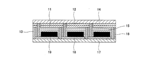
- the Example of this invention it is a schematic sectional drawing of the dye-sensitized solar cell after aging with the aging method of this invention.
- the aging method of a dye-sensitized solar cell of the present invention is characterized by having the following steps (I) and (II) in this order.
- (I) having a negative electrode in which a metal oxide film is formed on a conductive substrate, and a photosensitizing dye is adsorbed on the metal oxide film, and a positive electrode arranged corresponding to the negative electrode;
- an electrical load is connected between the negative electrode and the positive electrode while irradiating light, or the negative electrode and A step of applying a voltage between the positive electrodes.
- the negative electrode has a structure in which a metal oxide film is formed on a conductive substrate and a photosensitizing dye is adsorbed on the metal oxide film.
- the conductive substrate a substrate in which a transparent conductive film is formed on a transparent substrate or a substrate made of a conductive material such as metal is used.
- a substrate in which a transparent conductive film is formed on a transparent substrate or a substrate made of a conductive material such as metal is used.
- a transparent conductive film is formed on a transparent substrate or a substrate made of a conductive material such as metal is used.
- a substrate made of a conductive material such as metal
- Examples of the transparent substrate constituting the conductive substrate include a synthetic resin plate; a glass plate; a film made of a thermoplastic resin.
- Examples of the thermoplastic resin for forming this film include polyester resins such as polyethylene naphthalate (PEN) and polyethylene terephthalate (PET), polycarbonate resins, and polyolefins.
- PEN polyethylene naphthalate
- PET polyethylene terephthalate
- a film made of a thermoplastic resin is preferable from the viewpoint of lightness and safety (that is, hardly damaged).
- Examples of the conductive film formed on the transparent substrate include tin-added indium oxide (ITO), fluorine-added tin oxide (FTO), tin oxide (SnO 2 ), indium zinc oxide (IZO), and zinc oxide (ZnO). And a thin film containing a conductive metal oxide.
- ITO indium oxide
- FTO fluorine-added tin oxide
- SnO 2 tin oxide
- IZO indium zinc oxide
- ZnO zinc oxide
- a thin film containing a conductive metal oxide since the strength as a material is high, the applied voltage at the time of aging can be increased. As a result, in the dye-sensitized solar cell after aging, the photosensitizing dye and the metal oxide film described later From the viewpoint of making adsorption stronger, it is preferable to use FTO.
- a known method can be appropriately selected as a method for forming the conductive film. However, there is no particular limitation.
- Examples of the method for forming the metal oxide film include the following methods. That is, first, a mixed solution is prepared by stirring and mixing metal oxide fine particles, an organic solvent, water, and the like. Subsequently, after apply
- the metal oxide fine particles include fine particles of titanium oxide (TiO 2 ), tin oxide (SnO 2 ), tungsten oxide (WO 3 ), zinc oxide (ZnO), niobium oxide (Nb 2 O 5 ), and the like. It is done. However, there is no particular limitation.
- the size (particle size) of the fine particles is usually preferably about 5 to 100 nm. However, the size of the fine particles is not particularly limited.
- organic solvent examples include alcohol, acetone, hexane and the like.
- the negative electrode has a structure in which a photosensitizing dye is adsorbed on the surface of such a metal oxide film.
- a photosensitizing dye is adsorbed on the surface of such a metal oxide film.
- the substrate on which the metal oxide film is formed is immersed in a solution containing the dye (dye solution) for a predetermined time. The method etc. are mentioned.
- the dye solution is a solution obtained by dissolving a photosensitizing dye in an organic solvent.
- the organic solvent for dissolving the dye include alcohols such as ethanol and acetonitrile.
- titanium oxide is used as a metal oxide for forming a metal oxide film
- titanium (IV) isopropoxide as a photocatalyst precursor solution is used for the purpose of strengthening the bond of titanium oxide.
- a solution obtained by dissolving (TTIP) in propanol may be mixed with the dye solution.
- the photosensitizing dye examples include a ruthenium complex having a ligand containing a pyridine structure or a terpyridine structure; an iron complex having a ligand containing a pyridine structure or a terpyridine structure; a porphyrin-based or phthalocyanine-based metal complex; Organic dyes such as eosin, rhodamine, merocyanine, coumarin, and indoline are listed. However, there is no particular limitation. Of these, a ruthenium complex is preferably used from the viewpoint of versatility, and an organic dye is preferably used from the viewpoint of solubility in an organic solvent.
- the content of the photosensitizing dye in the dye solution is not particularly limited, but is preferably 0.2 to 1.0 mM, and more preferably 0.3 to 0.6 mM.
- the content of the photosensitizing dye is less than 0.2 mM, a sufficient amount of the dye is not adsorbed to the metal oxide film, which may be inferior in battery characteristics.
- the dye may remain undissolved in the dye solution, or adsorption unevenness may occur on the metal oxide film.
- the amount of dye carried on the metal oxide film is increased, but bonding between the dyes also occurs, so that the flow of electrons from the dye to the metal oxide film is hindered. There may be a problem that the oxide film is not firmly adsorbed.
- the positive electrode is described below.
- the positive electrode examples include those in which a transparent conductive film is formed on a transparent substrate, and metal sheets such as aluminum, copper, and tin.
- a gel-like high-viscosity electrolytic solution may be held on a metal mesh electrode (for example, aluminum, copper, tin, or the like) or carbon and used as a positive electrode.
- a conductive adhesive layer on one side of the transparent substrate so as to cover the substrate, and transferring the separately formed brush-like carbon nanotube group to the substrate via the adhesive layer, You may comprise a positive electrode.
- a catalyst layer such as a platinum layer may be formed.
- the technique for forming the platinum layer is a technique such as sputtering or immersing the positive electrode in a platinum nanocolloid solution or the like. However, there is no particular limitation.
- the ITO may be patterned using a laser or the like.
- a current collector having a thickness of about several ⁇ m is preferably formed on the substrate constituting the positive electrode and the negative electrode by applying a silver paste or the like using a screen printer or the like.
- a dye-sensitized solar cell having the negative electrode as described above and a positive electrode arranged corresponding to the negative electrode and an electrolyte interposed between the negative electrode and the positive electrode is manufactured.
- a method for producing the dye-sensitized solar cell for example, a method in which the negative electrode and the positive electrode as described above are arranged to face each other, and an electrolyte is interposed between the negative electrode and the positive electrode by an appropriate means, etc. Can be mentioned.
- the method for producing the dye-sensitized solar cell is not particularly limited.
- Examples of the electrolyte interposed between the negative electrode and the positive electrode include an electrolytic solution or a highly viscous electrolytic solution (a highly viscous gelled electrolytic solution).
- Examples of the electrolytic solution include iodine-based electrolytic solution.
- an electrolytic solution in which an electrolyte component such as iodine, iodide ion, or tertiary butyl pyridine is dissolved in an organic solvent such as ethylene carbonate or methoxyacetonitrile can be used.
- an electrolytic solution using a cobalt complex or the like instead of the iodine-based electrolyte component may be used.
- Examples of the highly viscous electrolyte include dimethylpropylimidazolium iodide (DMPImI), metal iodide (lithium iodide, sodium iodide, potassium iodide, cesium iodide, calcium iodide), tetraalkylammonium iodide, and the like.
- DMPImI dimethylpropylimidazolium iodide
- metal iodide lithium iodide, sodium iodide, potassium iodide, cesium iodide, calcium iodide
- tetraalkylammonium iodide and the like.
- a combination of iodide and iodine such as iodine salt of a quaternary ammonium compound, metal bromide (lithium bromide, sodium bromide, potassium bromide, cesium bromide, calcium bromide), tetraalkylammonium bromide 4
- iodide and iodine such as iodine salt of a quaternary ammonium compound, metal bromide (lithium bromide, sodium bromide, potassium bromide, cesium bromide, calcium bromide), tetraalkylammonium bromide 4
- bromide such as bromine salt of a quaternary ammonium compound and bromine can be appropriately used.
- the negative electrode and the positive electrode can be sealed by, for example, the following method so that the electrolytic solution does not leak. That is, the negative electrode and the positive electrode are arranged so that they face each other, and the space between the edges of both electrodes is sealed with a heat-sealing film or a sealing material to form a space. And a hole is opened beforehand in a negative electrode and / or a positive electrode, and electrolyte solution is inject
- the negative electrode and the positive electrode can be sealed using a method such as heat bonding.
- the heat bonding may be bonding using a mold, or is performed by irradiating with an energy beam such as plasma, microwave, visible light (having a wavelength of 600 nm or more), and infrared rays. There may be.
- sealing of the negative electrode and the positive electrode is not limited to these methods.
- the dye-sensitized solar cell includes, for example, a negative electrode conductive film, a metal oxide film, an electrolyte layer, and a positive electrode conductive film between a rectangular negative electrode transparent substrate and a rectangular positive electrode transparent substrate. Is formed.
- the connection between the positive electrode and the negative electrode may be in series or in parallel. In either case, the electrolyte layer and the metal oxide film are separated from each other by a sealing material.
- the conductive film for negative electrode, the conductive film for positive electrode, and the connection electrode for connecting the positive electrode and the negative electrode are formed with a gap between adjacent ones. It may be connected by a conductor. On the other hand, in the case of parallel connection, it may be shaped such that there is no gap between the adjacent negative electrode conductive film and positive electrode conductive film.
- step (II) an electrical load is connected between the negative electrode and the positive electrode while irradiating light to the dye-sensitized solar cell obtained in the step (I), or This is a step of applying a voltage between the negative electrode and the positive electrode while irradiating light.
- the following describes applying a voltage between the negative electrode and the positive electrode while irradiating light.
- step (II) a remarkable effect that the aging time can be greatly shortened can be obtained by performing the process of connecting a load or applying a voltage as in step (II).
- the obtained dye-sensitized solar cell is connected to a load or applied with a voltage while irradiating light, whereby the dye dispersed in the electrolyte is attracted again to the metal oxide film. Further, it is possible to promote a strong bond between the dye and the metal oxide film. As a result, the aging time, which normally requires a long time of several months, can be greatly shortened (for example, about 5 to 30 minutes) while suppressing the deterioration of the characteristics of the obtained battery. As a result, productivity can be improved. Further, the shortening of the aging time can effectively prevent the electrolytic solution inside the battery from being discharged as vapor.
- step (II) as a light source for irradiating light, for example, a xenon lamp or a metal halide lamp can be used.
- the irradiance of the light irradiated in the step (II) is preferably 0.1 to 200 mW / cm 2 , and more preferably 80 to 100 mW / cm 2 . If it is less than 0.1 mW / cm 2 , the aging time may not be sufficiently shortened. On the other hand, if it exceeds 200 mW / cm 2 , the dye may deteriorate.
- the voltage applied between the negative electrode and the positive electrode is preferably 0.1 to 10 V, depending on the distance between the electrodes and the type of dye used. If the applied voltage is less than 0.1 V, the aging time may not be shortened sufficiently. On the other hand, when the applied voltage exceeds 10 V, the resistance becomes too high, and the transparent conductive film constituting the negative electrode and the positive electrode in the dye-sensitized solar cell after aging may deteriorate.
- a resistor When connecting a resistor as an electrical load, a known one such as a light bulb or a light emitting diode may be connected in an appropriate state.
- a resistance for example, a resistance in the range of several ⁇ to several hundred ⁇ can be used, and is not particularly limited.
- the positive electrode 9 includes a conductive substrate 2 and a catalyst layer 3 made of platinum or the like.
- the negative electrode 10 includes a conductive substrate 7 and a metal oxide film 6 formed of metal oxide fine particles.
- the photosensitizing dye 5 that has fallen off from the metal oxide film 6 and floated in the electrolyte 1 emits electrons 4 due to light irradiation 8 and has a positive charge.
- the photosensitizing dye 5 having a positive charge is attracted to the metal oxide film 6 and adsorbed on the metal oxide film 6. Is done.
- the obtained dye-sensitized solar cell it can accelerate
- the aging time can be greatly shortened.
- the battery characteristic evaluation method in the examples of the present invention is as follows. That is, AM (air mass) 1.5 before and after applying light irradiation and voltage application under the conditions described later for aging on the obtained dye-sensitized solar cell (size: 100 mm ⁇ 100 mm), By irradiating light from a standard light source under a power density of 100 mW / cm 2 , current density, open voltage, fill factor, and conversion efficiency were measured. Light irradiation and voltage application for aging correspond to step (II). (Example)
- the Z-type dye-sensitized solar cell shown in FIG. 2 was produced as follows.
- a polyethylene naphthalate resin film was used as the transparent substrate 17 constituting the negative electrode.
- a conductive film 18 made of tin-added indium oxide was formed on the surface of this film. Further, a titanium oxide paste is applied on the conductive film 18, then baked at 150 ° C., and then immersed in a dye solution, whereby a metal oxide film 19 (thickness: About 6 ⁇ m).
- the negative electrode was configured as described above.
- a film made of polyethylene naphthalate resin was used for the transparent substrate 14 constituting the positive electrode.
- a conductive film 12 made of tin-added indium oxide was formed on the film surface. And the transparent layer 14 in which this electroconductive film 12 was formed was immersed in the platinum nanocolloid solution, the platinum layer 11 as a catalyst layer was formed, and the positive electrode was comprised.
- a sealing material 13 (commercially available UV curable sealing material) was applied to the end of the metal oxide film 19 of the negative electrode. Further, the electrolyte solution 15 was supplied toward the metal oxide film 19 under reduced pressure, and then bonded to the positive electrode. And the sealing material was hardened by irradiating UV, and the both ends of the negative electrode and the positive electrode were sealed. Furthermore, the dye-sensitized solar cell was obtained by setting the connection electrode 16 for connecting the adjacent negative electrode and positive electrode.
- the electrolytic solution 15 As the electrolytic solution 15, the following was used. In other words, acetonitrile added with 0.05 M iodine, 0.10 M lithium iodide, 0.06 mM DMPI, and 0.50 M 4-tert-butylpyridine was used.
- the measurement results of the battery characteristics of the dye-sensitized solar cell before aging are as follows: the current density is 5.1 mA / cm 2 , the open circuit voltage is 0.55 V, and the fill factor is 0.40. The conversion efficiency was 1.12%. Furthermore, in the above-described embodiment, the measurement results of the battery characteristics of the battery after aging are as follows. The current density is 8.45 mA / cm 2 , the open circuit voltage is 0.68 V, the fill factor is 0.60, and the conversion efficiency is 3.43. %Met.
- the firing temperature of the metal oxide film was set to a relatively low temperature of 150 ° C.
- fluorine-containing tin oxide stronger than tin-doped indium oxide can be used as the conductive film.
- the voltage applied to can be increased.
- the adsorption of the dye can be more effectively promoted, and the aging time can be effectively shortened while suppressing the deterioration of the battery characteristics.
Landscapes
- Engineering & Computer Science (AREA)
- Power Engineering (AREA)
- Microelectronics & Electronic Packaging (AREA)
- Hybrid Cells (AREA)
- Photovoltaic Devices (AREA)
Description
本発明は、色素増感太陽電池のエージング方法に関する。
光電変換素子としての色素増感太陽電池の一般的な製造方法は、例えば、以下のようなものである。まず、ガラス板などの透明基板上に透明な導電性電膜を形成し、この電膜上に酸化チタンなどの金属酸化物からなる膜を形成する。そして、この金属酸化物膜の表面にルテニウム錯体などの光増感色素を含有する溶液を接触させて色素を吸着させることで発電層を形成することにより、負極を作製する。別途、導電性基板上に白金層などの触媒層を形成して正極を作製する。
次いで、上記のような正極および負極を対向させて配置し、これらの周囲を封止材によって封止させて空間を形成する。その後、この空間に、予め設けておいた孔や隙間からヨウ素液などの電解液を注入することで、色素増感太陽電池を製造することができる。一方、電解質として高粘性電解液(つまり、粘性の高い、ゲル状の電解液)を用いる場合には、正極と負極との間に金属酸化物膜および高粘性電解液を介在させ、これらの周縁部を加熱などにより接着することで、色素増感太陽電池を製造することができる。
一般的に、色素増感太陽電池においては、いったんは金属酸化物膜に吸着された光増感色素の一部が、金属酸化物膜から脱落することにより電解質中に分散してしまうため、金属酸化物膜に対して吸着していない状態で浮遊している光増感色素が存在している。これに起因して、得られる色素増感太陽電池の特性(例えば、得られる電池の変換効率や寿命など)が低下してしまう場合がある。そこで、電池特性を向上させることを目的として、金属酸化物膜に対して強固に色素を吸着させ、かつ金属酸化物膜および色素をなじませるために、得られた色素増感太陽電池を冷暗所にて所定時間保管すること、すなわちエージングが行われている。
通常、エージングを行うには、数ヶ月程度という長い期間が必要とされる。そのため、得られた電池を保管するための費用や場所が必要となるという問題や、エージングの最中に電池内部の電解液が蒸気となって抜けてしまうことにより、かえって電池特性が低下するという問題がある。
このような問題を解決するため、得られた太陽電池を加温しながらエージングを行うことにより、エージング時間(エージングのための色素増感太陽電池の保管期間)を短縮しようとすることが知られている(例えば、JP2001-093588A)。
しかしながら、JP2001-093588Aに記載されたように、その周囲が封止された状態の色素増感太陽電池を加温した場合であっても、やはり電池内部の電解液が蒸気となって抜けてしまい、電池性能が低下してしまう。つまり、JP2001-093588Aに記載された手法を用いると、エージング時間を短縮することはできるが、依然として、エージング後の電池特性の低下を抑制することができないという問題がある。
本発明は、上記のような公知技術の問題に鑑み、電池特性の低下を抑制しつつ、エージング時間を大幅に短縮しうる色素増感太陽電池のエージング方法を提供することを目的とする。
すなわち本発明は、以下を要旨とする。
(1)以下の工程(I)および(II)をこの順に有することを特徴とする色素増感太陽電池のエージング方法。
(I)導電性基板上に金属酸化物膜が形成され、かつこの金属酸化物膜に光増感色素が吸着されている負極と、この負極に対応して配置された正極とを有するとともに、これらの負極と正極との間に電解質が介在されている色素増感太陽電池を作製する工程。
(II)工程(I)で得られた色素増感太陽電池に対して、光の照射を行いながら負極および正極の間に電気的な負荷を接続するか、あるいは光の照射を行いながら負極および正極の間に電圧を印加する工程。
(2)工程(II)において、負極および正極の間に印加させる電圧を0.1~10Vとすることを特徴とする(1)の色素増感太陽電池のエージング方法。
(3)工程(II)において、照射する光の放射照度を0.1~200mW/cm2とすることを特徴とする(1)または(2)の色素増感太陽電池のエージング方法。
(4)工程(I)において、光増感色素としてルテニウム錯体、クマリン、メロシアニンおよびインドリンから選択される1種以上を用いることを特徴とする(1)~(3)のいずれかの色素増感太陽電池のエージング方法。
(1)以下の工程(I)および(II)をこの順に有することを特徴とする色素増感太陽電池のエージング方法。
(I)導電性基板上に金属酸化物膜が形成され、かつこの金属酸化物膜に光増感色素が吸着されている負極と、この負極に対応して配置された正極とを有するとともに、これらの負極と正極との間に電解質が介在されている色素増感太陽電池を作製する工程。
(II)工程(I)で得られた色素増感太陽電池に対して、光の照射を行いながら負極および正極の間に電気的な負荷を接続するか、あるいは光の照射を行いながら負極および正極の間に電圧を印加する工程。
(2)工程(II)において、負極および正極の間に印加させる電圧を0.1~10Vとすることを特徴とする(1)の色素増感太陽電池のエージング方法。
(3)工程(II)において、照射する光の放射照度を0.1~200mW/cm2とすることを特徴とする(1)または(2)の色素増感太陽電池のエージング方法。
(4)工程(I)において、光増感色素としてルテニウム錯体、クマリン、メロシアニンおよびインドリンから選択される1種以上を用いることを特徴とする(1)~(3)のいずれかの色素増感太陽電池のエージング方法。
本発明の色素増感太陽電池のエージング方法によれば、エージング時間を大幅に短縮することができるため、電池内部の電解液が蒸気となって抜けてしまうことなく金属酸化物膜に対して強固に色素を吸着させることができ、その結果、電池特性の低下を抑制することができる。そのため、安定した出力を有する色素増感太陽電池を生産性よく得ることができる。
以下、本発明を詳細に説明する。
本発明の色素増感太陽電池のエージング方法は、以下の工程(I)および(II)をこの順に有することを特徴とする。
(I)導電性基板上に金属酸化物膜が形成され、かつこの金属酸化物膜に光増感色素が吸着されている負極と、この負極に対応して配置された正極とを有するとともに、これらの負極と正極との間に電解質が介在されている色素増感太陽電池を作製する工程。
(II)工程(I)で得られた色素増感太陽電池に対して、光の照射を行いながら負極および正極の間に電気的な負荷を接続するか、あるいは光の照射を行いながら負極および正極の間に電圧を印加する工程。
(I)導電性基板上に金属酸化物膜が形成され、かつこの金属酸化物膜に光増感色素が吸着されている負極と、この負極に対応して配置された正極とを有するとともに、これらの負極と正極との間に電解質が介在されている色素増感太陽電池を作製する工程。
(II)工程(I)で得られた色素増感太陽電池に対して、光の照射を行いながら負極および正極の間に電気的な負荷を接続するか、あるいは光の照射を行いながら負極および正極の間に電圧を印加する工程。
工程(I)について以下に述べる。
まず、負極について述べる。負極は、導電性基板上に金属酸化物膜が形成され、かつこの金属酸化物膜に光増感色素が吸着された構成を有する。
導電性基板としては、透明基板に透明な導電性膜が形成されたものや、金属などの導電性材料からなる基板が用いられる。ただし、特に限定はされない。
導電性基板を構成する透明基板としては、合成樹脂板;ガラス板;熱可塑性樹脂製のフィルムなどが挙げられる。このフィルムを形成するための熱可塑性樹脂としては、ポリエチレン・ナフタレート(PEN)、ポリエチレンテレフタレート(PET)などのポリエステル樹脂、ポリカーボネート樹脂、ポリオレフィンなどが挙げられる。なかでも、軽量性や安全性(つまり、破損しにくい)の観点から、熱可塑性樹脂製のフィルムが好ましい。ただし、特に限定はされない。
透明基板上に形成される導電性膜としては、スズ添加酸化インジウム(ITO)、フッ素添加酸化スズ(FTO)、酸化スズ(SnO2)、インジウム亜鉛酸化物(IZO)、酸化亜鉛(ZnO)などの導電性を有する金属酸化物を含有した薄膜などが挙げられる。なかでも、材料としての強度が高いため、エージングの際の印加電圧を大きくすることができ、その結果、エージング後の色素増感太陽電池において、後述する光増感色素と金属酸化物膜との吸着をより強固にできる観点から、FTOを用いることが好ましい。なお、導電性膜の形成方法は、公知の手法を適宜に選択することができる。ただし、特に限定はされない。
金属酸化物膜を形成する方法としては、例えば、以下のような方法が挙げられる。すなわち、まず、金属酸化物の微粒子、有機溶媒、水などを攪拌して混合することで混合液を調製する。次いで、この混合液を導電性基板に塗布した後に適宜の方法や条件で焼成することにより、金属酸化物膜を形成する方法が挙げられる。
金属酸化物の微粒子としては、例えば、酸化チタン(TiO2)、酸化スズ(SnO2)、酸化タングステン(WO3)、酸化亜鉛(ZnO)、酸化ニオブ(Nb2O5)などの微粒子が挙げられる。ただし、特に限定はされない。また、この微粒子のサイズ(粒径)は、通常5~100nm程度であることが好ましい。ただし、微粒子のサイズについても、特に限定はされない。
上記の有機溶媒としては、アルコール、アセトン、ヘキサンなどが挙げられる。
負極は、このような金属酸化物膜の表面に対して光増感色素を吸着させた構成を有する。光増感色素を金属酸化物膜の表面に対して吸着させる方法としては、例えば、この色素が含有される溶液(色素溶液)中に、金属酸化物膜が形成された基板を所定時間浸漬する方法などが挙げられる。
色素溶液とは、光増感色素を有機溶媒に溶解させたものである。この色素を溶解させるための有機溶媒としては、エタノールなどのアルコール、アセトニトリルなどが挙げられる。また、金属酸化物膜を形成するための金属酸化物として酸化チタンを用いた場合には、酸化チタンの結合を強化することを目的として、光触媒前駆体溶液としての、チタン(IV)イソプロポキシド(TTIP)をプロパノールに溶解して得られた溶液を、色素溶液に混合してもよい。
光増感色素としては、例えば、ピリジン構造またはターピリジン構造などを含む配位子を有するルテニウム錯体;ピリジン構造やターピリジン構造などを含む配位子を有する鉄錯体;ポリフィリン系またはフタロシアニン系の金属錯体;エオシン、ローダミン、メロシアニン、クマリン、インドリンなどの有機色素などが挙げられる。ただし、特に限定はされない。なかでも、汎用性の観点からはルテニウム錯体を用いることが好ましく、有機溶媒への溶解性の観点からは有機色素を用いることが好ましい。
色素溶液中の光増感色素の含有量は、特に限定されないが、0.2~1.0mMであることが好ましく、0.3~0.6mMであることがより好ましい。光増感色素の含有量が0.2mM未満であると、金属酸化物膜に対して十分な量の色素が吸着されず、電池特性に劣る場合があるため、好ましくない。一方、1.0mMを超えると、色素溶液中に色素が溶け残ったり、金属酸化物膜上に吸着ムラが起こったりする場合がある。また、金属酸化物膜上に担時された色素量が多くなるが、色素同士の結合も起こるため、色素から金属酸化物膜への電子の流れが阻害されてしまい、その結果、色素が金属酸化物膜に強固に吸着しないという問題が起こる場合がある。
正極について以下に述べる。
正極としては、透明基板上に透明な導電性膜が形成されたものや、アルミニウム、銅、スズなどの金属のシートなどが挙げられる。このほか、金属(例えば、アルミニウム、銅、スズなど)やカーボン製のメッシュ状電極に、ゲル状の高粘性電解液を保持させて正極としてもよい。また、透明基板の片面上に、この基板を覆うように導電性接着剤層を形成し、この接着剤層を介して、別途形成されたブラシ状のカーボンナノチューブ群を基板に転写することで、正極を構成してもよい。
正極においては、白金層などの触媒層が形成されていてもよい。白金層を形成するための手法は、スパッタリングや、正極である電極を白金ナノコロイド溶液などへ浸漬するなどの手法である。ただし、特に限定はされない。
正極および負極を構成する基板には、太陽電池の形態とされた場合に各セルを絶縁状態とすることを目的として、上述のような導電性接着剤層や金属酸化物膜を形成する前に、レーザなどを用いてITOがパターニングされていてもよい。正極および負極を構成する基板には、スクリーン印刷機などを用いて銀ペーストなどを塗布することで、厚みが数μm程度である集電体を形成しておくことが好ましい。
工程(I)においては、上述のような負極とこの負極に対応して配置された正極とを有し、これらの負極と正極との間に電解質が介在されている色素増感太陽電池を作製する。色素増感太陽電池を作製する手法としては、例えば、上記のような負極と正極とを対向して配置し、さらにこれらの負極と正極との間に電解質を適宜な手段により介在させる手法などが挙げられる。ただし、色素増感太陽電池を作製する手法は、特に限定はされない。
負極と正極との間に介在される電解質としては、電解液、あるいは高粘性電解液(粘性の高いゲル状の電解液)などが挙げられる。
電解液としては、例えば、ヨウ素系電解液などが挙げられる。詳細には、ヨウ素、ヨウ化物イオン、ターシャリーブチルピリジンなどの電解質成分が、エチレンカーボネートやメトキシアセトニトリルなどの有機溶媒に溶解されてなる電解液などが挙げられる。また、ヨウ素系の電解質成分ではなく、コバルト錯体などが用いられた電解液であってもよい。
高粘性電解液としては、例えば、ジメチルプロピルイミダゾリウムヨウ化物(DMPImI)、金属ヨウ化物(ヨウ化リチウム、ヨウ化ナトリウム、ヨウ化カリウム、ヨウ化セシウム、ヨウ化カルシウム)、テトラアルキルアンモニウムヨーダイドなどの4級アンモニウム化合物のヨウ素塩などのヨウ化物とヨウ素を組み合わせたもの、金属臭化物(臭化リチウム、臭化ナトリウム、臭化カリウム、臭化セシウム、臭化カルシウム)、テトラアルキルアンモニウムブロマイドなどの4級アンモニウム化合物の臭素塩などの臭化物と臭素とを組み合わせたものなどを適宜使用することができる。
電解質として電解液を用いる場合には、電解液が漏洩しないように、例えば以下のような手法で、負極および正極の封止を行うことができる。すなわち、負極と正極とを両者が対向するにように配置させ、両極の縁部どうしの間を熱融着フィルムや封止材などで密封し、空間を形成する。そして、負極および/または正極に予め孔を開けておき、この孔からこの空間へ電解液を注入する。あるいは、負極と正極とを重ね合わせ、それらの縁部どうしの間に封止材を付与する。その後、減圧下で両電極の間に電解液を注入し、次いで、正極と負極とを貼り合せてもよい。
電解質として高粘性電解液を用いる場合には、例えば、負極と正極とを負極の基板と正極との間に金属酸化物膜および高粘性電解液が挟まれるように重ね合わせ、それらの周縁部同士を加熱接着する方法などを用いて、負極および正極の封止を行うことができる。加熱接着は、金型が用いられた接着であってもよいし、プラズマ、マイクロ波、可視光(波長が600nm以上であるもの)、赤外線などのエネルギービームを照射することにより施されるものであってもよい。
ただし、負極および正極の封止は、これらの手法に限定されるものではない。
色素増感太陽電池は、詳細には、例えば、矩形の負極用透明基板と矩形の正極用透明基板との間に、負極用導電性膜、金属酸化物膜、電解質層および正極用導電性膜が配置されることにより形成される。複数の色素増感太陽電池を同時に使用する場合において、正極と負極との接続は、直列とされてもよいし、並列とされてもよい。いずれにおいても、電解質層および金属酸化物膜はシール材によって隣り合うもの同士が仕切られる。
直列接続の場合は、負極用導電性膜、正極用導電性膜、および正極と負極とを接続するための接続電極は、隣り合うもの同士の間に間隙が形成され、これら隣り合うもの同士が導体によって接続されてもよい。一方、並列接続の場合は、隣り合う負極用導電性膜および正極用導電性膜の間に間隙が存在しないような形状とされてもよい。
工程(II)は、上述のように、工程(I)で得られた色素増感太陽電池に対して、光の照射を行いながら負極および正極の間に電気的な負荷を接続するか、あるいは光の照射を行いながら負極および正極の間に電圧を印加する工程である。
光の照射を行いながら負極および正極の間に電圧を印加することについて、以下に述べる。
公知の色素増感太陽電池中には、いったんは金属酸化物膜に吸着された光増感色素の一部が、時間の経過とともに金属酸化物膜から脱落してしまい、電解液中に分散し浮遊した状態で存在している。そして、この浮遊している光増感色素に起因して、得られる電池の特性が低下してしまう。そこで、本発明においては、電池特性を向上させることを目的として、このような浮遊している色素を再度金属酸化物膜へ吸着させるために、エージングを行う。つまり、エージングにより、浮遊状態の色素を金属酸化物膜へ引き寄せ、この色素と金属酸化物膜との結合を強固にし、両者をなじませることで、電池特性の向上を図っている。これに対し、上述のように、公知技術のエージングでは、単に冷暗所に保管するのみであり、数十時間という長時間を要するものである。
一方、本発明においては、工程(II)のような負荷の接続あるいは電圧の印加という処理をほどこすことにより、エージング時間を大幅に短縮することができるという顕著な効果を奏することができる。
本発明の考え方および作用効果について、以下に詳しく述べる。
本発明においては、得られた色素増感太陽電池に対して、光を照射しつつ負荷の接続や電圧の印加を行うことにより、電解質に分散してしまった色素を金属酸化物膜へ再度引き寄せ、この色素と金属酸化物膜との強固な結合を促進することができる。それにより、得られる電池の特性の低下を抑制しつつ、通常は数ヶ月という長時間が必要であるエージング時間を大幅に短縮することができ(例えば、5~30分程度とすることができ)、ひいては生産性を向上させることができる。また、エージング時間の短縮によって、電池内部の電解液が蒸気となって抜けてしまうことを効果的に防止できる。
なお、工程(II)において、光を照射するための光源としては、例えば、キセノンランプやメタルハライドランプなどを用いることができる。
工程(II)において照射される光の放射照度は、0.1~200mW/cm2であることが好ましく、80~100mW/cm2であることがより好ましい。0.1mW/cm2未満であると、エージング時間を十分に短縮することができない場合がある。一方、200mW/cm2超えると、色素が劣化する場合がある。
負極および正極間に印加される電圧は、両電極間の距離や用いられる色素の種類にもよるが、0.1~10Vであることが好ましい。印加電圧が0.1V未満であると、エージング時間を十分に短縮することができない場合がある。一方、印加電圧が10Vを超えると、抵抗が高くなりすぎることに起因して、エージング後の色素増感太陽電池における負極および正極を構成する透明導電性膜などが劣化してしまう場合がある。
電気的負荷として抵抗を接続する場合には、電球や発光ダイオードなどの公知のものを、適宜の状態で接続すればよい。抵抗(電気的負荷)としては、例えば、数Ω~数百Ω程度の範囲であるものを用いることができ、特に限定されるものではない。
本発明の考え方および作用効果を、図1を用いて詳しく説明する。
本発明において、電圧を印加する場合は、図1に示されるように、色素増感太陽電池に対して光の照射を行いながら電圧を印加することにより、短時間でエージングを行うことが可能となる。
図1に示されるように、正極9は、導電性基板2と白金などからなる触媒層3とを含む。負極10は、導電性基板7と、金属酸化物の微粒子によって形成された金属酸化物膜6とを含む。色素増感太陽電池においては、金属酸化物膜6から脱落して電解質1中に浮遊している光増感色素5が、光の照射8により電子4を放出し、正の電荷を帯びるものとなる。そして、正極9と負極10との間に、電圧を印加することで、金属酸化物膜6に対して、正の電荷を帯びた光増感色素5が引き寄せられ、金属酸化物膜6に吸着される。これにより、得られた色素増感太陽電池において、光増感色素5と金属酸化物膜6を形成する微粒子とが強固に結合することを促進することができる。その結果、エージング時間を大幅に短縮することができる。
以下、実施例により本発明をさらに詳細に説明する。
本発明の実施例における電池特性の評価方法は、以下の通りである。すなわち、得られた色素増感太陽電池(サイズ:100mm×100mm)に対し、エージングのために後述の条件での光の照射および電圧の印加をほどこす前後において、AM(エアマス)1.5、電力密度100mW/cm2の条件で標準光源からの光を照射することにより、電流密度、開放電圧、フィルファクタ、変換効率を計測した。エージングのための光の照射および電圧の印加は、工程(II)に相当する。
(実施例)
以下のようにして、図2にて示されるZ型色素増感太陽電池を作製した。
(実施例)
以下のようにして、図2にて示されるZ型色素増感太陽電池を作製した。
図2に示されるように、負極を構成する透明基板17としてポリエチレン・ナフタレート樹脂製のフィルムを用いた。このフィルムの表面にスズ添加酸化インジウムからなる導電性膜18を形成した。さらに、この導電性膜18上に酸化チタンペーストを塗布し、その後150℃で焼成し、次いでこれを色素溶液に浸漬させることにより、光増感色素が吸着された金属酸化物膜19(厚み:6μm程度)を形成した。以上によって、負極を構成した。正極を構成する透明基板14も、負極を構成する透明基板と同様に、ポリエチレン・ナフタレート樹脂製のフィルムを用いた。このフィルム表面にスズ添加酸化インジウムからなる導電性膜12を形成した。そして、この導電性膜12が形成された透明基板14を白金のナノコロイド溶液へ浸漬することにより、触媒層としての白金層11を形成し、正極を構成した。
負極の金属酸化物膜19の端部に封止材13(市販のUV硬化性封止材)を付与した。さらに、減圧下で、電解液15を金属酸化物膜19に向けて供給したうえで、正極との貼り合せを行った。そして、UVを照射することにより封止材を硬化させて、負極および正極の両端を封止した。さらに、隣り合う負極と正極とを接続するための接続電極16をセットすることにより、色素増感太陽電池を得た。
電解液15としては、以下のものを用いた。つまり、アセトニトリルに0.05Mのヨウ素、0.10Mのヨウ化リチウム、0.06mMのDMPI、0.50Mの4-tert-ブチルピリジンを添加させたものを用いた。
上述のような色素増感太陽電池に対して、ペクセル・テクノロジーズ社製の「ソーラーシミュレータ」を用い、100mW/cm2の光を照射しつつ、正極および負極の間に1.0Vの電圧を印加させた。この状態を30分間維持させ(つまり、エージング時間を30分間として)、本発明の方法によりエージングされてなる色素増感太陽電池を得た。
上記の実施例において、エージング前の色素増感太陽電池(電池作製初期)の電池特性の測定結果は、電流密度が5.1mA/cm2、開放電圧が0.55V、フィルファクタが0.40、変換効率が1.12%であった。さらに、上記の実施例において、エージング後の電池の電池特性の測定結果は、電流密度が8.45mA/cm2、開放電圧が0.68V、フィルファクタが0.60、変換効率が3.43%であった。
上述の結果より、本発明のエージング方法を用いると、30分間という従来技術と比較すると非常に短いエージング時間であっても、エージング後の色素増感太陽電池においては、その特性が顕著に向上することが明らかである。
本実施例においては、正極および負極を構成するための透明基板として、プラスチックフィルムを用いたため、金属酸化物膜の焼成温度を150℃という比較的低い温度とした。このほかにも、ガラス基板などを用いて500℃程度の高温焼成を行う場合には、導電性膜としてスズ添加酸化インジウムよりも強いフッ素添加酸化スズを用いることができるため、正極および負極の間に印加する電圧を大きくすることができる。その結果、より効果的に色素の吸着を促進しうるものとなり、電池特性の低下を抑制しつつ、エージング時間を効果的に短縮することができる。
Claims (4)
- 以下の工程(I)および(II)をこの順に有することを特徴とする色素増感太陽電池のエージング方法。
(I)導電性基板上に金属酸化物膜が形成され、かつこの金属酸化物膜に光増感色素が吸着されている負極と、この負極に対応して配置された正極とを有するとともに、これらの負極と正極との間に電解質が介在されている色素増感太陽電池を作製する工程。
(II)工程(I)で得られた色素増感太陽電池に対して、光の照射を行いながら負極および正極の間に電気的な負荷を接続するか、あるいは光の照射を行いながら負極および正極の間に電圧を印加する工程。 - 工程(II)において、負極および正極の間に印加させる電圧を0.1~10Vとすることを特徴とする請求項1に記載の色素増感太陽電池のエージング方法。
- 工程(II)において、照射する光の放射照度を0.1~200mW/cm2とすることを特徴とする請求項1または2に記載の色素増感太陽電池のエージング方法。
- 工程(I)において、光増感色素としてルテニウム錯体、クマリン、メロシアニンおよびインドリンから選択される1種以上を用いることを特徴とする請求項1または2に記載の色素増感太陽電池のエージング方法。
Applications Claiming Priority (2)
| Application Number | Priority Date | Filing Date | Title |
|---|---|---|---|
| JP2012021419 | 2012-02-03 | ||
| JP2012-021419 | 2012-02-03 |
Publications (1)
| Publication Number | Publication Date |
|---|---|
| WO2013115287A1 true WO2013115287A1 (ja) | 2013-08-08 |
Family
ID=48905319
Family Applications (1)
| Application Number | Title | Priority Date | Filing Date |
|---|---|---|---|
| PCT/JP2013/052123 Ceased WO2013115287A1 (ja) | 2012-02-03 | 2013-01-31 | 色素増感太陽電池のエージング方法 |
Country Status (2)
| Country | Link |
|---|---|
| JP (1) | JPWO2013115287A1 (ja) |
| WO (1) | WO2013115287A1 (ja) |
Cited By (1)
| Publication number | Priority date | Publication date | Assignee | Title |
|---|---|---|---|---|
| EP3343578A1 (en) * | 2016-12-30 | 2018-07-04 | Dongjin Semichem Co., Ltd | Working electrode of dye-sensitized solar cell |
Citations (3)
| Publication number | Priority date | Publication date | Assignee | Title |
|---|---|---|---|---|
| JP2001093588A (ja) * | 1999-09-27 | 2001-04-06 | Fuji Photo Film Co Ltd | 光電変換素子の製造方法および太陽電池 |
| JP2008243631A (ja) * | 2007-03-27 | 2008-10-09 | Matsushita Electric Works Ltd | 光電変換素子の製造方法 |
| JP2008258099A (ja) * | 2007-04-09 | 2008-10-23 | Jgc Catalysts & Chemicals Ltd | 光電気セルの製造方法 |
-
2013
- 2013-01-31 JP JP2013556482A patent/JPWO2013115287A1/ja active Pending
- 2013-01-31 WO PCT/JP2013/052123 patent/WO2013115287A1/ja not_active Ceased
Patent Citations (3)
| Publication number | Priority date | Publication date | Assignee | Title |
|---|---|---|---|---|
| JP2001093588A (ja) * | 1999-09-27 | 2001-04-06 | Fuji Photo Film Co Ltd | 光電変換素子の製造方法および太陽電池 |
| JP2008243631A (ja) * | 2007-03-27 | 2008-10-09 | Matsushita Electric Works Ltd | 光電変換素子の製造方法 |
| JP2008258099A (ja) * | 2007-04-09 | 2008-10-23 | Jgc Catalysts & Chemicals Ltd | 光電気セルの製造方法 |
Cited By (1)
| Publication number | Priority date | Publication date | Assignee | Title |
|---|---|---|---|---|
| EP3343578A1 (en) * | 2016-12-30 | 2018-07-04 | Dongjin Semichem Co., Ltd | Working electrode of dye-sensitized solar cell |
Also Published As
| Publication number | Publication date |
|---|---|
| JPWO2013115287A1 (ja) | 2015-05-11 |
Similar Documents
| Publication | Publication Date | Title |
|---|---|---|
| JP5377327B2 (ja) | 光増感太陽電池モジュールおよびその製造方法 | |
| JP5140588B2 (ja) | 色素増感型太陽電池モジュールおよびその製造方法 | |
| JP5422645B2 (ja) | 色素増感太陽電池および色素増感太陽電池モジュール | |
| US10014122B2 (en) | Photoelectric conversion element and photoelectric conversion element module | |
| JP5162346B2 (ja) | 色素増感太陽電池、その製造方法および色素増感太陽電池モジュール | |
| JP5657780B2 (ja) | 光電変換素子および光電変換モジュール | |
| TWI481040B (zh) | 工作電極、其製作方法及含該工作電極之染料敏化太陽能電池 | |
| JP2015191986A (ja) | 色素増感太陽電池およびその製造方法 | |
| WO2013115287A1 (ja) | 色素増感太陽電池のエージング方法 | |
| KR101044338B1 (ko) | 염료 및 다원자음이온이 흡착된 나노 산화물층을 포함한 음극계 전극을 포함하는 염료감응 태양전지 및 이의 제조방법 | |
| JP2014067650A (ja) | 色素増感太陽電池の製造方法 | |
| WO2013114983A1 (ja) | 色素増感太陽電池の製造方法 | |
| JP2013235787A (ja) | 色素増感太陽電池およびその製造方法 | |
| JP5758400B2 (ja) | 色素増感太陽電池モジュールおよびその製造方法 | |
| JP5095148B2 (ja) | 作用極用基板及び光電変換素子 | |
| JP6338458B2 (ja) | 光電変換素子、光電変換モジュールおよび光電変換素子の製造方法 | |
| CN106663546B (zh) | 低照度用染料敏化光电转换元件的电解质、以及使用该电解质的低照度用染料敏化光电转换元件 | |
| JP2015191984A (ja) | 色素増感太陽電池およびその製造方法 | |
| JP6289175B2 (ja) | 光電変換素子および光電変換モジュール | |
| JP2013206754A (ja) | 色素増感太陽電池、および該色素増感太陽電池における光増感色素吸着量の増加方法 | |
| JP2014063677A (ja) | 色素増感太陽電池における光触媒膜の形成方法、並びにその光触媒膜を具備した色素増感太陽電池およびその連続製造装置 | |
| JP6173560B2 (ja) | 光電変換モジュールおよびそれを用いた電子機器 | |
| JP5376837B2 (ja) | 光電変換素子の製造方法 | |
| JP6776351B2 (ja) | 色素増感太陽電池、色素増感太陽電池モジュール、および色素増感太陽電池の製造方法 | |
| CN106463269A (zh) | 光电转换元件、色素敏化太阳能电池以及色素敏化太阳能电池模块 |
Legal Events
| Date | Code | Title | Description |
|---|---|---|---|
| 121 | Ep: the epo has been informed by wipo that ep was designated in this application |
Ref document number: 13742956 Country of ref document: EP Kind code of ref document: A1 |
|
| NENP | Non-entry into the national phase |
Ref country code: DE |
|
| ENP | Entry into the national phase |
Ref document number: 2013556482 Country of ref document: JP Kind code of ref document: A |
|
| 122 | Ep: pct application non-entry in european phase |
Ref document number: 13742956 Country of ref document: EP Kind code of ref document: A1 |