WO2013111406A1 - 電子血圧計およびその制御方法 - Google Patents
電子血圧計およびその制御方法 Download PDFInfo
- Publication number
- WO2013111406A1 WO2013111406A1 PCT/JP2012/077856 JP2012077856W WO2013111406A1 WO 2013111406 A1 WO2013111406 A1 WO 2013111406A1 JP 2012077856 W JP2012077856 W JP 2012077856W WO 2013111406 A1 WO2013111406 A1 WO 2013111406A1
- Authority
- WO
- WIPO (PCT)
- Prior art keywords
- change
- fluid bag
- pressure
- internal pressure
- fluid
- Prior art date
- Legal status (The legal status is an assumption and is not a legal conclusion. Google has not performed a legal analysis and makes no representation as to the accuracy of the status listed.)
- Ceased
Links
Images




Classifications
-
- A—HUMAN NECESSITIES
- A61—MEDICAL OR VETERINARY SCIENCE; HYGIENE
- A61B—DIAGNOSIS; SURGERY; IDENTIFICATION
- A61B5/00—Measuring for diagnostic purposes; Identification of persons
- A61B5/02—Detecting, measuring or recording for evaluating the cardiovascular system, e.g. pulse, heart rate, blood pressure or blood flow
- A61B5/021—Measuring pressure in heart or blood vessels
- A61B5/022—Measuring pressure in heart or blood vessels by applying pressure to close blood vessels, e.g. against the skin; Ophthalmodynamometers
- A61B5/0225—Measuring pressure in heart or blood vessels by applying pressure to close blood vessels, e.g. against the skin; Ophthalmodynamometers the pressure being controlled by electric signals, e.g. derived from Korotkoff sounds
-
- A—HUMAN NECESSITIES
- A61—MEDICAL OR VETERINARY SCIENCE; HYGIENE
- A61B—DIAGNOSIS; SURGERY; IDENTIFICATION
- A61B5/00—Measuring for diagnostic purposes; Identification of persons
- A61B5/02—Detecting, measuring or recording for evaluating the cardiovascular system, e.g. pulse, heart rate, blood pressure or blood flow
- A61B5/021—Measuring pressure in heart or blood vessels
- A61B5/022—Measuring pressure in heart or blood vessels by applying pressure to close blood vessels, e.g. against the skin; Ophthalmodynamometers
-
- A—HUMAN NECESSITIES
- A61—MEDICAL OR VETERINARY SCIENCE; HYGIENE
- A61B—DIAGNOSIS; SURGERY; IDENTIFICATION
- A61B5/00—Measuring for diagnostic purposes; Identification of persons
- A61B5/02—Detecting, measuring or recording for evaluating the cardiovascular system, e.g. pulse, heart rate, blood pressure or blood flow
- A61B5/021—Measuring pressure in heart or blood vessels
- A61B5/02108—Measuring pressure in heart or blood vessels from analysis of pulse wave characteristics
-
- A—HUMAN NECESSITIES
- A61—MEDICAL OR VETERINARY SCIENCE; HYGIENE
- A61B—DIAGNOSIS; SURGERY; IDENTIFICATION
- A61B5/00—Measuring for diagnostic purposes; Identification of persons
- A61B5/02—Detecting, measuring or recording for evaluating the cardiovascular system, e.g. pulse, heart rate, blood pressure or blood flow
- A61B5/021—Measuring pressure in heart or blood vessels
- A61B5/022—Measuring pressure in heart or blood vessels by applying pressure to close blood vessels, e.g. against the skin; Ophthalmodynamometers
- A61B5/02225—Measuring pressure in heart or blood vessels by applying pressure to close blood vessels, e.g. against the skin; Ophthalmodynamometers using the oscillometric method
-
- A—HUMAN NECESSITIES
- A61—MEDICAL OR VETERINARY SCIENCE; HYGIENE
- A61B—DIAGNOSIS; SURGERY; IDENTIFICATION
- A61B5/00—Measuring for diagnostic purposes; Identification of persons
- A61B5/02—Detecting, measuring or recording for evaluating the cardiovascular system, e.g. pulse, heart rate, blood pressure or blood flow
- A61B5/021—Measuring pressure in heart or blood vessels
- A61B5/022—Measuring pressure in heart or blood vessels by applying pressure to close blood vessels, e.g. against the skin; Ophthalmodynamometers
- A61B5/02233—Occluders specially adapted therefor
-
- A—HUMAN NECESSITIES
- A61—MEDICAL OR VETERINARY SCIENCE; HYGIENE
- A61B—DIAGNOSIS; SURGERY; IDENTIFICATION
- A61B5/00—Measuring for diagnostic purposes; Identification of persons
- A61B5/02—Detecting, measuring or recording for evaluating the cardiovascular system, e.g. pulse, heart rate, blood pressure or blood flow
- A61B5/021—Measuring pressure in heart or blood vessels
- A61B5/022—Measuring pressure in heart or blood vessels by applying pressure to close blood vessels, e.g. against the skin; Ophthalmodynamometers
- A61B5/0235—Valves specially adapted therefor
Definitions
- the present invention relates to an electronic sphygmomanometer and a control method thereof, and more particularly, to an electronic sphygmomanometer that measures blood pressure using a cuff and a control method thereof.
- blood pressure management of patients is because blood pressure, which is the basic biological information of each patient, is measured at short intervals (usually 2.5 to 5 minutes) during surgery, or periodically (eg 2 to 3 times) during hospitalization in a ward. / Day) to measure blood pressure and to grasp the patient's circulatory state.
- the blood pressure monitor In the operating room and ward, the blood pressure monitor is often installed at a location several meters away from the patient, such as above the patient's bed and under the feet. Therefore, a measurer such as a medical worker needs to move the cuff around the measurement site such as the upper arm of the patient and then move to the sphygmomanometer to start the measurement. This contributes to lower business efficiency.
- remote control is performed using a sphygmomanometer having an infrared remote control function as disclosed in Patent Document 1 (Pamphlet of International Publication No. 2005/074793). It is done.
- the present invention has been made in view of such problems, and an object thereof is to provide an electronic sphygmomanometer and an electronic sphygmomanometer control method capable of efficiently performing a blood pressure measurement operation while suppressing the device price. .
- an electronic sphygmomanometer includes a fluid bag for mounting on a measurement site of a measurement subject, a sensor for measuring an internal pressure of the fluid bag, and a fluid bag.
- An adjustment mechanism for adjusting the internal pressure of the fluid connected to the sensor and the adjustment mechanism, for controlling the adjustment by the adjustment mechanism, and for performing a process of calculating a blood pressure value based on a change in the internal pressure of the fluid bag under the adjustment
- the fluid can flow out from the fluid holding part to the fluid bag when a predetermined pressure is applied to the fluid holding part.
- the processing device starts adjustment by the adjustment mechanism when the change in the internal pressure of the fluid bag detected by the sensor before the start of adjustment by the adjustment mechanism is a predetermined change.
- the processing device calculates a predetermined parameter from a change in the internal pressure of the fluid bag detected by the sensor, and detects the sensor by comparing with a parameter stored in advance according to the predetermined change. It is determined whether the change in the internal pressure of the fluid bag is a change defined in advance.
- the parameter is at least one of the number of pressure changes, the time interval of pressure changes, the degree of change at each pressure change, and the maximum or minimum pressure value at each pressure change.
- the processing device is the number of times the number of changes in the internal pressure of the fluid bag detected by the sensor is stored in advance, and the time interval is equal to or greater than a pre-stored time, and is detected by the sensor.
- the degree of change in each internal pressure change of the fluid bag is greater than or equal to a previously stored change degree, and the maximum pressure value in each internal pressure change of the fluid bag detected by the sensor is greater than or equal to a pre-stored pressure value.
- the control method of the electronic sphygmomanometer is a control method for performing blood pressure measurement using the electronic sphygmomanometer.
- the electronic sphygmomanometer includes a fluid bag for mounting on a measurement site of a person to be measured, and a fluid holding unit having a capacity smaller than that of the fluid bag and allowing fluid to flow into and out of the fluid bag. From the fluid bag, the fluid can flow out when a predetermined pressure is applied to the fluid holding portion.
- the step of detecting the internal pressure change of the fluid bag, the step of comparing the internal pressure change of the fluid bag with the predefined change, and the internal pressure change of the fluid bag are predefined.
- the internal pressure control of the fluid bag, the step of calculating the blood pressure value of the person to be measured based on the change in the internal pressure of the fluid bag detected under the control of the internal pressure of the fluid bag, Outputting the measured blood pressure value.
- blood pressure measurement operation can be performed efficiently while suppressing the device price.
- FIG. 1 is a block diagram showing a specific example of the configuration of an electronic sphygmomanometer (hereinafter referred to as sphygmomanometer) 1 according to the present embodiment.
- sphygmomanometer an electronic sphygmomanometer
- the sphygmomanometer 1 includes an air bag 13 for measurement, and the air bag 13 is connected to an air system 20 by an air tube 10.
- the air system 20 includes a pressure sensor 23 for measuring the internal pressure of the air bladder 13, a pump 21 for supplying and exhausting air to the air bladder 13, and a valve 22.
- the pressure sensor 23, the pump 21, and the valve 22 are electrically connected to the oscillation circuit 28, the drive circuit 26, and the drive circuit 27, respectively, and the oscillation circuit 28, the drive circuit 26, and the drive circuit 27 are Is also electrically connected to a CPU (Central Processing Unit) 40 for controlling the entire sphygmomanometer 1.
- a CPU Central Processing Unit
- a display unit 4 Further connected to the CPU 40 are a display unit 4, an operation unit 3, a memory 6 for performing a program executed by the CPU 40, information necessary for calculation, and the like, and a power source 90.
- the drive circuit 26 drives the pump 21 in accordance with a control signal from the CPU 40. As a result, air is injected into the air bag 13.
- the drive circuit 27 drives the valve 22 in accordance with a control signal from the CPU 40. As a result, the valve 22 is opened / closed.
- the pressure sensor 23 is a capacitance type pressure sensor, and the capacitance value changes due to a change in the internal pressure of the air bladder 13.
- the pressure sensor 23 is connected to the oscillation circuit 28.
- the oscillation circuit 28 converts the capacitance value of the pressure sensor 23 into an oscillation frequency signal and outputs it to the CPU 40.
- the sphygmomanometer 1 has a holding part 11 in association with the air bag 13 or the air tube 10.
- the holding unit 11 has a space for holding air therein, and holds a predetermined amount of air in the space. Moreover, when the external pressure more than predetermined is added, the holding
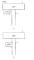
- the holding part 11 may be arranged in the air tube 10 as shown in FIG. 2B, or may be arranged in the air bag 13 as shown in FIG. Good.
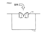
- FIG. 3 is a diagram illustrating a specific example of the configuration of the holding unit 11.
- holding portion 11 includes a holding space 11 ⁇ / b> A for holding air therein, and a check valve 11 ⁇ / b> B arranged at a boundary position between air tube 10 or air bag 13.
- the size of the holding space 11A is not limited to a specific size as long as the volume thereof is sufficiently smaller than the volume of the air bag 13. Specifically, if it is small enough not to affect the calculation of the blood pressure value based on the change in the internal pressure of the air bag 13 and can hold the amount of air that generates air pressure that can be detected by the pressure sensor 23. Good.
- the air inside the air tube 10 or the air bladder 13 is introduced into the holding space 11A through the check valve 11B.
- the check valve 11B is blocked from the inside to the air tube 10 or the air bag 13 and is not freely exhausted. Therefore, air is held in the holding space 11A by the volume of the space.
- the check valve 11B is slightly opened as indicated by the arrow B in FIG. 3 when a certain amount of pressure is applied from the holding space 11A side. Therefore, by applying a certain amount of pressure to the holding part 11, the air inside thereof is exhausted to the air pipe 10 or the air bag 13 through the check valve 11 ⁇ / b> B.
- a certain level of pressure is assumed to be a pressure at which a person strikes the holding unit 11.
- the measurement operation of the sphygmomanometer 1 starts when a measurement band (not shown) containing the air bag 13 is wound around the measurement site such as the wrist or the upper arm and the air bag 13 is attached and the start of measurement is instructed. Is done.
- the measurement operation involves the internal pressure control of the air bladder 13 that is depressurized after the internal pressure of the air bladder 13 is increased to a predetermined pressure higher than the maximum blood pressure value of the person being measured.
- the CPU 40 calculates the blood pressure value (maximum blood pressure value, minimum blood pressure value, etc.) of the measurement subject from the pulse pressure change superimposed on the internal pressure change of the air bladder 13 during the pressurization process or the decompression process.
- the measurement operation is started by the measurement person performing an operation of tapping the measurement band. Therefore, the measurer starts the measurement at the position where the measurement band is wound around the measurement site without returning to the main body where the operation unit 3 is arranged after the measurement zone is wound around the measurement site of the measurement subject. Can be directed.
- FIG. 4 is a block diagram showing a specific example of a functional configuration of the sphygmomanometer 1 for performing the above operation.
- the functions shown in FIG. 4 are mainly formed on the CPU 40 when the CPU 40 reads out and executes a program stored in the memory 6, but at least a part of the apparatus shown in FIG. It may be realized by a hardware configuration such as a configuration or an electric circuit.
- CPU 40 determines whether or not to start a measurement operation based on input unit 401 for receiving an input of a sensor signal from pressure sensor 23 and a change in internal pressure of air bladder 13 obtained from the sensor signal.
- a determination unit 402 for determining whether the measurement operation is started by the determination unit 402, an internal pressure control unit 403 for controlling the internal pressure of the air bag 13, and a pressure sensor under control of the internal pressure of the air bag 13.
- a calculation unit 404 for calculating a blood pressure value based on the change in the internal pressure of the air bladder 13 obtained from the sensor signal 23, and a display for performing processing for displaying the calculated blood pressure value on the display unit 4 as a measurement result.
- the determination by the determination unit 402 will be described. As described above, by applying pressure to the measurement band after the measurement band including the air bag 13 is wound around the measurement site, the air held in the holding unit 11 passes through the check valve 11B and the air tube 10 or Since the air bag 13 is exhausted, the internal pressure of the air bag 13 changes.
- the measurement site is the upper arm
- the arm around which the measurement band is wound may be on the lower side of the body when the measurement subject performs an action such as turning over, and pressure may be continuously applied to the measurement band.
- pressure may be instantaneously applied to the measurement zone by the person to be measured performing the operation of raising and lowering the arm.
- FIG. 5A shows an example of a change in the internal pressure of the air bag 13 in the former case
- FIG. 5B shows an example of a change in the internal pressure of the air bag 13 in the latter case.
- the determination unit 402 stores an internal pressure change pattern in advance, and determines that the measurement operation is started when the measured pressure sensor matches the pattern or the correlation is higher than a predetermined value.
- the determination unit 402 may store an internal pressure change pattern as shown in FIG.
- the internal pressure change pattern include parameters such as the number of times pressure is applied (pressure change), the time interval, the degree of change, and the maximum pressure value / minimum pressure value. As an example, all these parameters may be stored, or at least one of these parameters may be stored.
- the determination unit 402 calculates each parameter from the pressure sensor of the air bladder 13 for a predetermined period from the sensor signal, and determines whether it matches each parameter representing a prescribed pressure change pattern or is within a predetermined range. Thus, it is determined whether or not to start the measurement operation.
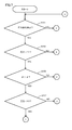
- ⁇ Operation flow> 7 and 8 are flowcharts showing the flow of operations up to the start of the measurement operation in the sphygmomanometer 1.
- the operation shown in the flowcharts of FIGS. 7 and 8 is an operation started when a power switch (not shown) included in the operation unit 3 is pressed to turn on the sphygmomanometer 1. This is realized by reading out and executing a stored program to exhibit each function shown in FIG.
- CPU 40 calculates each parameter and compares it with each parameter of the prescribed pressure change. That is, for the first pressure change, the pressure value is calculated to determine whether or not the pressure value is greater than the prescribed pressure P1 (step S103), and the slope d1 indicating the degree of the pressure change is further determined. It is calculated, and it is determined whether or not the calculated slope d1 is larger than the specified change degree ⁇ (step S105). Then, the subsequent pressure value is calculated, and it is determined whether or not the calculated pressure value has reached a pressure smaller than the pressure P3 (step S107).
- the CPU 40 determines that the first pressure change pattern shown in FIG. 6 has been performed, and proceeds to the next determination (YES in steps S103 to S107). ).
- the CPU 40 calculates each parameter for the second pressure change, and compares it with each parameter of the prescribed pressure change pattern. That is, the pressure value is calculated to determine whether or not it is greater than the pressure P2 (step S109), and further, it is determined whether or not the time interval t1 from the previous pressure change is longer than the prescribed time T ( In step S111, it is determined whether or not the slope d2 indicating the degree of pressure change is greater than the specified change degree ⁇ (step S103).
- the CPU 40 determines that the pressure change pattern defined in the second time shown in FIG. 6 has been performed (YES in steps S109 to S113). That is, it is determined that the pressure change pattern shown in FIG. 6 has been executed, and the blood pressure measurement operation is determined to start (step S115).
- step S101 If the conditions in FIGS. 8 and 9 are not satisfied (that is, NO in each of steps S101, S103, S105, S107, S109, S111, and S113), the process returns to the standby state, and the processes in and after step S101 are repeated. It is.
- the measurer By performing the above operation in the sphygmomanometer 1, the measurer wraps the measurement band around the measurement site of the person to be measured and then returns the measurement zone to the measurement site without returning to the main body where the operation unit 3 is arranged.
- the measurement start can be instructed at the position where the winding operation is performed. Therefore, a special configuration can be realized without requiring a sphygmomanometer 1. Therefore, it is possible to significantly improve the business efficiency while suppressing the device price.
Landscapes
- Health & Medical Sciences (AREA)
- Life Sciences & Earth Sciences (AREA)
- Cardiology (AREA)
- Vascular Medicine (AREA)
- Biomedical Technology (AREA)
- Molecular Biology (AREA)
- Physiology (AREA)
- Biophysics (AREA)
- Pathology (AREA)
- Engineering & Computer Science (AREA)
- Veterinary Medicine (AREA)
- Heart & Thoracic Surgery (AREA)
- Medical Informatics (AREA)
- Physics & Mathematics (AREA)
- Surgery (AREA)
- Animal Behavior & Ethology (AREA)
- General Health & Medical Sciences (AREA)
- Public Health (AREA)
- Ophthalmology & Optometry (AREA)
- Dentistry (AREA)
- Measuring Pulse, Heart Rate, Blood Pressure Or Blood Flow (AREA)
Description
また、リモートコントローラ本体を管理したり、カフを上腕などに巻き付けた後にリモートコントローラを取り出して操作したりといった、使用者の手間が増える問題があった。
断する。
図1は、本実施の形態にかかる電子血圧計(以下、血圧計)1の構成の具体例を示すブロック図である。
図3を参照して、保持部11は、その内部に空気を保持するための保持空間11Aと、エア管10または空気袋13との境界位置に配される逆止弁11Bとを含む。
<動作概要>
血圧計1での測定動作は、空気袋13を内包した測定帯(不図示)を手首や上腕などの測定部位に巻き回して空気袋13を装着した上で、測定開始が指示されると開始される。
図4は、上記動作を行なうための、血圧計1の機能構成の具体例を示すブロック図である。図4に示される各機能は、CPU40がメモリ6に記憶されるプログラムを読み出して実行することで、主にCPU40上に形成されるものであるが、少なくとも一部が図1に示された装置構成や電気回路などのハードウェア構成によって実現さあれてもよい。
上述のように、空気袋13を内包した測定帯を測定部位に巻き回した後に測定帯に圧力を加えることで、保持部11に保持された空気が逆止弁11Bを通ってエア管10または空気袋13に排気されるため、空気袋13の内圧が変化する。
図7および図8は、血圧計1での測定動作開始までの動作の流れを表わすフローチャートである。図7および図8のフローチャートに示される動作は、操作部3に含まれる図示しない電源スイッチが押下されて血圧計1に電源が投入されると開始される動作であって、CPU40がメモリ6に記憶されるプログラムを読み出して実行し、図4に示される各機能を発揮させることによって実現される。
血圧計1において以上の動作が行なわれることで、測定者は、測定帯を被測定者の測定部位に巻き付けた後に、操作部3の配された本体まで戻ることなく、測定帯を測定部位に巻き付ける動作を行なった位置にて測定開始を指示することができる。また、そのために、特別な構成を血圧計1に必要とせずに実現することができる。そのため、装置価格を抑えつつ業務効率を格段に向上させることができる。
Claims (5)
- 被測定者の測定部位に装着するための流体袋(13)と、
前記流体袋の内圧を測定するためのセンサ(23)と、
前記流体袋の内圧を調整するための調整機構と、
前記センサおよび前記調整機構に接続され、前記調整機構での前記調整を制御し、前記調整下での前記流体袋の内圧変化に基づいて血圧値を算出する処理を行なうための処理装置(40)と、
前記流体袋に対して流体の流入出が可能な、前記流体袋よりも小さい容量の流体保持部(11)とを備え、
前記流体保持部から前記流体袋に対しては、前記流体保持部に対して所定圧力が加えられた場合に流体が流出可能であって、
前記処理装置は、前記調整機構での前記調整の開始以前に前記センサで検出された前記流体袋の内圧変化が予め規定された変化である場合に、前記調整機構での前記調整を開始する、電子血圧計。 - 前記処理装置は、前記センサで検出された前記流体袋の内圧変化から予め規定されたパラメータを算出し、前記予め規定された変化に応じて予め記憶されているパラメータと比較することで、前記センサで検出された前記流体袋の内圧変化が予め規定された変化であるか否かを判断する、請求項1に記載の電子血圧計。
- 前記パラメータは、圧力変化の回数、圧力変化の時間間隔、各圧力変化での変化度合い、および各圧力変化での最大圧力値または最低圧力値、のうちの少なくとも1つである、請求項2に記載の電子血圧計。
- 前記処理装置は、前記センサで検出された前記流体袋の内圧変化の回数が予め記憶されている回数であり、その時間間隔が規定された予め記憶されている時間以上であり、前記センサで検出された前記流体袋の各内圧変化での変化度合いが予め記憶された変化度合い以上であり、前記センサで検出された前記流体袋の各内圧変化での最大圧力値が予め記憶されている圧力値以上である場合に、前記センサで検出された前記流体袋の内圧変化が予め規定された変化であると判断して、前記調整機構での前記調整を開始する、請求項2または3に記載の電子血圧計。
- 電子血圧計を用いて血圧測定を行なうための制御方法であって、
前記電子血圧計は、被測定者の測定部位に装着するための流体袋(13)と、前記流体袋に対して流体の流入出が可能な、前記流体袋よりも小さい容量の流体保持部(11)とを含み、前記流体保持部から前記流体袋に対しては、前記流体保持部に対して所定圧力が加えられた場合に流体が流出可能であって、
前記制御方法は、
血圧測定動作開始以前に、前記流体袋の内圧変化を検出するステップと、
前記流体袋の内圧変化と、予め規定された変化とを比較するステップと、
前記流体袋の内圧変化が前記予め規定された変化である場合に、前記流体袋の内圧制御を開始するステップと、
前記流体袋の内圧制御下で検出された前記流体袋の内圧変化に基づいて、前記被測定者の血圧値を算出するステップと、
前記算出された血圧値を出力するステップとを備える、電子血圧計の制御方法。
Priority Applications (3)
| Application Number | Priority Date | Filing Date | Title |
|---|---|---|---|
| DE112012005751.1T DE112012005751T5 (de) | 2012-01-27 | 2012-10-29 | Elektronisches Blutdruckmessgerät und Steuerverfahren davon |
| CN201280066144.6A CN104023622B (zh) | 2012-01-27 | 2012-10-29 | 电子血压计 |
| US14/372,404 US20150005649A1 (en) | 2012-01-27 | 2012-10-29 | Electronic blood pressure meter and control method thereof |
Applications Claiming Priority (2)
| Application Number | Priority Date | Filing Date | Title |
|---|---|---|---|
| JP2012-014746 | 2012-01-27 | ||
| JP2012014746A JP5867113B2 (ja) | 2012-01-27 | 2012-01-27 | 電子血圧計および電子血圧計の制御方法 |
Publications (1)
| Publication Number | Publication Date |
|---|---|
| WO2013111406A1 true WO2013111406A1 (ja) | 2013-08-01 |
Family
ID=48873148
Family Applications (1)
| Application Number | Title | Priority Date | Filing Date |
|---|---|---|---|
| PCT/JP2012/077856 Ceased WO2013111406A1 (ja) | 2012-01-27 | 2012-10-29 | 電子血圧計およびその制御方法 |
Country Status (5)
| Country | Link |
|---|---|
| US (1) | US20150005649A1 (ja) |
| JP (1) | JP5867113B2 (ja) |
| CN (1) | CN104023622B (ja) |
| DE (1) | DE112012005751T5 (ja) |
| WO (1) | WO2013111406A1 (ja) |
Cited By (2)
| Publication number | Priority date | Publication date | Assignee | Title |
|---|---|---|---|---|
| CN107049290A (zh) * | 2017-04-17 | 2017-08-18 | 北京大学 | 一种动态血压测量方法和系统 |
| CN112971751A (zh) * | 2019-12-12 | 2021-06-18 | 华为技术有限公司 | 测量血压的电子设备 |
Families Citing this family (1)
| Publication number | Priority date | Publication date | Assignee | Title |
|---|---|---|---|---|
| KR102506146B1 (ko) * | 2020-06-22 | 2023-03-06 | 주식회사 바디프랜드 | 혈압을 측정하는 마사지 장치 및 이의 제어 방법 |
Citations (3)
| Publication number | Priority date | Publication date | Assignee | Title |
|---|---|---|---|---|
| US6151968A (en) * | 1998-01-16 | 2000-11-28 | Chou; Deng-Jeng | Wrist band type electronic sphygmomanometer |
| JP2001198093A (ja) * | 2000-01-19 | 2001-07-24 | Terumo Corp | 電子血圧計 |
| JP2007195693A (ja) * | 2006-01-25 | 2007-08-09 | Matsushita Electric Works Ltd | 携帯型心電計測装置 |
Family Cites Families (6)
| Publication number | Priority date | Publication date | Assignee | Title |
|---|---|---|---|---|
| DE2265110C3 (de) * | 1972-08-07 | 1981-08-20 | Blasius 7455 Jungingen Speidel | Blutdruckmeßgerät |
| US5736702A (en) * | 1996-06-14 | 1998-04-07 | Dwyer Precision, Inc. | Pneumatic switch for patient call system having multiple-position housing assembly |
| US5916165A (en) * | 1997-11-06 | 1999-06-29 | Invasatec, Inc. | Pneumatic controller and method |
| CN2410977Y (zh) * | 2000-01-13 | 2000-12-20 | 叶健和 | 电子血压计的量测装置 |
| US6902531B2 (en) * | 2003-05-01 | 2005-06-07 | Ge Medical Systems Information Technologies, Inc. | Pneumatic control of blood pressure determinations |
| US7571008B2 (en) * | 2003-08-18 | 2009-08-04 | Medtronic, Inc. | System and apparatus for remote activation of implantable medical devices |
-
2012
- 2012-01-27 JP JP2012014746A patent/JP5867113B2/ja active Active
- 2012-10-29 WO PCT/JP2012/077856 patent/WO2013111406A1/ja not_active Ceased
- 2012-10-29 DE DE112012005751.1T patent/DE112012005751T5/de active Pending
- 2012-10-29 CN CN201280066144.6A patent/CN104023622B/zh active Active
- 2012-10-29 US US14/372,404 patent/US20150005649A1/en not_active Abandoned
Patent Citations (3)
| Publication number | Priority date | Publication date | Assignee | Title |
|---|---|---|---|---|
| US6151968A (en) * | 1998-01-16 | 2000-11-28 | Chou; Deng-Jeng | Wrist band type electronic sphygmomanometer |
| JP2001198093A (ja) * | 2000-01-19 | 2001-07-24 | Terumo Corp | 電子血圧計 |
| JP2007195693A (ja) * | 2006-01-25 | 2007-08-09 | Matsushita Electric Works Ltd | 携帯型心電計測装置 |
Cited By (2)
| Publication number | Priority date | Publication date | Assignee | Title |
|---|---|---|---|---|
| CN107049290A (zh) * | 2017-04-17 | 2017-08-18 | 北京大学 | 一种动态血压测量方法和系统 |
| CN112971751A (zh) * | 2019-12-12 | 2021-06-18 | 华为技术有限公司 | 测量血压的电子设备 |
Also Published As
| Publication number | Publication date |
|---|---|
| DE112012005751T5 (de) | 2014-11-20 |
| US20150005649A1 (en) | 2015-01-01 |
| JP5867113B2 (ja) | 2016-02-24 |
| CN104023622A (zh) | 2014-09-03 |
| CN104023622B (zh) | 2016-04-13 |
| JP2013153801A (ja) | 2013-08-15 |
Similar Documents
| Publication | Publication Date | Title |
|---|---|---|
| CN102307519B (zh) | 具有卷绕在测定部位上的袖袋的血压测定装置 | |
| CN102325492B (zh) | 管理装置、管理系统以及管理方法 | |
| JP5152153B2 (ja) | 電子血圧計 | |
| JP5853587B2 (ja) | 電子血圧計 | |
| US20130030310A1 (en) | Blood pressure measurement device | |
| JPWO2018168797A1 (ja) | 血圧測定装置、血圧測定方法及びプログラム | |
| US20100286539A1 (en) | Blood pressure measurement device for performing process taking change of measurement environment into consideration | |
| JP2010119446A (ja) | 血圧測定装置 | |
| CN107532746B (zh) | 用于控制便携式医疗装置的阀的系统和方法 | |
| US10165984B2 (en) | Configurable vital signs system | |
| US9022944B2 (en) | Electronic sphygmomanometer | |
| JP5867113B2 (ja) | 電子血圧計および電子血圧計の制御方法 | |
| JP2010158352A (ja) | 血圧測定装置 | |
| WO2013132696A1 (ja) | 血圧測定装置、血圧測定データ処理方法、及びプログラム | |
| JP5223590B2 (ja) | 血圧計 | |
| JP2009189619A (ja) | 血圧測定装置 | |
| JP6193161B2 (ja) | 血圧計試験装置、その制御方法及び血圧計システム | |
| CN118613238A (zh) | 用于分析加压疗法的使用的控制单元、系统及方法 | |
| JP2011152307A (ja) | 電子血圧計およびその制御方法 | |
| JP2013090824A (ja) | 電子血圧計 | |
| JP2012213444A (ja) | 血圧測定装置 | |
| US20260041328A1 (en) | Blood pressure monitoring system and method | |
| CN114727773B (zh) | 血压计、血压测量方法和程序 | |
| JP4693460B2 (ja) | 血圧測定装置 |
Legal Events
| Date | Code | Title | Description |
|---|---|---|---|
| 121 | Ep: the epo has been informed by wipo that ep was designated in this application |
Ref document number: 12866536 Country of ref document: EP Kind code of ref document: A1 |
|
| WWE | Wipo information: entry into national phase |
Ref document number: 14372404 Country of ref document: US |
|
| WWE | Wipo information: entry into national phase |
Ref document number: 1120120057511 Country of ref document: DE Ref document number: 112012005751 Country of ref document: DE |
|
| 122 | Ep: pct application non-entry in european phase |
Ref document number: 12866536 Country of ref document: EP Kind code of ref document: A1 |