WO2013108692A1 - 車両用アウターミラー - Google Patents
車両用アウターミラー Download PDFInfo
- Publication number
- WO2013108692A1 WO2013108692A1 PCT/JP2013/050217 JP2013050217W WO2013108692A1 WO 2013108692 A1 WO2013108692 A1 WO 2013108692A1 JP 2013050217 W JP2013050217 W JP 2013050217W WO 2013108692 A1 WO2013108692 A1 WO 2013108692A1
- Authority
- WO
- WIPO (PCT)
- Prior art keywords
- concave lens
- vehicle
- lens
- mirror
- outside
- Prior art date
- Legal status (The legal status is an assumption and is not a legal conclusion. Google has not performed a legal analysis and makes no representation as to the accuracy of the status listed.)
- Ceased
Links
Images


Classifications
-
- B—PERFORMING OPERATIONS; TRANSPORTING
- B60—VEHICLES IN GENERAL
- B60R—VEHICLES, VEHICLE FITTINGS, OR VEHICLE PARTS, NOT OTHERWISE PROVIDED FOR
- B60R1/00—Optical viewing arrangements; Real-time viewing arrangements for drivers or passengers using optical image capturing systems, e.g. cameras or video systems specially adapted for use in or on vehicles
- B60R1/10—Front-view mirror arrangements; Periscope arrangements, i.e. optical devices using combinations of mirrors, lenses, prisms or the like ; Other mirror arrangements giving a view from above or under the vehicle
Definitions
- the present invention relates to an outer mirror for a vehicle that makes it possible to visually recognize the front side of the passenger seat outside the passenger compartment.
- Patent Document 1 Conventionally, as such an outer mirror for a vehicle, a right-left mirror attached to a door mirror has been disclosed (see, for example, Patent Document 1).
- the straight left mirror described in Patent Document 1 is a front mirror that reflects light from the vicinity of the left front wheel portion of the vehicle toward the driver's viewpoint, and between the left front wheel portion and the left rear wheel portion of the vehicle. And a rear mirror that reflects light from the surroundings toward the driver's viewpoint.
- the two mirrors of the front mirror and the rear mirror it is possible to appropriately ensure the field of view around the left front wheel portion.
- each mirror is a convex mirror to widen the field of view of each mirror, the reflected image is reduced.
- each mirror is a concave mirror in order to enlarge the reflected image of each mirror, the field of view is narrowed.
- the direction of each mirror is restricted by the direction to be visually recognized and the position of the driver's viewpoint, the reflected image cannot be adjusted to be easily visible to the driver. Due to these restrictions, it is difficult to improve the visibility with the conventional vehicle outer mirror.
- An object of the present invention is to provide an outer mirror for a vehicle that can improve the visibility of the front side of the passenger seat outside the passenger compartment.
- An outer mirror for a vehicle is an outer mirror for a vehicle that makes it possible to visually recognize the front side of the passenger seat outside the passenger compartment, and a concave lens that transmits light from the front side, and light that has transmitted through the concave lens.
- a convex lens that is transmitted toward the interior of the room, a first reflecting mirror that is disposed above the concave lens and reflects light transmitted through the concave lens toward the front, and a first reflecting mirror that is disposed in front of the first reflecting mirror.
- a second reflecting mirror that reflects the light reflected by the mirror toward the vehicle interior.
- a wide range of images on the front side of the passenger seat outside the passenger compartment is captured upward from the concave lens.
- the captured image is reflected forward by the first reflecting mirror positioned above the concave lens, and becomes a reflected image that is easy to see with the front outside the vehicle compartment facing up and the rear outside the vehicle cabin facing down.
- the reflected image is reflected toward the vehicle interior by the second reflecting mirror located in front of the first reflecting mirror, magnified by the convex lens, and visually recognized by the driver.
- the driver can visually recognize a wide range of images on the front side of the front passenger seat outside the passenger compartment in a state where it is easily visible and in a size that is easily visible. Accordingly, the front side visibility on the passenger seat side outside the passenger compartment can be improved.
- the first and second reflecting mirrors may be disposed within the housing, the concave lens may be disposed outside the housing of the housing, and the convex lens may be disposed inside the housing of the housing.
- the housing prevents foreign matter from entering between the concave lens and the first reflecting mirror, between the first reflecting mirror and the second reflecting mirror, and between the second reflecting mirror and the convex lens.
- the concave lens is disposed outside the vehicle interior and the convex lens is disposed inside the vehicle interior, the image captured from the concave lens is visible to the driver without passing through the window glass of the vehicle. Therefore, the visibility of the front side on the passenger seat side outside the passenger compartment can be further improved.
- the focal point of the convex lens outside the passenger compartment may be located outside the focal point of the concave lens outside the passenger compartment. In this case, the image outside the passenger compartment captured from the concave lens can be more reliably enlarged and visually recognized by the driver.
- the convex lens is a plano-convex lens, and the convex surface of the convex lens may be directed into the vehicle interior. In this case, even if the amount of deviation between the optical axis of the convex lens and the viewpoint of the driver changes, the magnification of the image captured from the concave lens is unlikely to change, so the front side visibility on the passenger seat side outside the passenger compartment is further improved. Can be improved.
- the concave lens is a plano-concave lens, and the plane of the concave lens may be directed out of the passenger compartment. In this case, even if the amount of deviation between the optical axis of the concave lens and the object outside the passenger compartment changes, the magnification of the image of the object captured from the concave lens becomes difficult to change. The sex can be further improved.
- the concave lens may be a biconcave lens.
- the visual field range can be widened while suppressing distortion of the image outside the passenger compartment, and the front side visibility on the passenger seat side outside the passenger compartment can be further improved.
- each of the concave lens, the convex lens, the first reflecting mirror, and the second reflecting mirror is circular, and the outer diameter of each reflecting mirror is greater than or equal to the effective diameter of the concave lens, and the effective diameter of the convex lens is outside the reflecting mirror. It may be larger than the diameter.
- the outer diameter of each reflecting mirror is greater than or equal to the effective diameter of the concave lens, the image captured from the concave lens can be more reliably reflected toward the convex lens, so that the visual field range can be ensured.
- the effective diameter of the convex lens is larger than the outer diameter of each reflecting mirror. For this reason, since the image outside the vehicle compartment can be displayed toward the vehicle interior in a larger display area, the image outside the vehicle compartment can be further enlarged. Therefore, the visibility of the front side on the passenger seat side outside the passenger compartment can be further improved.
- each of the concave lens, the convex lens, the first reflecting mirror, and the second reflecting mirror is circular, and the outer diameter of each reflecting mirror may be larger than the effective diameter of the concave lens and larger than the effective diameter of the convex lens. .
- each of the reflecting mirrors can reflect a wider range of the image toward the convex lens, the field of view can be broadened, and the front side visibility on the passenger seat side outside the passenger compartment is further improved. be able to.
- the outer edge of the range visually recognized by the driver through the convex lens may be located inside the outer edge of the concave lens.
- the image captured from the concave lens can be enlarged by utilizing the entire area of the convex lens, and the front side visibility on the passenger seat side outside the passenger compartment can be further improved.
- the outer edge of the range visually recognized by the driver through the convex lens may be located outside the outer edge of the concave lens. In this case, since the outer edge of the concave lens can be visually recognized through the convex lens, the front side visibility on the passenger seat side outside the passenger compartment can be further improved.
- the front side visibility on the passenger seat side outside the passenger compartment can be improved.
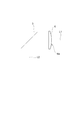
- FIG. 4 is a side view of the lens and reflecting mirror of FIG. 3. It is sectional drawing of a concave lens. It is sectional drawing of a convex lens.
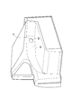
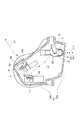
- the vehicle outer mirror 1 is disposed on the outer side of the mirror housing 4 and the mirror housing 4 incorporating the first reflecting mirror 2 and the second reflecting mirror 3.
- a concave lens 5 and a convex lens 6 disposed on the interior side of the mirror housing 4 are provided.
- the vehicle outer mirror 1 is provided above the front wheel on the passenger seat side of the vehicle 7. 1 to 3, the vehicle 7 is a right-hand drive vehicle, and the vehicle outer mirror 1 is provided above the left front wheel 7 a of the vehicle 7.
- the mirror housing 4 made of a resin material is attached to the left front portion of the vehicle 7 and has an exterior 4a outside the vehicle compartment and an interior 4b inside the vehicle compartment.
- a light incident port 4c is formed in the outdoor portion 4a downward, and a concave lens 5 is disposed in the outdoor portion 4a so as to close the light incident port 4c.
- the center of the light entrance 4c and the concave lens 5 and the center of the left front wheel 7a are substantially at the same position.
- a light exit 4d is formed in the interior 4b toward the vehicle interior, and a convex lens 6 is disposed in the interior 4b so as to correspond to the light exit 4d.
- the light exit 4 d is closed by the transparent panel 20.
- the concave lens 5 is a circular biconcave lens made of acrylic, for example (see FIG. 5).
- the concave lens 5 transmits light from the outside of the passenger compartment into the mirror housing 4.
- a support member 8 is fixed to the lower part in the mirror housing 4, and the outer peripheral portion of the concave lens 5 is supported by the support member 8.
- the material of the concave lens 5 is not limited to acrylic, but may be other general optical materials, that is, glass, polycarbonate, polyolefin, or the like.
- the convex lens 6 is a circular plano-convex lens made of acrylic, for example, and the convex surface 6a of the convex lens 6 is directed to the vehicle interior (see FIG. 6).
- the convex lens 6 transmits light from the mirror housing 4 into the vehicle interior.
- a support member 9 is fixed to the lower part of the mirror housing 4, and the outer peripheral portion of the convex lens 6 is supported by the support member 9.
- the material of the convex lens 6 is not limited to acrylic, but may be other general optical materials, that is, glass, polycarbonate, polyolefin, or the like.
- the reflecting mirrors 2 and 3 are, for example, flat mirrors in which a reflecting film is formed on one side of a glass disk.
- the 1st reflective mirror 2 is arrange
- the reflecting surface 2a of the first reflecting mirror 2 is directed to the front right and downward.
- the light that has entered the mirror housing 4 from below along the optical axis L1 is reflected by the reflecting surface 2a and travels forward to the right.
- a support member 10 is fixed to the lower part of the mirror housing 4, and the first reflecting mirror 2 is supported by the support member 10 from the opposite side of the reflecting surface 2 a.
- the second reflecting mirror 3 is arranged on the right front side of the first reflecting mirror 2 and on the left front side of the convex lens 6.
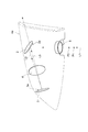
- the second reflecting mirror 3 is located on the optical path L2 of the light that is reflected by the reflecting surface 2a and travels forward to the right, and is located on the optical axis L3 of the convex lens 6 (see FIG. 4).
- the reflecting surface 3a of the second reflecting mirror 3 is directed rearward.
- the light traveling right forward along the optical path L2 is reflected by the reflecting surface 3a and travels right rear along the optical axis L3.
- a support member 11 is fixed to the lower part of the mirror housing 4, and the second reflecting mirror 3 is supported by the support member 11 from the opposite side of the reflecting surface 3 a.
- a wide-range image on the front side of the passenger seat outside the passenger compartment of the vehicle 7 is captured upward from the concave lens 5.
- the captured image is reflected right front by the first reflecting mirror 2 positioned above the concave lens 5, and becomes a reflected image that is easy to visually recognize, with the front outside the cabin facing up and the rear outside the cabin facing down.
- the reflected image is reflected toward the vehicle interior by the second reflecting mirror 3 located on the right front side of the first reflecting mirror 2, magnified by the convex lens 6, and visually recognized by the driver.
- the driver can visually recognize a wide range of images on the front side of the front passenger seat outside the passenger compartment in a state where it is easily visible and in a size that is easily visible. Accordingly, the front side visibility on the passenger seat side outside the passenger compartment can be improved.
- the reflecting mirrors 2 and 3 are arranged in the mirror housing 4, the concave lens 5 is arranged in the outdoor part 4 a of the mirror housing 4, and the convex lens 6 is arranged in the indoor part 4 b of the mirror housing 4.
- foreign matter enters between the concave lens 5 and the first reflecting mirror 2, between the first reflecting mirror 2 and the second reflecting mirror 3, and between the second reflecting mirror 3 and the convex lens 6. Is prevented by the mirror housing 4.
- the concave lens 5 is disposed outside the vehicle interior and the convex lens 6 is disposed on the vehicle interior side, the image captured from the concave lens 5 is visible to the driver without passing through the window glass of the vehicle 7. Therefore, the visibility of the front side on the passenger seat side outside the passenger compartment can be further improved.
- the concave lens 5 is a biconcave lens, a wider range of images can be captured from the concave lens 5 without increasing the curvature of the concave surface than when the concave lens 5 is a plano-concave lens, that is, without reducing the radius of curvature of the concave surface. Can do. For this reason, the visual field range can be widened while suppressing distortion of the image outside the passenger compartment, and the front side visibility on the passenger seat side outside the passenger compartment can be further improved.
- the convex lens 6 is a plano-convex lens, and the convex surface of the convex lens 6 is directed toward the vehicle interior. As a result, even if the amount of deviation between the optical axis L3 of the convex lens 6 and the viewpoint of the driver changes, the magnification of the image captured from the concave lens 5 is unlikely to change. The sex can be further improved.
- the center of the concave lens 5 and the center of the front wheel 7a on the passenger seat side are substantially the same position, the image around the front wheel 7a is reliably captured from the concave lens 5. Therefore, it is possible to improve the visibility around the front wheel 7a on the passenger seat side, which is likely to be a blind spot of the driver.
- the focal point P1 of the convex lens 6 outside the passenger compartment is located outside the focal point P2 of the concave lens 5 outside the passenger compartment.
- the focal point P1 outside the passenger compartment of the convex lens 6 means that the parallel light incident on the convex lens 6 from the passenger compartment along the optical axis L3 of the convex lens 6 outside the passenger compartment passes through the reflecting mirrors 2 and 3 without considering the concave lens 5. It is the point which condenses.
- the focal point P2 outside the passenger compartment of the concave lens 5 is a virtual condensing point of parallel light incident on the concave lens 5 from outside the passenger compartment along the optical axis L1 of the concave lens 5.
- the focal point P1 outside the passenger compartment of the convex lens 6 is located outside the focal point P2 outside the passenger compartment of the concave lens 5, the image outside the passenger compartment captured from the concave lens 5 can be more reliably magnified to the driver. It can be visually recognized.
- the outer diameter of the reflecting mirrors 2 and 3 is larger than the effective diameter of the concave lens 5 and larger than the effective diameter of the convex lens 6.
- the outer diameter of the range that is visible to the driver through the convex lens 6 at the position where the concave lens 5 is disposed is larger than the outer diameter of the concave lens 5. That is, the outer edge of the range visually recognized by the driver through the convex lens 6 is located outside the outer edge of the concave lens 5. Thereby, since the outer edge of the concave lens 5 can be visually recognized through the convex lens 6, the front side visibility on the passenger seat side outside the passenger compartment can be further improved.
- the outer diameter and outer edge of the concave lens 5 are the outer diameter and outer edge of the surface of the concave lens 5 exposed in the mirror housing 4.
- the outer diameter of the reflecting mirrors 2 and 3 may be greater than or equal to the effective diameter of the concave lens 5, and the effective diameter of the convex lens 6 may be larger than the outer diameter of the reflecting mirrors 2 and 3.
- the outer diameter of the reflecting mirrors 2 and 3 is equal to or larger than the effective diameter of the concave lens 5, the image captured from the concave lens 5 can be more reliably reflected toward the convex lens 6. can do.
- the effective diameter of the convex lens 6 is larger than the outer diameter of the reflecting mirrors 2 and 3, the light exit port 4d can be enlarged.
- the light exit 4d functions as a display area for displaying an image outside the vehicle interior toward the vehicle interior.
- the outer diameter in the range visually recognized by the driver through the convex lens 6 may be smaller than the effective diameter of the concave lens 5 at the position where the concave lens 5 is disposed. That is, the outer edge of the range visually recognized by the driver through the convex lens 6 may be located inside the outer edge of the concave lens 5. In this case, the image captured from the concave lens 5 can be enlarged by utilizing the entire area of the convex lens 6, and the front side visibility on the passenger seat side outside the passenger compartment can be further improved.
- the concave lens 5 may be a plano-concave lens whose plane is directed outside the passenger compartment. In this case, even if the amount of deviation between the optical axis L1 of the concave lens 5 and the object outside the passenger compartment changes, the magnification of the image of the object captured from the concave lens 5 is unlikely to change, so the front side of the passenger seat outside the passenger compartment The visibility of the direction can be further improved.
- the convex lens 6 may be a biconvex lens.
- the enlargement ratio of the image outside the passenger compartment can be increased without increasing the curvature of the convex surface, that is, without decreasing the curvature radius of the convex surface, compared to using a plano-convex lens. For this reason, it is possible to increase the enlargement ratio of the image while suppressing distortion of the image outside the passenger compartment, and it is possible to further improve the front side visibility on the passenger seat side outside the passenger compartment.
- the outer shape of the concave lens 5, the convex lens 6, and the reflecting mirrors 2 and 3 is not limited to a circle, and these outer shapes can be changed into various shapes in consideration of installation space and visibility.
- these outer shapes may be elliptical, may be polygonal shapes such as a triangle, a quadrangle, or a pentagon, and the corners of these polygons may be rounded.
- the inner surface of the mirror housing 4 may be made black by painting or the like. In this case, the image outside the passenger compartment becomes relatively clear with respect to the image on the inner surface of the mirror housing 4. Therefore, the visibility outside the passenger compartment can be improved.
- the present invention can be used for a vehicle outer mirror.
- SYMBOLS 1 Outer mirror for vehicles, 2 ... 1st reflective mirror, 3 ... 2nd reflective mirror, 4 ... Mirror housing, 5 ... Concave lens, 6 ... Convex lens, L1 ... Optical axis, L2 ... Optical path, L3 ... Optical axis.
Landscapes
- Engineering & Computer Science (AREA)
- Multimedia (AREA)
- Mechanical Engineering (AREA)
- Rear-View Mirror Devices That Are Mounted On The Exterior Of The Vehicle (AREA)
Description
本発明は、車室外における助手席側の前側方を視認可能にする車両用アウターミラーに関する。
従来、このような車両用アウターミラーとして、ドアミラーに取り付けられる直左鏡が開示されている(例えば、特許文献1参照)。特許文献1に記載された直左鏡は、車両の左側前輪部の周辺からの光を運転者の視点に向かって反射させる前方鏡と、車両の左側前輪部と左側後輪部との間の周辺からの光を運転者の視点に向かって反射させる後方鏡とを備えている。このように、前方鏡と後方鏡との2枚の鏡を備えることによって、左側前輪部周辺の視界を適切に確保することができる。
しかしながら、前述した従来の車両用アウターミラーでは、各鏡による視野を広げるために各鏡を凸面鏡にすると反射像が縮小されてしまう。一方、各鏡の反射像を拡大するために各鏡を凹面鏡にすると視野範囲が狭くなってしまう。また、各鏡の向きは視認すべき方向と運転者の視点の位置とによって制約されるため、反射像を運転者が視認し易い状態に調整することができない。これらの制約から、従来の車両用アウターミラーでは視認性の向上を図ることが難しい。
本発明は、車室外における助手席側の前側方の視認性を向上させることができる車両用アウターミラーを提供することを目的とする。
本発明に係る車両用アウターミラーは、車室外における助手席側の前側方を視認可能にする車両用アウターミラーであって、前側方からの光が透過する凹レンズと、凹レンズを透過した光が車室内に向かって透過する凸レンズと、凹レンズの上方に配置され、凹レンズを透過した光を前方に向かって反射させる第1の反射鏡と、第1の反射鏡の前方に配置され、第1の反射鏡で反射した光を車室内に向かって反射させる第2の反射鏡と、を備えることを特徴とする。
このような車両用アウターミラーでは、車室外における助手席側の前側方の広範囲の像が、凹レンズから上方に向かって取り込まれる。取り込まれた像は、凹レンズの上方に位置する第1の反射鏡によって前方に反射され、車室外の前方が上を向き車室外の後方が下を向いた視認し易い反射像となる。この反射像は、第1の反射鏡の前方に位置する第2の反射鏡により車室内に向かって反射され、凸レンズで拡大されて運転者に視認される。このように、車室外における助手席側の前側方の広範囲の像を視認し易い状態で且つ視認し易い大きさで運転者が視認することができる。従って、車室外における助手席側の前側方の視認性を向上させることができる。
第1及び第2の反射鏡はハウジング内に配置され、凹レンズはハウジングの車室外側に配置され、凸レンズはハウジングの車室内側に配置されていてもよい。この場合、凹レンズと第1の反射鏡との間、第1の反射鏡と第2の反射鏡との間、第2の反射鏡と凸レンズとの間への異物の侵入がハウジングによって防止される。更に、凹レンズは車室外側に配置され、凸レンズは車室内側に配置されているため、凹レンズから取り込まれた像は車両のウィンドウガラスを経ずに運転者に視認される。従って、車室外における助手席側の前側方の視認性をより向上させることができる。
凸レンズの車室外側の焦点は、凹レンズの車室外側の焦点よりも外側に位置してもよい。この場合、凹レンズから取り込まれた車室外の像をより確実に拡大して運転者に視認させることができる。
凸レンズは平凸レンズであり、凸レンズの凸面は車室内に向けられていてもよい。この場合、凸レンズの光軸と運転者の視点とのずれ量が変わっても、凹レンズから取り込まれた像の拡大率は変わり難くなるので、車室外における助手席側の前側方の視認性をより向上させることができる。
凹レンズは平凹レンズであり、凹レンズの平面は車室外に向けられていてもよい。この場合、凹レンズの光軸と車室外の物体とのずれ量が変わっても、凹レンズから取り込まれたその物体の像の拡大率は変わり難くなるので、車室外における助手席側の前側方の視認性をより向上させることができる。
凹レンズは両凹レンズであってもよい。この場合、凹レンズが平凹レンズであるのに比べ凹面の曲率を大きくすることなく、すなわち凹面の曲率半径を小さくすることなく、より広範囲の像を凹レンズから取り込むことができる。このため、車室外の像の歪みを抑制しながら視野範囲を広くすることができ、車室外における助手席側の前側方の視認性をより向上させることができる。
凹レンズと凸レンズと第1の反射鏡と第2の反射鏡とのそれぞれの外形は円形であり、各反射鏡の外径は凹レンズの有効径以上であり、凸レンズの有効径は各反射鏡の外径よりも大きくてもよい。この場合、各反射鏡の外径は凹レンズの有効径以上であることにより、凹レンズから取り込まれた像をより確実に凸レンズに向かって反射させることができるので、視野範囲を確保することができる。更に、凸レンズの有効径が各反射鏡の外径よりも大きい。このため、車室外の像をより大きい表示領域で車室内に向かって表示することができるので、車室外の像をより拡大することができる。従って、車室外における助手席側の前側方の視認性をより向上させることができる。
凹レンズと凸レンズと第1の反射鏡と第2の反射鏡とのそれぞれの外形は円形であり、各反射鏡の外径は凹レンズの有効径よりも大きく且つ凸レンズの有効径よりも大きくてもよい。この場合、各反射鏡によって、より広範囲の像を凸レンズに向かって反射させることができるので、視野範囲をより広くすることができ、車室外における助手席側の前側方の視認性をより向上させることができる。
凸レンズを通して運転者に視認される範囲の外縁は、凹レンズの外縁よりも内側に位置していてもよい。この場合、凹レンズから取り込まれた像を凸レンズの全域を活用して拡大し、車室外における助手席側の前側方の視認性をより向上させることができる。
凸レンズを通して運転者に視認される範囲の外縁は、凹レンズの外縁よりも外側に位置していてもよい。この場合、凸レンズを通して凹レンズの外縁を視認することができるので、車室外における助手席側の前側方の視認性をより向上させることができる。
本発明に係る車両用アウターミラーによれば、車室外における助手席側の前側方の視認性を向上させることができる。
以下、本発明に係る車両用アウターミラーの好適な実施形態について図面を参照しつつ詳細に説明する。図1~図3に示されるように、車両用アウターミラー1は、第1の反射鏡2及び第2の反射鏡3を内蔵したミラーハウジング4と、ミラーハウジング4の車室外側に配置された凹レンズ5と、ミラーハウジング4の車室内側に配置された凸レンズ6とを備えている。車両用アウターミラー1は、車両7の助手席側の前輪の上方に設けられている。図1~図3において、車両7は右ハンドル車であり、車両用アウターミラー1は車両7の左前輪7aの上方に設けられている。
例えば樹脂材料からなるミラーハウジング4は、車両7の左前部に取り付けられ、車室外側の室外部4aと車室内側の室内部4bとを有している。室外部4aには下方に向かって光入射口4cが形成され、室外部4a内には光入射口4cを塞ぐように凹レンズ5が配置されている。車両7の前後方向において、光入射口4c及び凹レンズ5の中心と左前輪7aの中心とは略同位置となっている。室内部4bには車室内に向かって光出射口4dが形成され、室内部4b内には光出射口4dに対応するように凸レンズ6が配置されている。光出射口4dは、透明パネル20により塞がれている。
凹レンズ5は、例えばアクリルからなる円形の両凹レンズである(図5参照)。凹レンズ5は、車室外からミラーハウジング4内に光を透過させる。ミラーハウジング4内の下部には支持部材8が固定され、凹レンズ5の外周部分は支持部材8によって支持されている。なお、凹レンズ5の材料はアクリルに限定されるものではなく、他の一般的な光学材料、すなわちガラス、ポリカーボネート、ポリオレフィン等であってもよい。
凸レンズ6は、例えばアクリルからなる円形の平凸レンズであり、凸レンズ6の凸面6aは車室内に向けられている(図6参照)。凸レンズ6は、ミラーハウジング4内から車室内に光を透過させる。ミラーハウジング4内の下部には支持部材9が固定され、凸レンズ6の外周部分は支持部材9によって支持されている。なお、凸レンズ6の材料はアクリルに限定されるものではなく、他の一般的な光学材料、すなわちガラス、ポリカーボネート、ポリオレフィン等であってもよい。
反射鏡2,3は、例えばガラスの円板の片面に反射膜が形成された平面鏡である。第1の反射鏡2は、凹レンズ5の上方に配置され、凹レンズ5の光軸L1上に位置している(図4参照)。第1の反射鏡2の反射面2aは、右前方且つ下方に向けられている。光軸L1に沿って下方からミラーハウジング4内に入射した光は、反射面2aで反射して右前方に進む。ミラーハウジング4内の下部には支持部材10が固定され、第1の反射鏡2は支持部材10によって反射面2aの逆側から支持されている。
第2の反射鏡3は、第1の反射鏡2の右前方且つ凸レンズ6の左前方に配置されている。第2の反射鏡3は、反射面2aで反射して右前方に進む光の光路L2上に位置すると共に凸レンズ6の光軸L3上に位置している(図4参照)。第2の反射鏡3の反射面3aは後方に向けられている。光路L2に沿って右前方に進む光は、反射面3aで反射し、光軸L3に沿って右後方に進む。ミラーハウジング4内の下部には支持部材11が固定され、第2の反射鏡3は支持部材11によって反射面3aの逆側から支持されている。
このような車両用アウターミラー1によれば、車両7の車室外の左前部において、下方の広範囲からの光が凹レンズ5に入射する。すなわち、車両7の車室外における助手席側の前側方の広範囲の像が凹レンズ5から上方に向かって取り込まれる。取り込まれた像は、凹レンズ5の上方に位置する第1の反射鏡2によって右前方に反射され、車室外の前方が上を向き車室外の後方が下を向いた視認し易い反射像となる。この反射像は、第1の反射鏡2の右前方に位置する第2の反射鏡3により車室内に向かって反射され、凸レンズ6で拡大されて運転者に視認される。このように、車室外における助手席側の前側方の広範囲の像を視認し易い状態で且つ視認し易い大きさで運転者が視認することができる。従って、車室外における助手席側の前側方の視認性を向上させることができる。
反射鏡2,3はミラーハウジング4内に配置され、凹レンズ5はミラーハウジング4の室外部4aに配置され、凸レンズ6はミラーハウジング4の室内部4bに配置されている。これにより、凹レンズ5と第1の反射鏡2との間、第1の反射鏡2と第2の反射鏡3との間、第2の反射鏡3と凸レンズ6との間への異物の侵入がミラーハウジング4によって防止される。更に、凹レンズ5は車室外側に配置され、凸レンズ6は車室内側に配置されているため、凹レンズ5から取り込まれた像は車両7のウィンドウガラスを経ずに運転者に視認される。従って、車室外における助手席側の前側方の視認性をより向上させることができる。
凹レンズ5は両凹レンズであることから、凹レンズ5が平凹レンズであるのに比べ凹面の曲率を大きくすることなく、すなわち凹面の曲率半径を小さくすることなく、より広範囲の像を凹レンズ5から取り込むことができる。このため、車室外の像の歪みを抑制しながら視野範囲を広くすることができ、車室外における助手席側の前側方の視認性をより向上させることができる。
凸レンズ6は平凸レンズであり、凸レンズ6の凸面は車室内に向けられている。これにより、凸レンズ6の光軸L3と運転者の視点とのずれ量が変わっても、凹レンズ5から取り込まれた像の拡大率は変わり難くなるので、車室外における助手席側の前側方の視認性をより向上させることができる。
凹レンズ5の中心と助手席側の前輪7aの中心とは略同位置となっているため、前輪7aの周囲の像が確実に凹レンズ5から取り込まれる。従って、運転者の死角となりやすい助手席側の前輪7aの周囲の視認性を向上させることができる。
次に、凹レンズ5と凸レンズ6と反射鏡2,3との関係について更に詳細に説明する。凹レンズ5、凸レンズ6、反射鏡2,3の仕様の具体例として、次のようなものが挙げられる。
凸レンズ6の主点と運転者の視点との距離:1736mm
凸レンズ6の光軸L3と反射鏡3の反射面3aとの交点と、凸レンズ6の主点との距離:84mm
凸レンズ6の車室外側の焦点距離:918mm
凸レンズ6の有効径:60mm
光路L2の距離:275.9mm
凹レンズ5の光軸L1と反射鏡2の反射面2aとの交点と、凹レンズ5の主点との距離:105mm
凹レンズ5の車室外側の焦点距離:51mm
凹レンズ5の有効径:46mm
凹レンズ5の外径:50mm
反射鏡2,3の外径:74mm
凸レンズ6の主点と運転者の視点との距離:1736mm
凸レンズ6の光軸L3と反射鏡3の反射面3aとの交点と、凸レンズ6の主点との距離:84mm
凸レンズ6の車室外側の焦点距離:918mm
凸レンズ6の有効径:60mm
光路L2の距離:275.9mm
凹レンズ5の光軸L1と反射鏡2の反射面2aとの交点と、凹レンズ5の主点との距離:105mm
凹レンズ5の車室外側の焦点距離:51mm
凹レンズ5の有効径:46mm
凹レンズ5の外径:50mm
反射鏡2,3の外径:74mm
この仕様では、凸レンズ6の車室外側の焦点P1は凹レンズ5の車室外側の焦点P2よりも外側に位置している。凸レンズ6の車室外側の焦点P1とは、凹レンズ5を考慮しない状態で、凸レンズ6の光軸L3に沿って車室内から凸レンズ6に入射した平行光が反射鏡2,3を経て車室外で集光する点である。凹レンズ5の車室外側の焦点P2とは、凹レンズ5の光軸L1に沿い車室外から凹レンズ5に入射した平行光の仮想集光点である。凸レンズ6の車室外側の焦点P1が凹レンズ5の車室外側の焦点P2よりも外側に位置していることにより、凹レンズ5から取り込まれた車室外の像をより確実に拡大して運転者に視認させることができる。
また、反射鏡2,3の外径は凹レンズ5の有効径よりも大きく且つ凸レンズ6の有効径よりも大きい。これにより、反射鏡2,3によって、より広範囲の像を凸レンズ6に向かって反射させることができるので、視野範囲をより広くすることができ、車室外における助手席側の前側方の視認性をより向上させることができる。
また、凹レンズ5が配置されている位置において、凸レンズ6を通して運転者に視認される範囲の外径は凹レンズ5の外径よりも大きい。すなわち、凸レンズ6を通して運転者に視認される範囲の外縁は、凹レンズ5の外縁よりも外側に位置している。これにより、凸レンズ6を通して凹レンズ5の外縁を視認することができるので、車室外における助手席側の前側方の視認性をより向上させることができる。凹レンズ5の外径及び外縁とは、凹レンズ5のミラーハウジング4内に露出する面の外径及び外縁である。
なお、反射鏡2,3の外径を凹レンズ5の有効径以上とし、凸レンズ6の有効径を反射鏡2,3の外径より大きくしてもよい。この場合、反射鏡2,3の外径は凹レンズ5の有効径以上であることにより、凹レンズ5から取り込まれた像をより確実に凸レンズ6に向かって反射させることができるので、視野範囲を確保することができる。更に、凸レンズ6の有効径が反射鏡2,3の外径よりも大きいことにより、光出射口4dを大きくすることができる。光出射口4dは、車室内に向けて車室外の像を表示する表示領域として機能する。このため、光出射口4dを大きくすると、車室外の像をより大きい表示領域で車室内に向かって表示することができるので、車室外の像をより拡大することができる。従って、車室外における助手席側の前側方の視認性をより向上させることができる。
また、凹レンズ5が配置されている位置において、凸レンズ6を通して運転者に視認される範囲の外径は凹レンズ5の有効径より小さくてもよい。すなわち、凸レンズ6を通して運転者に視認される範囲の外縁は、凹レンズ5の外縁よりも内側に位置していてもよい。この場合、凹レンズ5から取り込まれた像を凸レンズ6の全域を活用して拡大し、車室外における助手席側の前側方の視認性をより向上させることができる。
以上、本発明の好適な実施形態について説明してきたが、本発明は必ずしも上述した実施形態に限定されるものではなく、その要旨を逸脱しない範囲で様々な変更が可能である。
例えば、凹レンズ5は平面が車室外に向けられた平凹レンズであってもよい。この場合、凹レンズ5の光軸L1と車室外の物体とのずれ量が変わっても、凹レンズ5から取り込まれたその物体の像の拡大率は変わり難くなるので、車室外における助手席側の前側方の視認性をより向上させることができる。
また、凸レンズ6は両凸レンズであってもよい。この場合、平凸レンズを用いるのに比べ、凸面の曲率を大きくすることなく、すなわち凸面の曲率半径を小さくすることなく車室外の像の拡大率を高くすることができる。このため、車室外の像の歪みを抑制しながら像の拡大率を高くすることができ、車室外における助手席側の前側方の視認性をより向上させることができる。
また、凹レンズ5、凸レンズ6、反射鏡2,3の外形は円形に限られず、設置スペースや視認性を考慮して、これらの外形を様々な形状に変えることができる。例えば、これらの外形を楕円形としてもよく、三角形、四角形、又は五角形等の多角形状としてもよく、これらの多角形状の角部を丸めてもよい。
また、ミラーハウジング4の内面を塗装等によって黒色にしてもよい。この場合、ミラーハウジング4の内面の像に対して車室外の像が相対的に明瞭となる。従って、車室外の視認性をより良好にすることができる。
本発明は、車両用アウターミラーに利用できる。
1…車両用アウターミラー、2…第1の反射鏡、3…第2の反射鏡、4…ミラーハウジング、5…凹レンズ、6…凸レンズ、L1…光軸、L2…光路、L3…光軸。
Claims (10)
- 車室外における助手席側の前側方を視認可能にする車両用アウターミラーであって、
前記前側方からの光が透過する凹レンズと、
前記凹レンズを透過した前記光が車室内に向かって透過する凸レンズと、
前記凹レンズの上方に配置され、前記凹レンズを透過した前記光を前方に向かって反射させる第1の反射鏡と、
前記第1の反射鏡の前方に配置され、前記第1の反射鏡で反射した前記光を車室内に向かって反射させる第2の反射鏡と、を備えることを特徴とする車両用アウターミラー。 - 前記第1及び第2の反射鏡はハウジング内に配置され、
前記凹レンズは前記ハウジングの車室外側に配置され、
前記凸レンズは前記ハウジングの車室内側に配置されていることを特徴とする請求項1記載の車両用アウターミラー。 - 前記凸レンズの車室外側の焦点は、前記凹レンズの車室外側の焦点よりも外側に位置することを特徴とする請求項1又は2記載の車両用アウターミラー。
- 前記凸レンズは平凸レンズであり、
前記凸レンズの凸面は車室内に向けられていることを特徴とする請求項1~3のいずれか一項記載の車両用アウターミラー。 - 前記凹レンズは平凹レンズであり、
前記凹レンズの平面は車室外に向けられていることを特徴とする請求項1~4のいずれか一項記載の車両用アウターミラー。 - 前記凹レンズは両凹レンズであることを特徴とする請求項1~4のいずれか一項記載の車両用アウターミラー。
- 前記凹レンズと前記凸レンズと前記第1の反射鏡と前記第2の反射鏡とのそれぞれの外形は円形であり、
前記各反射鏡の外径は前記凹レンズの有効径以上であり、
前記凸レンズの有効径は前記各反射鏡の外径よりも大きいことを特徴とする請求項1~6のいずれか一項記載の車両用アウターミラー。 - 前記凹レンズと前記凸レンズと前記第1の反射鏡と前記第2の反射鏡とのそれぞれの外形は円形であり、
前記各反射鏡の外径は前記凹レンズの有効径よりも大きく且つ前記凸レンズの有効径よりも大きいことを特徴とする請求項1~6のいずれか一項記載の車両用アウターミラー。 - 前記凸レンズを通して運転者に視認される範囲の外縁は、前記凹レンズの外縁よりも内側に位置していることを特徴とする請求項1~8のいずれか一項記載の車両用アウターミラー。
- 前記凸レンズを通して運転者に視認される範囲の外縁は、前記凹レンズの外縁よりも外側に位置していることを特徴とする請求項1~8のいずれか一項記載の車両用アウターミラー。
Applications Claiming Priority (2)
| Application Number | Priority Date | Filing Date | Title |
|---|---|---|---|
| JP2012010323A JP2013147190A (ja) | 2012-01-20 | 2012-01-20 | 車両用アウターミラー |
| JP2012-010323 | 2012-01-20 |
Publications (1)
| Publication Number | Publication Date |
|---|---|
| WO2013108692A1 true WO2013108692A1 (ja) | 2013-07-25 |
Family
ID=48799118
Family Applications (1)
| Application Number | Title | Priority Date | Filing Date |
|---|---|---|---|
| PCT/JP2013/050217 Ceased WO2013108692A1 (ja) | 2012-01-20 | 2013-01-09 | 車両用アウターミラー |
Country Status (2)
| Country | Link |
|---|---|
| JP (1) | JP2013147190A (ja) |
| WO (1) | WO2013108692A1 (ja) |
Citations (7)
| Publication number | Priority date | Publication date | Assignee | Title |
|---|---|---|---|---|
| FR1079274A (fr) * | 1953-04-30 | 1954-11-29 | Dispositif rétroviseur, notamment pour automobiles et applications analogues | |
| JPS6285008A (ja) * | 1985-08-21 | 1987-04-18 | デイビツド ハ−バ−ト ブロウア− | 保護ヘルメツト |
| JPH05301540A (ja) * | 1992-04-28 | 1993-11-16 | Tokai Rika Co Ltd | 自動車の補助ミラー |
| EP0901937A1 (fr) * | 1997-09-10 | 1999-03-17 | Automobiles Peugeot | Rétroviseur pour véhicules automobiles |
| JP2001187547A (ja) * | 1999-12-02 | 2001-07-10 | Ford Global Technol Inc | 車両用画像取得及び表示組立体 |
| FR2820097A1 (fr) * | 2001-01-30 | 2002-08-02 | Peugeot Citroen Automobiles Sa | Retrovisseur a encombrement reduit a faible surface frontale |
| JP2009255727A (ja) * | 2008-04-16 | 2009-11-05 | Honda Motor Co Ltd | サイドアンダーミラー装置 |
-
2012
- 2012-01-20 JP JP2012010323A patent/JP2013147190A/ja active Pending
-
2013
- 2013-01-09 WO PCT/JP2013/050217 patent/WO2013108692A1/ja not_active Ceased
Patent Citations (7)
| Publication number | Priority date | Publication date | Assignee | Title |
|---|---|---|---|---|
| FR1079274A (fr) * | 1953-04-30 | 1954-11-29 | Dispositif rétroviseur, notamment pour automobiles et applications analogues | |
| JPS6285008A (ja) * | 1985-08-21 | 1987-04-18 | デイビツド ハ−バ−ト ブロウア− | 保護ヘルメツト |
| JPH05301540A (ja) * | 1992-04-28 | 1993-11-16 | Tokai Rika Co Ltd | 自動車の補助ミラー |
| EP0901937A1 (fr) * | 1997-09-10 | 1999-03-17 | Automobiles Peugeot | Rétroviseur pour véhicules automobiles |
| JP2001187547A (ja) * | 1999-12-02 | 2001-07-10 | Ford Global Technol Inc | 車両用画像取得及び表示組立体 |
| FR2820097A1 (fr) * | 2001-01-30 | 2002-08-02 | Peugeot Citroen Automobiles Sa | Retrovisseur a encombrement reduit a faible surface frontale |
| JP2009255727A (ja) * | 2008-04-16 | 2009-11-05 | Honda Motor Co Ltd | サイドアンダーミラー装置 |
Also Published As
| Publication number | Publication date |
|---|---|
| JP2013147190A (ja) | 2013-08-01 |
Similar Documents
| Publication | Publication Date | Title |
|---|---|---|
| US7652825B2 (en) | Cover for head-up display | |
| US7602553B2 (en) | Windshield and head-up display system | |
| JP6630921B2 (ja) | ヘッドアップディスプレイおよびヘッドアップディスプレイを搭載した移動体 | |
| WO2016079926A1 (ja) | ヘッドアップディスプレイ及び車両 | |
| JP2010208580A (ja) | ヘッドアップディスプレイ装置 | |
| WO2016038767A1 (ja) | ヘッドアップディスプレイ及び移動体 | |
| US10279735B2 (en) | Vehicle interior component | |
| JP6697750B2 (ja) | 車両用表示システム、電子ミラーシステム及びそれを備える移動体 | |
| JPWO2019163171A1 (ja) | ヘッドアップディスプレイおよびヘッドアップディスプレイを搭載した移動体 | |
| CN104111529A (zh) | 平视显示器的盖以及包含盖的外壳 | |
| JP6405627B2 (ja) | 死角補助装置 | |
| WO2012176548A1 (ja) | 車両用表示装置 | |
| JP6299471B2 (ja) | 死角補助装置 | |
| JP2017187528A (ja) | ヘッドアップディスプレイ装置 | |
| CN206086541U (zh) | 用于消除车辆a柱盲区的装置及包括该装置的车辆 | |
| JP2013052859A (ja) | 車両用アウターミラー | |
| WO2018186149A1 (ja) | ヘッドアップディスプレイシステム、およびヘッドアップディスプレイシステムを備える移動体 | |
| JP5302713B2 (ja) | 視野拡大構造 | |
| JP2013147190A (ja) | 車両用アウターミラー | |
| KR101596601B1 (ko) | 사이드 미러 | |
| WO2017057000A1 (ja) | 死角補助装置 | |
| US10347133B2 (en) | Optical device | |
| WO2013108682A1 (ja) | 車外視認装置 | |
| JP5785124B2 (ja) | 車外視認装置 | |
| JP2020148959A (ja) | 光学デバイス |
Legal Events
| Date | Code | Title | Description |
|---|---|---|---|
| 121 | Ep: the epo has been informed by wipo that ep was designated in this application |
Ref document number: 13738972 Country of ref document: EP Kind code of ref document: A1 |
|
| NENP | Non-entry into the national phase |
Ref country code: DE |
|
| 122 | Ep: pct application non-entry in european phase |
Ref document number: 13738972 Country of ref document: EP Kind code of ref document: A1 |