WO2013108482A1 - 涙道内挿管器具 - Google Patents
涙道内挿管器具 Download PDFInfo
- Publication number
- WO2013108482A1 WO2013108482A1 PCT/JP2012/080179 JP2012080179W WO2013108482A1 WO 2013108482 A1 WO2013108482 A1 WO 2013108482A1 JP 2012080179 W JP2012080179 W JP 2012080179W WO 2013108482 A1 WO2013108482 A1 WO 2013108482A1
- Authority
- WO
- WIPO (PCT)
- Prior art keywords
- lacrimal
- tube
- bougie
- passage
- intubation device
- Prior art date
- Legal status (The legal status is an assumption and is not a legal conclusion. Google has not performed a legal analysis and makes no representation as to the accuracy of the status listed.)
- Ceased
Links
Images



Classifications
-
- A—HUMAN NECESSITIES
- A61—MEDICAL OR VETERINARY SCIENCE; HYGIENE
- A61F—FILTERS IMPLANTABLE INTO BLOOD VESSELS; PROSTHESES; DEVICES PROVIDING PATENCY TO, OR PREVENTING COLLAPSING OF, TUBULAR STRUCTURES OF THE BODY, e.g. STENTS; ORTHOPAEDIC, NURSING OR CONTRACEPTIVE DEVICES; FOMENTATION; TREATMENT OR PROTECTION OF EYES OR EARS; BANDAGES, DRESSINGS OR ABSORBENT PADS; FIRST-AID KITS
- A61F9/00—Methods or devices for treatment of the eyes; Devices for putting in contact-lenses; Devices to correct squinting; Apparatus to guide the blind; Protective devices for the eyes, carried on the body or in the hand
- A61F9/007—Methods or devices for eye surgery
- A61F9/00772—Apparatus for restoration of tear ducts
Definitions
- the present invention relates to a lacrimal intubation device used for treatment of lacrimal passage obstruction.
- lacrimal nasal sinus anastomosis For treatment of lacrimal passage obstruction that induces lacrimation and dry eye, (a) lacrimal nasal sinus anastomosis, (b) lacrimal canal plasty, (c) nasolacrimal duct plasty, (d) lacrimal migration And (e) lacrimal tube intubation.
- the treatment methods (a) to (d) described above have a high therapeutic effect but a high degree of invasiveness because the incision is made in the face or the bone is pierced by piercing the lacrimal passage. There is a problem. Therefore, these procedures are often performed as a last resort.
- the treatment method (e) is selected as the first treatment and widely practiced because it is easier and less invasive than the treatment methods (a) to (d). ing.
- the lacrimal tube intubation is briefly described as follows. First, if necessary, a rod-like device called a bougie is inserted into the closed lacrimal passage, and the occlusion site is opened beforehand. Next, using the lacrimal tube into which the attached bougie is inserted (the lacrimal canal intubation device), the attached bougie is operated to guide the lacrimal tube into the lacrimal passage, and the lacrimal passage tube is inserted beyond the occlusion site. Is done. Thereafter, only the attached bougie is removed, the lacrimal duct tube is left in place, and the tube is removed when the lacrimal duct is spread and stabilized.
- the lacrimal tube intubation can completely open the occlusion site of the lacrimal passage and ensure normal lacrimal passage function again.
- an intra lacrimal intubation device including an attached bougie and a lacrimal tube is used.
- a nunchaku-type lacrimal tube is widely used as the lacrimal tube (see Patent Document 1).
- This nunchaku lacrimal tube is made of a soft tube or rod that is thin at the center of the tube, and a tube that is thicker and harder than the center at both sides. Has a structure inserted.
- the treatment method (e) is an effective treatment method in that the technique is easier and the invasiveness is lower than the treatment methods (a) to (d).
- the attached bougie may pierce the lacrimal duct and injure the lacrimal passage, and if it is more severe, a hole (temporary passage) may be made in addition to the normal lacrimal passage. Therefore, even with the treatment method (e), the therapeutic results were not always good.
- Intra lacrimal intubation device that is highly dependent on the experience, anatomical knowledge, and sense of operation of the surgeon, and can perform lacrimal tube intubation more safely even for an operator with little experience. Was demanded.
- the occlusion site has been opened to some extent in advance, the strength for passing through the occlusion site is reduced, and there is a possibility that a problem may occur in the insertion property of the lacrimal tube.
- the bougie will eventually move relative to the distal side of the lacrimal tube and break through the tube to break the lacrimal passage. May hurt or form a temporary road.
- a lacrimal canal intubation device that has a tip opening portion at both ends of the nunchaku-type lacrimal tube and that is provided with a stopper that restricts the bougie tip from protruding from the vicinity of the tip opening portion (patented) Reference 2)
- a lacrimal intubation device (see Patent Document 3) provided with a mark that can visually confirm that the tip of the bougie is at a predetermined position of the tube, and a wire portion constituted by a superelastic alloy wire
- a tube see Patent Document 4 into which a lacrimal tract bougie having a plug is inserted.
- the surgeon can directly detect that the tip of the bougie is in direct contact with the wall of the lacrimal passage. In addition, even if the bougie tip is exposed by the stopper, the bougie does not protrude from the tube carelessly.
- a bougie is inserted into a lacrimal tube having a distal end opening portion, for example, by providing a mark with which the relative positional relationship can be visually observed on the lacrimal tube and the attached bougie.
- the operator can visually confirm that the tube has crushed along the bougie due to the friction between the inner wall of the lacrimal tract and the lacrimal tract tube. It is said that if the insertion into the lacrimal passage is continued, the lacrimal wall surface is less likely to be damaged.
- the wire portion is composed of a superelastic alloy wire, so that the wire portion is elastically deformed (bent) to a relatively large strain amount due to the superelastic effect, and even if it is bent once. Since the shape recovers without causing bending folds, it is said that the shape can be bent relatively easily along the lacrimal passage, the workability is improved, and the possibility of damaging the lacrimal passage is reduced.
- an endoscope is used instead of a bougie, and the lacrimal duct tube is used in a non-blind manner. It is also possible to insert If an endoscope is used as a bougie, intubation is possible while grasping the inside of the lacrimal passage with a monitor, but it is necessary to perform an operation while confirming both the monitor image and the state of the bougie and lacrimal tube. Since the endoscope is long, handling of the bougie becomes difficult, and the work efficiency may be reduced. Therefore, at present, lacrimal tube intubation is often performed blindly without using an endoscope.
- tears that can be safely intubated into the lacrimal passage are reduced even when the lacrimal tube intubation is performed blindly, while maintaining the operability of the bougie and reducing the possibility of damaging the lacrimal passage.
- intubation devices There is a need for the development of intubation devices.
- the object of the present invention is to maintain the same operability as a conventional attached bougie (bougie) while damaging the lacrimal passage or forming a temporary passage even in a blind operation. It is an object of the present invention to provide an intra lacrimal intubation device with a reduced possibility of doing so.
- the inventors of the lacrimal canal intubation device by imparting flexibility to a predetermined position of the bougie as its constituent member, without impairing operability, It has been found that even if the operation is performed blindly, the possibility of damaging the lacrimal passage or forming a temporary passage is reduced, and the present invention has been completed.
- the gist of the present invention is as follows.
- a lacrimal intubation device comprising a tube placed in the lacrimal passage and a bougie inserted in the lumen of the tube so as to be detachable, the bougie at the distal end side of the lumen of the tube.
- the portion disposed in the portion has a portion disposed outside the tube on the base end side, and the portion disposed in the lumen portion of the tube is more acceptable than the portion disposed outside the tube.
- a lacrimal intubation device having a highly flexible portion.
- a lacrimal intubation device that maintains the same operability as a conventional attached bougie (bougie) and has reduced the possibility of damaging the lacrimal passage or forming a temporary tract even in a blind operation. Can be provided.
- the top view which shows one Embodiment of the lacrimal intubation device of this invention. Explanatory drawing which showed typically the anatomical structure of the lacrimal passage.
- the side view which shows an example of embodiment of the bougie which comprises the lacrimal intubation instrument of this invention.
- the side view which shows the other example of embodiment of the bougie which comprises the lacrimal duct intubation device of this invention.
- Schematic shows the evaluation method of a bougie.
- the lacrimal intubation device of the present invention includes a tube (also referred to as a lacrimal tract tube) that is placed in the lacrimal passage, and a bougie (also referred to as an attached bougie) that is detachably inserted into the lumen of the tube. .
- a tube also referred to as a lacrimal tract tube
- a bougie also referred to as an attached bougie
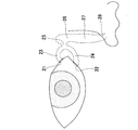
- the lacrimal passage referred to in the present invention is the upper / lower punctum (21/22), upper / lower lacrimal duct (23/24), total lacrimal duct (25), lacrimal sac (26) , Lacrimal duct (27), nasal duct (not shown), Hasner's valve (not shown), and lacrimal fluid produced from the lacrimal gland (not shown) is transferred from the ocular surface to the lower nasal passage (28 ) Is a tube (eyeball appendage) that leads to The tube leading from the upper punctum (21) to the lower nasal passage (28) through the upper lacrimal canal (23) and the total lacrimal canal (25) is called the upper lacrimal passage.
- the duct leading to the lower nasal passage (28) through the lacrimal canal (24) and the total lacrimal duct (25) is called the lower lacrimal passage.
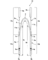
- FIG. 1 is a plan view showing an embodiment of an intra lacrimal intubation device according to the present invention.
- the lacrimal canal intubation device 10 according to this embodiment includes a tube 1 placed in the lacrimal passage and a pair of bougies 2 a and 2 b that are detachably inserted into the lumen of the tube 1. .
- the structure of the tube 1 is not particularly limited, but a tube provided with an integral tube placed in the lacrimal passage is preferable.
- integral means that the number of the two tubes inserted into each of the upper / lower lacrimal passages is one.
- the tube 1 has a cylindrical or rod-shaped central portion 4, which is a portion to be placed in the punctum, lacrimal tubule, total lacrimal tubule, and lacrimal sac at a substantially central portion. It is connected to one end of the part 4, and is connected to the other end of the cylindrical first cylindrical part 5a and the central part 4, which is a part placed in the lacrimal sac, nasolacrimal duct, Hasner's valve, lower nasal passage. It is provided with a lacrimal sac, a nasolacrimal duct, Hasner's valve, and a cylindrical second cylindrical portion 5b which is a part placed in the lower nasal passage, and is an integral tube.
- the center part 4 is thinner than the 1st cylindrical part 5a and the 2nd cylindrical part 5b, is formed flexibly, and is called what is called a nunchaku type lacrimal duct tube.
- the degree of flexibility of the central portion 4 is not particularly limited as long as it is more flexible than the cylindrical portions 5a and 5b, but when supported and lifted at the center point in the length direction of the tube 1, It is preferable that the central portion is flexible. The flexibility of the tube 1 can be adjusted by the type and size of the material described later.
- the integral tube placed in the lacrimal passage may have a substantially constant inner and outer diameter over the entire length, or within the practically acceptable range, the center in the embodiment of FIG.
- the portion corresponding to the portion 4 may have a larger outer diameter than the portions corresponding to the cylindrical portions 5a and 5b at both ends thereof.
- the first end 6a of the first cylindrical portion 5a and the second end 6b of the second cylindrical portion 5b are blind ends, and the tip thereof is easy to insert into the obstruction site. It has a sharp shape.
- at least one end of the cylindrical portions 5a and 5b may not be a blind end but may be provided with an opening. Thereby, it becomes possible to perform a water flow test. If necessary, the bougie can be removed and an endoscope can be inserted to confirm the inside of the lacrimal passage.
- the distal end portion including the first end 6a is colored so that the operator can easily distinguish the distal end portion including the second end 6b.
- two marks 9a are attached at predetermined positions from the first end 6a of the first cylindrical portion 5a so that the operator can visually recognize the insertion depth.
- the second cylindrical portion 5b is also marked with a mark 9b.
- the central portion 4 is provided with a mark 3 that indicates a midpoint at a position that is approximately the center of the tube 1 in order to facilitate confirmation of the insertion position and the detention position of the tube 1. These coloring and marks may be provided as necessary.
- openings 7a and 7b for inserting bougies 2a and 2b are arranged on the side walls in the vicinity of the central part 4 of the first cylindrical part 5a and the second cylindrical part 5b, respectively, and the opening 7a
- the first bougie 2a and the second bougie 2b are inserted through the lumens of the first tubular portion 5a and the second tubular portion 5b, respectively.
- the shape of the openings 7a and 7b is not particularly limited, but may be a cut in the side wall or a small hole such as a circle or an ellipse.
- FIG. 1 shows an example in which a cut is provided in the side wall.
- the material of the tube 1 is not particularly limited as long as it has an appropriate flexibility that can be inserted into and placed in the lacrimal passage and is biocompatible.
- silicone polyurethane, isobutylene copolymer, and these
- the resin composition containing these alloys etc. is mentioned, it is not limited to these.
- the alloy is not particularly limited.
- the isobutylene copolymer (A) and the thermoplastic polyurethane resin (B) can be adjusted by adjusting the ratio with B). The greater the ratio of the thermoplastic polyurethane resin (B), the greater the hardness of the tube.
- the isobutylene copolymer (A) is preferably contained in an amount of 1% by weight or more (that is, the isobutylene copolymer (A) and
- the resin composition for a tube used in the present invention it may be composed only of an isobutylene copolymer (A) and a thermoplastic polyurethane resin (B), or may be mixed with other components, From the viewpoint of wear resistance, those consisting only of the isobutylene copolymer (A) and the thermoplastic polyurethane resin (B) are preferred.
- the isobutylene copolymer (A) is not particularly limited, and examples thereof include, but are not limited to, a styrene-isobutylene-styrene block copolymer (hereinafter referred to as SIBS). Moreover, as SIBS, for example, “SIBSTAR (registered trademark) 102T” manufactured by Kaneka Corporation may be mentioned.
- SIBS styrene-isobutylene-styrene block copolymer
- SIBS styrene-isobutylene-styrene block copolymer
- SIBS styrene-isobutylene-styrene block copolymer
- SIBS styrene-isobutylene-styrene block copolymer
- SIBS styrene-isobutylene-styrene block copolymer
- SIBS for example, “SIBSTAR (registered trademark)
- Examples of the ether-based aromatic cyclic polyurethane include “Milactolan (registered trademark) E385PNAT” manufactured by Japan Miractran, “Tecotan TT1074A” manufactured by Noveon, and examples of the ether-based alicyclic polyurethane include Noveon. “Tecoflex EG100A”, “Tecoflex EG85A” and the like, and examples of the polycarbonate-based polyurethane include “Calbutton PC3575A” manufactured by Noveon.
- a hydrophilic coating may be provided on the outside of the tube 1 (not shown) in order to enhance the insertion property of the intra lacrimal intubation device into the lacrimal passage.
- the coating exhibits lubricity when in contact with blood and reduces resistance during insertion.
- the type of hydrophilic coating is not particularly limited, and hydrophilic polymers such as poly (2-hydroxyethyl methacrylate), polyacrylamide, polyvinyl pyrrolidone, and polyethylene glycol, or blends thereof are preferably used.
- the size of the cylindrical portions 5a and 5b of the tube 1 is not particularly limited as long as it has an outer diameter that can be inserted into the lacrimal passage and an inner diameter that can insert the bougies 2a and 2b. Generally, it is preferable that the outer diameter is approximately 0.9 to 1.2 mm and the inner diameter is approximately 0.5 to 0.7 mm.
- the length of the entire tube 1 may be determined as appropriate according to the structure of the lacrimal tract based on the body shape, the lesion state, etc., according to the structure of the lacrimal passage.
- the bougie used in the lacrimal canal intubation device of the present invention is detachably inserted into the lumen portion of the tube placed in the lacrimal passage, and the portion arranged in the lumen portion of the tube on the distal end side thereof is the base end thereof.
- a portion disposed on the outer side of the tube on the side, and a portion disposed on the lumen portion of the tube has a portion having higher flexibility than a portion disposed on the outer side of the tube.
- the portion disposed in the lumen portion of the tube has a portion that is more flexible than the portion disposed on the outside of the tube, so that the pushing force by the operator when inserting the occluded portion is the tube.
- the bougie's highly flexible part allows the tube or bougie tip to be attached to the inner wall of the lacrimal passage, while maintaining the same operability as a conventional bougie used for lacrimal intubation devices. Even when it hits, it is possible to effectively release the pushing force, and to reduce the possibility of damage to the inner wall of the lacrimal passage and the formation of a temporary passage, compared to the conventional intra lacrimal intubation device.
- the bougies 2a and 2b are inserted into the lumens of the tube 1 from the openings 7a and 7b of the tube 1, respectively.
- the bougies 2a and 2b have rod-like bodies 11a and 11b and gripping portions 8a and 8b arranged on the base end sides of the rod-like bodies 11a and 11b, and a tube 1 (tubular portion on the distal end side of the bougies 2a and 2b.
- 5a, 5b) are provided with portions 13a, 13b (broken line portions) disposed on the inner cavity, and portions 12a, 12b disposed on the outer side of the tube 1 on the base end side.
- the bougies 2a and 2b can be attached to and detached from the tube 1, the position of the portion arranged in the lumen portion of the tube 1 varies, but the arrangement of the state when intubating into the lacrimal passage is used as a reference. .
- the distal ends of the bougies 2 a and 2 b are shown in a state of being abutted against the distal end portion of the lumen portion of the tube 1 (cylindrical portions 5 a and 5 b).
- the position of the highly flexible portion is not particularly limited, and may be provided in a portion of the bougie that can be arranged in the tube, but it hits the wall of the lacrimal passage.
- a highly flexible part should be provided at the tip of the bougie Is preferred.
- the means for providing the highly flexible portion is not particularly limited.
- it can be realized by adopting a cylindrical coil structure, utilizing physical properties of the material itself to be used, utilizing a change in the thickness of the bougie, or a combination thereof.
- a wire formed by winding a wire in a coil shape and a substantially cylindrical shape, a cylinder having a spiral cut, and the like can be cited.
- a wire used in a wire formed by winding a wire in a coil shape the same material and structure as a guide wire widely used in the medical field can be adopted.
- the cross-sectional shape of the strands can be a circle, an ellipse, a flat plate, etc., and the winding state of the strands may be close winding or pitch winding with a gap formed between the strands. But you can. Further, the gap between the strands may be constant or arbitrarily changed.
- a cylinder with a spiral cut can be obtained by forming a spiral cut with a laser or the like in a metal or resin tubular body. What penetrated over the surface may be sufficient, and what was formed from the surface of the cylindrical body to the position of predetermined thickness (thing which does not penetrate) may be sufficient. Further, the pitch interval of the spiral cuts may be the same or arbitrarily changed.
- a material having higher elasticity than a portion adjacent to the portion can be provided, for example, by disposing a material having higher elasticity than a portion adjacent to the portion to increase flexibility.
- a material having higher elasticity such as stainless steel and an ultra-high elastic metal (for example, nickel titanium alloy), a highly rigid metal and a natural or synthetic resin, a highly rigid resin, and a low resin Or a bougie.
- welding of each material can employ welding, adhesion, welding, physical or structural joining, etc. based on the characteristics of the material.
- the width in the direction perpendicular to the axial direction of the rod-shaped body is over a predetermined range in the axial length direction of the rod-shaped body at a predetermined position of the rod-shaped body of the same material. This can be realized by providing a smaller portion.
- the shape of this part include, but are not limited to, a shape in which a groove having a predetermined width is provided on the outer surface of the bougie or a spiral groove is provided. Further, the depth and width of the groove may be constant or arbitrarily changed. Further, the rod-shaped body may be cylindrical or rod-shaped.
- the above highly flexible portion may have the same flexibility as a whole, or may be more flexible on the distal end side than on the proximal end side.
- the structure of the highly flexible portion may be appropriately selected according to the structure in the lacrimal passage and the situation of the occlusion site.
- the configuration of the highly flexible portion may be configured such that the flexibility increases in the portion from the proximal end side toward the distal end side.
- the structure of the distal end portion of the bougie is not particularly limited. If the distal side of the bougie is cylindrical, the distal end may be open, or a member that becomes hemispherical may be arranged. good. Further, when the distal side of the bougie has a rod shape, the tip may be rounded to give the tip a rounded structure.
- FIG. 3 shows an example of an embodiment of a bougie used in the present invention.
- the bougie 30 includes a rod-shaped body 31 and a grip portion 32 connected to the base end side thereof.
- the rod-like body 31 has a cylindrical coil structure 33 having a spiral cut in the cylindrical body as a highly flexible portion at the tip portion.
- the cylindrical coil structure 33 has a constant pitch interval between the spiral cuts. Further, the cut is provided so that the outer periphery and the inner periphery of the rod-shaped body 31 penetrate.
- the cylindrical coil structure 33 can be formed by making the rod-shaped body 31 into a cylindrical shape and cutting the tip end side into a spiral by laser cutting.
- the cylindrical coil structure 33 may be formed and connected to the far end of the rod-shaped rod-like body by welding or the like. Further, in the present embodiment, the hemispherical tip portion 34 is arranged at the tip portion, but a configuration in which it is not arranged may be used. What is necessary is just to connect the rod-shaped body 31 and the holding part 32 according to a conventional method. Further, the material of the rod-shaped body 31 can be appropriately selected from resin, metal, and the like. In the case of using a metal, from the viewpoint of increasing the flexibility of the cylindrical coil structure 33, a highly elastic metal may be employed for the cylindrical coil structure 33, and another highly rigid metal may be employed for other portions. But you may comprise the rod-shaped body 31 whole with metals with high rigidity, such as stainless steel.
- the axial length of the cylindrical coil structure 33 is not particularly limited, it is preferably 3 to 20 mm from the forefront (including the tip 34) of the bougie 30 from the viewpoint of suitably achieving the effects of the present invention. More preferably, it is 10 mm.
- the pitch interval of the spiral cuts may be appropriately selected in consideration of the degree of flexibility and rigidity of the bougie.
- the pitch interval of a notch means the distance between the approximate center parts of the adjacent notch on the same axis line of an axial direction.
- the width of the spiral cut may be appropriately selected in consideration of the degree of flexibility of the bougie and the rigidity of the bougie.
- the outer diameter of the rod-shaped body 31 is not particularly limited as long as it can be inserted into the lumen of the tube 1 and does not easily fall off.
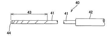
- FIG. 4 shows another example of an embodiment of a bougie used in the present invention.
- a bougie 40 shown in FIG. 4 includes a rod-like body 41 and a grip portion 42 connected to the proximal end thereof, and a hemispherical distal end portion 44 is provided at the distal end of the rod-like body 41.
- the example of the embodiment shown in FIG. 4 is different from the example of the embodiment shown in FIG. 3 in the configuration of the spiral cut in the cylindrical coil structure, but other configurations (other than the tip portion, the gripping portion, and the cylindrical coil structure).
- the configuration of the rod-like body is the same. Therefore, below, the structure of the cylindrical coil structure 43 is demonstrated and description of another structure is abbreviate
- the pitch interval of the spiral cuts is gradually increased from the distal end side to the proximal end side of the rod-like body 41. Therefore, in this embodiment, the cylindrical coil structure 43 constituting the highly flexible portion has higher flexibility on the distal end side than the proximal end side, and is directed from the proximal end side toward the distal end side. Accordingly, the flexibility is gradually increased. Thereby, as described above, the possibility that the bougie 40 breaks through the tube 1 and damages the inner wall of the lacrimal passage or forms a temporary passage is reduced.
- the pitch interval between the spiral cuts may be appropriately determined in consideration of the rigidity and flexibility of the rod-like body 41, and may be set to, for example, 0.05 to 2 mm.
- the change in the pitch interval may be gradually increased from the distal end side to the proximal end side within this range.
- the bougie used in the present invention is suitable as an attached bougie for an intra lacrimal intubation device, but can also be used as a bougie alone without being used together with a lacrimal tube.
- Example 1 A tube having an outer diameter of 1.0 mm / inner diameter of 0.5 mm was formed using a synthetic resin having a weight ratio of SIBSTAR (registered trademark) 102T and Tecoflex EG85A of 10/90, and the tip was made a blind end. This tube was used as a model sample for one of the lacrimal duct tubes. A constant spiral cut with a width of 0.04 mm and a pitch interval of 0.25 mm is formed by laser cutting in the tip of a stainless steel cylinder with an outer diameter of 0.47 mm / inner diameter of 0.14 mm, from the tip to 8 mm. did. The cut was formed so as to penetrate the inside and outside of the cylinder.
- SIBSTAR registered trademark
- Tecoflex EG85A 10/90
- a gripping part was joined to the base end portion of the stainless steel cylinder to create a bougie.
- This bougie was inserted into a tube made as a model sample, and a test sample of an intra lacrimal intubation device was obtained.
- Example 2 As shown in FIG. 5, as a spiral cut portion 52 formed in a stainless steel cylinder 51, the pitch interval 53 at the tip of the cylinder 51 is set to 0.25 mm, and the pitch interval 54 at the base end is set to 0.50 mm.
- a test sample of the bougie 50 and lacrimal canal intubation device was obtained in the same manner as in Example 1 except that the pitch interval was gradually increased from the distal end to the proximal end so that the length (total length of the cut portion) was about 8 mm. It was.
- Comparative Example 1 A commercially available lacrimal intubation device (manufactured by Kaneka Corporation, product name NS tube) was used as a test sample.
- this comparative example 1 has the same configuration as that of the example 1 except that the bougie is not a cylinder but a columnar bar and that no cut is made.
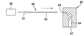
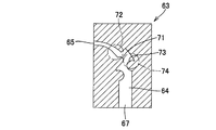
- a digital force gauge 66 shows the load when the test samples of the above-described examples and comparative examples are inserted through the simulated lacrimal passage 64 having the entrance 65 and the exit 67 formed inside the test jig 63 shown in FIGS. It was measured by.
- the measurement method will be specifically described with reference to FIGS. 6 and 7 as follows.
- a digital force gauge 66 is disposed on the base end side of the test sample 60 in which the bougie 61 manufactured as described above is inserted into the lumen portion of the tube 62, and the test sample 60 is detected by the digital force gauge 66. 6 is moved in the direction of the arrow in FIG.
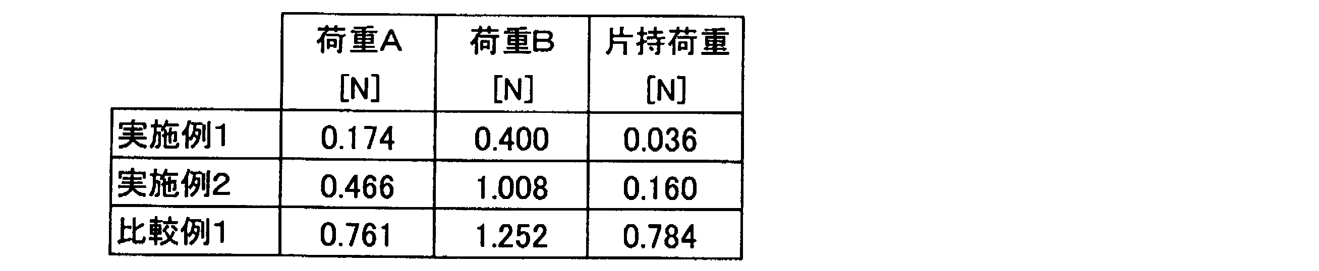
- the loads A and B and the cantilever load in Example 1 are significantly lower than those in Comparative Example 1.
- the loads A and B and the cantilever load in Example 2 are higher than those in Example 1, but lower than those in Comparative Example 1.
- the bougie resists the simulated lacrimal passage by providing a predetermined spiral cut with a constant pitch interval, in which the tip of the bougie is a relatively flexible portion. You can see that it has progressed.
- the test sample of Example 2 which has a spiral notch with the pitch interval gradually widening from the distal end side toward the proximal end side, may be less likely to pass through the simulated lacrimal passage compared to Example 1.
- the pushing force can be transmitted to the tip side more easily than in the first embodiment.
- the tip portion is more flexible than the conventional one in Comparative Example 1.
Landscapes
- Health & Medical Sciences (AREA)
- Ophthalmology & Optometry (AREA)
- Biomedical Technology (AREA)
- Nuclear Medicine, Radiotherapy & Molecular Imaging (AREA)
- Surgery (AREA)
- Engineering & Computer Science (AREA)
- Plastic & Reconstructive Surgery (AREA)
- Heart & Thoracic Surgery (AREA)
- Vascular Medicine (AREA)
- Life Sciences & Earth Sciences (AREA)
- Animal Behavior & Ethology (AREA)
- General Health & Medical Sciences (AREA)
- Public Health (AREA)
- Veterinary Medicine (AREA)
- Prostheses (AREA)
Description
本発明は、涙道閉塞治療に用いる涙道内挿管器具に関する。
流涙症やドライアイを誘発する涙道閉塞の治療法には、(a)涙嚢鼻腔吻合術、(b)涙小管形成術、(c)鼻涙管形成術、(d)涙丘移動術、(e)涙道チューブ挿管術などがある。
これらのうち、上記(a)~(d)などの治療法では顔に切開を入れたり骨に穴をあけたりして涙道閉塞部を貫通させるため、治療効果は高い反面、侵襲度は高いという問題がある。そのため、これらの手技は最終手段として行われることが多い。
一方、上記(e)の治療方法は、上記(a)~(d)などの治療法に比べて、手技が容易であり、かつ侵襲度が低いため、第一治療として選択され、広く実施されている。
(e)涙道チューブ挿管術を簡単に説明すると次のようなものである。
先ず、必要により、ブジーと呼ばれる棒状の器具を閉塞している涙道に挿入し、閉塞部位を予め開通する。次に、付属ブジーが挿入された涙道チューブ(涙道内挿管器具)を用い、付属ブジーを操作して涙道チューブを涙道内へと誘導し、閉塞部位を超えるようにして涙道チューブが挿通される。その後、付属ブジーのみを抜き取り、涙道チューブは留置させ、涙道が広がった状態で安定したころでチューブを抜き取る。
涙道チューブ挿管術は、このような処置を行うことにより、涙道の閉塞部位を完全に開放し、再び正常な涙道機能を確保することができる。
また、この涙道チューブ挿管術では、上記のように、付属ブジーと涙道チューブとを備える涙道内挿管器具が用いられる。そして、涙道チューブとしては、ヌンチャク型涙道チューブと称されるものが広く普及している(特許文献1参照)。このヌンチャク型涙道チューブは、チューブの中央部分が細く柔らかいチューブやロッドで形成され、その両側が中央部より太く硬いチューブで形成され、この太いチューブのそれぞれに設けられた切れ目から一対の付属ブジーが挿入された構造を有するものである。
先ず、必要により、ブジーと呼ばれる棒状の器具を閉塞している涙道に挿入し、閉塞部位を予め開通する。次に、付属ブジーが挿入された涙道チューブ(涙道内挿管器具)を用い、付属ブジーを操作して涙道チューブを涙道内へと誘導し、閉塞部位を超えるようにして涙道チューブが挿通される。その後、付属ブジーのみを抜き取り、涙道チューブは留置させ、涙道が広がった状態で安定したころでチューブを抜き取る。
涙道チューブ挿管術は、このような処置を行うことにより、涙道の閉塞部位を完全に開放し、再び正常な涙道機能を確保することができる。
また、この涙道チューブ挿管術では、上記のように、付属ブジーと涙道チューブとを備える涙道内挿管器具が用いられる。そして、涙道チューブとしては、ヌンチャク型涙道チューブと称されるものが広く普及している(特許文献1参照)。このヌンチャク型涙道チューブは、チューブの中央部分が細く柔らかいチューブやロッドで形成され、その両側が中央部より太く硬いチューブで形成され、この太いチューブのそれぞれに設けられた切れ目から一対の付属ブジーが挿入された構造を有するものである。
(e)の治療法は、上述のように、(a)~(d)などの治療法に比べて、手技が容易で侵襲度が低い点で有効な治療法である。しかしながら、涙道チューブを涙道内へと誘導する際には、盲目的に行われることが一般的である。そのため、術者は慎重を期して施術を行うものの、涙道の湾曲した部位や隆起した部位に挿管する際に人為的なミスが起きることがあるという問題がある。例えば、付属ブジーが涙道チューブを突き破って涙道を傷つけたり、さらに重篤な場合には、正常な涙道以外に穴(仮道)を開けたりすることがある。従って、(e)の治療法であっても、治療成績は必ずしも良好とはいえなかった。また、術者の経験、解剖学的知識及び操作時の感覚に依存するところが大きく、経験等の少ない術者であってもより安全に涙道チューブ挿管術を行うことが可能な涙道内挿管器具が求められていた。
そこで、このような問題を解決するため、例えば、涙道内挿管器具のブジーを涙道チューブの先端部まで挿入せずに、涙道チューブ先端部から3~10mm程度ブジーが配されない部分を形成し、涙道チューブ先端部を遊ぶようにさせた涙道内挿管器具が提案されている。確かに、このようにブジーを配置することで、涙道チューブの先端部はブジーが存在しないためブジーによる強度の高い部分はなくなるものの、涙道チューブのみの先端部分を閉塞部位に通過させる必要があるため、予め閉塞部位がある程度開通していたとしても、閉塞部位を通過させるための強度が低下し、涙道チューブの挿通性に問題が生じる可能性がある。また、涙道チューブを閉塞部位に挿通する際に、無理に力が入った場合は、結局、ブジーが涙道チューブ内を先端側に相対的に移動したりして、チューブを突き破って涙道を傷つけたり、仮道を形成する可能性がある。
また、その他の対応としては、ヌンチャク型涙道チューブの両端に先端開放部を有するとともに、ブジー先端が先端開放部の近傍より突出しないように規制するストッパーをブジーに設けた涙道内挿管器具(特許文献2参照)、ブジー先端がチューブの所定位置にあることを目視で確認できるマークをブジーとチューブに設けた涙道内挿管器具(特許文献3参照)、超弾性合金ワイヤーにより構成されているワイヤー部を有する涙道治療用ブジーが差し込まれたチューブ(特許文献4参照)などが提案されている。
特許文献2に記載の涙道内挿管器具では、ブジーの先端が直接涙道の壁面に当接したことを術者が直接感知することができることから、涙道壁面をブジーの先端で傷つける可能性が少なくなり、また、ストッパーにより、ブジー先端が露出しても、ブジーがチューブから不用意に突出することはないなどとされている。
特許文献3に記載の涙道内挿管器具では、涙道チューブと付属ブジーに相対的位置関係を目視できるマークを設けることで、例えば先端開放部を有する涙道チューブにブジーを挿入して涙道に涙道チューブを挿管する際に、涙道内壁と涙道チューブとの摩擦によってチューブがブジーに沿ってたくし上がったことを、術者が目視により確認することができるため、チューブがたくし上がった状態で涙道内への挿入を続けた場合に涙道壁面を傷付けることが少なくなるとされている。
特許文献4に記載のブジーでは、ワイヤー部が超弾性合金ワイヤーにより構成されることで、ワイヤー部が超弾性効果により比較的大きな歪量まで弾性的に変形し(曲がり)、また一端曲がっても曲がり癖が生ずることなく形状が回復するため、涙道に沿って比較的容易に曲がり、作業性が向上し、涙道を傷める可能性が低減するとされている。
特許文献3に記載の涙道内挿管器具では、涙道チューブと付属ブジーに相対的位置関係を目視できるマークを設けることで、例えば先端開放部を有する涙道チューブにブジーを挿入して涙道に涙道チューブを挿管する際に、涙道内壁と涙道チューブとの摩擦によってチューブがブジーに沿ってたくし上がったことを、術者が目視により確認することができるため、チューブがたくし上がった状態で涙道内への挿入を続けた場合に涙道壁面を傷付けることが少なくなるとされている。
特許文献4に記載のブジーでは、ワイヤー部が超弾性合金ワイヤーにより構成されることで、ワイヤー部が超弾性効果により比較的大きな歪量まで弾性的に変形し(曲がり)、また一端曲がっても曲がり癖が生ずることなく形状が回復するため、涙道に沿って比較的容易に曲がり、作業性が向上し、涙道を傷める可能性が低減するとされている。
しかしながら、特許文献2、3に記載の涙道内挿管器具では、ブジーの先端が涙道の壁面に当接したこと、チューブがたくし上がったことを術者が直接感知できるとしても、閉塞部位に挿通するために力をかける必要があった場合には、不意に涙道の内壁に当接して涙道を傷める可能性がある。また、特許文献4に記載のブジーをチューブに挿入して使用した場合は、ブジーが超弾性を有するワイヤー部より構成されているため、閉塞部位を挿通するための剛性の面では、必ずしも十分とはいえず、閉塞部位へ挿通する際のブジーの操作性が低下する可能性がある。そのため、力を必要以上にかけることになり、却って涙道を傷める可能性がある。
また、例えば特許文献2に記載の涙道内挿管器具では、涙道チューブの先端に先端開放部を有することから、ブジーの代わりに内視鏡を用いることで、盲目的ではない方法で涙道チューブを挿入することも可能であるとされている。内視鏡をブジーとして用いれば、モニターで涙道内を把握しつつ挿管は可能なものの、モニター画像と、ブジーと涙道チューブの状態との双方を確認しつつ操作を行う必要があるうえ、内視鏡は長尺であることから、ブジーの扱いが困難になり、作業効率は却って低下する可能性がある。そのため、現在のところ、内視鏡を用いず盲目的に涙道チューブ挿管術が行われることが多い。
以上のことから、涙道チューブ挿管術を盲目的に行っても、ブジーの操作性を確保しつつ、涙道を損傷する可能性が低減され、より安全に涙道への挿管が可能な涙道内挿管器具の開発が求められている。
上記のような事情に鑑み、本発明の目的とするところは、従来の付属ブジー(ブジー)と同様の操作性を保持しつつ、盲目的な操作でも涙道を傷つけたり仮道を形成したりする可能性がより低減された涙道内挿管器具を提供することにある。
発明者らは、かかる課題を解決すべく鋭意検討を行った結果、涙道内挿管器具において、その構成部材であるブジーの所定位置に可撓性を付与することにより、操作性を損なうことなく、盲目的に操作を行っても、涙道を傷付けたり仮道を形成したりする可能性が低減されることを見出し、本発明を完成するに至った。
即ち、本発明の要旨は以下の通りである。
〔1〕涙道内に留置されるチューブと、該チューブの内腔部に着脱可能に挿入されるブジーとを備える涙道内挿管器具であって、前記ブジーは、その先端側に前記チューブの内腔部に配される部分を、その基端側に前記チューブの外側に配される部分を有し、前記チューブの内腔部に配される部分が、前記チューブの外側に配される部分より可撓性の高い部分を有することを特徴とする涙道内挿管器具。
〔2〕前記可撓性の高い部分が、前記ブジーの先端部分に配される前記〔1〕記載の涙道内挿管器具。
〔3〕前記可撓性の高い部分は、さらに、その基端側より先端側において可撓性が高い前記〔1〕又は〔2〕記載の涙道内挿管器具。
〔4〕前記可撓性の高い部分が、円筒コイル構造を有する前記〔1〕~〔3〕の何れかに記載の涙道内挿管器具。
〔5〕前記可撓性の高い部分が、樹脂又は弾性金属よりなる前記〔1〕~〔4〕の何れかに記載の涙道内挿管器具。
〔1〕涙道内に留置されるチューブと、該チューブの内腔部に着脱可能に挿入されるブジーとを備える涙道内挿管器具であって、前記ブジーは、その先端側に前記チューブの内腔部に配される部分を、その基端側に前記チューブの外側に配される部分を有し、前記チューブの内腔部に配される部分が、前記チューブの外側に配される部分より可撓性の高い部分を有することを特徴とする涙道内挿管器具。
〔2〕前記可撓性の高い部分が、前記ブジーの先端部分に配される前記〔1〕記載の涙道内挿管器具。
〔3〕前記可撓性の高い部分は、さらに、その基端側より先端側において可撓性が高い前記〔1〕又は〔2〕記載の涙道内挿管器具。
〔4〕前記可撓性の高い部分が、円筒コイル構造を有する前記〔1〕~〔3〕の何れかに記載の涙道内挿管器具。
〔5〕前記可撓性の高い部分が、樹脂又は弾性金属よりなる前記〔1〕~〔4〕の何れかに記載の涙道内挿管器具。
本発明によれば、従来の付属ブジー(ブジー)と同様の操作性を保持しつつ、盲目的な操作でも涙道を傷つけたり仮道を形成したりする可能性が低減された涙道内挿管器具を提供することができる。
以下に、本発明の実施形態を添付図面に基づき説明する。
本発明の涙道内挿管器具は、涙道内に留置されるチューブ(涙道チューブとも称する。)と、該チューブの内腔部に着脱可能に挿入されるブジー(付属ブジーとも称する。)とを備える。そこで、先ず、このチューブが留置される涙道の構造を簡単に説明する。
図2は、涙道の解剖学的な構造を示した図である。本発明でいう涙道とは、図2に示すように、上/下涙点(21/22)、上/下涙小管(23/24)、総涙小管(25)、涙嚢(26)、鼻涙管(27)、鼻腔管(図示せず)、Hasner’s valve(図示せず)から構成され、涙腺(図示せず)から産出された涙液を眼表面から下鼻道(28)へと導く管(眼球付属器)である。尚、上涙点(21)から、上涙小管(23)、総涙小管(25)を経て下鼻道(28)へと導く管を上涙道といい、下涙点(22)から下涙小管(24)、総涙小管(25)を経て下鼻道(28)へと導く管を下涙道という。
図2は、涙道の解剖学的な構造を示した図である。本発明でいう涙道とは、図2に示すように、上/下涙点(21/22)、上/下涙小管(23/24)、総涙小管(25)、涙嚢(26)、鼻涙管(27)、鼻腔管(図示せず)、Hasner’s valve(図示せず)から構成され、涙腺(図示せず)から産出された涙液を眼表面から下鼻道(28)へと導く管(眼球付属器)である。尚、上涙点(21)から、上涙小管(23)、総涙小管(25)を経て下鼻道(28)へと導く管を上涙道といい、下涙点(22)から下涙小管(24)、総涙小管(25)を経て下鼻道(28)へと導く管を下涙道という。
図1は、本発明に係る涙道内挿管器具の一実施形態を示す平面図である。図1に示すように、本実施形態における涙道内挿管器具10は、涙道内に留置されるチューブ1と、チューブ1の内腔部に着脱可能に挿入される一対のブジー2a、2bとを備える。
チューブ1の構造は特に限定はないが、涙道内に留置される一体のチューブを備えたものが好ましい。ここで「一体の」とは、上/下涙道のそれぞれに挿入される2本のチューブが、全体として1本となっていることを意味する。
図1に示す実施形態の例では、チューブ1は、略中央部分に、涙点、涙小管、総涙小管、涙嚢に留置される部位となる、筒形状またはロッド形状の中央部4、中央部4の一端に連設され、涙嚢、鼻涙管、Hasner’s valve、下鼻道に留置される部位となる、筒形状の第1筒状部5a、中央部4の他端に連設され、涙嚢、鼻涙管、Hasner’s valve、下鼻道に留置される部位となる、筒形状の第2筒状部5bから構成され、一体のチューブとなっている。また、中央部4は、第1筒状部5aおよび第2筒状部5bよりも細く、柔軟に形成されており、いわゆるヌンチャク型涙道チューブと称されるものである。また、中央部4の柔軟性の程度は、筒状部5a、5bよりも柔軟であれば特に限定はないが、チューブ1の長さ方向の中心点で支持して持ち上げると逆U字型となる程度に、中央部が柔軟であるものが好ましい。チューブ1の柔軟性は、後述する材質の種類や寸法などにより調整することが可能である。
また、涙道内に留置される一体のチューブの他の例としては、全長に亘り略一定の内外径を有するものであってもよいし、実用上差し支えない範囲で、図1の実施形態における中央部4に相当する部分を、その両端の筒状部5a、5bに相当する部分より外径を大きくしてもよい。
本実施形態では、第1筒状部5aの第1末端6aおよび第2筒状部5bの第2末端6bは盲端となっており、閉塞部位への挿入を容易にするため、その先端はとがった形状となっている。もっとも、筒状部5a、5bの少なくとも一方の末端は、盲端とするのではなく、開口部を設けてもよい。これにより、通水検査を行うことが可能となる。また、必要によりブジーを抜去して内視鏡を挿入し、涙道内を確認することも可能となる。
また、第1末端6aを含む先端部分は、第2末端6bを含む先端部分と術者が見分けやすいように、着色されている。さらに、第1筒状部5aの第1末端6aから所定位置に2つのマーク9aが付されており、挿入深度を術者が視認できるようになっている。第2筒状部5bにも、同様に、マーク9bが付されている。加えて、中央部4には、チューブ1の挿入位置や留置位置の確認を容易にするため、チューブ1の略中央となる位置に中点を示すマーク3を設けている。これらの着色やマークは、必要により適宜設ければよい。
また、第1末端6aを含む先端部分は、第2末端6bを含む先端部分と術者が見分けやすいように、着色されている。さらに、第1筒状部5aの第1末端6aから所定位置に2つのマーク9aが付されており、挿入深度を術者が視認できるようになっている。第2筒状部5bにも、同様に、マーク9bが付されている。加えて、中央部4には、チューブ1の挿入位置や留置位置の確認を容易にするため、チューブ1の略中央となる位置に中点を示すマーク3を設けている。これらの着色やマークは、必要により適宜設ければよい。
本実施形態では、第1筒状部5aおよび第2筒状部5bの中央部4の近傍の側壁に、それぞれブジー2aおよび2bを挿入するための開口部7aおよび7bが配され、開口部7aおよび7bを介して、第1ブジー2aおよび第2ブジー2bが、それぞれ第1筒状部5aおよび第2筒状部5bの内腔部に挿通されている。開口部7a、7bの形状は、特に限定はないが、側壁に切れ目を設けたものでも良いし、円や楕円などの小孔であってもよい。図1には、側壁に切れ目を設けた例を示している。
チューブ1の材質は、涙道に挿通かつ留置可能な適度な柔軟性を有し、生体適合性があるものであれば、特に限定はなく、例えばシリコーン、ポリウレタン、イソブチレン系共重合体、およびこれらのアロイ等を含む樹脂組成物が挙げられるが、これらに限定されない。
本発明では、上記アロイとしては特に限定はないが、例えば、熱可塑性ポリウレタン系樹脂とイソブチレン系共重合体のアロイを用いる場合、前記イソブチレン系共重合体(A)と、熱可塑性ポリウレタン系樹脂(B)との割合を調整することで、チューブの硬さを調整できる。熱可塑性ポリウレタン系樹脂(B)の割合を大きく設定するほど、チューブの硬度を大きくすることができる。尚、抗血栓性、表面滑り性、柔軟性の観点から考えると、イソブチレン系共重合体(A)が1重量%以上含まれていることが好ましい(即ち、イソブチレン系共重合体(A)と熱可塑性ポリウレタン系樹脂(B)の割合が、重量比で(A)/(B)=1/99~99/1)。中でも、耐摩耗性の観点から考えると、イソブチレン系共重合体(A)と熱可塑性ポリウレタン系樹脂(B)の割合が、重量比で(A)/(B)=1/99~70/30であることが好ましい。特に、圧縮応力の観点から考えると、イソブチレン系共重合体(A)と熱可塑性ポリウレタン系樹脂(B)の割合が、重量比で(A)/(B)=1/99~50/50であることが好ましく、1/99~20/80であることがより好ましい。本発明に用いられるチューブ用の樹脂組成物としては、イソブチレン系共重合体(A)と熱可塑性ポリウレタン系樹脂(B)のみからなるものでもよいし、他の成分を混合してもよいが、耐摩耗性の観点からは、イソブチレン系共重合体(A)と熱可塑性ポリウレタン系樹脂(B)のみからなるものが好ましい。
イソブチレン系共重合体(A)としては、特に限定はなく、例えば、スチレン―イソブチレン―スチレンブロック共重合体(以下、SIBSという。)が挙げられるが、これに限定されるわけではない。また、SIBSとしては、例えば、株式会社カネカ製「SIBSTAR(登録商標)102T」が挙げられる。
熱可塑性ポリウレタン系樹脂(B)(以下、TPUという。)としては、特に限定はなく、例えば、エーテル系芳香環式ポリウレタン、エーテル系脂環式ポリウレタン、ポリカーボネート系ポリウレタン等が挙げられるが、これらに限定されるわけではない。また、エーテル系芳香環式ポリウレタンとしては、例えば、日本ミラクトラン社製「ミラクトラン(登録商標)E385PNAT」、ノヴェオン社製「テコタンTT1074A」などが、エーテル系脂環式ポリウレタンとしては、例えば、ノヴェオン社製「テコフレックスEG100A」、「テコフレックスEG85A」などが、ポリカーボネート系ポリウレタンとしては、例えば、ノヴェオン社製「カルボタンPC3575A」などが挙げられる。
熱可塑性ポリウレタン系樹脂(B)(以下、TPUという。)としては、特に限定はなく、例えば、エーテル系芳香環式ポリウレタン、エーテル系脂環式ポリウレタン、ポリカーボネート系ポリウレタン等が挙げられるが、これらに限定されるわけではない。また、エーテル系芳香環式ポリウレタンとしては、例えば、日本ミラクトラン社製「ミラクトラン(登録商標)E385PNAT」、ノヴェオン社製「テコタンTT1074A」などが、エーテル系脂環式ポリウレタンとしては、例えば、ノヴェオン社製「テコフレックスEG100A」、「テコフレックスEG85A」などが、ポリカーボネート系ポリウレタンとしては、例えば、ノヴェオン社製「カルボタンPC3575A」などが挙げられる。
本発明では、涙道内挿管器具の涙道への挿入性を高めるために、チューブ1の外側に親水性のコーティングを設けてもよい(図示せず)。当該コーティングにより、血液と接触した際に潤滑性が発現し、挿入時の抵抗が低減される。親水性のコーティングの種類は特に限定されず、ポリ(2-ヒドロキシエチルメタクリレート)、ポリアクリルアミド、ポリビニルピロリドン、ポリエチレングリコール等の親水性ポリマー、又はこれらのブレンド等が好適に使用される。
チューブ1の筒状部5a、5bの大きさについては、涙道に挿入可能な外径とブジー2a、2bを挿入可能な内径とを有していれば特に限定はない。一般的には外径を概ね0.9~1.2mm、内径を概ね0.5~0.7mmとすると良い。チューブ1全体の長さは、体型、病変状態などを考慮して、それらに基づく涙道の構造に応じて、中央部4、筒状部5a、5bの長さを適宜決定すれば良い。
本発明の涙道内挿管器具で用いるブジーは、涙道内に留置されるチューブの内腔部に着脱可能に挿入され、その先端側に前記チューブの内腔部に配される部分を、その基端側に前記チューブの外側に配される部分を有し、前記チューブの内腔部に配される部分が、前記チューブの外側に配される部分より可撓性の高い部分を有する。
このように、チューブの内腔部に配される部分が、チューブの外側に配される部分より可撓性の高い部分を有することで、閉塞部位を挿通させる際の術者による押込み力をチューブの遠位側に伝え、涙道内挿管器具に使用される従来のブジーと同様の操作性は保持したままで、ブジーの可撓性の高い部分により、たとえチューブまたはブジーの先端が涙道の内壁に突き当った場合でも、効果的に押込み力を逃がして、涙道の内壁の損傷や、仮道が形成される可能性を、従来の涙道内挿管器具よりも低減することが可能となる。
図1に示す実施形態では、ブジー2a、2bは、それぞれ、チューブ1の開口部7a、7bから、チューブ1の内腔部に挿入されている。ブジー2a、2bは、棒状体11a、11bと、棒状体11a、11bの基端側に配された把持部8a、8bとを有し、ブジー2a、2bの先端側にチューブ1(筒状部5a、5b)の内腔部に配される部分13a、13b(破線部分)と、その基端側にチューブ1の外側に配される部分12a、12bを備える。もっとも、ブジー2a、2bはチューブ1に対して着脱可能であるため、チューブ1の内腔部に配される部分の位置は変動するが、涙道内へ挿管する際の状態の配置を基準とする。尚、図1の実施形態では、ブジー2a、2bの先端が、チューブ1(筒状部5a、5b)の内腔部の先端部分に突き当てに配された状態を示したものである。
本発明で使用するブジーにおいて、上記の可撓性の高い部分の位置は特に限定はなく、ブジーのうち、チューブ内に配され得る部分に設ければよいが、涙道の壁面へ突き当った場合の壁面の損傷や仮道の形成の可能性の低減、涙道内の湾曲部や隆起部での通過性の向上の観点からは、可撓性の高い部分は、ブジーの先端部分に設けることが好ましい。
本発明で使用するブジーにおいて、上記の可撓性の高い部分を設ける手段としては、特に限定はない。例えば、円筒コイル構造を採用したり、使用する材質自体の物性を利用したり、ブジーの太さの変化を利用したり、これらを組合せることで実現することが可能である。
円筒コイル構造としては、例えば、素線をコイル状に巻き回して略円筒状に形成したもの、円筒に螺旋状の切り込みを施したもの等が挙げられる。
素線をコイル状に巻き回して略円筒状に形成したものにおいて使用する素線としては、医療分野において広く使用されるガイドワイヤと同様の材質、構造を採用することが可能である。例えば、素線の断面形状は、円形、楕円形、平板状などを採用することが可能であり、素線の巻き状態は、密巻きでも良いし、素線間に隙間が形成されたピッチ巻きでもよい。さらに、素線間の隙間は、一定でも良いし、任意に変化させても良い。
円筒に螺旋状の切り込みを施したものは、金属や樹脂の筒状体に、レーザーなどで螺旋状の切り込みを形成することで得ることができる、切り込みは、筒状体の外周面から内周面に亘り貫通したものでも良いし、筒状体の表面から所定厚さの位置まで形成したもの(貫通していないもの)でも良い。また、螺旋状の切り込みのピッチ間隔は、同一でも良いし、任意に変化させても良い。
素線をコイル状に巻き回して略円筒状に形成したものにおいて使用する素線としては、医療分野において広く使用されるガイドワイヤと同様の材質、構造を採用することが可能である。例えば、素線の断面形状は、円形、楕円形、平板状などを採用することが可能であり、素線の巻き状態は、密巻きでも良いし、素線間に隙間が形成されたピッチ巻きでもよい。さらに、素線間の隙間は、一定でも良いし、任意に変化させても良い。
円筒に螺旋状の切り込みを施したものは、金属や樹脂の筒状体に、レーザーなどで螺旋状の切り込みを形成することで得ることができる、切り込みは、筒状体の外周面から内周面に亘り貫通したものでも良いし、筒状体の表面から所定厚さの位置まで形成したもの(貫通していないもの)でも良い。また、螺旋状の切り込みのピッチ間隔は、同一でも良いし、任意に変化させても良い。
使用する材質自体の物性を利用する場合は、例えば、可撓性を高くする部分に、それと隣接する部分より、弾性の高い材質を配することで実現することができる。例えば、ステンレスなどの剛性の高い金属と、超高弾性金属(例えば、ニッケルチタン系合金など)とを組み合わせたり、剛性の高い金属と天然または合成樹脂とを組合せたり、剛性の高い樹脂と低い樹脂とを組合せたりして、ブジーを形成するとよい。この場合は、各材質の接合は、材質の特性に基づき、溶接、接着、溶着、または、物理的ないし構造的な接合などを採用することができる。
ブジーの太さの変化を利用する場合は、同一材質の棒状体の所定の位置に、棒状体の軸長さ方向の所定の範囲にわたって、棒状体の軸方向に対して垂直な方向の幅が小さくなる部分を設けることで実現することができる。この部分の形状は、例えば、ブジーの外表面に所定幅の溝を一周設けたり、螺旋状の溝を設けたりしたものなどが挙げられるが、これらに限定されるわけではない。また、溝の深さ、幅は、一定でも良いし、任意に変化させても良い。また棒状体は、筒状でも良いし、ロッド状でも良い。
また、上記の可撓性の高い部分は、その部分全体が同様の可撓性を有していても良いし、その基端側より先端側において可撓性が高くなっていてもよい。可撓性を付与する構成にもよるが、前者の場合は、後者の場合より、当該可撓性の高い部分の可撓性がより大きくなる傾向にある。従って、涙道内の構造や、閉塞部位の状況に応じて、可撓性の高い部分の構成を適宜選択するとよい。また、上記の後者の場合、可撓性の高い部分の構成としては、当該部分において、基端側から先端側に向かうにしたがい、可撓性が高くなるように構成してもよい。このように構成することで、例えば、可撓性の高い部分が先端部分に配された場合に、術者によりブジーに付与された押込み力が、先端側により効率的に伝達されるため、比較的閉塞部位への挿通に力が必要な場合に、有効である。
ブジーの遠位側の先端部の構造は特に限定はなく、ブジーの遠位側が円筒状である場合、先端が開口していても良いし、半球状などになるような部材を配しても良い。また、ブジーの遠位側がロッド状である場合は、先端を丸め加工などを施して、先端に丸みを付与した構造とするとよい。
図3は、本発明で使用するブジーの実施形態の一例を示したものである。本実施形態の例では、ブジー30は、棒状体31と、その基端側に連結された把持部32とを備える。また、棒状体31の先端部分には、可撓性の高い部分として、筒状体に螺旋状の切り込みを有する円筒コイル構造33を有している。本例では、円筒コイル構造33は、螺旋状の切り込みのピッチ間隔が一定となっている。また、切り込みは、棒状体31の外周と内周とが貫通するように設けられている。円筒コイル構造33は、棒状体31を円筒状として、その先端側をレーザーカットにより、螺旋状に切り込みを入れることで形成することができる。他の方法としては、円筒コイル構造33を形成し、ロッド状の棒状体の遠側端部に溶接などにより連結してもよい。また、本実施形態では、先端部に半球状の先端部34を配しているが、配さない構成であっても良い。棒状体31と把持部32とは、定法に従って連結すればよい。また、棒状体31の材質は、樹脂、金属など適宜選択することができる。金属を用いる場合、円筒コイル構造33の可撓性をより高くする観点から、円筒コイル構造33に高弾性金属を採用し、それ以外の部分に他の剛性の高い金属を採用しても良い。もっとも、棒状体31全体をステンレスなどの剛性の高い金属で構成しても良い。
円筒コイル構造33の軸方向長さは、特に限定はないが、本発明の作用効果を好適に奏する観点からは、ブジー30の最先端(先端部34を含む)から3~20mmが好ましく、5~10mmがより好ましい。また、螺旋状の切り込みのピッチ間隔は、ブジーの可撓性の程度と剛性とを考慮して適宜選択すればよい。尚、切り込みのピッチ間隔とは、軸方向の同一軸線上の隣接する切り込みの略中央部間の距離を意味する。また、螺旋状の切り込みの幅は、同じくブジーの可撓性の程度とブジーの剛性を考慮して適宜選択すればよい。棒状体31の外径は、チューブ1の内腔部に挿入可能で、容易には脱落しない程度であれば、特に限定はない。
図4は、本発明で使用するブジーの実施形態の他の例を示したものである。図4に示すブジー40は、棒状体41と、その基端側に連結された把持部42とを備え、棒状体41の先端には半球状の先端部44を備える。図4に示す実施形態の例は、図3に示す実施形態の例とは、円筒コイル構造における螺旋状の切り込みの構成が異なるが、他の構成(先端部、把持部、円筒コイル構造以外の棒状体の構成など)は同じである。従って、以下では、円筒コイル構造43の構成について説明し、他の構成の説明は省略する。
図4に示す実施形態の例における円筒コイル構造43は、図3の例とは異なり、螺旋状の切り込みのピッチ間隔が、棒状体41の先端側から基端側にかけて順次大きくなっている。そのため、本実施形態では、可撓性の高い部分を構成する円筒コイル構造43は、その基端側より先端側において可撓性が高くなっており、かつ、基端側から先端側に向かうにしたがい、可撓性が順次高くなっている。これにより、前述のように、ブジー40がチューブ1を突き破って、涙道内壁を損傷したり、仮道を形成したりする可能性が低減され、ブジーを涙道内腔の空洞部に挿管する際にスムーズに挿管できるだけでなく、涙道の閉塞部位にブジーを挿管する際に比較的大きな力が必要な場合に、より剛性を確保することができる。本実施形態の例においては、螺旋状の切り込みのピッチ間隔は、棒状体41の剛性と可撓性を考慮して、適宜決定すれば良く、例えば、0.05~2mmとすることができ、そのピッチ間隔の変化も、この範囲で、先端側から基端側にかけて順次大きくすればよい。
以上のように、本発明で用いるブジーは、涙道内挿管器具の付属ブジーとして好適であるが、涙道チューブと併用することなく、ブジー単体として使用することも可能である。
以下、実施例に基づき、本発明の実施形態をより具体的に説明するが、本発明がこれらに限定されるものではない。
(実施例1)
SIBSTAR(登録商標)102TとテコフレックスEG85Aの重量比が10/90である合成樹脂を用いて、外径1.0mm/内径0.5mmのチューブを成形し、先端を盲端とした。本チューブを涙道チューブの一方のモデルサンプルとして使用した。
外径0.47mm/内径0.14mmのステンレス製の円筒の先端部分、先端から8mmまでの範囲に、レーザーカットにより、幅0.04mm、ピッチ間隔0.25mmで一定の螺旋状の切り込みを形成した。切り込みは、円筒の内外を貫通するように形成した。その後、ステンレス製の円筒の基端部分に把持部を接合し、ブジーを作成した。
このブジーを、モデルサンプルとして作成したチューブ内に挿入し、涙道内挿管器具の試験サンプルを得た。
SIBSTAR(登録商標)102TとテコフレックスEG85Aの重量比が10/90である合成樹脂を用いて、外径1.0mm/内径0.5mmのチューブを成形し、先端を盲端とした。本チューブを涙道チューブの一方のモデルサンプルとして使用した。
外径0.47mm/内径0.14mmのステンレス製の円筒の先端部分、先端から8mmまでの範囲に、レーザーカットにより、幅0.04mm、ピッチ間隔0.25mmで一定の螺旋状の切り込みを形成した。切り込みは、円筒の内外を貫通するように形成した。その後、ステンレス製の円筒の基端部分に把持部を接合し、ブジーを作成した。
このブジーを、モデルサンプルとして作成したチューブ内に挿入し、涙道内挿管器具の試験サンプルを得た。
(実施例2)
図5に示すように、ステンレス製の円筒51に形成される螺旋状の切り込み部分52として、円筒51の先端のピッチ間隔53を0.25mm、基端のピッチ間隔54を0.50mmとし、螺旋長(切り込み部分の全長)が約8mmとなるように、先端から基端にかけて、ピッチ間隔を漸次大きくしたこと以外は、実施例1と同様にしてブジー50、涙道内挿管器具の試験サンプルを得た。
図5に示すように、ステンレス製の円筒51に形成される螺旋状の切り込み部分52として、円筒51の先端のピッチ間隔53を0.25mm、基端のピッチ間隔54を0.50mmとし、螺旋長(切り込み部分の全長)が約8mmとなるように、先端から基端にかけて、ピッチ間隔を漸次大きくしたこと以外は、実施例1と同様にしてブジー50、涙道内挿管器具の試験サンプルを得た。
(比較例1)
市販の涙道内挿管器具(株式会社カネカ製、製品名N-Sチューブ)を試験サンプルとした。尚、本比較例1は、ブジーが円筒ではなく円柱状の棒であること、及び、切り込みを施さなかったこと以外は、実施例1と同様の構成を有する。
市販の涙道内挿管器具(株式会社カネカ製、製品名N-Sチューブ)を試験サンプルとした。尚、本比較例1は、ブジーが円筒ではなく円柱状の棒であること、及び、切り込みを施さなかったこと以外は、実施例1と同様の構成を有する。
(評価1:模擬涙道内挿通試験)
上記の実施例および比較例の試験サンプルを、図6および7に示す試験治具63の内部に形成された入口65と出口67を有する模擬涙道64に挿通した時の荷重をデジタルフォースゲージ66により測定した。測定方法を図6、7に基づき具体的に説明すると以下のとおりである。
図6に示すように、上記のように作製したブジー61をチューブ62の内腔部に挿入した試験サンプル60の基端側にデジタルフォースゲージ66を配し、デジタルフォースゲージ66にて試験サンプル60の基端を押して、図6中の矢印の方向に2mm/秒の速度で移動させて押込み力を負荷し、試験治具63に設けられた入口65から模擬涙道64内に試験サンプル60を挿通させる(移動距離は約10mmである。)。その際に、図7に示すように模擬涙道64内の突起部1(符号71)が形成されている部分の近傍部(符号72)および突起部2(符号73)が形成されている部分の近傍部(符号74)を通過する際の荷重をそれぞれ荷重Aおよび荷重Bとして測定した。測定結果を表1および図8(a)に示す。
上記の実施例および比較例の試験サンプルを、図6および7に示す試験治具63の内部に形成された入口65と出口67を有する模擬涙道64に挿通した時の荷重をデジタルフォースゲージ66により測定した。測定方法を図6、7に基づき具体的に説明すると以下のとおりである。
図6に示すように、上記のように作製したブジー61をチューブ62の内腔部に挿入した試験サンプル60の基端側にデジタルフォースゲージ66を配し、デジタルフォースゲージ66にて試験サンプル60の基端を押して、図6中の矢印の方向に2mm/秒の速度で移動させて押込み力を負荷し、試験治具63に設けられた入口65から模擬涙道64内に試験サンプル60を挿通させる(移動距離は約10mmである。)。その際に、図7に示すように模擬涙道64内の突起部1(符号71)が形成されている部分の近傍部(符号72)および突起部2(符号73)が形成されている部分の近傍部(符号74)を通過する際の荷重をそれぞれ荷重Aおよび荷重Bとして測定した。測定結果を表1および図8(a)に示す。
(評価2:片持荷重試験)
上記の実施例および比較例の試験サンプルを用い、評価1における試験治具に替えて平板を用い、平板に試験サンプルの先端を突き当て状態にした状態から、デジタルフォースゲージを5mm/分で移動させて押込み力を負荷し、0.9mm押し込んだ時の荷重を片持荷重として測定した。測定結果を表1および図8(b)に示す。
上記の実施例および比較例の試験サンプルを用い、評価1における試験治具に替えて平板を用い、平板に試験サンプルの先端を突き当て状態にした状態から、デジタルフォースゲージを5mm/分で移動させて押込み力を負荷し、0.9mm押し込んだ時の荷重を片持荷重として測定した。測定結果を表1および図8(b)に示す。
表1および図8(a)、(b)に示すように、実施例1の荷重A、B、片持荷重は、比較例1よりも顕著に低い。実施例2の荷重A、B、片持荷重は、実施例1より高いが、比較例1より低い。実施例1の評価1の結果より、ブジーの先端部分が相対的に可撓性の高い部分である、ピッチ間隔が一定の所定の螺旋状の切り込みを備えることにより、ブジーが模擬涙道内を抵抗なく進んでいったことが分かる。また、ピッチ間隔を先端側から基端側に向けて徐々に幅広とした螺旋状の切り込みを備える実施例2の試験サンプルは、実施例1と比較すると模擬涙道内の通過性は低下する可能性はあるものの、押込み力が先端側に伝達することが実施例1より容易であることを示唆するものであり、例えば、比較例1の従来のものと比べて、先端部分の可撓性が高く涙道内壁への損傷の可能性が低減されながらも、閉塞部位の通過が困難な場合に好適である可能性が示唆された。
1 チューブ(ヌンチャク型涙道チューブ)
2a、2b ブジー
3 中点を示すマーク
4 中央部
5a 第1筒状部
5b 第2筒状部
6a 第1末端
6b 第2末端
7a、b 開口部
8a、b 把持部
9a、b マーク
10 涙道内挿管器具
11a、b 棒状体
12a、b チューブ1の外側に配される部分
13a、b チューブ1の内腔部に配される部分
21 上涙点
22 下涙点
23 上涙小管
24 下涙小管
25 総涙小管
26 涙嚢
27 鼻涙管
28 下鼻道
30、40 ブジー
31、41 棒状体
32、42 把持部
33、43 円筒コイル構造
34、44 先端部
50 ブジー
51 円筒
52 螺旋状の切り込み部分
53 円筒51の先端のピッチ間隔
54 円筒51の基端のピッチ間隔
60 試験サンプル
61 ブジー
62 チューブ
63 試験治具
64 模擬涙道
65 入口
66 デジタルフォースゲージ
67 出口
71 突起部1
72 突起部1が形成されている部分の近傍部
73 突起部2
74 突起部2が形成されている部分の近傍部
2a、2b ブジー
3 中点を示すマーク
4 中央部
5a 第1筒状部
5b 第2筒状部
6a 第1末端
6b 第2末端
7a、b 開口部
8a、b 把持部
9a、b マーク
10 涙道内挿管器具
11a、b 棒状体
12a、b チューブ1の外側に配される部分
13a、b チューブ1の内腔部に配される部分
21 上涙点
22 下涙点
23 上涙小管
24 下涙小管
25 総涙小管
26 涙嚢
27 鼻涙管
28 下鼻道
30、40 ブジー
31、41 棒状体
32、42 把持部
33、43 円筒コイル構造
34、44 先端部
50 ブジー
51 円筒
52 螺旋状の切り込み部分
53 円筒51の先端のピッチ間隔
54 円筒51の基端のピッチ間隔
60 試験サンプル
61 ブジー
62 チューブ
63 試験治具
64 模擬涙道
65 入口
66 デジタルフォースゲージ
67 出口
71 突起部1
72 突起部1が形成されている部分の近傍部
73 突起部2
74 突起部2が形成されている部分の近傍部
Claims (5)
- 涙道内に留置されるチューブと、該チューブの内腔部に着脱可能に挿入されるブジーとを備える涙道内挿管器具であって、前記ブジーは、その先端側に前記チューブの内腔部に配される部分を、その基端側に前記チューブの外側に配される部分を有し、前記チューブの内腔部に配される部分が、前記チューブの外側に配される部分より可撓性の高い部分を有することを特徴とする涙道内挿管器具。
- 前記可撓性の高い部分が、前記ブジーの先端部分に配される請求項1記載の涙道内挿管器具。
- 前記可撓性の高い部分は、さらに、その基端側より先端側において可撓性が高い請求項1又は2に記載の涙道内挿管器具。
- 前記可撓性の高い部分が、円筒コイル構造を有する請求項1~3の何れかに記載の涙道内挿管器具。
- 前記可撓性の高い部分が、樹脂又は弾性金属よりなる請求項1~4の何れかに記載の涙道内挿管器具。
Priority Applications (1)
| Application Number | Priority Date | Filing Date | Title |
|---|---|---|---|
| JP2013554192A JP6115475B2 (ja) | 2012-01-18 | 2012-11-21 | 涙道内挿管器具 |
Applications Claiming Priority (2)
| Application Number | Priority Date | Filing Date | Title |
|---|---|---|---|
| JP2012-007704 | 2012-01-18 | ||
| JP2012007704 | 2012-01-18 |
Publications (1)
| Publication Number | Publication Date |
|---|---|
| WO2013108482A1 true WO2013108482A1 (ja) | 2013-07-25 |
Family
ID=48798919
Family Applications (1)
| Application Number | Title | Priority Date | Filing Date |
|---|---|---|---|
| PCT/JP2012/080179 Ceased WO2013108482A1 (ja) | 2012-01-18 | 2012-11-21 | 涙道内挿管器具 |
Country Status (2)
| Country | Link |
|---|---|
| JP (1) | JP6115475B2 (ja) |
| WO (1) | WO2013108482A1 (ja) |
Cited By (2)
| Publication number | Priority date | Publication date | Assignee | Title |
|---|---|---|---|---|
| JP2022502129A (ja) * | 2018-09-20 | 2022-01-11 | ベクトン・ディキンソン・アンド・カンパニーBecton, Dickinson And Company | 末梢静脈カテーテルアセンブリ用の閉じた先端部とスリットを有するカテーテル |
| CN114432033A (zh) * | 2020-11-02 | 2022-05-06 | 医诺共赢(北京)管理科技有限公司 | 一种一次性使用泪道引流管及其使用方法 |
Citations (4)
| Publication number | Priority date | Publication date | Assignee | Title |
|---|---|---|---|---|
| JPH10225477A (ja) * | 1997-02-13 | 1998-08-25 | Furukawa Electric Co Ltd:The | 涙道治療用ブジーおよび涙道治療用プローブ |
| JPH11128263A (ja) * | 1997-10-27 | 1999-05-18 | Masao Miyake | 涙道ブジー |
| JP2010213957A (ja) * | 2009-03-18 | 2010-09-30 | Sugimoto Ganka Iin | 涙道治療用具 |
| WO2011004821A1 (ja) * | 2009-07-06 | 2011-01-13 | 株式会社カネカ | 医療機器用挿入補助具およびそれを備えた医療機器 |
Family Cites Families (2)
| Publication number | Priority date | Publication date | Assignee | Title |
|---|---|---|---|---|
| CA2409815A1 (en) * | 2000-11-29 | 2002-06-06 | Cochlear Limited | Pre-curved cochlear implant electrode array |
| JP2005278939A (ja) * | 2004-03-30 | 2005-10-13 | Jms Co Ltd | スタイレット |
-
2012
- 2012-11-21 WO PCT/JP2012/080179 patent/WO2013108482A1/ja not_active Ceased
- 2012-11-21 JP JP2013554192A patent/JP6115475B2/ja active Active
Patent Citations (4)
| Publication number | Priority date | Publication date | Assignee | Title |
|---|---|---|---|---|
| JPH10225477A (ja) * | 1997-02-13 | 1998-08-25 | Furukawa Electric Co Ltd:The | 涙道治療用ブジーおよび涙道治療用プローブ |
| JPH11128263A (ja) * | 1997-10-27 | 1999-05-18 | Masao Miyake | 涙道ブジー |
| JP2010213957A (ja) * | 2009-03-18 | 2010-09-30 | Sugimoto Ganka Iin | 涙道治療用具 |
| WO2011004821A1 (ja) * | 2009-07-06 | 2011-01-13 | 株式会社カネカ | 医療機器用挿入補助具およびそれを備えた医療機器 |
Cited By (4)
| Publication number | Priority date | Publication date | Assignee | Title |
|---|---|---|---|---|
| JP2022502129A (ja) * | 2018-09-20 | 2022-01-11 | ベクトン・ディキンソン・アンド・カンパニーBecton, Dickinson And Company | 末梢静脈カテーテルアセンブリ用の閉じた先端部とスリットを有するカテーテル |
| JP7507748B2 (ja) | 2018-09-20 | 2024-06-28 | ベクトン・ディキンソン・アンド・カンパニー | 末梢静脈カテーテルアセンブリ用の閉じた先端部とスリットを有するカテーテル |
| US12251527B2 (en) | 2018-09-20 | 2025-03-18 | Becton, Dickinson And Company | Catheter having a closed tip and slit for a peripheral intravenous catheter assembly |
| CN114432033A (zh) * | 2020-11-02 | 2022-05-06 | 医诺共赢(北京)管理科技有限公司 | 一种一次性使用泪道引流管及其使用方法 |
Also Published As
| Publication number | Publication date |
|---|---|
| JPWO2013108482A1 (ja) | 2015-05-11 |
| JP6115475B2 (ja) | 2017-04-19 |
Similar Documents
| Publication | Publication Date | Title |
|---|---|---|
| JP5999109B2 (ja) | 涙道チューブ | |
| JP6510503B2 (ja) | 管状の医療用インプラント機器のための挿入器 | |
| US10849635B2 (en) | System for use in tissue repair | |
| US10058451B2 (en) | Lacrimal duct tube | |
| WO2014013591A1 (ja) | 穿刺装置 | |
| JPWO2013141119A1 (ja) | 穿刺器具および穿刺装置 | |
| JP5919382B2 (ja) | 医療用チューブ、医療用チューブ組立体および医療用チューブ・穿刺針接続体 | |
| WO2011049198A1 (ja) | 涙道内挿管器具 | |
| JP6115475B2 (ja) | 涙道内挿管器具 | |
| JP2011200601A (ja) | 涙道チューブ | |
| JP6152851B2 (ja) | 涙道チューブ | |
| JP6616924B2 (ja) | 涙道チューブ | |
| US20210275354A1 (en) | Lacrimal intubation system | |
| JP6499588B2 (ja) | 涙道チューブ | |
| JP4260058B2 (ja) | 医療用チューブの挿入具 | |
| JP6581909B2 (ja) | 涙道チューブ | |
| JP5259105B2 (ja) | 内視鏡用シース | |
| JP6160024B2 (ja) | 静脈瘤抜去用治療具 |
Legal Events
| Date | Code | Title | Description |
|---|---|---|---|
| 121 | Ep: the epo has been informed by wipo that ep was designated in this application |
Ref document number: 12865644 Country of ref document: EP Kind code of ref document: A1 |
|
| ENP | Entry into the national phase |
Ref document number: 2013554192 Country of ref document: JP Kind code of ref document: A |
|
| 122 | Ep: pct application non-entry in european phase |
Ref document number: 12865644 Country of ref document: EP Kind code of ref document: A1 |
|
| NENP | Non-entry into the national phase |
Ref country code: DE |