WO2013105432A1 - Appareil d'éclairage - Google Patents
Appareil d'éclairage Download PDFInfo
- Publication number
- WO2013105432A1 WO2013105432A1 PCT/JP2012/083518 JP2012083518W WO2013105432A1 WO 2013105432 A1 WO2013105432 A1 WO 2013105432A1 JP 2012083518 W JP2012083518 W JP 2012083518W WO 2013105432 A1 WO2013105432 A1 WO 2013105432A1
- Authority
- WO
- WIPO (PCT)
- Prior art keywords
- light
- light source
- dichroic mirror
- sources
- source
- Prior art date
Links
Images


Classifications
-
- F—MECHANICAL ENGINEERING; LIGHTING; HEATING; WEAPONS; BLASTING
- F21—LIGHTING
- F21V—FUNCTIONAL FEATURES OR DETAILS OF LIGHTING DEVICES OR SYSTEMS THEREOF; STRUCTURAL COMBINATIONS OF LIGHTING DEVICES WITH OTHER ARTICLES, NOT OTHERWISE PROVIDED FOR
- F21V14/00—Controlling the distribution of the light emitted by adjustment of elements
-
- G—PHYSICS
- G02—OPTICS
- G02B—OPTICAL ELEMENTS, SYSTEMS OR APPARATUS
- G02B27/00—Optical systems or apparatus not provided for by any of the groups G02B1/00 - G02B26/00, G02B30/00
- G02B27/10—Beam splitting or combining systems
- G02B27/14—Beam splitting or combining systems operating by reflection only
- G02B27/141—Beam splitting or combining systems operating by reflection only using dichroic mirrors
-
- G—PHYSICS
- G02—OPTICS
- G02B—OPTICAL ELEMENTS, SYSTEMS OR APPARATUS
- G02B26/00—Optical devices or arrangements for the control of light using movable or deformable optical elements
- G02B26/007—Optical devices or arrangements for the control of light using movable or deformable optical elements the movable or deformable optical element controlling the colour, i.e. a spectral characteristic, of the light
-
- G—PHYSICS
- G02—OPTICS
- G02B—OPTICAL ELEMENTS, SYSTEMS OR APPARATUS
- G02B27/00—Optical systems or apparatus not provided for by any of the groups G02B1/00 - G02B26/00, G02B30/00
- G02B27/10—Beam splitting or combining systems
- G02B27/1006—Beam splitting or combining systems for splitting or combining different wavelengths
-
- G—PHYSICS
- G02—OPTICS
- G02B—OPTICAL ELEMENTS, SYSTEMS OR APPARATUS
- G02B21/00—Microscopes
- G02B21/06—Means for illuminating specimens
-
- G—PHYSICS
- G02—OPTICS
- G02B—OPTICAL ELEMENTS, SYSTEMS OR APPARATUS
- G02B23/00—Telescopes, e.g. binoculars; Periscopes; Instruments for viewing the inside of hollow bodies; Viewfinders; Optical aiming or sighting devices
- G02B23/24—Instruments or systems for viewing the inside of hollow bodies, e.g. fibrescopes
- G02B23/2407—Optical details
- G02B23/2453—Optical details of the proximal end
Definitions
- the present invention relates to a lighting device.
- fluorescence observation in which fluorescence emitted from a living body is detected and observed by irradiating a subject with light of a specific wavelength is widely performed.
- fluorescence observation in order to detect fluorescence from an observation object efficiently, it is necessary to irradiate light of a wavelength according to the excitation light characteristic of a fluorescence reagent or a living body.
- Patent Document 1 includes three light sources (LEDs) and two dichroic mirrors, appropriately switching each light source, and color combining light of a plurality of wavelengths with the dichroic mirrors. What can select and output the wavelength of the light irradiated to observation object is described.
- a plurality of dichroic mirrors are used to color combine light of a plurality of wavelengths. More specifically, the number of dichroic mirrors which is smaller by one than the number of light sources is disposed. For this reason, the light emitted from at least one light source has to transmit the number of dichroic mirrors which is one less than the number of light sources. Therefore, the light emitted from the light source loses light quantity every time it passes through the dichroic mirror, so the light guiding efficiency is low, and a sufficient light quantity can not be obtained in the observation object.
- This invention is made in view of such a situation, Comprising:
- the light of a several different wavelength is selected suitably, And a light-guide efficiency can be improved and the illuminating device which can irradiate the light of higher brightness. Intended to provide.
- the present invention adopts the following means.
- three or more light sources arranged such that optical axes are crossed at one point and which emit light of different wavelength regions, light from one of the light sources is transmitted, and
- An illumination device comprising: an optical element that reflects light from a light source and enters an optical path of light from the one light source; and an optical element rotation unit that rotates the optical element in the arrangement direction of the light source.
- the light from the one light source passes through the transmitted light path that passes straight through the optical element.
- the rotation angle of the optical element by the optical element rotation means is adjusted by the operation of the control means, the light from the other light source is reflected by the optical element and enters the transmitted light path.
- the rotation angle of the optical element is switched by the optical element rotation means, it is possible to switch the light source for emitting the light to be incident on the transmission light path. That is, light from three or more light sources can be incident on the same optical path by a single optical element, and light loss can be suppressed when transmitting or reflecting light. Therefore, light of a plurality of different wavelengths can be appropriately selected, and the light guiding efficiency can be improved to emit light of higher luminance.
- the rotation angle of an optical element can be suitably adjusted to a desired angle by providing the control means which controls the rotation angle of an optical element by an optical element rotation means.
- the plurality of light sources be disposed in an annular shape, and the optical element be disposed at the center of the plurality of light sources disposed in the annular shape.
- the plurality of light sources be arranged at equal intervals. By doing so, the position of each light source with respect to the optical element can be easily grasped, so that the rotation angle of the optical element can be easily controlled.
- the present invention it is possible to appropriately select light of a plurality of different wavelengths, improve light guiding efficiency, and irradiate light of higher luminance.
- FIG. 7 is a view showing how the dichroic mirror rotates when combined light is generated in the illumination device according to the first embodiment. It is a figure which shows the transmittance
- FIG. 13 is a view showing how the dichroic mirror is rotated when combined light is generated in the illumination device according to the second embodiment.
- FIG. 13 is a view showing how the dichroic mirror is rotated when combined light is generated in the illumination device according to the second embodiment.
- FIG. 13 is a view showing how the dichroic mirror is rotated when combined light is generated in the illumination device according to the second embodiment.
- FIG. 13 is a view showing how the dichroic mirror is rotated when combined light is generated in the illumination device according to the second embodiment.
- FIG. 13 is a view showing how the dichroic mirror is rotated when combined light is generated in the illumination device according to the second embodiment.
- FIG. 13 is a view showing how the dichroic mirror is rotated when combined light is generated in the illumination device according to the second embodiment.
- FIG. 13 is a view showing how the dichroic mirror is rotated when combined light is generated in the illumination device according to the second embodiment.
- FIG. 13 is a view showing how the dichroic mirror is rotated when combined light is generated in the illumination device according to the second embodiment. It is a figure which shows the transmittance
- FIG. 13 is a view showing how a dichroic mirror is rotated when combined light is generated in the illumination device according to the third embodiment. It is a schematic block diagram of the illuminating device which concerns on the modification of 3rd Embodiment.
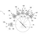
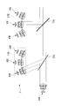
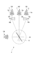
- the illumination device 1 is, as shown in FIG. 1, one of six light sources 10A, 10B, 10C, 10D, 10E, 10F, and these light sources 10A, 10B, 10C, 10D, 10E, 10F.
- Light from the other light source and a dichroic mirror (optical element) 13 for reflecting light from other light sources, and a rotation mechanism (optical element rotation means for rotating the dichroic mirror 13 about the rotation axis of the dichroic mirror 13
- a control unit (not shown) for controlling the rotation angle of the dichroic mirror by the rotation mechanism.
- Each of the light sources 10A, 10B, 10C, 10D, 10E, and 10F includes a light emitting element 11 such as an LED and collimating lenses 12a and 12b for collimating light emitted from the light emitting element 11, respectively.
- the light sources 10B, 10C, 10D, 10E, and 10F are arrayed such that the optical axes cross at one point on the dichroic mirror 13, and are annularly arranged at equal intervals from the left side in FIG.
- the arrangement intervals of the light sources 10A, 10B, 10C, 10D, 10E and 10F do not necessarily have to be equal intervals, and the optical axis of the light emitted from each of the light sources 10A, 10B, 10C, 10D, 10E and 10F is one point It should just be arrange
- the light source includes the light emitting element 11 and the collimating lenses 12a and 12b.
- the present invention is not limited to such a configuration.
- the collimating lenses 12a and 12b are not provided. It can also be done.
- the light source 10A is disposed at the left end, and the light source 10D is disposed at a position forming an angle of 90 ° with the direction of the light path of the light source 10A.
- the light source 10B is disposed between the light source 10A and the light source 10D at a position inclined 45 ° from the light source 10A and the light source 10D around the rotation axis of the dichroic mirror 13.
- the light source 10C is disposed between the light source 10B and the light source 10D, at a position inclined by 22.5 ° from the light source 10B and the light source 10D, respectively, around the rotation axis of the dichroic mirror 13.
- the light source 10F is disposed at a position inclined 45 ° in a direction away from the light source 10A with reference to the light source 10D with the rotation axis of the dichroic mirror 13 as a center.
- the light source 10E is disposed between the light source 10D and the light source 10F, at a position tilted by 22.5 ° from the light source 10D and the light source 10F, respectively, around the rotation axis of the dichroic mirror 13.
- the light sources 10A, 10B, 10C, 10D, 10E, and 10F are arranged in an annular shape located on the same circumference, and arranged so that the optical paths of the light from the respective light sources intersect at the center of the annular ring. It is done.
- the light sources 10A, 10B, 10C, 10D, 10E and 10F emit light in different wavelength regions. Specifically, the light source 10A has a wavelength of 400 nm, the light source 10B has a wavelength of 550 nm, the light source 10C has a wavelength of 600 nm, 10D emits light of 650 nm, the light source 10E of 700 nm, and the light source 10F of 750 nm.
- the light sources 10B, 10C, 10D, 10E and 10F are annular and equally spaced in order of shorter wavelength range from the left side in FIG. Is located in
- the dichroic mirror 13 has so-called short path characteristics and is disposed at the centers of the light sources 10A, 10B, 10C, 10D, 10E and 10F arranged in an annular shape, that is, the respective light sources 10A, 10B, 10C, 10D, 10E and 10F. At a position where the optical paths intersect, the dichroic mirror 13 is disposed so as to rotate about its center.
- the dichroic mirror 13 transmits the light from the light source 10A, reflects the light from the light sources 10B, 10C, 10D, 10E and 10F, and causes the reflected light to enter the optical path of the light from the light source 10A.
- the dichroic mirror is disposed at 45 ° with respect to the optical axis, and emits combined light by emitting the incident light and the reflected light in the same direction.
- the light from the light source 10A is incident with the dichroic mirror 13 inclined at 45 ° to the light path of the light source 10A, and is 45 ° from the normal to the dichroic mirror 13.
- the dichroic mirror 13 has a short path characteristic, the light incident from the light source 10A must have a shorter wavelength than the light reflected by the dichroic mirror 13. In the case of a dichroic mirror having long pass characteristics, the opposite is true.
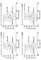
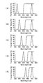
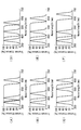
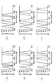
- FIG. 2 shows the optical characteristics of the dichroic mirror.
- the dichroic mirror shifts to the longer wavelength side as compared with the optical characteristics, that is, the reflectance characteristics and the transmittance characteristics at 45 °.
- the incident angle is deeper than 45 °, it shifts to the short wavelength side.
- the sum of the reflectance and transmittance of the dichroic mirror is about 100% except for the Fresnel loss in the dichroic mirror. That is, the sum of the reflectance in FIG. 2A and the transmittance in FIG. 2B is always about 100% at any wavelength.
- the dichroic mirror 13 has a short path characteristic, and the light source 10A is light passing through the dichroic mirror. Therefore, when the dichroic mirror is rotated clockwise about its rotation axis, the incident angle becomes shallow. Therefore, the transmission characteristics shift to the long wavelength side. Further, in the light sources 10B, 10C, 10D, 10E, and 10F arranged in an annular shape, the reflection characteristic is also shifted to the long wavelength side according to the rotation angle of the dichroic mirror 13. Therefore, if the wavelength of light reflected by the dichroic mirror 13 is lengthened as the clockwise rotation angle of the dichroic mirror 13 increases, efficient illumination can be performed without being affected by the oblique incident characteristics of the dichroic mirror. become. From such a reason, in the present embodiment, the light sources 10B, 10C, 10D, 10E, and 10F are arranged in an annular shape at equal intervals in the order of shorter wavelength regions from the left side in FIG.
- the rotation mechanism 14 rotates the dichroic mirror 13 by a predetermined rotation angle in the arrangement direction of the light sources 10A, 10B, 10C, 10D, 10E and 10F based on a control signal from the control unit described later, and tilts the dichroic mirror 13 Adjust.
- the rotation mechanism 14 can be configured, for example, using a motor or the like.
- the control unit adjusts the rotation angle of the dichroic mirror 13 so that the light from the light source 10B, 10C, 10D, 10E, and 10F enters the light path of the light from the light source 10A at the desired incident angle with respect to the rotation mechanism 14 Control signal is generated and output to the rotation mechanism 14. Thereby, the dichroic mirror 13 is controlled by the rotation mechanism 14 to a desired rotation angle. Further, the control unit controls lighting or extinguishing of the light sources 10A, 10B, 10C, 10D, 10E, and 10F.
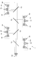
- FIG. , FIG. 4 and FIG. 5 a case where the light from the light source 10A and the light from the light sources 10B, 10C, 10D, 10E, and 10F are selected to generate and emit combined light is shown in FIG. , FIG. 4 and FIG. 5 will be described.
- FIG. 3A shows an example in the case of generating combined light of the light from the light source 10A and the light from the light source 10B.
- the dichroic mirror 13 is rotated by 22.5 ° counterclockwise around the rotation axis of the dichroic mirror 13 from the state of 45 ° inclining with respect to the direction of the light path of the light source 10A.
- the optical characteristics of the dichroic mirror 13 at this time are as shown in FIG. 4 (A) and FIG. 5 (A). Accordingly, the light from the light source 10A is transmitted through the dichroic mirror 13, and the light from the light source 10B is reflected by the dichroic mirror 13 to generate combined light.
- the combined light of the light from the light source 10A and the light from the light source 10F is generated.
- the dichroic mirror 13 is rotated 22.50 ° clockwise from the 45 ° inclined state.
- the optical characteristics of the dichroic mirror 13 are as shown in FIG. 4 (E) and FIG. 5 (E). Accordingly, the light source 10A transmits the dichroic mirror 13, and the light source 10F reflects the dichroic mirror 13 to generate combined light.
- the light from the light source 10A passes through the transmitted light path that passes straight through the dichroic mirror 13 while adjusting the rotation angle of the dichroic mirror 13 by the rotation mechanism 14 by the operation of the control unit
- the light from any of the other light sources 10B, 10C, 10D, 10E and 10F is reflected by the dichroic mirror 13 and enters the transmission light path of the light from the light source 10A.
- the rotation angle of the dichroic mirror 13 is switched by the rotation mechanism 14, it is possible to switch the light source for emitting the light to be incident on the transmission light path.
- light from three or more light sources 10A, 10B, 10C, 10D, 10E, and 10F can be made incident on one optical path by one dichroic mirror 13, and light loss during transmission or reflection of light can be reduced. It can be suppressed. Therefore, light of a plurality of different wavelengths can be appropriately selected, and the light guiding efficiency can be improved to emit light of higher luminance.
- This modification differs only in the characteristics of the illumination device and the dichroic mirror in the first embodiment described above. Therefore, the arrangement position and the like of the light source are the same as those of the above-described first embodiment, and therefore, will be described below with reference to FIG. That is, although what has a short pass characteristic was applied to dichroic mirror 13 in a 1st embodiment, a dichroic mirror having a long pass characteristic is applied in this modification. Therefore, as the light source 10A, the longest wavelength region among six light sources is applied.
- 750 nm, 400 nm, 450 nm, 500 nm, 550 nm, and 600 nm are applied to the light sources 10A, 10B, 10C, 10D, 10E, and 10F, respectively.
- FIG. 10 a case where light from the light source 10A and light from the light sources 10B, 10C, 10D, 10E, and 10F are selected to generate and emit combined light is shown in FIG. It demonstrates with reference to FIG.6 and FIG.7.
- FIG. 3A shows an example in the case of generating combined light of the light from the light source 10A and the light from the light source 10B.
- the dichroic mirror 13 is rotated by 22.5 degrees counterclockwise from the 45 ° inclined state.
- the optical characteristics of the dichroic mirror at this time are as shown in FIG. 6 (A) and FIG. 7 (A). Accordingly, the light from the light source 10A is transmitted through the dichroic mirror 13, and the light from the light source 10B is reflected by the dichroic mirror 13 to generate combined light.
- the dichroic mirror 13 is inclined at 45 °.
- the optical characteristics of the dichroic mirror 13 are as shown in FIG. 6 (C) and FIG. 7 (C). Accordingly, the light from the light source 10A is transmitted through the dichroic mirror, and the light from the light source 10D is reflected by the dichroic mirror to be color synthesized and illuminated.
- the combined light of the light from the light source 10A and the light from the light source 10F is generated.
- the dichroic mirror 13 is rotated 22.50 ° clockwise from the 45 ° inclined state.
- the optical characteristics of the dichroic mirror 13 are as shown in FIG. 6 (E) and FIG. 7 (E). Accordingly, the light source 10A transmits the dichroic mirror 13, and the light source 10F reflects the dichroic mirror 13 to generate combined light.
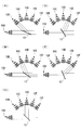
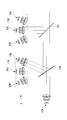
- the illumination device 2 which concerns on 2nd Embodiment is demonstrated with reference to drawings.
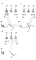
- the illumination device 2 according to the present embodiment includes a light source unit 17 having seven light sources, two dichroic mirrors 13a and 13b, and rotation mechanisms 14a and 14b for rotating the dichroic mirrors 13a and 13b. Have.
- the dichroic mirrors 13a and 13b are described as having short path characteristics.
- the light source unit 17 includes a light source 10A that emits light transmitted through the dichroic mirrors 13a and 13b, a light source group 17A (light sources 10B, 10C, and 10D) that emits light reflected by the dichroic mirrors 13a and 13b, and a light source group 17B (light sources 10E, 10F, 10G).
- the light sources 10B, 10C, and 10D constituting the light source group 17A are arranged in the same annular shape in the same circle, and are arranged such that the optical paths of the light from the respective light sources intersect at the center of this ring. ing.
- the light sources 10E, 10F, and 10G constituting the light source group 17B are also arranged in an annular shape located on the same circumference, so that the optical paths of light from the respective light sources intersect at the center of this annular ring. It is arranged.
- the light source 10A, the light source group 17A and the light source group 17B are arranged such that the intersection position of each light path of the light source group 17A and the intersection position of each light path of the light source group 17B are located on the optical path of light from the light source 10A. ing.
- the light source 10B emits light with a wavelength of 450 nm, and is disposed at an inclination of 67.5 ° in the optical path direction of the light source 10A with reference to the light source 10A.
- the light source 10C emits light of 500 nm and is disposed at an inclination of 90 ° in the optical path direction from the light source 10A.
- the light source 10D emits light having a wavelength of 550 nm, and is disposed so as to be inclined at 22.5 ° in the optical path direction of the light source 10A from the light source 10C.
- the light source 10E emits light with a wavelength of 600 nm, and is disposed at an inclination of 67.5 ° in the optical path direction of the light source 10A with reference to the light source 10A.
- the light source 10F emits light having a wavelength of 650 nm, and is arranged to be inclined by 90 ° in the optical path direction from the light source 10A.
- the light source 10G emits light having a wavelength of 700 nm, and is disposed so as to be inclined at 22.5 ° in the optical path direction of the light source 10A from the light source 10C.
- the dichroic mirror 13a is disposed at the intersection position of each light path of the light source group 17A, and the dichroic mirror 13b is disposed at the intersection position of each light path of the light source group 17B.
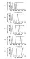
- FIG. 9 shows an example in the case of generating combined light of the light from the light source 10A and the light from the light source 10B and the light source 10F.
- the dichroic mirror 13a is rotated 11.25 ° counterclockwise from the 45 ° inclined state.
- the dichroic mirror 13 b is in a state of 45 ° inclination.
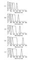
- the optical characteristics of the dichroic mirrors 13a and 13b are as shown in FIGS. 15 (A) and 16 (A). Accordingly, the light source 10A transmits the dichroic mirror 13a and then transmits the dichroic mirror 13b, and the light source 10B reflects the dichroic mirror 13a and then transmits the dichroic mirror 13b. Then, the light source 10F reflects the dichroic mirror 13b to generate combined light.
- FIG. 10 shows an example of generating combined light of the light from the light source 10A and the light from the light source 10C and the light source 10F.
- the dichroic mirrors 13a and 13b are both inclined at 45 °.
- the optical characteristics of the dichroic mirrors 13a and 13b are as shown in FIG. 15 (B) and FIG. 16 (B). Therefore, the light source 10A transmits the dichroic mirror 13a and then transmits the dichroic mirror 13b, and the light source 10C reflects the dichroic mirror 13a and then transmits the dichroic mirror 13b. Then, the light source 10F reflects the dichroic mirror 13b to generate combined light.
- FIG. 11 shows an example in the case of generating combined light of the light from the light source 10A and the light from the light source 10D and the light source 10F.
- the dichroic mirror 13a is rotated 11.25 ° clockwise from the 45 ° inclined state.
- the dichroic mirror 13 b is in a state of 45 ° inclination.
- the optical characteristics of the dichroic mirrors 13a and 13b are as shown in FIG. 15 (C) and FIG. 16 (C). Therefore, the light source 10A transmits the dichroic mirror 13a and then the dichroic mirror 13b, and the light source 10D reflects the dichroic mirror 13a and then transmits the dichroic mirror 13b. Then, the light source 10F reflects the dichroic mirror 13b to generate combined light.
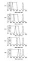
- FIG. 12 shows an example of generating combined light of the light from the light source 10A and the light from the light source 10C and the light source 10E.
- the dichroic mirror 13a is in a 45 ° inclined state.
- the dichroic mirror 13 b is rotated 11.25 ° clockwise from the 45 ° inclined state.
- the optical characteristics of the dichroic mirrors 13a and 13b are as shown in FIG. 15 (D) and FIG. 16 (D). Therefore, the light source 10A transmits the dichroic mirror 13a and then the dichroic mirror 13b, and the light source 10D reflects the dichroic mirror 13a and then transmits the dichroic mirror 13b. Then, the light source 10E reflects the dichroic mirror 13b to generate combined light.
- FIG. 13 shows an example in the case of generating combined light of the light from the light source 10A and the light from the light source 10C and the light from the light source 10F.
- Both of the dichroic mirrors 13a and 13b are inclined 45 °.
- the optical characteristics of the dichroic mirrors 13a and 13b are as shown in FIG. 15 (E) and FIG. 16 (E). Accordingly, the light source 10A transmits the dichroic mirror 13a and then transmits the dichroic mirror 13b, and the light source 10F reflects the dichroic mirror 13a and then transmits the dichroic mirror 13b. Then, the light source 10E reflects the dichroic mirror 13b to generate combined light.
- FIG. 14 shows an example of generating combined light of the light from the light source 10A and the light from the light source 10C and the light from the light source 10G.
- the dichroic mirror 13a is in a 45 ° inclined state.
- the dichroic mirror 13 b is rotated 11.25 ° clockwise from the 45 ° inclined state.
- the optical characteristics of the dichroic mirrors 13a and 13b are as shown in FIG. 15 (F) and FIG. 16 (F). Therefore, the light source 10A transmits the dichroic mirror 13a and then transmits the dichroic mirror 13b, and the light source 10C reflects the dichroic mirror 13a and then transmits the dichroic mirror 13b. Then, the light source 10G reflects the dichroic mirror 13b to generate combined light.
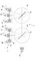
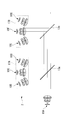
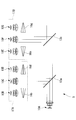
- the illumination device 3 according to the present modification includes a light source unit including four light source groups, four dichroic mirrors 13a, 13b, 13c, 13d, and these dichroic mirrors 13a, 13b, 13c, It has rotation mechanisms 14a and 14b for rotating 13d.
- the dichroic mirrors 13a, 13b, 13c, and 13d are described as having short path characteristics.
- the light source unit of the illumination device 3 includes the light source 10A and the light source groups 17A, 17B, 17C, and 17D, and the light sources constituting the light source groups 17A, 17B, 17C, and 17D are respectively disposed in an annular shape.
- the center of the light source group 17A, 17B, 17C, 17D is the cross point of the light from each light source.
- the light source 10A and the light source groups 17A, 17B, 17C, 17D are positioned such that the intersection position of each light path from the light sources constituting the light source groups 17A, 17B, 17C, 17D is located on the light path of light from the light source 10A. Is arranged.
- the dichroic mirrors 13a, 13b, 13c and 13d are positioned at the respective intersection positions.
- the light source 10A that emits light with a wavelength of 400 nm is disposed at the left end.
- the light source group 17A has the light sources 10B, 10C, and 10D disposed in an annular shape centered on the position of the dichroic mirror 13a, and the light source 10B is in the light path direction of the light source 10A with reference to the light source 10A in FIG. It is placed at an inclination of 67.5 ° clockwise.
- the light source 10C is inclined by 22.5 ° clockwise in the light path direction of the light source 10A from the light source 10B, and the light source 10D is arranged by 22.5 ° clockwise in the light path direction of the light source 10A from the light source 10C.
- the light source 10B emits light with a wavelength of 430 nm
- the light source 10C emits light with a wavelength of 460 nm
- the light source 10D emits light with a wavelength of 490 nm.
- the light source group 17B has the light sources 10E, 10F, and 10G disposed in an annular shape centered on the position of the dichroic mirror 13b, and the light source 10E is the light source 10A of FIG. It is disposed at an inclination of 67.5 ° counterclockwise in the light path direction.
- the light source 10F is inclined 22.5 ° counterclockwise from the light source 10E toward the light path of the light source 10A
- the light source 10G is inclined 22.5 ° counterclockwise from the light source 10F toward the light path from the light source 10A. It is arranged.
- the light source 10E emits light of wavelength 520 nm
- the light source 10F emits light of wavelength 550 nm
- the light source 10G emits light of wavelength 580 nm.
- the light source group 17C has the light sources 10H, 10I and 10J arranged in a ring shape centering on the position of the dichroic mirror 13c, and the light source 10H is in the light path direction of the light source 10A with reference to the light source 10A in FIG. It is placed at an inclination of 67.5 ° clockwise.
- the light source 10I is inclined by 22.5 ° clockwise in the light path direction of the light source 10A from the light source 10H
- the light source 10J is disposed by 22.5 ° clockwise in the light path direction of the light source 10A from the light source 10H. ing.
- the light source 10H emits light having a wavelength of 610 nm
- the light source 10I emits light having a wavelength of 640 nm
- the light source 10J emits light having a wavelength of 670 nm.
- the light source group 17D has the light sources 10K, 10L and 10M arranged in an annular shape centering on the position of the dichroic mirror 13d, and the light source 10K is in the light path direction of the light source 10A with reference to the light source 10A in FIG. It is placed counterclockwise at 67.5 °.
- the light source 10L is inclined 22.5 ° counterclockwise from the light source 10K toward the light path of the light source 10A
- the light source 10M is inclined 22.5 ° counterclockwise from the light source 10L toward the light path from the light source 10L. It is arranged.
- the light source 10K emits light having a wavelength of 700 nm
- the light source 10L emits light having a wavelength of 730 nm
- the light source 10M emits light having a wavelength of 760 nm.
- the illumination device 4 according to the third embodiment will be described below with reference to the drawings.
- the light sources are not arranged in an annular shape as in the above-described embodiments, and the light sources 10B, 10C, and 10D are linearly arranged.
- the light source 10A emitting the light of 400 nm transmitting the dichroic mirror 13 having short path characteristics is disposed at the left end, and the light sources 10B, 10C, and 10D are disposed at positions orthogonal to the light path of the light source 10A. It is arranged at equal intervals.
- the light source 10B and the light source 10D have the prisms 16b and 16d as optical path changing members, the light from the light source 10B is the same as the light path of the light from the light source 10C by the prism 16b and the light from the light source 10D by the prism 16d. It is supposed to cross at the position. Then, the intersection position is on the light path of the light from the light source 10A.
- the light source 10B emits light with a wavelength of 450 nm
- the light source 10C emits light with a wavelength of 500 nm
- the light source 10D emits light with a wavelength of 550 nm.
- the illumination device 4 configured as described above, for example, a case where the light from the light source 10A and the light from the light sources 10B, 10C, and 10D are selected to generate and emit combined light will be described with reference to FIG. explain.
- the light from the light source 10B and the light source 10D is inclined by 22.5 ° with respect to the light from the light source 10C and enters the dichroic mirror 13 by the prisms 16b and 16d.
- FIG. 19A shows an example of generating combined light of the light from the light source 10A and the light from the light source 10B.
- the dichroic mirror 13 is rotated by 22.5 degrees counterclockwise from the 45 ° inclined state.
- the optical characteristics of the dichroic mirror at this time are as shown in FIG. 15 (A) and FIG. 16 (A). Accordingly, the light from the light source 10A is transmitted through the dichroic mirror 13, and the light from the light source 10B is reflected by the dichroic mirror 13 to generate combined light.
- the dichroic mirror 13 is inclined at 45 °.
- the optical characteristics of the dichroic mirror 13 are as shown in FIG. 15 (C) and FIG. 16 (C). Accordingly, the light from the light source 10A is transmitted through the dichroic mirror, and the light from the light source 10D is reflected by the dichroic mirror to be color synthesized and illuminated.
- each light source is disposed on a straight line, and two light source groups each including three light sources disposed on the straight line are provided.
- the light source 10A for emitting light of 400 nm that transmits the dichroic mirrors 13a and 13b having short path characteristics is disposed at the left end, and is orthogonal to the light path of the light source 10A.
- a light source group 17A consisting of 10D and a light source group 17B consisting of light sources 10E, 10F, 10G are arranged at equal intervals.
- the light source 10B and the light sources 10D, 10E and 10G have prisms 16b, 16d, 16e and 16f as light path changing members, the light from the light source 10B is by the prism 16b and the light from the light source 10D is by the prism 16d It intersects at the same position as the optical path of light from 10C. Similarly, the light from the light source 10E is crossed by the prism 16e, and the light from the light source 10G is crossed by the prism 16g at the same position as the light path of the light from the light source 10C. And each intersection position becomes an optical path of the light from light source 10A.
- LED was applied as a light emitting element, it is not restricted to this, for example, LD, a lamp, etc. are applicable.
- dichroic mirror was applied as an optical element, it is not restricted to this, For example, a dichroic prism etc. can also be applied.
- various arrangements of light sources can be made by rotatably providing the dichroic mirror.
- the light from the light source 10A passes through the transmitted light path that passes straight through the dichroic mirror 13, while adjusting the rotation angle of the dichroic mirror 13 by the rotation mechanism, any of the other light sources 10B, 10C, 10D, etc.
- the light from the light source 10 is reflected by the dichroic mirror 13 and enters the transmission light path of the light from the light source 10A.
- the rotation angle of the dichroic mirror 13 is switched by the rotation mechanism 14, it is possible to switch the light source for emitting the light to be incident on the transmission light path. That is, light from three or more light sources 10A, 10B, 10C, 10D, etc.
Landscapes
- Physics & Mathematics (AREA)
- General Physics & Mathematics (AREA)
- Optics & Photonics (AREA)
- Astronomy & Astrophysics (AREA)
- Spectroscopy & Molecular Physics (AREA)
- Engineering & Computer Science (AREA)
- General Engineering & Computer Science (AREA)
- Projection Apparatus (AREA)
- Non-Portable Lighting Devices Or Systems Thereof (AREA)
Abstract
La présente invention permet d'émettre de la lumière ayant une luminance plus élevée en sélectionnant de la lumière ayant une pluralité de longueurs d'onde différentes selon les besoins, et en améliorant l'efficacité du guidage de la lumière. L'invention concerne un appareil d'éclairage (1), qui comprend les éléments suivants : trois ou plusieurs sources de lumière (10A, 10B, 10C, 10D, 10E, 10F), qui sont disposées de telle sorte que leurs axes optiques se croisent au niveau d'un point, et qui délivrent en sortie la lumière dans différentes zones de longueur d'onde ; un élément optique (13), qui passe à travers la lumière émise à partir d'une source de lumière parmi les sources de lumière, réfléchit la lumière émise par d'autres sources de lumière et amène la lumière à entrer dans un trajet optique de la lumière émise à partir d'une source de lumière ; et un moyen de rotation de l'élément optique (14), qui fait tourner l'élément optique dans la direction dans laquelle sont disposées les sources de lumière.
Priority Applications (3)
| Application Number | Priority Date | Filing Date | Title |
|---|---|---|---|
| EP12865111.4A EP2803899A4 (fr) | 2012-01-12 | 2012-12-25 | Appareil d'éclairage |
| CN201280066532.4A CN104040243A (zh) | 2012-01-12 | 2012-12-25 | 照明装置 |
| US14/323,801 US9915413B2 (en) | 2012-01-12 | 2014-07-03 | Illumination apparatus |
Applications Claiming Priority (2)
| Application Number | Priority Date | Filing Date | Title |
|---|---|---|---|
| JP2012004115A JP2013143329A (ja) | 2012-01-12 | 2012-01-12 | 照明装置 |
| JP2012-004115 | 2012-01-12 |
Related Child Applications (1)
| Application Number | Title | Priority Date | Filing Date |
|---|---|---|---|
| US14/323,801 Continuation US9915413B2 (en) | 2012-01-12 | 2014-07-03 | Illumination apparatus |
Publications (1)
| Publication Number | Publication Date |
|---|---|
| WO2013105432A1 true WO2013105432A1 (fr) | 2013-07-18 |
Family
ID=48781390
Family Applications (1)
| Application Number | Title | Priority Date | Filing Date |
|---|---|---|---|
| PCT/JP2012/083518 WO2013105432A1 (fr) | 2012-01-12 | 2012-12-25 | Appareil d'éclairage |
Country Status (5)
| Country | Link |
|---|---|
| US (1) | US9915413B2 (fr) |
| EP (1) | EP2803899A4 (fr) |
| JP (1) | JP2013143329A (fr) |
| CN (1) | CN104040243A (fr) |
| WO (1) | WO2013105432A1 (fr) |
Cited By (1)
| Publication number | Priority date | Publication date | Assignee | Title |
|---|---|---|---|---|
| CN106574755A (zh) * | 2014-08-22 | 2017-04-19 | 奥林巴斯株式会社 | 光源装置 |
Families Citing this family (4)
| Publication number | Priority date | Publication date | Assignee | Title |
|---|---|---|---|---|
| CN106950687B (zh) * | 2016-01-06 | 2021-01-01 | 松下知识产权经营株式会社 | 图像生成系统以及图像生成方法 |
| CN116774453A (zh) | 2018-06-22 | 2023-09-19 | 奇跃公司 | 用于rgb照明器的方法和系统 |
| JP2022057427A (ja) * | 2020-09-30 | 2022-04-11 | レボックス株式会社 | 光源装置 |
| DE102021100572A1 (de) | 2021-01-13 | 2022-07-14 | Happersberger Otopront Gmbh | Beleuchtungsvorrichtung für ein Endoskopiesystem und Endoskopiesystem mit einer Beleuchtungsvorrichtung |
Citations (3)
| Publication number | Priority date | Publication date | Assignee | Title |
|---|---|---|---|---|
| JPH0566366A (ja) * | 1991-09-10 | 1993-03-19 | Hitachi Ltd | 液晶プロジエクシヨン装置 |
| JP2001042431A (ja) | 1999-07-30 | 2001-02-16 | Nitto Kogaku Kk | 光源装置およびプロジェクタ装置 |
| JP2004138866A (ja) * | 2002-10-18 | 2004-05-13 | Sony Corp | 光学装置 |
Family Cites Families (12)
| Publication number | Priority date | Publication date | Assignee | Title |
|---|---|---|---|---|
| JP3914819B2 (ja) * | 2002-05-24 | 2007-05-16 | オリンパス株式会社 | 照明装置及び画像投影装置 |
| JP2004335992A (ja) * | 2003-04-18 | 2004-11-25 | Victor Co Of Japan Ltd | 光源装置及びこの光源装置を適用した投射型表示装置 |
| US7101050B2 (en) * | 2004-05-14 | 2006-09-05 | 3M Innovative Properties Company | Illumination system with non-radially symmetrical aperture |
| JP2006023436A (ja) * | 2004-07-07 | 2006-01-26 | Olympus Corp | 照明装置及びプロジェクタ |
| DE102005027312A1 (de) * | 2005-06-13 | 2006-12-14 | Sensovation Ag | Mikroskop |
| JP2007157548A (ja) * | 2005-12-06 | 2007-06-21 | Fujinon Corp | 光源装置及びプロジェクタ |
| EP1918757A1 (fr) * | 2006-11-02 | 2008-05-07 | Olympus Corporation | Appareil d'éclairage de microscope |
| EP2283391B1 (fr) * | 2008-05-15 | 2014-07-23 | 3M Innovative Properties Company | Élément optique et combineur de couleurs |
| US8746891B2 (en) * | 2009-07-13 | 2014-06-10 | Martin Professional A/S | Color-combining illumination device |
| JP2011243440A (ja) * | 2010-05-19 | 2011-12-01 | Olympus Corp | 照明装置 |
| CN201706387U (zh) * | 2010-06-19 | 2011-01-12 | 麦克奥迪实业集团有限公司 | 可快速切换不同波长的照明装置 |
| JP5966363B2 (ja) * | 2011-06-20 | 2016-08-10 | 株式会社リコー | 光源装置及び画像投射装置 |
-
2012
- 2012-01-12 JP JP2012004115A patent/JP2013143329A/ja active Pending
- 2012-12-25 WO PCT/JP2012/083518 patent/WO2013105432A1/fr active Application Filing
- 2012-12-25 CN CN201280066532.4A patent/CN104040243A/zh active Pending
- 2012-12-25 EP EP12865111.4A patent/EP2803899A4/fr not_active Withdrawn
-
2014
- 2014-07-03 US US14/323,801 patent/US9915413B2/en active Active
Patent Citations (3)
| Publication number | Priority date | Publication date | Assignee | Title |
|---|---|---|---|---|
| JPH0566366A (ja) * | 1991-09-10 | 1993-03-19 | Hitachi Ltd | 液晶プロジエクシヨン装置 |
| JP2001042431A (ja) | 1999-07-30 | 2001-02-16 | Nitto Kogaku Kk | 光源装置およびプロジェクタ装置 |
| JP2004138866A (ja) * | 2002-10-18 | 2004-05-13 | Sony Corp | 光学装置 |
Non-Patent Citations (1)
| Title |
|---|
| See also references of EP2803899A4 |
Cited By (1)
| Publication number | Priority date | Publication date | Assignee | Title |
|---|---|---|---|---|
| CN106574755A (zh) * | 2014-08-22 | 2017-04-19 | 奥林巴斯株式会社 | 光源装置 |
Also Published As
| Publication number | Publication date |
|---|---|
| EP2803899A1 (fr) | 2014-11-19 |
| US9915413B2 (en) | 2018-03-13 |
| US20140321114A1 (en) | 2014-10-30 |
| CN104040243A (zh) | 2014-09-10 |
| EP2803899A4 (fr) | 2015-07-08 |
| JP2013143329A (ja) | 2013-07-22 |
Similar Documents
| Publication | Publication Date | Title |
|---|---|---|
| JP6171345B2 (ja) | 照明光源装置及びこの照明光源装置を備えた投射装置及び投射装置の制御方法 | |
| WO2013105432A1 (fr) | Appareil d'éclairage | |
| JP6056293B2 (ja) | 照明光源装置及びこの照明光源装置を備えた投射装置及び投射装置の制御方法 | |
| JP2020202182A (ja) | 照明装置および投影装置 | |
| JP6102132B2 (ja) | 照明光源装置及びこの照明光源装置を備えた投射装置及び投射装置の制御方法 | |
| WO2011092841A1 (fr) | Système optique d'éclairage et projecteur utilisant celui-ci | |
| JP6164674B2 (ja) | ランプ、及びこのようなランプを用いるための方法 | |
| JP2013076968A (ja) | 照明装置、ならびに、投射装置および投射装置の制御方法 | |
| JP2011243440A (ja) | 照明装置 | |
| TW201235620A (en) | Colour-tunable light source unit with phosphor element | |
| JP2014199412A (ja) | 照明光源装置、およびそれを備える投射装置 | |
| JP6255680B2 (ja) | 照明光源装置とこれを用いた投射装置 | |
| JP5598968B2 (ja) | 医用光学観察装置の照明デバイス用の光源構成 | |
| WO2017051868A1 (fr) | Dispositif d'éclairage | |
| JP5394805B2 (ja) | リング照明装置 | |
| US9737204B2 (en) | Retinal imaging apparatus and method | |
| US9903543B2 (en) | Lighting device providing light mixed from several light sources | |
| RU2010154659A (ru) | Светоизлучающее устройство и способ излучения света | |
| JP4579554B2 (ja) | 顕微鏡用照明装置 | |
| US11835202B2 (en) | Illumination device | |
| JP2017117725A (ja) | 車両用前照灯装置 | |
| JP6979168B2 (ja) | 照明装置 | |
| WO2023042274A1 (fr) | Dispositif de source de lumière et système d'endoscope équipé de celui-ci | |
| WO2012111435A1 (fr) | Dispositif d'éclairage | |
| JP6048051B2 (ja) | 照明装置、顕微鏡システム、顕微鏡、制御方法 |
Legal Events
| Date | Code | Title | Description |
|---|---|---|---|
| 121 | Ep: the epo has been informed by wipo that ep was designated in this application |
Ref document number: 12865111 Country of ref document: EP Kind code of ref document: A1 |
|
| WWE | Wipo information: entry into national phase |
Ref document number: 2012865111 Country of ref document: EP |
|
| NENP | Non-entry into the national phase |
Ref country code: DE |