WO2013105432A1 - Illuminating apparatus - Google Patents
Illuminating apparatus Download PDFInfo
- Publication number
- WO2013105432A1 WO2013105432A1 PCT/JP2012/083518 JP2012083518W WO2013105432A1 WO 2013105432 A1 WO2013105432 A1 WO 2013105432A1 JP 2012083518 W JP2012083518 W JP 2012083518W WO 2013105432 A1 WO2013105432 A1 WO 2013105432A1
- Authority
- WO
- WIPO (PCT)
- Prior art keywords
- light
- light source
- dichroic mirror
- sources
- source
- Prior art date
Links
Images


Classifications
-
- F—MECHANICAL ENGINEERING; LIGHTING; HEATING; WEAPONS; BLASTING
- F21—LIGHTING
- F21V—FUNCTIONAL FEATURES OR DETAILS OF LIGHTING DEVICES OR SYSTEMS THEREOF; STRUCTURAL COMBINATIONS OF LIGHTING DEVICES WITH OTHER ARTICLES, NOT OTHERWISE PROVIDED FOR
- F21V14/00—Controlling the distribution of the light emitted by adjustment of elements
-
- G—PHYSICS
- G02—OPTICS
- G02B—OPTICAL ELEMENTS, SYSTEMS OR APPARATUS
- G02B27/00—Optical systems or apparatus not provided for by any of the groups G02B1/00 - G02B26/00, G02B30/00
- G02B27/10—Beam splitting or combining systems
- G02B27/14—Beam splitting or combining systems operating by reflection only
- G02B27/141—Beam splitting or combining systems operating by reflection only using dichroic mirrors
-
- G—PHYSICS
- G02—OPTICS
- G02B—OPTICAL ELEMENTS, SYSTEMS OR APPARATUS
- G02B26/00—Optical devices or arrangements for the control of light using movable or deformable optical elements
- G02B26/007—Optical devices or arrangements for the control of light using movable or deformable optical elements the movable or deformable optical element controlling the colour, i.e. a spectral characteristic, of the light
-
- G—PHYSICS
- G02—OPTICS
- G02B—OPTICAL ELEMENTS, SYSTEMS OR APPARATUS
- G02B27/00—Optical systems or apparatus not provided for by any of the groups G02B1/00 - G02B26/00, G02B30/00
- G02B27/10—Beam splitting or combining systems
- G02B27/1006—Beam splitting or combining systems for splitting or combining different wavelengths
-
- G—PHYSICS
- G02—OPTICS
- G02B—OPTICAL ELEMENTS, SYSTEMS OR APPARATUS
- G02B21/00—Microscopes
- G02B21/06—Means for illuminating specimens
-
- G—PHYSICS
- G02—OPTICS
- G02B—OPTICAL ELEMENTS, SYSTEMS OR APPARATUS
- G02B23/00—Telescopes, e.g. binoculars; Periscopes; Instruments for viewing the inside of hollow bodies; Viewfinders; Optical aiming or sighting devices
- G02B23/24—Instruments or systems for viewing the inside of hollow bodies, e.g. fibrescopes
- G02B23/2407—Optical details
- G02B23/2453—Optical details of the proximal end
Definitions
- the present invention relates to a lighting device.
- fluorescence observation in which fluorescence emitted from a living body is detected and observed by irradiating a subject with light of a specific wavelength is widely performed.
- fluorescence observation in order to detect fluorescence from an observation object efficiently, it is necessary to irradiate light of a wavelength according to the excitation light characteristic of a fluorescence reagent or a living body.
- Patent Document 1 includes three light sources (LEDs) and two dichroic mirrors, appropriately switching each light source, and color combining light of a plurality of wavelengths with the dichroic mirrors. What can select and output the wavelength of the light irradiated to observation object is described.
- a plurality of dichroic mirrors are used to color combine light of a plurality of wavelengths. More specifically, the number of dichroic mirrors which is smaller by one than the number of light sources is disposed. For this reason, the light emitted from at least one light source has to transmit the number of dichroic mirrors which is one less than the number of light sources. Therefore, the light emitted from the light source loses light quantity every time it passes through the dichroic mirror, so the light guiding efficiency is low, and a sufficient light quantity can not be obtained in the observation object.
- This invention is made in view of such a situation, Comprising:
- the light of a several different wavelength is selected suitably, And a light-guide efficiency can be improved and the illuminating device which can irradiate the light of higher brightness. Intended to provide.
- the present invention adopts the following means.
- three or more light sources arranged such that optical axes are crossed at one point and which emit light of different wavelength regions, light from one of the light sources is transmitted, and
- An illumination device comprising: an optical element that reflects light from a light source and enters an optical path of light from the one light source; and an optical element rotation unit that rotates the optical element in the arrangement direction of the light source.
- the light from the one light source passes through the transmitted light path that passes straight through the optical element.
- the rotation angle of the optical element by the optical element rotation means is adjusted by the operation of the control means, the light from the other light source is reflected by the optical element and enters the transmitted light path.
- the rotation angle of the optical element is switched by the optical element rotation means, it is possible to switch the light source for emitting the light to be incident on the transmission light path. That is, light from three or more light sources can be incident on the same optical path by a single optical element, and light loss can be suppressed when transmitting or reflecting light. Therefore, light of a plurality of different wavelengths can be appropriately selected, and the light guiding efficiency can be improved to emit light of higher luminance.
- the rotation angle of an optical element can be suitably adjusted to a desired angle by providing the control means which controls the rotation angle of an optical element by an optical element rotation means.
- the plurality of light sources be disposed in an annular shape, and the optical element be disposed at the center of the plurality of light sources disposed in the annular shape.
- the plurality of light sources be arranged at equal intervals. By doing so, the position of each light source with respect to the optical element can be easily grasped, so that the rotation angle of the optical element can be easily controlled.
- the present invention it is possible to appropriately select light of a plurality of different wavelengths, improve light guiding efficiency, and irradiate light of higher luminance.
- FIG. 7 is a view showing how the dichroic mirror rotates when combined light is generated in the illumination device according to the first embodiment. It is a figure which shows the transmittance
- FIG. 13 is a view showing how the dichroic mirror is rotated when combined light is generated in the illumination device according to the second embodiment.
- FIG. 13 is a view showing how the dichroic mirror is rotated when combined light is generated in the illumination device according to the second embodiment.
- FIG. 13 is a view showing how the dichroic mirror is rotated when combined light is generated in the illumination device according to the second embodiment.
- FIG. 13 is a view showing how the dichroic mirror is rotated when combined light is generated in the illumination device according to the second embodiment.
- FIG. 13 is a view showing how the dichroic mirror is rotated when combined light is generated in the illumination device according to the second embodiment.
- FIG. 13 is a view showing how the dichroic mirror is rotated when combined light is generated in the illumination device according to the second embodiment.
- FIG. 13 is a view showing how the dichroic mirror is rotated when combined light is generated in the illumination device according to the second embodiment.
- FIG. 13 is a view showing how the dichroic mirror is rotated when combined light is generated in the illumination device according to the second embodiment. It is a figure which shows the transmittance
- FIG. 13 is a view showing how a dichroic mirror is rotated when combined light is generated in the illumination device according to the third embodiment. It is a schematic block diagram of the illuminating device which concerns on the modification of 3rd Embodiment.
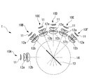
- the illumination device 1 is, as shown in FIG. 1, one of six light sources 10A, 10B, 10C, 10D, 10E, 10F, and these light sources 10A, 10B, 10C, 10D, 10E, 10F.
- Light from the other light source and a dichroic mirror (optical element) 13 for reflecting light from other light sources, and a rotation mechanism (optical element rotation means for rotating the dichroic mirror 13 about the rotation axis of the dichroic mirror 13
- a control unit (not shown) for controlling the rotation angle of the dichroic mirror by the rotation mechanism.
- Each of the light sources 10A, 10B, 10C, 10D, 10E, and 10F includes a light emitting element 11 such as an LED and collimating lenses 12a and 12b for collimating light emitted from the light emitting element 11, respectively.
- the light sources 10B, 10C, 10D, 10E, and 10F are arrayed such that the optical axes cross at one point on the dichroic mirror 13, and are annularly arranged at equal intervals from the left side in FIG.
- the arrangement intervals of the light sources 10A, 10B, 10C, 10D, 10E and 10F do not necessarily have to be equal intervals, and the optical axis of the light emitted from each of the light sources 10A, 10B, 10C, 10D, 10E and 10F is one point It should just be arrange
- the light source includes the light emitting element 11 and the collimating lenses 12a and 12b.
- the present invention is not limited to such a configuration.
- the collimating lenses 12a and 12b are not provided. It can also be done.
- the light source 10A is disposed at the left end, and the light source 10D is disposed at a position forming an angle of 90 ° with the direction of the light path of the light source 10A.
- the light source 10B is disposed between the light source 10A and the light source 10D at a position inclined 45 ° from the light source 10A and the light source 10D around the rotation axis of the dichroic mirror 13.
- the light source 10C is disposed between the light source 10B and the light source 10D, at a position inclined by 22.5 ° from the light source 10B and the light source 10D, respectively, around the rotation axis of the dichroic mirror 13.
- the light source 10F is disposed at a position inclined 45 ° in a direction away from the light source 10A with reference to the light source 10D with the rotation axis of the dichroic mirror 13 as a center.
- the light source 10E is disposed between the light source 10D and the light source 10F, at a position tilted by 22.5 ° from the light source 10D and the light source 10F, respectively, around the rotation axis of the dichroic mirror 13.
- the light sources 10A, 10B, 10C, 10D, 10E, and 10F are arranged in an annular shape located on the same circumference, and arranged so that the optical paths of the light from the respective light sources intersect at the center of the annular ring. It is done.
- the light sources 10A, 10B, 10C, 10D, 10E and 10F emit light in different wavelength regions. Specifically, the light source 10A has a wavelength of 400 nm, the light source 10B has a wavelength of 550 nm, the light source 10C has a wavelength of 600 nm, 10D emits light of 650 nm, the light source 10E of 700 nm, and the light source 10F of 750 nm.
- the light sources 10B, 10C, 10D, 10E and 10F are annular and equally spaced in order of shorter wavelength range from the left side in FIG. Is located in
- the dichroic mirror 13 has so-called short path characteristics and is disposed at the centers of the light sources 10A, 10B, 10C, 10D, 10E and 10F arranged in an annular shape, that is, the respective light sources 10A, 10B, 10C, 10D, 10E and 10F. At a position where the optical paths intersect, the dichroic mirror 13 is disposed so as to rotate about its center.
- the dichroic mirror 13 transmits the light from the light source 10A, reflects the light from the light sources 10B, 10C, 10D, 10E and 10F, and causes the reflected light to enter the optical path of the light from the light source 10A.
- the dichroic mirror is disposed at 45 ° with respect to the optical axis, and emits combined light by emitting the incident light and the reflected light in the same direction.
- the light from the light source 10A is incident with the dichroic mirror 13 inclined at 45 ° to the light path of the light source 10A, and is 45 ° from the normal to the dichroic mirror 13.
- the dichroic mirror 13 has a short path characteristic, the light incident from the light source 10A must have a shorter wavelength than the light reflected by the dichroic mirror 13. In the case of a dichroic mirror having long pass characteristics, the opposite is true.
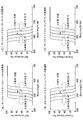
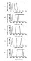
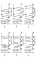
- FIG. 2 shows the optical characteristics of the dichroic mirror.
- the dichroic mirror shifts to the longer wavelength side as compared with the optical characteristics, that is, the reflectance characteristics and the transmittance characteristics at 45 °.
- the incident angle is deeper than 45 °, it shifts to the short wavelength side.
- the sum of the reflectance and transmittance of the dichroic mirror is about 100% except for the Fresnel loss in the dichroic mirror. That is, the sum of the reflectance in FIG. 2A and the transmittance in FIG. 2B is always about 100% at any wavelength.
- the dichroic mirror 13 has a short path characteristic, and the light source 10A is light passing through the dichroic mirror. Therefore, when the dichroic mirror is rotated clockwise about its rotation axis, the incident angle becomes shallow. Therefore, the transmission characteristics shift to the long wavelength side. Further, in the light sources 10B, 10C, 10D, 10E, and 10F arranged in an annular shape, the reflection characteristic is also shifted to the long wavelength side according to the rotation angle of the dichroic mirror 13. Therefore, if the wavelength of light reflected by the dichroic mirror 13 is lengthened as the clockwise rotation angle of the dichroic mirror 13 increases, efficient illumination can be performed without being affected by the oblique incident characteristics of the dichroic mirror. become. From such a reason, in the present embodiment, the light sources 10B, 10C, 10D, 10E, and 10F are arranged in an annular shape at equal intervals in the order of shorter wavelength regions from the left side in FIG.
- the rotation mechanism 14 rotates the dichroic mirror 13 by a predetermined rotation angle in the arrangement direction of the light sources 10A, 10B, 10C, 10D, 10E and 10F based on a control signal from the control unit described later, and tilts the dichroic mirror 13 Adjust.
- the rotation mechanism 14 can be configured, for example, using a motor or the like.
- the control unit adjusts the rotation angle of the dichroic mirror 13 so that the light from the light source 10B, 10C, 10D, 10E, and 10F enters the light path of the light from the light source 10A at the desired incident angle with respect to the rotation mechanism 14 Control signal is generated and output to the rotation mechanism 14. Thereby, the dichroic mirror 13 is controlled by the rotation mechanism 14 to a desired rotation angle. Further, the control unit controls lighting or extinguishing of the light sources 10A, 10B, 10C, 10D, 10E, and 10F.
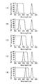
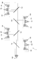
- FIG. , FIG. 4 and FIG. 5 a case where the light from the light source 10A and the light from the light sources 10B, 10C, 10D, 10E, and 10F are selected to generate and emit combined light is shown in FIG. , FIG. 4 and FIG. 5 will be described.
- FIG. 3A shows an example in the case of generating combined light of the light from the light source 10A and the light from the light source 10B.
- the dichroic mirror 13 is rotated by 22.5 ° counterclockwise around the rotation axis of the dichroic mirror 13 from the state of 45 ° inclining with respect to the direction of the light path of the light source 10A.
- the optical characteristics of the dichroic mirror 13 at this time are as shown in FIG. 4 (A) and FIG. 5 (A). Accordingly, the light from the light source 10A is transmitted through the dichroic mirror 13, and the light from the light source 10B is reflected by the dichroic mirror 13 to generate combined light.
- the combined light of the light from the light source 10A and the light from the light source 10F is generated.
- the dichroic mirror 13 is rotated 22.50 ° clockwise from the 45 ° inclined state.
- the optical characteristics of the dichroic mirror 13 are as shown in FIG. 4 (E) and FIG. 5 (E). Accordingly, the light source 10A transmits the dichroic mirror 13, and the light source 10F reflects the dichroic mirror 13 to generate combined light.
- the light from the light source 10A passes through the transmitted light path that passes straight through the dichroic mirror 13 while adjusting the rotation angle of the dichroic mirror 13 by the rotation mechanism 14 by the operation of the control unit
- the light from any of the other light sources 10B, 10C, 10D, 10E and 10F is reflected by the dichroic mirror 13 and enters the transmission light path of the light from the light source 10A.
- the rotation angle of the dichroic mirror 13 is switched by the rotation mechanism 14, it is possible to switch the light source for emitting the light to be incident on the transmission light path.
- light from three or more light sources 10A, 10B, 10C, 10D, 10E, and 10F can be made incident on one optical path by one dichroic mirror 13, and light loss during transmission or reflection of light can be reduced. It can be suppressed. Therefore, light of a plurality of different wavelengths can be appropriately selected, and the light guiding efficiency can be improved to emit light of higher luminance.
- This modification differs only in the characteristics of the illumination device and the dichroic mirror in the first embodiment described above. Therefore, the arrangement position and the like of the light source are the same as those of the above-described first embodiment, and therefore, will be described below with reference to FIG. That is, although what has a short pass characteristic was applied to dichroic mirror 13 in a 1st embodiment, a dichroic mirror having a long pass characteristic is applied in this modification. Therefore, as the light source 10A, the longest wavelength region among six light sources is applied.
- 750 nm, 400 nm, 450 nm, 500 nm, 550 nm, and 600 nm are applied to the light sources 10A, 10B, 10C, 10D, 10E, and 10F, respectively.
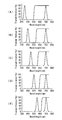
- FIG. 10 a case where light from the light source 10A and light from the light sources 10B, 10C, 10D, 10E, and 10F are selected to generate and emit combined light is shown in FIG. It demonstrates with reference to FIG.6 and FIG.7.
- FIG. 3A shows an example in the case of generating combined light of the light from the light source 10A and the light from the light source 10B.
- the dichroic mirror 13 is rotated by 22.5 degrees counterclockwise from the 45 ° inclined state.
- the optical characteristics of the dichroic mirror at this time are as shown in FIG. 6 (A) and FIG. 7 (A). Accordingly, the light from the light source 10A is transmitted through the dichroic mirror 13, and the light from the light source 10B is reflected by the dichroic mirror 13 to generate combined light.
- the dichroic mirror 13 is inclined at 45 °.
- the optical characteristics of the dichroic mirror 13 are as shown in FIG. 6 (C) and FIG. 7 (C). Accordingly, the light from the light source 10A is transmitted through the dichroic mirror, and the light from the light source 10D is reflected by the dichroic mirror to be color synthesized and illuminated.
- the combined light of the light from the light source 10A and the light from the light source 10F is generated.
- the dichroic mirror 13 is rotated 22.50 ° clockwise from the 45 ° inclined state.
- the optical characteristics of the dichroic mirror 13 are as shown in FIG. 6 (E) and FIG. 7 (E). Accordingly, the light source 10A transmits the dichroic mirror 13, and the light source 10F reflects the dichroic mirror 13 to generate combined light.
- the illumination device 2 which concerns on 2nd Embodiment is demonstrated with reference to drawings.
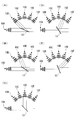
- the illumination device 2 according to the present embodiment includes a light source unit 17 having seven light sources, two dichroic mirrors 13a and 13b, and rotation mechanisms 14a and 14b for rotating the dichroic mirrors 13a and 13b. Have.
- the dichroic mirrors 13a and 13b are described as having short path characteristics.
- the light source unit 17 includes a light source 10A that emits light transmitted through the dichroic mirrors 13a and 13b, a light source group 17A (light sources 10B, 10C, and 10D) that emits light reflected by the dichroic mirrors 13a and 13b, and a light source group 17B (light sources 10E, 10F, 10G).
- the light sources 10B, 10C, and 10D constituting the light source group 17A are arranged in the same annular shape in the same circle, and are arranged such that the optical paths of the light from the respective light sources intersect at the center of this ring. ing.
- the light sources 10E, 10F, and 10G constituting the light source group 17B are also arranged in an annular shape located on the same circumference, so that the optical paths of light from the respective light sources intersect at the center of this annular ring. It is arranged.
- the light source 10A, the light source group 17A and the light source group 17B are arranged such that the intersection position of each light path of the light source group 17A and the intersection position of each light path of the light source group 17B are located on the optical path of light from the light source 10A. ing.
- the light source 10B emits light with a wavelength of 450 nm, and is disposed at an inclination of 67.5 ° in the optical path direction of the light source 10A with reference to the light source 10A.
- the light source 10C emits light of 500 nm and is disposed at an inclination of 90 ° in the optical path direction from the light source 10A.
- the light source 10D emits light having a wavelength of 550 nm, and is disposed so as to be inclined at 22.5 ° in the optical path direction of the light source 10A from the light source 10C.
- the light source 10E emits light with a wavelength of 600 nm, and is disposed at an inclination of 67.5 ° in the optical path direction of the light source 10A with reference to the light source 10A.
- the light source 10F emits light having a wavelength of 650 nm, and is arranged to be inclined by 90 ° in the optical path direction from the light source 10A.
- the light source 10G emits light having a wavelength of 700 nm, and is disposed so as to be inclined at 22.5 ° in the optical path direction of the light source 10A from the light source 10C.
- the dichroic mirror 13a is disposed at the intersection position of each light path of the light source group 17A, and the dichroic mirror 13b is disposed at the intersection position of each light path of the light source group 17B.
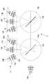
- FIG. 9 shows an example in the case of generating combined light of the light from the light source 10A and the light from the light source 10B and the light source 10F.
- the dichroic mirror 13a is rotated 11.25 ° counterclockwise from the 45 ° inclined state.
- the dichroic mirror 13 b is in a state of 45 ° inclination.
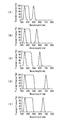
- the optical characteristics of the dichroic mirrors 13a and 13b are as shown in FIGS. 15 (A) and 16 (A). Accordingly, the light source 10A transmits the dichroic mirror 13a and then transmits the dichroic mirror 13b, and the light source 10B reflects the dichroic mirror 13a and then transmits the dichroic mirror 13b. Then, the light source 10F reflects the dichroic mirror 13b to generate combined light.
- FIG. 10 shows an example of generating combined light of the light from the light source 10A and the light from the light source 10C and the light source 10F.
- the dichroic mirrors 13a and 13b are both inclined at 45 °.
- the optical characteristics of the dichroic mirrors 13a and 13b are as shown in FIG. 15 (B) and FIG. 16 (B). Therefore, the light source 10A transmits the dichroic mirror 13a and then transmits the dichroic mirror 13b, and the light source 10C reflects the dichroic mirror 13a and then transmits the dichroic mirror 13b. Then, the light source 10F reflects the dichroic mirror 13b to generate combined light.
- FIG. 11 shows an example in the case of generating combined light of the light from the light source 10A and the light from the light source 10D and the light source 10F.
- the dichroic mirror 13a is rotated 11.25 ° clockwise from the 45 ° inclined state.
- the dichroic mirror 13 b is in a state of 45 ° inclination.
- the optical characteristics of the dichroic mirrors 13a and 13b are as shown in FIG. 15 (C) and FIG. 16 (C). Therefore, the light source 10A transmits the dichroic mirror 13a and then the dichroic mirror 13b, and the light source 10D reflects the dichroic mirror 13a and then transmits the dichroic mirror 13b. Then, the light source 10F reflects the dichroic mirror 13b to generate combined light.
- FIG. 12 shows an example of generating combined light of the light from the light source 10A and the light from the light source 10C and the light source 10E.
- the dichroic mirror 13a is in a 45 ° inclined state.
- the dichroic mirror 13 b is rotated 11.25 ° clockwise from the 45 ° inclined state.
- the optical characteristics of the dichroic mirrors 13a and 13b are as shown in FIG. 15 (D) and FIG. 16 (D). Therefore, the light source 10A transmits the dichroic mirror 13a and then the dichroic mirror 13b, and the light source 10D reflects the dichroic mirror 13a and then transmits the dichroic mirror 13b. Then, the light source 10E reflects the dichroic mirror 13b to generate combined light.
- FIG. 13 shows an example in the case of generating combined light of the light from the light source 10A and the light from the light source 10C and the light from the light source 10F.
- Both of the dichroic mirrors 13a and 13b are inclined 45 °.
- the optical characteristics of the dichroic mirrors 13a and 13b are as shown in FIG. 15 (E) and FIG. 16 (E). Accordingly, the light source 10A transmits the dichroic mirror 13a and then transmits the dichroic mirror 13b, and the light source 10F reflects the dichroic mirror 13a and then transmits the dichroic mirror 13b. Then, the light source 10E reflects the dichroic mirror 13b to generate combined light.
- FIG. 14 shows an example of generating combined light of the light from the light source 10A and the light from the light source 10C and the light from the light source 10G.
- the dichroic mirror 13a is in a 45 ° inclined state.
- the dichroic mirror 13 b is rotated 11.25 ° clockwise from the 45 ° inclined state.
- the optical characteristics of the dichroic mirrors 13a and 13b are as shown in FIG. 15 (F) and FIG. 16 (F). Therefore, the light source 10A transmits the dichroic mirror 13a and then transmits the dichroic mirror 13b, and the light source 10C reflects the dichroic mirror 13a and then transmits the dichroic mirror 13b. Then, the light source 10G reflects the dichroic mirror 13b to generate combined light.
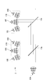
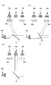
- the illumination device 3 according to the present modification includes a light source unit including four light source groups, four dichroic mirrors 13a, 13b, 13c, 13d, and these dichroic mirrors 13a, 13b, 13c, It has rotation mechanisms 14a and 14b for rotating 13d.
- the dichroic mirrors 13a, 13b, 13c, and 13d are described as having short path characteristics.
- the light source unit of the illumination device 3 includes the light source 10A and the light source groups 17A, 17B, 17C, and 17D, and the light sources constituting the light source groups 17A, 17B, 17C, and 17D are respectively disposed in an annular shape.
- the center of the light source group 17A, 17B, 17C, 17D is the cross point of the light from each light source.
- the light source 10A and the light source groups 17A, 17B, 17C, 17D are positioned such that the intersection position of each light path from the light sources constituting the light source groups 17A, 17B, 17C, 17D is located on the light path of light from the light source 10A. Is arranged.
- the dichroic mirrors 13a, 13b, 13c and 13d are positioned at the respective intersection positions.
- the light source 10A that emits light with a wavelength of 400 nm is disposed at the left end.
- the light source group 17A has the light sources 10B, 10C, and 10D disposed in an annular shape centered on the position of the dichroic mirror 13a, and the light source 10B is in the light path direction of the light source 10A with reference to the light source 10A in FIG. It is placed at an inclination of 67.5 ° clockwise.
- the light source 10C is inclined by 22.5 ° clockwise in the light path direction of the light source 10A from the light source 10B, and the light source 10D is arranged by 22.5 ° clockwise in the light path direction of the light source 10A from the light source 10C.
- the light source 10B emits light with a wavelength of 430 nm
- the light source 10C emits light with a wavelength of 460 nm
- the light source 10D emits light with a wavelength of 490 nm.
- the light source group 17B has the light sources 10E, 10F, and 10G disposed in an annular shape centered on the position of the dichroic mirror 13b, and the light source 10E is the light source 10A of FIG. It is disposed at an inclination of 67.5 ° counterclockwise in the light path direction.
- the light source 10F is inclined 22.5 ° counterclockwise from the light source 10E toward the light path of the light source 10A
- the light source 10G is inclined 22.5 ° counterclockwise from the light source 10F toward the light path from the light source 10A. It is arranged.
- the light source 10E emits light of wavelength 520 nm
- the light source 10F emits light of wavelength 550 nm
- the light source 10G emits light of wavelength 580 nm.
- the light source group 17C has the light sources 10H, 10I and 10J arranged in a ring shape centering on the position of the dichroic mirror 13c, and the light source 10H is in the light path direction of the light source 10A with reference to the light source 10A in FIG. It is placed at an inclination of 67.5 ° clockwise.
- the light source 10I is inclined by 22.5 ° clockwise in the light path direction of the light source 10A from the light source 10H
- the light source 10J is disposed by 22.5 ° clockwise in the light path direction of the light source 10A from the light source 10H. ing.
- the light source 10H emits light having a wavelength of 610 nm
- the light source 10I emits light having a wavelength of 640 nm
- the light source 10J emits light having a wavelength of 670 nm.
- the light source group 17D has the light sources 10K, 10L and 10M arranged in an annular shape centering on the position of the dichroic mirror 13d, and the light source 10K is in the light path direction of the light source 10A with reference to the light source 10A in FIG. It is placed counterclockwise at 67.5 °.
- the light source 10L is inclined 22.5 ° counterclockwise from the light source 10K toward the light path of the light source 10A
- the light source 10M is inclined 22.5 ° counterclockwise from the light source 10L toward the light path from the light source 10L. It is arranged.
- the light source 10K emits light having a wavelength of 700 nm
- the light source 10L emits light having a wavelength of 730 nm
- the light source 10M emits light having a wavelength of 760 nm.
- the illumination device 4 according to the third embodiment will be described below with reference to the drawings.
- the light sources are not arranged in an annular shape as in the above-described embodiments, and the light sources 10B, 10C, and 10D are linearly arranged.
- the light source 10A emitting the light of 400 nm transmitting the dichroic mirror 13 having short path characteristics is disposed at the left end, and the light sources 10B, 10C, and 10D are disposed at positions orthogonal to the light path of the light source 10A. It is arranged at equal intervals.
- the light source 10B and the light source 10D have the prisms 16b and 16d as optical path changing members, the light from the light source 10B is the same as the light path of the light from the light source 10C by the prism 16b and the light from the light source 10D by the prism 16d. It is supposed to cross at the position. Then, the intersection position is on the light path of the light from the light source 10A.
- the light source 10B emits light with a wavelength of 450 nm
- the light source 10C emits light with a wavelength of 500 nm
- the light source 10D emits light with a wavelength of 550 nm.
- the illumination device 4 configured as described above, for example, a case where the light from the light source 10A and the light from the light sources 10B, 10C, and 10D are selected to generate and emit combined light will be described with reference to FIG. explain.
- the light from the light source 10B and the light source 10D is inclined by 22.5 ° with respect to the light from the light source 10C and enters the dichroic mirror 13 by the prisms 16b and 16d.
- FIG. 19A shows an example of generating combined light of the light from the light source 10A and the light from the light source 10B.
- the dichroic mirror 13 is rotated by 22.5 degrees counterclockwise from the 45 ° inclined state.
- the optical characteristics of the dichroic mirror at this time are as shown in FIG. 15 (A) and FIG. 16 (A). Accordingly, the light from the light source 10A is transmitted through the dichroic mirror 13, and the light from the light source 10B is reflected by the dichroic mirror 13 to generate combined light.
- the dichroic mirror 13 is inclined at 45 °.
- the optical characteristics of the dichroic mirror 13 are as shown in FIG. 15 (C) and FIG. 16 (C). Accordingly, the light from the light source 10A is transmitted through the dichroic mirror, and the light from the light source 10D is reflected by the dichroic mirror to be color synthesized and illuminated.
- each light source is disposed on a straight line, and two light source groups each including three light sources disposed on the straight line are provided.
- the light source 10A for emitting light of 400 nm that transmits the dichroic mirrors 13a and 13b having short path characteristics is disposed at the left end, and is orthogonal to the light path of the light source 10A.
- a light source group 17A consisting of 10D and a light source group 17B consisting of light sources 10E, 10F, 10G are arranged at equal intervals.
- the light source 10B and the light sources 10D, 10E and 10G have prisms 16b, 16d, 16e and 16f as light path changing members, the light from the light source 10B is by the prism 16b and the light from the light source 10D is by the prism 16d It intersects at the same position as the optical path of light from 10C. Similarly, the light from the light source 10E is crossed by the prism 16e, and the light from the light source 10G is crossed by the prism 16g at the same position as the light path of the light from the light source 10C. And each intersection position becomes an optical path of the light from light source 10A.
- LED was applied as a light emitting element, it is not restricted to this, for example, LD, a lamp, etc. are applicable.
- dichroic mirror was applied as an optical element, it is not restricted to this, For example, a dichroic prism etc. can also be applied.
- various arrangements of light sources can be made by rotatably providing the dichroic mirror.
- the light from the light source 10A passes through the transmitted light path that passes straight through the dichroic mirror 13, while adjusting the rotation angle of the dichroic mirror 13 by the rotation mechanism, any of the other light sources 10B, 10C, 10D, etc.
- the light from the light source 10 is reflected by the dichroic mirror 13 and enters the transmission light path of the light from the light source 10A.
- the rotation angle of the dichroic mirror 13 is switched by the rotation mechanism 14, it is possible to switch the light source for emitting the light to be incident on the transmission light path. That is, light from three or more light sources 10A, 10B, 10C, 10D, etc.
Abstract
To radiate light having higher luminance by selecting light having a plurality of different wavelengths as needed, and by improving light guide efficiency. Provided is an illuminating apparatus (1), which is provided with: three or more light sources (10A, 10B, 10C, 10D, 10E, 10F), which are disposed with optical axes thereof intersecting at one point, and which output light in different wavelength regions; an optical element (13), which passes through light emitted from one light source among the light sources, reflects light emitted from other light sources, and makes the light enter an optical path of the light emitted from the one light source; and an optical element rotating means (14), which rotates the optical element in the direction in which the light sources are disposed.
Description
本発明は、照明装置に関するものである。
The present invention relates to a lighting device.
従来、顕微鏡装置において、蛍光試薬を塗布した観察対象に特定波長の光を照射して蛍光試薬を励起させることにより観察対象から発せられる蛍光を検出して観察したり、内視鏡装置において、観察対象に特定波長の光を照射することにより生体から発せられる蛍光を検出して観察したりする、所謂蛍光観察が広く行われている。
蛍光観察において、観察対象から効率よく蛍光を検出するためには、蛍光試薬または生体の励起光特性に応じた波長の光を照射する必要がある。励起光特性は蛍光試薬毎又は生体によって異なるため、顕微鏡装置や内視鏡装置に適用される照明装置は、多様な励起光特性に応じて複数の異なる波長の光を照明することができるようになっている。
このような照明装置の例として、特許文献1には、3つの光源(LED)と2つのダイクロイックミラーとを備え、各光源を適宜切り替え、ダイクロイックミラーにより複数の波長の光を色合成することにより、観察対象に照射する光の波長を選択して出力することができるものが記載されている。 Conventionally, in a microscope apparatus, light of a specific wavelength is irradiated to an observation target coated with a fluorescent reagent to excite the fluorescent reagent, thereby detecting and observing fluorescence emitted from the observation target, or observing with an endoscope apparatus So-called fluorescence observation in which fluorescence emitted from a living body is detected and observed by irradiating a subject with light of a specific wavelength is widely performed.
In fluorescence observation, in order to detect fluorescence from an observation object efficiently, it is necessary to irradiate light of a wavelength according to the excitation light characteristic of a fluorescence reagent or a living body. Since the excitation light characteristics are different for each fluorescent reagent or the living body, the illumination device applied to the microscope apparatus or the endoscope apparatus can illuminate light of a plurality of different wavelengths according to various excitation light characteristics. It has become.
As an example of such an illumination device,Patent Document 1 includes three light sources (LEDs) and two dichroic mirrors, appropriately switching each light source, and color combining light of a plurality of wavelengths with the dichroic mirrors. What can select and output the wavelength of the light irradiated to observation object is described.
蛍光観察において、観察対象から効率よく蛍光を検出するためには、蛍光試薬または生体の励起光特性に応じた波長の光を照射する必要がある。励起光特性は蛍光試薬毎又は生体によって異なるため、顕微鏡装置や内視鏡装置に適用される照明装置は、多様な励起光特性に応じて複数の異なる波長の光を照明することができるようになっている。
このような照明装置の例として、特許文献1には、3つの光源(LED)と2つのダイクロイックミラーとを備え、各光源を適宜切り替え、ダイクロイックミラーにより複数の波長の光を色合成することにより、観察対象に照射する光の波長を選択して出力することができるものが記載されている。 Conventionally, in a microscope apparatus, light of a specific wavelength is irradiated to an observation target coated with a fluorescent reagent to excite the fluorescent reagent, thereby detecting and observing fluorescence emitted from the observation target, or observing with an endoscope apparatus So-called fluorescence observation in which fluorescence emitted from a living body is detected and observed by irradiating a subject with light of a specific wavelength is widely performed.
In fluorescence observation, in order to detect fluorescence from an observation object efficiently, it is necessary to irradiate light of a wavelength according to the excitation light characteristic of a fluorescence reagent or a living body. Since the excitation light characteristics are different for each fluorescent reagent or the living body, the illumination device applied to the microscope apparatus or the endoscope apparatus can illuminate light of a plurality of different wavelengths according to various excitation light characteristics. It has become.
As an example of such an illumination device,
しかしながら、特許文献1の照明装置では、複数の波長の光を色合成するために複数のダイクロイックミラーを使用している。より具体的には、光源の数よりも一つ少ない数のダイクロイックミラーを配置している。このため、少なくとも一つの光源から出射された光は、光源の数よりも一つ少ない数のダイクロイックミラーを透過しなければならない。従って、光源から出射された光は、ダイクロイックミラーを通過する毎に光量を損失するため、導光効率が低く、観察対象において十分な光量を得ることができない。
However, in the illumination device of Patent Document 1, a plurality of dichroic mirrors are used to color combine light of a plurality of wavelengths. More specifically, the number of dichroic mirrors which is smaller by one than the number of light sources is disposed. For this reason, the light emitted from at least one light source has to transmit the number of dichroic mirrors which is one less than the number of light sources. Therefore, the light emitted from the light source loses light quantity every time it passes through the dichroic mirror, so the light guiding efficiency is low, and a sufficient light quantity can not be obtained in the observation object.
本発明は、このような事情に鑑みてなされたものであって、異なる複数波長の光を適宜選択し、かつ、導光効率を向上させてより高輝度の光を照射することができる照明装置を提供することを目的とする。
This invention is made in view of such a situation, Comprising: The light of a several different wavelength is selected suitably, And a light-guide efficiency can be improved and the illuminating device which can irradiate the light of higher brightness. Intended to provide.
上記課題を解決するために、本発明は以下の手段を採用する。
本発明の一態様は、光軸を一点で交差させて配列され夫々異なる波長領域の光を出射する3つ以上の光源と、該光源のうち一の光源からの光を透過すると共に、他の光源からの光を反射して、前記一の光源からの光の光路に入射させる光学素子と、該光学素子を前記光源の配列方向に回転させる光学素子回転手段とを備える照明装置を提供する。 In order to solve the above-mentioned subject, the present invention adopts the following means.
According to one aspect of the present invention, three or more light sources arranged such that optical axes are crossed at one point and which emit light of different wavelength regions, light from one of the light sources is transmitted, and An illumination device is provided, comprising: an optical element that reflects light from a light source and enters an optical path of light from the one light source; and an optical element rotation unit that rotates the optical element in the arrangement direction of the light source.
本態様によれば、一の光源からの光は、光学素子を透過して直進する透過光路を通過する。一方、制御手段の作動により、光学素子回転手段による光学素子の回転角を調節すると、他の一の光源からの光が、光学素子により反射されて、前記透過光路に入射する。光学素子回転手段によって光学素子の回転角を切り替えると、透過光路に入射させる光を射出する光源を切り替えることができる。すなわち、単一の光学素子により3つ以上の光源からの光を同一の光路に入射させることができ、光の透過又は反射の際の光の損失を抑制することができる。従って、異なる複数波長の光を適宜選択し、かつ、導光効率を向上させてより高輝度の光を照射することができる。
なお、光学素子回転手段による光学素子の回転角を制御する制御手段を設けることで、光学素子の回転角を所望の角度に適宜調節することができる。 According to this aspect, the light from the one light source passes through the transmitted light path that passes straight through the optical element. On the other hand, when the rotation angle of the optical element by the optical element rotation means is adjusted by the operation of the control means, the light from the other light source is reflected by the optical element and enters the transmitted light path. When the rotation angle of the optical element is switched by the optical element rotation means, it is possible to switch the light source for emitting the light to be incident on the transmission light path. That is, light from three or more light sources can be incident on the same optical path by a single optical element, and light loss can be suppressed when transmitting or reflecting light. Therefore, light of a plurality of different wavelengths can be appropriately selected, and the light guiding efficiency can be improved to emit light of higher luminance.
In addition, the rotation angle of an optical element can be suitably adjusted to a desired angle by providing the control means which controls the rotation angle of an optical element by an optical element rotation means.
上記した態様においては、複数の前記光源が円環状に配置され、該円環状に配置された複数の光源の中心に前記光学素子が配置されたことが好ましい。
このようにすることで、光学素子に対する各光源の距離が等しくなるので、光学素子の回転角を容易に制御することができる。 In the aspect described above, it is preferable that the plurality of light sources be disposed in an annular shape, and the optical element be disposed at the center of the plurality of light sources disposed in the annular shape.
By doing this, the distances of the light sources to the optical element become equal, so that the rotation angle of the optical element can be easily controlled.
上記した態様においては、複数の前記光源が等間隔に配置されていることが好ましい。
このようにすることで、光学素子に対する各光源の位置を容易に把握することができるので、光学素子の回転角を容易に制御することができる。 In the aspect described above, it is preferable that the plurality of light sources be arranged at equal intervals.
By doing so, the position of each light source with respect to the optical element can be easily grasped, so that the rotation angle of the optical element can be easily controlled.
本発明によれば、異なる複数波長の光を適宜選択し、かつ、導光効率を向上させてより高輝度の光を照射することができるという効果を奏する。
According to the present invention, it is possible to appropriately select light of a plurality of different wavelengths, improve light guiding efficiency, and irradiate light of higher luminance.
(第1の実施形態)
以下、第1の実施形態に係る照明装置1について、図面を参照して説明する。
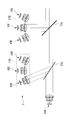
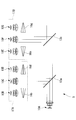
本実施形態に係る照明装置1は、図1に示すように、6つの光源10A,10B,10C,10D,10E,10Fと、これらの光源10A,10B,10C,10D,10E,10Fのうち一の光源からの光を透過すると共に、他の光源からの光を反射するダイクロイックミラー(光学素子)13と、ダイクロイックミラー13をダイクロイックミラー13の回転軸を中心に回転させる回転機構(光学素子回転手段)14と、回転機構14によるダイクロイックミラーの回転角を制御する制御部(図示せず)とを備えている。 First Embodiment
Hereinafter, theillumination device 1 according to the first embodiment will be described with reference to the drawings.
Theillumination device 1 according to the present embodiment is, as shown in FIG. 1, one of six light sources 10A, 10B, 10C, 10D, 10E, 10F, and these light sources 10A, 10B, 10C, 10D, 10E, 10F. Light from the other light source, and a dichroic mirror (optical element) 13 for reflecting light from other light sources, and a rotation mechanism (optical element rotation means for rotating the dichroic mirror 13 about the rotation axis of the dichroic mirror 13 And a control unit (not shown) for controlling the rotation angle of the dichroic mirror by the rotation mechanism.
以下、第1の実施形態に係る照明装置1について、図面を参照して説明する。
本実施形態に係る照明装置1は、図1に示すように、6つの光源10A,10B,10C,10D,10E,10Fと、これらの光源10A,10B,10C,10D,10E,10Fのうち一の光源からの光を透過すると共に、他の光源からの光を反射するダイクロイックミラー(光学素子)13と、ダイクロイックミラー13をダイクロイックミラー13の回転軸を中心に回転させる回転機構(光学素子回転手段)14と、回転機構14によるダイクロイックミラーの回転角を制御する制御部(図示せず)とを備えている。 First Embodiment
Hereinafter, the
The
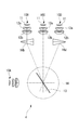
光源10A,10B,10C,10D,10E,10Fは、夫々LED等の発光素子11及び発光素子11から射出された光を平行化するコリメートレンズ12a,12bを備えている。光源10B,10C,10D,10E,10Fは、光軸をダイクロイックミラー13上の一点で交差させて配列され、図1中左側から、円環状にかつ等間隔に配置されている。
なお、光源10A,10B,10C,10D,10E,10Fの配置間隔は必ずしも等間隔である必要はなく、各光源10A,10B,10C,10D,10E,10Fから射出される光の光軸が一点で交差するように配置されていればよい。また、本実施形態においては、光源が発光素子11とコリメートレンズ12a,12bとを備える構成としたが、このような構成に限定されるものではなく、例えば、コリメートレンズ12a,12bを設けない構成とすることもできる。 Each of the light sources 10A, 10B, 10C, 10D, 10E, and 10F includes a light emitting element 11 such as an LED and collimating lenses 12a and 12b for collimating light emitted from the light emitting element 11, respectively. The light sources 10B, 10C, 10D, 10E, and 10F are arrayed such that the optical axes cross at one point on the dichroic mirror 13, and are annularly arranged at equal intervals from the left side in FIG.
The arrangement intervals of the light sources 10A, 10B, 10C, 10D, 10E and 10F do not necessarily have to be equal intervals, and the optical axis of the light emitted from each of the light sources 10A, 10B, 10C, 10D, 10E and 10F is one point It should just be arrange | positioned so that it may cross. In the present embodiment, the light source includes the light emitting element 11 and the collimating lenses 12a and 12b. However, the present invention is not limited to such a configuration. For example, the collimating lenses 12a and 12b are not provided. It can also be done.
なお、光源10A,10B,10C,10D,10E,10Fの配置間隔は必ずしも等間隔である必要はなく、各光源10A,10B,10C,10D,10E,10Fから射出される光の光軸が一点で交差するように配置されていればよい。また、本実施形態においては、光源が発光素子11とコリメートレンズ12a,12bとを備える構成としたが、このような構成に限定されるものではなく、例えば、コリメートレンズ12a,12bを設けない構成とすることもできる。 Each of the
The arrangement intervals of the
すなわち、図1中、光源10Aを左端に配置し、光源10Aの光路の方向と90°の角度をなす位置に光源10Dを配置する。光源10Bは光源10A及び光源10Dの間であって、ダイクロイックミラー13の回転軸を中心に、光源10A及び光源10Dから夫々45°傾斜した位置に配置する。さらに、光源10Cは光源10B及び光源10Dの間であって、ダイクロイックミラー13の回転軸を中心に、光源10B及び光源10Dから夫々22.5°傾斜した位置に配置する。また、光源10Fは、ダイクロイックミラー13の回転軸を中心に、光源10Dを基準に光源10Aから遠ざかる方向に45°傾斜した位置に配置する。さらに、光源10Eは、光源10D及び光源10Fの間であって、ダイクロイックミラー13の回転軸を中心に、光源10D及び光源10Fから夫々22.5°傾斜した位置に配置する。
各光源10A,10B,10C,10D,10E,10Fは、同一の円周上に位置する円環状に配置されており、この円環の中心で各光源からの光の光路が交差するように配置されている。 That is, in FIG. 1, thelight source 10A is disposed at the left end, and the light source 10D is disposed at a position forming an angle of 90 ° with the direction of the light path of the light source 10A. The light source 10B is disposed between the light source 10A and the light source 10D at a position inclined 45 ° from the light source 10A and the light source 10D around the rotation axis of the dichroic mirror 13. Further, the light source 10C is disposed between the light source 10B and the light source 10D, at a position inclined by 22.5 ° from the light source 10B and the light source 10D, respectively, around the rotation axis of the dichroic mirror 13. Further, the light source 10F is disposed at a position inclined 45 ° in a direction away from the light source 10A with reference to the light source 10D with the rotation axis of the dichroic mirror 13 as a center. Furthermore, the light source 10E is disposed between the light source 10D and the light source 10F, at a position tilted by 22.5 ° from the light source 10D and the light source 10F, respectively, around the rotation axis of the dichroic mirror 13.
The light sources 10A, 10B, 10C, 10D, 10E, and 10F are arranged in an annular shape located on the same circumference, and arranged so that the optical paths of the light from the respective light sources intersect at the center of the annular ring. It is done.
各光源10A,10B,10C,10D,10E,10Fは、同一の円周上に位置する円環状に配置されており、この円環の中心で各光源からの光の光路が交差するように配置されている。 That is, in FIG. 1, the
The
また、光源10A,10B,10C,10D,10E,10Fは、夫々異なる波長領域の光を出射するものであり、具体的には、光源10Aは400nm、光源10Bは550nm、光源10Cは600nm、光源10Dは650nm、光源10Eは700nm、光源10Fは750nm、の光を夫々出射する。本実施形態においては、後述するダイクロイックミラー13が所謂ショートパス特性を有することから、光源10B,10C,10D,10E,10Fは、図1中左側から、波長領域が短い順に円環状にかつ等間隔に配置されている。
The light sources 10A, 10B, 10C, 10D, 10E and 10F emit light in different wavelength regions. Specifically, the light source 10A has a wavelength of 400 nm, the light source 10B has a wavelength of 550 nm, the light source 10C has a wavelength of 600 nm, 10D emits light of 650 nm, the light source 10E of 700 nm, and the light source 10F of 750 nm. In the present embodiment, since the dichroic mirror 13 to be described later has a so-called short path characteristic, the light sources 10B, 10C, 10D, 10E and 10F are annular and equally spaced in order of shorter wavelength range from the left side in FIG. Is located in
ダイクロイックミラー13は、所謂ショートパス特性を有し、円環状に配置された光源10A,10B,10C,10D,10E,10Fの中心に、すなわち各光源10A,10B,10C,10D,10E,10Fの光路が交差する位置に、ダイクロイックミラー13の中心を軸に回転するように配置されている。ダイクロイックミラー13は、光源10Aからの光を透過すると共に、光源10B,10C,10D,10E,10Fからの光を反射して、反射した光を光源10Aからの光の光路に入射させる。
The dichroic mirror 13 has so-called short path characteristics and is disposed at the centers of the light sources 10A, 10B, 10C, 10D, 10E and 10F arranged in an annular shape, that is, the respective light sources 10A, 10B, 10C, 10D, 10E and 10F. At a position where the optical paths intersect, the dichroic mirror 13 is disposed so as to rotate about its center. The dichroic mirror 13 transmits the light from the light source 10A, reflects the light from the light sources 10B, 10C, 10D, 10E and 10F, and causes the reflected light to enter the optical path of the light from the light source 10A.
ここで、一般に、ダイクロイックミラーは、光軸に対して45°に配置して、入射光と反射光が同じ方向になるように射出することにより合成光を生成する。図1では、光源10Aからの光は、ダイクロイックミラー13が光源10Aの光路に対して45°に傾斜した状態で入射され、ダイクロイックミラー13の法線から45°となるため、入射角45°となる。ダイクロイックミラー13がショートパス特性を有する場合には、光源10Aから入射された光は、ダイクロイックミラー13で反射される光よりも波長は短くなければならない。ロングパス特性を有するダイクロイックミラーの場合にはその反対となる。
Here, in general, the dichroic mirror is disposed at 45 ° with respect to the optical axis, and emits combined light by emitting the incident light and the reflected light in the same direction. In FIG. 1, the light from the light source 10A is incident with the dichroic mirror 13 inclined at 45 ° to the light path of the light source 10A, and is 45 ° from the normal to the dichroic mirror 13. Become. When the dichroic mirror 13 has a short path characteristic, the light incident from the light source 10A must have a shorter wavelength than the light reflected by the dichroic mirror 13. In the case of a dichroic mirror having long pass characteristics, the opposite is true.
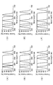
また、ダイクロイックミラーは、入射角によって、反射、透過特性のシフトするものであり、図2に、ダイクロイックミラーの光学特性を示した。図2に示すように、ダイクロイックミラーは、入射角度が45°よりも浅くなると、その光学特性、すなわち、反射率特性及び透過率特性が共に45°のときより長波長側にシフトする。反対に、入射角度が45°よりも深くなると短波長側にシフトする。ダイクロイックミラーの反射率と透過率の和は、ダイクロイックミラーにおけるFresnel損出を除ければ、約100%となる。つまり、図2(A)の反射率と図2(B)の透過率の和は、どの波長においても常に約100%となる。
The dichroic mirror shifts the reflection and transmission characteristics depending on the incident angle. FIG. 2 shows the optical characteristics of the dichroic mirror. As shown in FIG. 2, when the incident angle becomes smaller than 45 °, the dichroic mirror shifts to the longer wavelength side as compared with the optical characteristics, that is, the reflectance characteristics and the transmittance characteristics at 45 °. On the contrary, when the incident angle is deeper than 45 °, it shifts to the short wavelength side. The sum of the reflectance and transmittance of the dichroic mirror is about 100% except for the Fresnel loss in the dichroic mirror. That is, the sum of the reflectance in FIG. 2A and the transmittance in FIG. 2B is always about 100% at any wavelength.
本実施形態において、ダイクロイックミラー13はショートパス特性を有し、光源10Aは、ダイクロイックミラーを透過する光であるので、ダイクロイックミラーをその回転軸を中心に時計周りに回転すると、入射角度が浅くなるため、透過特性は長波長側へシフトする。また、円環状に配置された光源10B,10C,10D,10E,10Fでは、ダイクロイックミラー13の回転角度に応じて、反射特性も長波長側へシフトする。従って、ダイクロイックミラー13の時計周りへの回転角度が大きくなるにつれ、ダイクロイックミラー13で反射する光の波長を長くすると、ダイクロイックミラーの斜入射特性の影響を受けることなく、効率よく照明することが可能になる。このような理由から、本実施形態においては、光源10B,10C,10D,10E,10Fを図1中左側から、波長領域が短い順に円環状にかつ等間隔に配置している。
In the present embodiment, the dichroic mirror 13 has a short path characteristic, and the light source 10A is light passing through the dichroic mirror. Therefore, when the dichroic mirror is rotated clockwise about its rotation axis, the incident angle becomes shallow. Therefore, the transmission characteristics shift to the long wavelength side. Further, in the light sources 10B, 10C, 10D, 10E, and 10F arranged in an annular shape, the reflection characteristic is also shifted to the long wavelength side according to the rotation angle of the dichroic mirror 13. Therefore, if the wavelength of light reflected by the dichroic mirror 13 is lengthened as the clockwise rotation angle of the dichroic mirror 13 increases, efficient illumination can be performed without being affected by the oblique incident characteristics of the dichroic mirror. become. From such a reason, in the present embodiment, the light sources 10B, 10C, 10D, 10E, and 10F are arranged in an annular shape at equal intervals in the order of shorter wavelength regions from the left side in FIG.
なお、ダイクロイックミラー13がロングパス特性を有するときも、光源10B,10C,10D,10E,10Fの位置を変えることにより透過光と反射光の導光効率を下げることなく、色合成して照明することが可能となる。
Even when the dichroic mirror 13 has a long pass characteristic, color combination is performed without changing the positions of the light sources 10B, 10C, 10D, 10E, and 10F without reducing the light guiding efficiency of the transmitted light and the reflected light. Is possible.
回転機構14は、後述する制御部からの制御信号に基づいてダイクロイックミラー13を光源10A,10B,10C,10D,10E,10Fの配列方向に所定の回転角だけ回転させ、ダイクロイックミラー13の傾きを調節する。回転機構14は、例えば、モーター等を用いて構成することができる。
制御部は、回転機構14に対して光源10B,10C,10D,10E,10Fからの光を所望の入射角で、光源10Aからの光の光路に入射させるようにダイクロイックミラー13の回転角を調節するための制御信号を生成し、回転機構14に出力する。これにより、回転機構14によってダイクロイックミラー13が所望の回転角に制御される。また、制御部は、光源10A,10B,10C,10D,10E,10Fの点灯又は消灯を制御する。 Therotation mechanism 14 rotates the dichroic mirror 13 by a predetermined rotation angle in the arrangement direction of the light sources 10A, 10B, 10C, 10D, 10E and 10F based on a control signal from the control unit described later, and tilts the dichroic mirror 13 Adjust. The rotation mechanism 14 can be configured, for example, using a motor or the like.
The control unit adjusts the rotation angle of thedichroic mirror 13 so that the light from the light source 10B, 10C, 10D, 10E, and 10F enters the light path of the light from the light source 10A at the desired incident angle with respect to the rotation mechanism 14 Control signal is generated and output to the rotation mechanism 14. Thereby, the dichroic mirror 13 is controlled by the rotation mechanism 14 to a desired rotation angle. Further, the control unit controls lighting or extinguishing of the light sources 10A, 10B, 10C, 10D, 10E, and 10F.
制御部は、回転機構14に対して光源10B,10C,10D,10E,10Fからの光を所望の入射角で、光源10Aからの光の光路に入射させるようにダイクロイックミラー13の回転角を調節するための制御信号を生成し、回転機構14に出力する。これにより、回転機構14によってダイクロイックミラー13が所望の回転角に制御される。また、制御部は、光源10A,10B,10C,10D,10E,10Fの点灯又は消灯を制御する。 The
The control unit adjusts the rotation angle of the
以下、このように構成された照明装置1において、例えば光源10Aからの光と、光源10B,10C,10D,10E,10Fからの光を選択して合成光を生成して照射する場合について図3、図4及び図5を参照して説明する。
Hereinafter, in the illumination device 1 configured as described above, for example, a case where the light from the light source 10A and the light from the light sources 10B, 10C, 10D, 10E, and 10F are selected to generate and emit combined light is shown in FIG. , FIG. 4 and FIG. 5 will be described.
図3(A)に、光源10Aからの光と光源10Bからの光の合成光を生成する場合の例を示した。ダイクロイックミラー13は光源10Aの光路の方向に対し45°傾斜の状態から、ダイクロイックミラー13の回転軸を中心に、反時計周りに22.5°回転した状態である。この時のダイクロイックミラー13の光学特性は、図4(A)、図5(A)となる。従って、光源10Aからの光はダイクロイックミラー13を透過し、光源10Bからの光はダイクロイックミラー13を反射して、合成光が生成される。
FIG. 3A shows an example in the case of generating combined light of the light from the light source 10A and the light from the light source 10B. The dichroic mirror 13 is rotated by 22.5 ° counterclockwise around the rotation axis of the dichroic mirror 13 from the state of 45 ° inclining with respect to the direction of the light path of the light source 10A. The optical characteristics of the dichroic mirror 13 at this time are as shown in FIG. 4 (A) and FIG. 5 (A). Accordingly, the light from the light source 10A is transmitted through the dichroic mirror 13, and the light from the light source 10B is reflected by the dichroic mirror 13 to generate combined light.
図3(B)に示す例では、光源10Aからの光と光源10Cからの光の合成光を生成する。ダイクロイックミラー13は45°傾斜の状態から反時計周りに11.25°回転した状態である。この時の、ダイクロイックミラー13の光学特性は、図4(B)及び図5(B)となる。従って、光源10Aからの光はダイクロイックミラー13を透過し、光源10Cからの光はダイクロイックミラー13を反射して、合成光が生成される。
In the example shown in FIG. 3B, combined light of the light from the light source 10A and the light from the light source 10C is generated. The dichroic mirror 13 is rotated 11.25 ° counterclockwise from the 45 ° inclined state. The optical characteristics of the dichroic mirror 13 at this time are as shown in FIG. 4 (B) and FIG. 5 (B). Accordingly, the light from the light source 10A is transmitted through the dichroic mirror 13, and the light from the light source 10C is reflected by the dichroic mirror 13 to generate combined light.
図3(C)に示す例では、光源10Aからの光と光源10Dからの光の合成光を生成する。ダイクロイックミラー13は45°傾斜の状態である。ダイクロイックミラー13の光学特性は、図4(C)及び図5(C)となる。従って、光源10Aからの光はダイクロイックミラー13を透過し、光源10Dからの光はダイクロイックミラー13を反射して、合成光が生成される。
In the example shown in FIG. 3C, combined light of the light from the light source 10A and the light from the light source 10D is generated. The dichroic mirror 13 is inclined at 45 °. The optical characteristics of the dichroic mirror 13 are as shown in FIG. 4 (C) and FIG. 5 (C). Accordingly, the light from the light source 10A is transmitted through the dichroic mirror 13, and the light from the light source 10D is reflected by the dichroic mirror 13 to generate combined light.
図3(D)に示す例では、光源10Aからの光と光源10Eからの光の合成光を生成する。ダイクロイックミラー13は45°傾斜の状態から時計周りに11.25°回転した状態である。ダイクロイックミラー13の光学特性は、図4(D)及び図5(D)となる。従って、光源10Aからの光はダイクロイックミラー13を透過し、光源10Eからの光はダイクロイックミラー13を反射して、合成光が生成される。
In the example shown in FIG. 3D, combined light of the light from the light source 10A and the light from the light source 10E is generated. The dichroic mirror 13 is rotated 11.25 ° clockwise from the 45 ° inclined state. The optical characteristics of the dichroic mirror 13 are as shown in FIG. 4 (D) and FIG. 5 (D). Accordingly, the light from the light source 10A is transmitted through the dichroic mirror 13, and the light from the light source 10E is reflected by the dichroic mirror 13 to generate combined light.
図3(E)に示す例では、光源10Aからの光と光源10Fからの光の合成光を生成する。ダイクロイックミラー13は45°傾斜の状態から時計周りに22.50°回転した状態である。ダイクロイックミラー13の光学特性は、図4(E)及び図5(E)となる。従って、光源10Aはダイクロイックミラー13を透過し、光源10Fはダイクロイックミラー13を反射して、合成光が生成される。
In the example shown in FIG. 3E, the combined light of the light from the light source 10A and the light from the light source 10F is generated. The dichroic mirror 13 is rotated 22.50 ° clockwise from the 45 ° inclined state. The optical characteristics of the dichroic mirror 13 are as shown in FIG. 4 (E) and FIG. 5 (E). Accordingly, the light source 10A transmits the dichroic mirror 13, and the light source 10F reflects the dichroic mirror 13 to generate combined light.
本実施形態によれば、光源10Aからの光は、ダイクロイックミラー13を透過して直進する透過光路を通過する一方、制御部の作動により、回転機構14によるダイクロイックミラー13の回転角を調節すると、他の光源10B,10C,10D,10E,10Fの何れかからの光が、ダイクロイックミラー13により反射されて、光源10Aからの光の透過光路に入射する。回転機構14によってダイクロイックミラー13の回転角を切り替えると、透過光路に入射させる光を射出する光源を切り替えることができる。すなわち、1つのダイクロイックミラー13により3つ以上の光源10A,10B,10C,10D,10E,10Fからの光を一つの光路に入射させることができ、光の透過又は反射の際の光の損失を抑制することができる。従って、異なる複数波長の光を適宜選択し、かつ、導光効率を向上させてより高輝度の光を照射することができる。
According to the present embodiment, while the light from the light source 10A passes through the transmitted light path that passes straight through the dichroic mirror 13 while adjusting the rotation angle of the dichroic mirror 13 by the rotation mechanism 14 by the operation of the control unit, The light from any of the other light sources 10B, 10C, 10D, 10E and 10F is reflected by the dichroic mirror 13 and enters the transmission light path of the light from the light source 10A. When the rotation angle of the dichroic mirror 13 is switched by the rotation mechanism 14, it is possible to switch the light source for emitting the light to be incident on the transmission light path. That is, light from three or more light sources 10A, 10B, 10C, 10D, 10E, and 10F can be made incident on one optical path by one dichroic mirror 13, and light loss during transmission or reflection of light can be reduced. It can be suppressed. Therefore, light of a plurality of different wavelengths can be appropriately selected, and the light guiding efficiency can be improved to emit light of higher luminance.
(第1の実施形態の変形例)
以下、第1の実施形態の変形例に係る照明装置2について説明する。 (Modification of the first embodiment)
Hereinafter, the illuminatingdevice 2 which concerns on the modification of 1st Embodiment is demonstrated.
以下、第1の実施形態の変形例に係る照明装置2について説明する。 (Modification of the first embodiment)
Hereinafter, the illuminating
本変形例は、上述した第1の実施形態における照明装置とダイクロイックミラーの特性のみが異なる。従って、光源の配置位置等は上記した第1の実施形態と同様であるので、以下、図3を参照して説明する。すなわち、第1の実施形態におけるダイクロイックミラー13にはショートパス特性を有するものを適用したが、本変形例においては、ロングパス特性を有するダイクロイックミラーを適用する。このため、光源10Aには、6つの光源のうち最も長い波長領域のものを適用する。具体的には、例えば、光源10A,10B,10C,10D,10E,10Fには、それぞれ750nm、400nm、450nm、500nm、550nm、600nmのものを適用する。
This modification differs only in the characteristics of the illumination device and the dichroic mirror in the first embodiment described above. Therefore, the arrangement position and the like of the light source are the same as those of the above-described first embodiment, and therefore, will be described below with reference to FIG. That is, although what has a short pass characteristic was applied to dichroic mirror 13 in a 1st embodiment, a dichroic mirror having a long pass characteristic is applied in this modification. Therefore, as the light source 10A, the longest wavelength region among six light sources is applied. Specifically, for example, 750 nm, 400 nm, 450 nm, 500 nm, 550 nm, and 600 nm are applied to the light sources 10A, 10B, 10C, 10D, 10E, and 10F, respectively.
以下、このように構成された照明装置において、例えば光源10Aからの光と、光源10B,10C,10D,10E,10Fからの光を選択して合成光を生成して照射する場合について図3、図6及び図7を参照して説明する。
Hereinafter, in the illumination device configured as described above, for example, a case where light from the light source 10A and light from the light sources 10B, 10C, 10D, 10E, and 10F are selected to generate and emit combined light is shown in FIG. It demonstrates with reference to FIG.6 and FIG.7.
図3(A)に、光源10Aからの光と光源10Bからの光の合成光を生成する場合の例を示した。ダイクロイックミラー13は45°傾斜の状態から反時計周りに22.5°回転した状態である。この時のダイクロイックミラーの光学特性は、図6(A)、図7(A)となる。従って、光源10Aからの光はダイクロイックミラー13を透過し、光源10Bからの光はダイクロイックミラー13を反射して、合成光が生成される。
FIG. 3A shows an example in the case of generating combined light of the light from the light source 10A and the light from the light source 10B. The dichroic mirror 13 is rotated by 22.5 degrees counterclockwise from the 45 ° inclined state. The optical characteristics of the dichroic mirror at this time are as shown in FIG. 6 (A) and FIG. 7 (A). Accordingly, the light from the light source 10A is transmitted through the dichroic mirror 13, and the light from the light source 10B is reflected by the dichroic mirror 13 to generate combined light.
図3(B)に示す例では、光源10Aからの光と光源10Cからの光の合成光を生成する。ダイクロイックミラー13は45°傾斜の状態から反時計周りに11.25°回転した状態である。この時の、ダイクロイックミラー13の光学特性は、図6(B)及び図7(B)となる。従って、光源10Aからの光はダイクロイックミラー13を透過し、光源10Cからの光はダイクロイックミラー13を反射して、合成光が生成される。
In the example shown in FIG. 3B, combined light of the light from the light source 10A and the light from the light source 10C is generated. The dichroic mirror 13 is rotated 11.25 ° counterclockwise from the 45 ° inclined state. The optical characteristics of the dichroic mirror 13 at this time are as shown in FIG. 6 (B) and FIG. 7 (B). Accordingly, the light from the light source 10A is transmitted through the dichroic mirror 13, and the light from the light source 10C is reflected by the dichroic mirror 13 to generate combined light.
図3(C)に示す例では、光源10Aからの光と光源10Dからの光の合成光を生成する。ダイクロイックミラー13は45°傾斜の状態である。ダイクロイックミラー13の光学特性は、図6(C)及び図7(C)となる。従って、光源10Aからの光はダイクロイックミラーを透過し、光源10Dからの光はダイクロイックミラーを反射して、色合成がされて照明する。
In the example shown in FIG. 3C, combined light of the light from the light source 10A and the light from the light source 10D is generated. The dichroic mirror 13 is inclined at 45 °. The optical characteristics of the dichroic mirror 13 are as shown in FIG. 6 (C) and FIG. 7 (C). Accordingly, the light from the light source 10A is transmitted through the dichroic mirror, and the light from the light source 10D is reflected by the dichroic mirror to be color synthesized and illuminated.
図3(D)に示す例では、光源10Aからの光と光源10Eからの光の合成光を生成する。ダイクロイックミラー13は45°傾斜の状態から時計周りに11.25°回転した状態である。ダイクロイックミラー13の光学特性は、図6(D)及び図7(D)となる。従って、光源10Aからの光はダイクロイックミラー13を透過し、光源10Eからの光はダイクロイックミラー13を反射して、合成光が生成される。
In the example shown in FIG. 3D, combined light of the light from the light source 10A and the light from the light source 10E is generated. The dichroic mirror 13 is rotated 11.25 ° clockwise from the 45 ° inclined state. The optical characteristics of the dichroic mirror 13 are as shown in FIG. 6 (D) and FIG. 7 (D). Accordingly, the light from the light source 10A is transmitted through the dichroic mirror 13, and the light from the light source 10E is reflected by the dichroic mirror 13 to generate combined light.
図3(E)に示す例では、光源10Aからの光と光源10Fからの光の合成光を生成する。ダイクロイックミラー13は45°傾斜の状態から時計周りに22.50°回転した状態である。ダイクロイックミラー13の光学特性は、図6(E)及び図7(E)となる。従って、光源10Aはダイクロイックミラー13を透過し、光源10Fはダイクロイックミラー13を反射して合成光が生成される。
In the example shown in FIG. 3E, the combined light of the light from the light source 10A and the light from the light source 10F is generated. The dichroic mirror 13 is rotated 22.50 ° clockwise from the 45 ° inclined state. The optical characteristics of the dichroic mirror 13 are as shown in FIG. 6 (E) and FIG. 7 (E). Accordingly, the light source 10A transmits the dichroic mirror 13, and the light source 10F reflects the dichroic mirror 13 to generate combined light.
(第2の実施形態)
以下、第2の実施形態に係る照明装置2について、図面を参照して説明する。
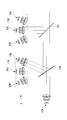
本実施形態に係る照明装置2は、図8に示すように、7つの光源を有する光源ユニット17と、2つのダイクロイックミラー13a,13b及び、ダイクロイックミラー13a,13bを回転させる回転機構14a,14bを備えている。なお、本実施形態において、ダイクロイックミラー13a,13bはショートパス特性を有するものとして説明する。 Second Embodiment
Hereinafter, the illuminatingdevice 2 which concerns on 2nd Embodiment is demonstrated with reference to drawings.
Theillumination device 2 according to the present embodiment, as shown in FIG. 8, includes a light source unit 17 having seven light sources, two dichroic mirrors 13a and 13b, and rotation mechanisms 14a and 14b for rotating the dichroic mirrors 13a and 13b. Have. In the present embodiment, the dichroic mirrors 13a and 13b are described as having short path characteristics.
以下、第2の実施形態に係る照明装置2について、図面を参照して説明する。
本実施形態に係る照明装置2は、図8に示すように、7つの光源を有する光源ユニット17と、2つのダイクロイックミラー13a,13b及び、ダイクロイックミラー13a,13bを回転させる回転機構14a,14bを備えている。なお、本実施形態において、ダイクロイックミラー13a,13bはショートパス特性を有するものとして説明する。 Second Embodiment
Hereinafter, the illuminating
The
光源ユニット17は、ダイクロイックミラー13a,13bを透過する光を射出する光源10Aと、ダイクロイックミラー13a,13bにより反射される光を射出する光源群17A(光源10B,10C,10D)及び光源群17B(10E,10F,10G)を備えている。
The light source unit 17 includes a light source 10A that emits light transmitted through the dichroic mirrors 13a and 13b, a light source group 17A ( light sources 10B, 10C, and 10D) that emits light reflected by the dichroic mirrors 13a and 13b, and a light source group 17B ( light sources 10E, 10F, 10G).
光源群17Aを構成する光源10B,10C,10Dは、同一の円周上に位置する円環状に配置されており、この円環の中心で各光源からの光の光路が交差するように配置されている。同様に、光源群17Bを構成する光源10E,10F,10Gも同一の円周上に位置する円環状に配置されており、この円環の中心で各光源からの光の光路が交差するように配置されている。
そして、光源10A、光源群17A及び光源群17Bは、光源群17Aの各光路の交差位置及び光源群17Bの各光路の交差位置が、光源10Aからの光の光路上に位置するように配置されている。 The light sources 10B, 10C, and 10D constituting the light source group 17A are arranged in the same annular shape in the same circle, and are arranged such that the optical paths of the light from the respective light sources intersect at the center of this ring. ing. Similarly, the light sources 10E, 10F, and 10G constituting the light source group 17B are also arranged in an annular shape located on the same circumference, so that the optical paths of light from the respective light sources intersect at the center of this annular ring. It is arranged.
Thelight source 10A, the light source group 17A and the light source group 17B are arranged such that the intersection position of each light path of the light source group 17A and the intersection position of each light path of the light source group 17B are located on the optical path of light from the light source 10A. ing.
そして、光源10A、光源群17A及び光源群17Bは、光源群17Aの各光路の交差位置及び光源群17Bの各光路の交差位置が、光源10Aからの光の光路上に位置するように配置されている。 The
The
具体的には、図8中、光源群17Aのうち、光源10Bは波長450nmの光を射出し、光源10Aを基準として光源10Aの光路方向に67.5°傾斜して配置する。光源10Cは500nmの光を射出し、光源10Aから光路方向に90°傾斜して配置する。また、光源10Dは、波長550nmの光を射出し、光源10Cから光源10Aの光路方向に22.5°傾斜して配置する。
同様に、光源群17Bのうち、光源10Eは、波長600nmの光を射出し、光源10Aを基準として光源10Aの光路方向に67.5°傾斜して配置する。光源10Fは、波長650nmの光を射出し、光源10Aから光路方向に90°傾斜して配置する。また、光源10Gは、波長700nmの光を射出し、光源10Cから光源10Aの光路方向に22.5°傾斜して配置する。 Specifically, in FIG. 8, in thelight source group 17A, the light source 10B emits light with a wavelength of 450 nm, and is disposed at an inclination of 67.5 ° in the optical path direction of the light source 10A with reference to the light source 10A. The light source 10C emits light of 500 nm and is disposed at an inclination of 90 ° in the optical path direction from the light source 10A. The light source 10D emits light having a wavelength of 550 nm, and is disposed so as to be inclined at 22.5 ° in the optical path direction of the light source 10A from the light source 10C.
Similarly, in thelight source group 17B, the light source 10E emits light with a wavelength of 600 nm, and is disposed at an inclination of 67.5 ° in the optical path direction of the light source 10A with reference to the light source 10A. The light source 10F emits light having a wavelength of 650 nm, and is arranged to be inclined by 90 ° in the optical path direction from the light source 10A. The light source 10G emits light having a wavelength of 700 nm, and is disposed so as to be inclined at 22.5 ° in the optical path direction of the light source 10A from the light source 10C.
同様に、光源群17Bのうち、光源10Eは、波長600nmの光を射出し、光源10Aを基準として光源10Aの光路方向に67.5°傾斜して配置する。光源10Fは、波長650nmの光を射出し、光源10Aから光路方向に90°傾斜して配置する。また、光源10Gは、波長700nmの光を射出し、光源10Cから光源10Aの光路方向に22.5°傾斜して配置する。 Specifically, in FIG. 8, in the
Similarly, in the
光源群17Aの各光路の交差位置にダイクロイックミラー13aが、光源群17Bの各光路の交差位置にダイクロイックミラー13bが配置される。
The dichroic mirror 13a is disposed at the intersection position of each light path of the light source group 17A, and the dichroic mirror 13b is disposed at the intersection position of each light path of the light source group 17B.
以下、このように構成された照明装置2において、光源10Aからの光と、光源10B,10C,10D,10E,10F,10Gからの光を選択して合成光を生成して照射する場合の例について図9~図16を参照して説明する。
Hereinafter, in the illumination device 2 configured as described above, an example in which the light from the light source 10A and the lights from the light sources 10B, 10C, 10D, 10E, 10F, and 10G are selected to generate and emit combined light Will be described with reference to FIGS.
図9に、光源10Aからの光と光源10B及び光源10Fからの光の合成光を生成する場合の例を示した。ダイクロイックミラー13aは45°傾斜の状態から反時計周りに11.25°回転した状態である。ダイクロイックミラー13bは45°傾斜の状態である。ダイクロイックミラー13a,13bの光学特性は、図15(A)及び図16(A)となる。
従って、光源10Aは、ダイクロイックミラー13aを透過した後にダイクロイックミラー13bを透過し、光源10Bは、ダイクロイックミラー13aを反射した後にダイクロイックミラー13bを透過する。そして、光源10Fは、ダイクロイックミラー13bを反射して、合成光が生成される。 FIG. 9 shows an example in the case of generating combined light of the light from thelight source 10A and the light from the light source 10B and the light source 10F. The dichroic mirror 13a is rotated 11.25 ° counterclockwise from the 45 ° inclined state. The dichroic mirror 13 b is in a state of 45 ° inclination. The optical characteristics of the dichroic mirrors 13a and 13b are as shown in FIGS. 15 (A) and 16 (A).
Accordingly, thelight source 10A transmits the dichroic mirror 13a and then transmits the dichroic mirror 13b, and the light source 10B reflects the dichroic mirror 13a and then transmits the dichroic mirror 13b. Then, the light source 10F reflects the dichroic mirror 13b to generate combined light.
従って、光源10Aは、ダイクロイックミラー13aを透過した後にダイクロイックミラー13bを透過し、光源10Bは、ダイクロイックミラー13aを反射した後にダイクロイックミラー13bを透過する。そして、光源10Fは、ダイクロイックミラー13bを反射して、合成光が生成される。 FIG. 9 shows an example in the case of generating combined light of the light from the
Accordingly, the
図10に、光源10Aからの光と光源10C及び光源10Fからの光の合成光を生成する場合の例を示した。ダイクロイックミラー13a,13bは共に45°傾斜の状態である。ダイクロイックミラー13a,13bの光学特性は、図15(B)及び図16(B)となる。
従って、光源10Aは、ダイクロイックミラー13aを透過した後にダイクロイックミラー13bを透過し、光源10Cは、ダイクロイックミラー13aを反射した後にダイクロイックミラー13bを透過する。そして、光源10Fは、ダイクロイックミラー13bを反射して、合成光が生成される。 FIG. 10 shows an example of generating combined light of the light from thelight source 10A and the light from the light source 10C and the light source 10F. The dichroic mirrors 13a and 13b are both inclined at 45 °. The optical characteristics of the dichroic mirrors 13a and 13b are as shown in FIG. 15 (B) and FIG. 16 (B).
Therefore, thelight source 10A transmits the dichroic mirror 13a and then transmits the dichroic mirror 13b, and the light source 10C reflects the dichroic mirror 13a and then transmits the dichroic mirror 13b. Then, the light source 10F reflects the dichroic mirror 13b to generate combined light.
従って、光源10Aは、ダイクロイックミラー13aを透過した後にダイクロイックミラー13bを透過し、光源10Cは、ダイクロイックミラー13aを反射した後にダイクロイックミラー13bを透過する。そして、光源10Fは、ダイクロイックミラー13bを反射して、合成光が生成される。 FIG. 10 shows an example of generating combined light of the light from the
Therefore, the
図11に、光源10Aからの光と光源10D及び光源10Fからの光の合成光を生成する場合の例を示した。ダイクロイックミラー13aは45°傾斜の状態から時計周りに11.25°回転した状態である。ダイクロイックミラー13bは45°傾斜の状態である。ダイクロイックミラー13a,13bの光学特性は、図15(C)及び図16(C)となる。
従って、光源10Aは、ダイクロイックミラー13aを透過した後にダイクロイックミラー13bを透過し、光源10Dは、ダイクロイックミラー13aを反射した後にダイクロイックミラー13bを透過する。そして、光源10Fは、ダイクロイックミラー13bを反射して、合成光が生成される。 FIG. 11 shows an example in the case of generating combined light of the light from thelight source 10A and the light from the light source 10D and the light source 10F. The dichroic mirror 13a is rotated 11.25 ° clockwise from the 45 ° inclined state. The dichroic mirror 13 b is in a state of 45 ° inclination. The optical characteristics of the dichroic mirrors 13a and 13b are as shown in FIG. 15 (C) and FIG. 16 (C).
Therefore, thelight source 10A transmits the dichroic mirror 13a and then the dichroic mirror 13b, and the light source 10D reflects the dichroic mirror 13a and then transmits the dichroic mirror 13b. Then, the light source 10F reflects the dichroic mirror 13b to generate combined light.
従って、光源10Aは、ダイクロイックミラー13aを透過した後にダイクロイックミラー13bを透過し、光源10Dは、ダイクロイックミラー13aを反射した後にダイクロイックミラー13bを透過する。そして、光源10Fは、ダイクロイックミラー13bを反射して、合成光が生成される。 FIG. 11 shows an example in the case of generating combined light of the light from the
Therefore, the
図12に、光源10Aからの光と光源10C及び光源10Eからの光の合成光を生成する場合の例を示した。ダイクロイックミラー13aは45°傾斜の状態である。ダイクロイックミラー13bは45°傾斜の状態から時計周りに11.25°回転した状態である。ダイクロイックミラー13a,13bの光学特性は、図15(D)及び図16(D)となる。
従って、光源10Aは、ダイクロイックミラー13aを透過した後にダイクロイックミラー13bを透過し、光源10Dは、ダイクロイックミラー13aを反射した後にダイクロイックミラー13bを透過する。そして、光源10Eは、ダイクロイックミラー13bを反射して、合成光が生成される。 FIG. 12 shows an example of generating combined light of the light from thelight source 10A and the light from the light source 10C and the light source 10E. The dichroic mirror 13a is in a 45 ° inclined state. The dichroic mirror 13 b is rotated 11.25 ° clockwise from the 45 ° inclined state. The optical characteristics of the dichroic mirrors 13a and 13b are as shown in FIG. 15 (D) and FIG. 16 (D).
Therefore, thelight source 10A transmits the dichroic mirror 13a and then the dichroic mirror 13b, and the light source 10D reflects the dichroic mirror 13a and then transmits the dichroic mirror 13b. Then, the light source 10E reflects the dichroic mirror 13b to generate combined light.
従って、光源10Aは、ダイクロイックミラー13aを透過した後にダイクロイックミラー13bを透過し、光源10Dは、ダイクロイックミラー13aを反射した後にダイクロイックミラー13bを透過する。そして、光源10Eは、ダイクロイックミラー13bを反射して、合成光が生成される。 FIG. 12 shows an example of generating combined light of the light from the
Therefore, the
図13に、光源10Aからの光と光源10C及び光源10Fからの光の合成光を生成する場合の例を示した。ダイクロイックミラー13a,13b共には45°傾斜の状態である。ダイクロイックミラー13a,13bの光学特性は、図15(E)及び図16(E)となる。
従って、光源10Aは、ダイクロイックミラー13aを透過した後にダイクロイックミラー13bを透過し、光源10Fは、ダイクロイックミラー13aを反射した後にダイクロイックミラー13bを透過する。そして、光源10Eは、ダイクロイックミラー13bを反射して、合成光が生成される。 FIG. 13 shows an example in the case of generating combined light of the light from thelight source 10A and the light from the light source 10C and the light from the light source 10F. Both of the dichroic mirrors 13a and 13b are inclined 45 °. The optical characteristics of the dichroic mirrors 13a and 13b are as shown in FIG. 15 (E) and FIG. 16 (E).
Accordingly, thelight source 10A transmits the dichroic mirror 13a and then transmits the dichroic mirror 13b, and the light source 10F reflects the dichroic mirror 13a and then transmits the dichroic mirror 13b. Then, the light source 10E reflects the dichroic mirror 13b to generate combined light.
従って、光源10Aは、ダイクロイックミラー13aを透過した後にダイクロイックミラー13bを透過し、光源10Fは、ダイクロイックミラー13aを反射した後にダイクロイックミラー13bを透過する。そして、光源10Eは、ダイクロイックミラー13bを反射して、合成光が生成される。 FIG. 13 shows an example in the case of generating combined light of the light from the
Accordingly, the
図14に、光源10Aからの光と光源10C及び光源10Gからの光の合成光を生成する場合の例を示した。ダイクロイックミラー13aは45°傾斜の状態である。ダイクロイックミラー13bは45°傾斜の状態から時計周りに11.25°回転した状態である。ダイクロイックミラー13a,13bの光学特性は、図15(F)及び図16(F)となる。
従って、光源10Aは、ダイクロイックミラー13aを透過した後にダイクロイックミラー13bを透過し、光源10Cは、ダイクロイックミラー13aを反射した後にダイクロイックミラー13bを透過する。そして、光源10Gは、ダイクロイックミラー13bを反射して、合成光が生成される。 FIG. 14 shows an example of generating combined light of the light from thelight source 10A and the light from the light source 10C and the light from the light source 10G. The dichroic mirror 13a is in a 45 ° inclined state. The dichroic mirror 13 b is rotated 11.25 ° clockwise from the 45 ° inclined state. The optical characteristics of the dichroic mirrors 13a and 13b are as shown in FIG. 15 (F) and FIG. 16 (F).
Therefore, thelight source 10A transmits the dichroic mirror 13a and then transmits the dichroic mirror 13b, and the light source 10C reflects the dichroic mirror 13a and then transmits the dichroic mirror 13b. Then, the light source 10G reflects the dichroic mirror 13b to generate combined light.
従って、光源10Aは、ダイクロイックミラー13aを透過した後にダイクロイックミラー13bを透過し、光源10Cは、ダイクロイックミラー13aを反射した後にダイクロイックミラー13bを透過する。そして、光源10Gは、ダイクロイックミラー13bを反射して、合成光が生成される。 FIG. 14 shows an example of generating combined light of the light from the
Therefore, the
(第2の実施形態の変形例)
以下、第2の実施形態の変形例に係る照明装置3について、図面を参照して説明する。
本変形例に係る照明装置3は、図17に示すように、4つの光源群を含む光源ユニットと、4つのダイクロイックミラー13a,13b,13c,13d及び、これらのダイクロイックミラー13a,13b,13c,13dを回転させる回転機構14a,14bを備えている。なお、本実施形態において、ダイクロイックミラー13a,13b,13c,13dはショートパス特性を有するものとして説明する。 (Modification of the second embodiment)
Hereinafter, alighting device 3 according to a modification of the second embodiment will be described with reference to the drawings.
Theillumination device 3 according to the present modification, as shown in FIG. 17, includes a light source unit including four light source groups, four dichroic mirrors 13a, 13b, 13c, 13d, and these dichroic mirrors 13a, 13b, 13c, It has rotation mechanisms 14a and 14b for rotating 13d. In the present embodiment, the dichroic mirrors 13a, 13b, 13c, and 13d are described as having short path characteristics.
以下、第2の実施形態の変形例に係る照明装置3について、図面を参照して説明する。
本変形例に係る照明装置3は、図17に示すように、4つの光源群を含む光源ユニットと、4つのダイクロイックミラー13a,13b,13c,13d及び、これらのダイクロイックミラー13a,13b,13c,13dを回転させる回転機構14a,14bを備えている。なお、本実施形態において、ダイクロイックミラー13a,13b,13c,13dはショートパス特性を有するものとして説明する。 (Modification of the second embodiment)
Hereinafter, a
The
照明装置3の光源ユニットは、光源10A及び光源群17A,17B,17C,17Dを備えており、光源群17A,17B,17C,17Dを構成する各光源は夫々円環状に配置され、この円環の中心が光源群17A,17B,17C,17Dを構成する各光源からの光の交差位置となっている。そして、光源群17A,17B,17C,17Dを構成する各光源からの各光路の交差位置が、光源10Aからの光の光路上に位置するように光源10A及び光源群17A,17B,17C,17Dが配置されている。さらに、各交差位置にダイクロイックミラー13a,13b,13c,13dが位置するようになっている。
The light source unit of the illumination device 3 includes the light source 10A and the light source groups 17A, 17B, 17C, and 17D, and the light sources constituting the light source groups 17A, 17B, 17C, and 17D are respectively disposed in an annular shape. The center of the light source group 17A, 17B, 17C, 17D is the cross point of the light from each light source. The light source 10A and the light source groups 17A, 17B, 17C, 17D are positioned such that the intersection position of each light path from the light sources constituting the light source groups 17A, 17B, 17C, 17D is located on the light path of light from the light source 10A. Is arranged. Further, the dichroic mirrors 13a, 13b, 13c and 13d are positioned at the respective intersection positions.
より具体的には、図17中、左端に波長400nmの光を出射する光源10Aを配置する。光源群17Aは、ダイクロイックミラー13aの位置を中心とした円環状に、配置された光源10B,10C,10Dを有し、光源10Bは、図17中、光源10Aを基準に光源10Aの光路方向に時計回りに67.5°傾斜して配置されている。光源10Cは、光源10Bから光源10Aの光路方向に時計回りに22.5°傾斜して、光源10Dは、光源10Cから光源10Aの光路方向に時計回りに22.5°傾斜して夫々配置されている。なお、光源10Bは波長430nmの光を、光源10Cは波長460nmの光を、光源10Dは、波長490nmの光を夫々出射する。
More specifically, in FIG. 17, the light source 10A that emits light with a wavelength of 400 nm is disposed at the left end. The light source group 17A has the light sources 10B, 10C, and 10D disposed in an annular shape centered on the position of the dichroic mirror 13a, and the light source 10B is in the light path direction of the light source 10A with reference to the light source 10A in FIG. It is placed at an inclination of 67.5 ° clockwise. The light source 10C is inclined by 22.5 ° clockwise in the light path direction of the light source 10A from the light source 10B, and the light source 10D is arranged by 22.5 ° clockwise in the light path direction of the light source 10A from the light source 10C. ing. The light source 10B emits light with a wavelength of 430 nm, the light source 10C emits light with a wavelength of 460 nm, and the light source 10D emits light with a wavelength of 490 nm.
続いて、光源群17Bは、ダイクロイックミラー13bの位置を中心とした円環状に、配置された光源10E,10F,10Gを有し、光源10Eは、図17中、光源10Aを基準に光源10Aの光路方向に反時計回りに67.5°傾斜して配置されている。光源10Fは、光源10Eから光源10Aの光路方向に反時計回りに22.5°傾斜して、光源10Gは、光源10Fから光源10Aの光路方向に反時計回りに22.5°傾斜して夫々配置されている。なお、光源10Eは波長520nmの光を、光源10Fは波長550nmの光を、光源10Gは、波長580nmの光を夫々出射する。
Subsequently, the light source group 17B has the light sources 10E, 10F, and 10G disposed in an annular shape centered on the position of the dichroic mirror 13b, and the light source 10E is the light source 10A of FIG. It is disposed at an inclination of 67.5 ° counterclockwise in the light path direction. The light source 10F is inclined 22.5 ° counterclockwise from the light source 10E toward the light path of the light source 10A, and the light source 10G is inclined 22.5 ° counterclockwise from the light source 10F toward the light path from the light source 10A. It is arranged. The light source 10E emits light of wavelength 520 nm, the light source 10F emits light of wavelength 550 nm, and the light source 10G emits light of wavelength 580 nm.
光源群17Cは、ダイクロイックミラー13cの位置を中心とした円環状に、配置された光源10H,10I,10Jを有し、光源10Hは、図17中、光源10Aを基準に光源10Aの光路方向に時計回りに67.5°傾斜して配置されている。光源10Iは、光源10Hから光源10Aの光路方向に時計回りに22.5°傾斜して、光源10Jは、光源10Hから光源10Aの光路方向に時計回りに22.5°傾斜して夫々配置されている。なお、光源10Hは波長610nmの光を、光源10Iは波長640nmの光を、光源10Jは、波長670nmの光を夫々出射する。
The light source group 17C has the light sources 10H, 10I and 10J arranged in a ring shape centering on the position of the dichroic mirror 13c, and the light source 10H is in the light path direction of the light source 10A with reference to the light source 10A in FIG. It is placed at an inclination of 67.5 ° clockwise. The light source 10I is inclined by 22.5 ° clockwise in the light path direction of the light source 10A from the light source 10H, and the light source 10J is disposed by 22.5 ° clockwise in the light path direction of the light source 10A from the light source 10H. ing. The light source 10H emits light having a wavelength of 610 nm, the light source 10I emits light having a wavelength of 640 nm, and the light source 10J emits light having a wavelength of 670 nm.
光源群17Dは、ダイクロイックミラー13dの位置を中心とした円環状に、配置された光源10K,10L,10Mを有し、光源10Kは、図17中、光源10Aを基準に光源10Aの光路方向に反時計回りに67.5°傾斜して配置されている。光源10Lは、光源10Kから光源10Aの光路方向に反時計回りに22.5°傾斜して、光源10Mは、光源10Lから光源10Aの光路方向に反時計回りに22.5°傾斜して夫々配置されている。なお、光源10Kは波長700nmの光を、光源10Lは波長730nmの光を、光源10Mは、波長760nmの光を夫々出射する。
The light source group 17D has the light sources 10K, 10L and 10M arranged in an annular shape centering on the position of the dichroic mirror 13d, and the light source 10K is in the light path direction of the light source 10A with reference to the light source 10A in FIG. It is placed counterclockwise at 67.5 °. The light source 10L is inclined 22.5 ° counterclockwise from the light source 10K toward the light path of the light source 10A, and the light source 10M is inclined 22.5 ° counterclockwise from the light source 10L toward the light path from the light source 10L. It is arranged. The light source 10K emits light having a wavelength of 700 nm, the light source 10L emits light having a wavelength of 730 nm, and the light source 10M emits light having a wavelength of 760 nm.
(第3の実施形態)
以下、第3の実施形態に係る照明装置4について、図面を参照して説明する。
本実施形態に係る照明装置4は、上述した各実施形態のように光源が円環状に配置されておらず、光源10B,10C,10Dが直線上に配置されている。 Third Embodiment
Theillumination device 4 according to the third embodiment will be described below with reference to the drawings.
In theillumination device 4 according to the present embodiment, the light sources are not arranged in an annular shape as in the above-described embodiments, and the light sources 10B, 10C, and 10D are linearly arranged.
以下、第3の実施形態に係る照明装置4について、図面を参照して説明する。
本実施形態に係る照明装置4は、上述した各実施形態のように光源が円環状に配置されておらず、光源10B,10C,10Dが直線上に配置されている。 Third Embodiment
The
In the
具体的には、図18中、ショートパス特性を有するダイクロイックミラー13を透過する400nmの光を出射する光源10Aが左端に配置され、光源10Aの光路に直交する位置に光源10B,10C,10Dが等間隔に配置されている。光源10B,光源10Dは光路変更部材としてのプリズム16b,16dを有しており、光源10Bからの光はプリズム16bにより、光源10Dからの光はプリズム16dにより、光源10Cからの光の光路と同じ位置で交差するようになっている。そして、この交差位置が光源10Aからの光の光路上となるようになっている。
なお、光源10Bは波長450nmの光を、光源10Cは波長500nmの光を、光源10Dは波長550nmの光を夫々出射する。 Specifically, in FIG. 18, thelight source 10A emitting the light of 400 nm transmitting the dichroic mirror 13 having short path characteristics is disposed at the left end, and the light sources 10B, 10C, and 10D are disposed at positions orthogonal to the light path of the light source 10A. It is arranged at equal intervals. The light source 10B and the light source 10D have the prisms 16b and 16d as optical path changing members, the light from the light source 10B is the same as the light path of the light from the light source 10C by the prism 16b and the light from the light source 10D by the prism 16d. It is supposed to cross at the position. Then, the intersection position is on the light path of the light from the light source 10A.
Thelight source 10B emits light with a wavelength of 450 nm, the light source 10C emits light with a wavelength of 500 nm, and the light source 10D emits light with a wavelength of 550 nm.
なお、光源10Bは波長450nmの光を、光源10Cは波長500nmの光を、光源10Dは波長550nmの光を夫々出射する。 Specifically, in FIG. 18, the
The
以下、このように構成された照明装置4において、例えば光源10Aからの光と、光源10B,10C,10Dからの光を選択して合成光を生成して照射する場合について図19を参照して説明する。なお、ここでは、プリズム16b,16dにより光源10B及び光源10Dからの光が光源10Cからの光に対して22.5°傾斜してダイクロイックミラー13に入射するようになっていることとする。
Hereinafter, in the illumination device 4 configured as described above, for example, a case where the light from the light source 10A and the light from the light sources 10B, 10C, and 10D are selected to generate and emit combined light will be described with reference to FIG. explain. Here, it is assumed that the light from the light source 10B and the light source 10D is inclined by 22.5 ° with respect to the light from the light source 10C and enters the dichroic mirror 13 by the prisms 16b and 16d.
図19(A)に、光源10Aからの光と光源10Bからの光の合成光を生成する場合の例を示した。ダイクロイックミラー13は45°傾斜の状態から反時計周りに22.5°回転した状態である。この時のダイクロイックミラーの光学特性は、図15(A)及び図16(A)となる。従って、光源10Aからの光はダイクロイックミラー13を透過し、光源10Bからの光はダイクロイックミラー13を反射して、合成光が生成される。
FIG. 19A shows an example of generating combined light of the light from the light source 10A and the light from the light source 10B. The dichroic mirror 13 is rotated by 22.5 degrees counterclockwise from the 45 ° inclined state. The optical characteristics of the dichroic mirror at this time are as shown in FIG. 15 (A) and FIG. 16 (A). Accordingly, the light from the light source 10A is transmitted through the dichroic mirror 13, and the light from the light source 10B is reflected by the dichroic mirror 13 to generate combined light.
図19(B)に示す例では、光源10Aからの光と光源10Cからの光の合成光を生成する。ダイクロイックミラー13は45°傾斜の状態から反時計周りに11.25°回転した状態である。この時の、ダイクロイックミラー13の光学特性は、図15(B)及び図16(B)となる。従って、光源10Aからの光はダイクロイックミラー13を透過し、光源10Cからの光はダイクロイックミラー13を反射して、合成光が生成される。
In the example shown in FIG. 19B, combined light of the light from the light source 10A and the light from the light source 10C is generated. The dichroic mirror 13 is rotated 11.25 ° counterclockwise from the 45 ° inclined state. The optical characteristics of the dichroic mirror 13 at this time are as shown in FIG. 15 (B) and FIG. 16 (B). Accordingly, the light from the light source 10A is transmitted through the dichroic mirror 13, and the light from the light source 10C is reflected by the dichroic mirror 13 to generate combined light.
図19(C)に示す例では、光源10Aからの光と光源10Dからの光の合成光を生成する。ダイクロイックミラー13は45°傾斜の状態である。ダイクロイックミラー13の光学特性は、図15(C)及び図16(C)となる。従って、光源10Aからの光はダイクロイックミラーを透過し、光源10Dからの光はダイクロイックミラーを反射して、色合成がされて照明する。
In the example shown in FIG. 19C, combined light of the light from the light source 10A and the light from the light source 10D is generated. The dichroic mirror 13 is inclined at 45 °. The optical characteristics of the dichroic mirror 13 are as shown in FIG. 15 (C) and FIG. 16 (C). Accordingly, the light from the light source 10A is transmitted through the dichroic mirror, and the light from the light source 10D is reflected by the dichroic mirror to be color synthesized and illuminated.
(第3の実施形態の変形例)
以下、第3の実施形態の変形例に係る照明装置5について、図面を参照して説明する。
本実施形態は、上述した第3の実施形態と同様に、各光源が直線上に配置されており、直線上に配置された3つの光源からなる光源群を2つ備えた例である。 (Modification of the third embodiment)
Hereinafter, theillumination device 5 according to the modification of the third embodiment will be described with reference to the drawings.
Similar to the third embodiment described above, the present embodiment is an example in which each light source is disposed on a straight line, and two light source groups each including three light sources disposed on the straight line are provided.
以下、第3の実施形態の変形例に係る照明装置5について、図面を参照して説明する。
本実施形態は、上述した第3の実施形態と同様に、各光源が直線上に配置されており、直線上に配置された3つの光源からなる光源群を2つ備えた例である。 (Modification of the third embodiment)
Hereinafter, the
Similar to the third embodiment described above, the present embodiment is an example in which each light source is disposed on a straight line, and two light source groups each including three light sources disposed on the straight line are provided.
具体的には、図20中、ショートパス特性を有するダイクロイックミラー13a,13bを透過する400nmの光を出射する光源10Aが左端に配置され、光源10Aの光路に直交する位置に光源10B,10C,10Dからなる光源群17Aと、光源10E,10F,10Gからなる光源群17Bが等間隔に配置されている。
Specifically, in FIG. 20, the light source 10A for emitting light of 400 nm that transmits the dichroic mirrors 13a and 13b having short path characteristics is disposed at the left end, and is orthogonal to the light path of the light source 10A. A light source group 17A consisting of 10D and a light source group 17B consisting of light sources 10E, 10F, 10G are arranged at equal intervals.
光源10B,光源10D,10E,10Gは光路変更部材としてのプリズム16b,16d,16e,16fを有しており、光源10Bからの光はプリズム16bにより、光源10Dからの光はプリズム16dにより、光源10Cからの光の光路と同じ位置で交差するようになっている。同様に、光源10Eからの光はプリズム16eにより、光源10Gからの光はプリズム16gにより、光源10Cからの光の光路と同じ位置で交差するようになっている。そして、これら各交差位置が光源10Aからの光の光路上となるようになっている。
なお、光源10Bは波長450nmの光を、光源10Cは波長500nmの光を、光源10Dは波長550nmの光を、光源10Dは600nmの光を、光源10E650nmの光を、光源10Gは700nmの光を夫々出射する。 Thelight source 10B and the light sources 10D, 10E and 10G have prisms 16b, 16d, 16e and 16f as light path changing members, the light from the light source 10B is by the prism 16b and the light from the light source 10D is by the prism 16d It intersects at the same position as the optical path of light from 10C. Similarly, the light from the light source 10E is crossed by the prism 16e, and the light from the light source 10G is crossed by the prism 16g at the same position as the light path of the light from the light source 10C. And each intersection position becomes an optical path of the light from light source 10A.
Thelight source 10B has a wavelength of 450 nm, the light source 10C has a wavelength of 500 nm, the light source 10D has a light of 550 nm, the light source 10D has a light of 600 nm, the light source 10E has a wavelength of 650 nm, and the light source 10G has a light of 700 nm. Each one emits radiation.
なお、光源10Bは波長450nmの光を、光源10Cは波長500nmの光を、光源10Dは波長550nmの光を、光源10Dは600nmの光を、光源10E650nmの光を、光源10Gは700nmの光を夫々出射する。 The
The
上述した各実施形態においては、発光素子としてLEDを適用したが、これに限られるものではなく、例えばLD、ランプ等を適用することができる。また、光学素子としてダイクロイックミラーを適用したが、これに限られるものではなく、例えば、ダイクロイックプリズム等を適用することもできる。
In each embodiment mentioned above, although LED was applied as a light emitting element, it is not restricted to this, for example, LD, a lamp, etc. are applicable. Moreover, although the dichroic mirror was applied as an optical element, it is not restricted to this, For example, a dichroic prism etc. can also be applied.
このように、ダイクロイックミラーを回転可能に設けることで種々の光源の配置構成が可能となる。そして、光源10Aからの光は、ダイクロイックミラー13を透過して直進する透過光路を通過する一方、回転機構によりダイクロイックミラー13の回転角を調節すると、他の光源10B,10C,10D等の何れかからの光が、ダイクロイックミラー13により反射されて、光源10Aからの光の透過光路に入射する。回転機構14によってダイクロイックミラー13の回転角を切り替えると、透過光路に入射させる光を射出する光源を切り替えることができる。すなわち、1つのダイクロイックミラー13により3つ以上の光源10A,10B,10C,10D等からの光を一つの光路に入射させることができ、光の透過又は反射の際の光の損失を抑制することができる。従って、異なる複数波長の光を適宜選択し、かつ、導光効率を向上させてより高輝度の光を照射することができる。
Thus, various arrangements of light sources can be made by rotatably providing the dichroic mirror. The light from the light source 10A passes through the transmitted light path that passes straight through the dichroic mirror 13, while adjusting the rotation angle of the dichroic mirror 13 by the rotation mechanism, any of the other light sources 10B, 10C, 10D, etc. The light from the light source 10 is reflected by the dichroic mirror 13 and enters the transmission light path of the light from the light source 10A. When the rotation angle of the dichroic mirror 13 is switched by the rotation mechanism 14, it is possible to switch the light source for emitting the light to be incident on the transmission light path. That is, light from three or more light sources 10A, 10B, 10C, 10D, etc. can be made incident on one optical path by one dichroic mirror 13, and the loss of light when transmitting or reflecting the light is suppressed. Can. Therefore, light of a plurality of different wavelengths can be appropriately selected, and the light guiding efficiency can be improved to emit light of higher luminance.
1,2,3,4,5 照明装置
10A,10B,10C,10D,10E,10F,10G,10H,10I,10J,10K,10L,10M 光源
11 発光素子
12a,12b コリメートレンズ
13a,13b,13c,13d ダイクロイックミラー
14 回転機構
16b,16d,16e,16g プリズム
17A,17B,17C,17D 光源群 1, 2, 3, 4, 5 illumination devices 10A, 10B, 10C, 10D, 10E, 10F, 10G, 10I, 10J, 10K, 10L, 10M light sources 11 light emitting elements 12a, 12b collimate lenses 13a, 13b, 13c , 13d dichroic mirror 14 rotation mechanism 16b, 16d, 16e, 16g prisms 17A, 17B, 17C, 17D light source group
10A,10B,10C,10D,10E,10F,10G,10H,10I,10J,10K,10L,10M 光源
11 発光素子
12a,12b コリメートレンズ
13a,13b,13c,13d ダイクロイックミラー
14 回転機構
16b,16d,16e,16g プリズム
17A,17B,17C,17D 光源群 1, 2, 3, 4, 5
Claims (3)
- 光軸を一点で交差させて配列され夫々異なる波長領域の光を出射する3つ以上の光源と、
該光源のうち一の光源からの光を透過すると共に他の光源からの光を反射して、前記一の光源からの光の光路に入射させる光学素子と、
該光学素子を前記光源の配列方向に回転させる光学素子回転手段と
を備える照明装置。 Three or more light sources arranged so as to cross the optical axis at one point and emitting light in different wavelength regions,
An optical element that transmits light from one of the light sources and reflects light from the other light source to be incident on a light path of light from the one light source;
And an optical element rotating means for rotating the optical element in the arrangement direction of the light sources. - 複数の前記光源が円環状に配置され、該円環状に配置された複数の光源の中心に前記光学素子が配置された請求項1に記載の照明装置。 The lighting device according to claim 1, wherein the plurality of light sources are disposed in an annular shape, and the optical element is disposed at the center of the plurality of light sources disposed in the annular shape.
- 複数の前記光源が等間隔に配置されている請求項1又は請求項2に記載の照明装置。 The lighting device according to claim 1, wherein a plurality of the light sources are arranged at equal intervals.
Priority Applications (3)
| Application Number | Priority Date | Filing Date | Title |
|---|---|---|---|
| CN201280066532.4A CN104040243A (en) | 2012-01-12 | 2012-12-25 | Illuminating apparatus |
| EP12865111.4A EP2803899A4 (en) | 2012-01-12 | 2012-12-25 | Illuminating apparatus |
| US14/323,801 US9915413B2 (en) | 2012-01-12 | 2014-07-03 | Illumination apparatus |
Applications Claiming Priority (2)
| Application Number | Priority Date | Filing Date | Title |
|---|---|---|---|
| JP2012004115A JP2013143329A (en) | 2012-01-12 | 2012-01-12 | Lighting system |
| JP2012-004115 | 2012-01-12 |
Related Child Applications (1)
| Application Number | Title | Priority Date | Filing Date |
|---|---|---|---|
| US14/323,801 Continuation US9915413B2 (en) | 2012-01-12 | 2014-07-03 | Illumination apparatus |
Publications (1)
| Publication Number | Publication Date |
|---|---|
| WO2013105432A1 true WO2013105432A1 (en) | 2013-07-18 |
Family
ID=48781390
Family Applications (1)
| Application Number | Title | Priority Date | Filing Date |
|---|---|---|---|
| PCT/JP2012/083518 WO2013105432A1 (en) | 2012-01-12 | 2012-12-25 | Illuminating apparatus |
Country Status (5)
| Country | Link |
|---|---|
| US (1) | US9915413B2 (en) |
| EP (1) | EP2803899A4 (en) |
| JP (1) | JP2013143329A (en) |
| CN (1) | CN104040243A (en) |
| WO (1) | WO2013105432A1 (en) |
Cited By (1)
| Publication number | Priority date | Publication date | Assignee | Title |
|---|---|---|---|---|
| CN106574755A (en) * | 2014-08-22 | 2017-04-19 | 奥林巴斯株式会社 | Light source device |
Families Citing this family (4)
| Publication number | Priority date | Publication date | Assignee | Title |
|---|---|---|---|---|
| CN106950687B (en) * | 2016-01-06 | 2021-01-01 | 松下知识产权经营株式会社 | Image generation system and image generation method |
| CN112513718B (en) | 2018-06-22 | 2023-07-14 | 奇跃公司 | Method and system for RGB luminaire |
| JP2022057427A (en) * | 2020-09-30 | 2022-04-11 | レボックス株式会社 | Light source device |
| DE102021100572A1 (en) | 2021-01-13 | 2022-07-14 | Happersberger Otopront Gmbh | Lighting device for an endoscopy system and endoscopy system with a lighting device |
Citations (3)
| Publication number | Priority date | Publication date | Assignee | Title |
|---|---|---|---|---|
| JPH0566366A (en) * | 1991-09-10 | 1993-03-19 | Hitachi Ltd | Liquid crystal projection device |
| JP2001042431A (en) | 1999-07-30 | 2001-02-16 | Nitto Kogaku Kk | Light source device and projector device |
| JP2004138866A (en) * | 2002-10-18 | 2004-05-13 | Sony Corp | Optical device |
Family Cites Families (12)
| Publication number | Priority date | Publication date | Assignee | Title |
|---|---|---|---|---|
| JP3914819B2 (en) * | 2002-05-24 | 2007-05-16 | オリンパス株式会社 | Illumination device and image projection device |
| JP2004335992A (en) * | 2003-04-18 | 2004-11-25 | Victor Co Of Japan Ltd | Light source unit and projection display device applied with the light source unit |
| US7101050B2 (en) * | 2004-05-14 | 2006-09-05 | 3M Innovative Properties Company | Illumination system with non-radially symmetrical aperture |
| JP2006023436A (en) * | 2004-07-07 | 2006-01-26 | Olympus Corp | Illuminating apparatus and projector |
| DE102005027312A1 (en) * | 2005-06-13 | 2006-12-14 | Sensovation Ag | microscope |
| JP2007157548A (en) * | 2005-12-06 | 2007-06-21 | Fujinon Corp | Light source device and projector |
| EP1918757A1 (en) * | 2006-11-02 | 2008-05-07 | Olympus Corporation | Microscope illumination apparatus |
| CN102089701B (en) * | 2008-05-15 | 2012-12-26 | 3M创新有限公司 | Optical element and color combiner |
| CN102472897B (en) * | 2009-07-13 | 2014-10-22 | 马丁专业公司 | Color-combining illumination device |
| JP2011243440A (en) * | 2010-05-19 | 2011-12-01 | Olympus Corp | Illumination device |
| CN201706387U (en) * | 2010-06-19 | 2011-01-12 | 麦克奥迪实业集团有限公司 | Illumination device capable of rapidly switching different wavelengths |
| JP5966363B2 (en) * | 2011-06-20 | 2016-08-10 | 株式会社リコー | Light source device and image projection device |
-
2012
- 2012-01-12 JP JP2012004115A patent/JP2013143329A/en active Pending
- 2012-12-25 EP EP12865111.4A patent/EP2803899A4/en not_active Withdrawn
- 2012-12-25 CN CN201280066532.4A patent/CN104040243A/en active Pending
- 2012-12-25 WO PCT/JP2012/083518 patent/WO2013105432A1/en active Application Filing
-
2014
- 2014-07-03 US US14/323,801 patent/US9915413B2/en active Active
Patent Citations (3)
| Publication number | Priority date | Publication date | Assignee | Title |
|---|---|---|---|---|
| JPH0566366A (en) * | 1991-09-10 | 1993-03-19 | Hitachi Ltd | Liquid crystal projection device |
| JP2001042431A (en) | 1999-07-30 | 2001-02-16 | Nitto Kogaku Kk | Light source device and projector device |
| JP2004138866A (en) * | 2002-10-18 | 2004-05-13 | Sony Corp | Optical device |
Non-Patent Citations (1)
| Title |
|---|
| See also references of EP2803899A4 |
Cited By (1)
| Publication number | Priority date | Publication date | Assignee | Title |
|---|---|---|---|---|
| CN106574755A (en) * | 2014-08-22 | 2017-04-19 | 奥林巴斯株式会社 | Light source device |
Also Published As
| Publication number | Publication date |
|---|---|
| US20140321114A1 (en) | 2014-10-30 |
| JP2013143329A (en) | 2013-07-22 |
| EP2803899A1 (en) | 2014-11-19 |
| CN104040243A (en) | 2014-09-10 |
| US9915413B2 (en) | 2018-03-13 |
| EP2803899A4 (en) | 2015-07-08 |
Similar Documents
| Publication | Publication Date | Title |
|---|---|---|
| JP6171345B2 (en) | Illumination light source device, projection device equipped with this illumination light source device, and control method of projection device | |
| WO2013105432A1 (en) | Illuminating apparatus | |
| JP6056293B2 (en) | Illumination light source device, projection device equipped with this illumination light source device, and control method of projection device | |
| JP2020202182A (en) | Luminaire and projection device | |
| JP6102132B2 (en) | Illumination light source device, projection device equipped with this illumination light source device, and control method of projection device | |
| WO2011092841A1 (en) | Illumination optical system and projector using same | |
| JP6164674B2 (en) | Lamp and method for using such a lamp | |
| JP2013076968A (en) | Illuminator, projector and method for controlling projector | |
| JP2011243440A (en) | Illumination device | |
| TW201235620A (en) | Colour-tunable light source unit with phosphor element | |
| JP2014199412A (en) | Illumination light source device and projection device including the same | |
| JP6255680B2 (en) | Illumination light source device and projection device using the same | |
| JP5598968B2 (en) | Light source configuration for illumination device of medical optical observation apparatus | |
| WO2017051868A1 (en) | Lighting device | |
| JP5394805B2 (en) | Ring lighting device | |
| US9737204B2 (en) | Retinal imaging apparatus and method | |
| US9903543B2 (en) | Lighting device providing light mixed from several light sources | |
| RU2010154659A (en) | LIGHT-RADIATING DEVICE AND METHOD FOR RADIATING LIGHT | |
| JP4579554B2 (en) | Microscope illumination system | |
| US11835202B2 (en) | Illumination device | |
| JP2017117725A (en) | Vehicular headlight device | |
| JP6979168B2 (en) | Lighting equipment | |
| WO2023042274A1 (en) | Light source device and endoscope system equipped with same | |
| WO2012111435A1 (en) | Illumination device | |
| JP6048051B2 (en) | Illumination device, microscope system, microscope, and control method |
Legal Events
| Date | Code | Title | Description |
|---|---|---|---|
| 121 | Ep: the epo has been informed by wipo that ep was designated in this application |
Ref document number: 12865111 Country of ref document: EP Kind code of ref document: A1 |
|
| WWE | Wipo information: entry into national phase |
Ref document number: 2012865111 Country of ref document: EP |
|
| NENP | Non-entry into the national phase |
Ref country code: DE |