WO2013100638A1 - Appareil et procédé pour préparer une bande de nanofibres - Google Patents
Appareil et procédé pour préparer une bande de nanofibres Download PDFInfo
- Publication number
- WO2013100638A1 WO2013100638A1 PCT/KR2012/011589 KR2012011589W WO2013100638A1 WO 2013100638 A1 WO2013100638 A1 WO 2013100638A1 KR 2012011589 W KR2012011589 W KR 2012011589W WO 2013100638 A1 WO2013100638 A1 WO 2013100638A1
- Authority
- WO
- WIPO (PCT)
- Prior art keywords
- nanofiber web
- spinning nozzle
- nanofibers
- polymer melt
- manufacturing apparatus
- Prior art date
Links
Images


Classifications
-
- D—TEXTILES; PAPER
- D01—NATURAL OR MAN-MADE THREADS OR FIBRES; SPINNING
- D01D—MECHANICAL METHODS OR APPARATUS IN THE MANUFACTURE OF ARTIFICIAL FILAMENTS, THREADS, FIBRES, BRISTLES OR RIBBONS
- D01D5/00—Formation of filaments, threads, or the like
- D01D5/0007—Electro-spinning
- D01D5/0061—Electro-spinning characterised by the electro-spinning apparatus
- D01D5/0069—Electro-spinning characterised by the electro-spinning apparatus characterised by the spinning section, e.g. capillary tube, protrusion or pin
-
- D—TEXTILES; PAPER
- D01—NATURAL OR MAN-MADE THREADS OR FIBRES; SPINNING
- D01D—MECHANICAL METHODS OR APPARATUS IN THE MANUFACTURE OF ARTIFICIAL FILAMENTS, THREADS, FIBRES, BRISTLES OR RIBBONS
- D01D5/00—Formation of filaments, threads, or the like
- D01D5/0007—Electro-spinning
- D01D5/0015—Electro-spinning characterised by the initial state of the material
- D01D5/0023—Electro-spinning characterised by the initial state of the material the material being a polymer melt
-
- D—TEXTILES; PAPER
- D04—BRAIDING; LACE-MAKING; KNITTING; TRIMMINGS; NON-WOVEN FABRICS
- D04H—MAKING TEXTILE FABRICS, e.g. FROM FIBRES OR FILAMENTARY MATERIAL; FABRICS MADE BY SUCH PROCESSES OR APPARATUS, e.g. FELTS, NON-WOVEN FABRICS; COTTON-WOOL; WADDING ; NON-WOVEN FABRICS FROM STAPLE FIBRES, FILAMENTS OR YARNS, BONDED WITH AT LEAST ONE WEB-LIKE MATERIAL DURING THEIR CONSOLIDATION
- D04H1/00—Non-woven fabrics formed wholly or mainly of staple fibres or like relatively short fibres
- D04H1/70—Non-woven fabrics formed wholly or mainly of staple fibres or like relatively short fibres characterised by the method of forming fleeces or layers, e.g. reorientation of fibres
- D04H1/72—Non-woven fabrics formed wholly or mainly of staple fibres or like relatively short fibres characterised by the method of forming fleeces or layers, e.g. reorientation of fibres the fibres being randomly arranged
- D04H1/728—Non-woven fabrics formed wholly or mainly of staple fibres or like relatively short fibres characterised by the method of forming fleeces or layers, e.g. reorientation of fibres the fibres being randomly arranged by electro-spinning
-
- D—TEXTILES; PAPER
- D01—NATURAL OR MAN-MADE THREADS OR FIBRES; SPINNING
- D01D—MECHANICAL METHODS OR APPARATUS IN THE MANUFACTURE OF ARTIFICIAL FILAMENTS, THREADS, FIBRES, BRISTLES OR RIBBONS
- D01D5/00—Formation of filaments, threads, or the like
- D01D5/18—Formation of filaments, threads, or the like by means of rotating spinnerets
Definitions
- the present invention relates to a nanofiber web manufacturing apparatus and method, and more particularly to a nanofiber web manufacturing apparatus and method for producing a nanofiber web by discharging the polymer melt into an electric field to collect and collect the nanofiber.
- an apparatus for manufacturing nanofiber web using electrospinning is a device for manufacturing a nanofiber web by discharging a polymer melt, which is a raw material of nanofiber, into an electric field.
- An example of such a nanofiber web manufacturing apparatus is Korean Patent No. 10-0549140. It is disclosed in the preceding document.
- the apparatus for manufacturing nanofiber webs disclosed in the related art is heat-melted by a thermoplastic polymer with a melt extruder 1 to extrude a spinning melt, and the spinning melt extruded from the melt extruder 1 is at the tip of the spinning nozzle part 4. It discharges to the electrospinning region to which a high voltage was applied through the nozzle 5, and the discharged molten melt is radiated to the ultrafine fiber by the electric force of the electric field of the electrospinning region, and is integrated in the integrated board 10 of the lower part.
- the conventional integrated plate 10 is formed in a flat plate shape in order to manufacture a wide nanofiber web should be provided with a plurality of spinning nozzle portions 4 at regular intervals along the width direction to reach a few meters in width.
- the conventional integrated plate 10 is formed in a flat plate shape in order to manufacture a wide nanofiber web should be provided with a plurality of spinning nozzle portions 4 at regular intervals along the width direction to reach a few meters in width.
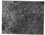
- the nanofibers are tangled irregularly without a certain direction as shown in Figure 1 to form a nanofiber web, comparing the space between the nanofibers per unit area can be seen that the deviation of the space is large. This means that the distribution of nanofibers is not uniform, there is a problem that the quality of the nanofiber web is reduced.
- the passage rate or filtration rate is not constant in the case of using the material to pass or filter the space between the nanofibers.
- the "anisotropic conductive film" disclosed in Patent Registration No. 10-1115686 is characterized in that the conductive particles are fixed to the nanofibers, and the distribution of the conductive particles is changed according to the distribution of the nanofibers, and thus the conductivity per unit area The conductivity varies depending on the number of particles, making it difficult to achieve high quality electrical connection performance required by electronic components.
- the present invention was created to improve the problems of the conventional nanofiber web manufacturing apparatus and method as described above, it is possible to improve the physical properties by increasing the tensile force of the nanofiber web and to make a wide nanofiber web with a small number of nozzles It is an object of the present invention to provide a nanofiber web manufacturing apparatus and method that can be produced.
- the nanofiber web manufacturing apparatus includes a rotating shaft and a discharge passage provided in a circular motion about the rotating shaft and containing a polymer melt, and crossing the rotating shaft.
- a plurality of spinning nozzles for discharging the polymer melt a rotating unit for rotating the rotary shaft, an integrated plate spaced apart from the front end of the spinning nozzle at a predetermined distance, and an electric field in the space between the spinning nozzle and the integrated plate. It characterized in that it comprises a high voltage generator to form.
- the radiation nozzles may be provided radially with a plurality of radial nozzles at predetermined angles along the circumferential direction of the rotation shaft.
- the spinning nozzle may be provided in a plurality of rows with a predetermined interval along the axial direction of the rotation axis.
- the present invention further includes a distribution unit for supplying the polymer melt to the discharge passages of the plurality of spinning nozzles.
- the radiation nozzle is provided so that the distance to the integrated plate in a direction crossing the rotation axis.
- a base paper is provided to collect the nanofibers discharged from the spinning nozzle in an electric field between the spinning nozzle and the integrated plate, and the base paper is provided to be in close contact with the inner wall of the integrated plate along the circumferential direction of the rotating shaft. Can be.
- the integrated member is preferably formed to be bent in an arc shape.
- the base paper may be provided to be movable in close contact with the inner wall of the integrated plate in the axial direction of the rotation axis, wherein the integrated plate may be formed in a cylindrical shape.
- the nanofiber web manufacturing apparatus in order to achieve the above object, as a nanofiber web manufacturing apparatus for producing a nanofiber web by discharging a polymer melt into an electric field to produce and collect the nanofiber web, the rotating shaft And a spinning unit configured to axially rotate the rotary shaft, a spinning nozzle provided in a circular motion about the rotary shaft and receiving a polymer melt and discharging the polymer melt in a direction crossing the rotary shaft;
- a drawing unit which draws the nanofibers discharged from the nozzle into the electric field and is formed along the axial direction of the rotation axis to form a tubular nanofiber web, and presses one side of the nanofiber webs drawn out in the tubular shape by the drawing unit It characterized in that it comprises a folding member to be folded in two layers.
- the drawing unit includes a collecting member for collecting nanofibers discharged from the spinning nozzle while moving along the axial direction of the rotation shaft.
- the collecting member may be provided to be movable in an endless orbital manner.
- the collecting member may be formed linearly, in particular, the collecting member may be composed of any one of a wire, a belt, and a seal.
- a plurality of collecting members may be provided at predetermined intervals along the circumferential direction of the rotating shaft.
- the drawing unit further includes a pulling member for pulling the nanofiber web discharged from the spinning nozzle and collected in an annular shape along the axial direction of the rotation axis to form a tubular nanofiber web.
- the present invention further includes a blowing unit for supplying air into the nanofiber web so that the nanofiber web formed tubularly by the drawing unit is inflated.
- the present invention preferably further includes a guide member for guiding the inner diameter of the nanofiber web formed in the tubular shape by the drawing unit to be closer to the folding member.
- the nanofibers are discharged from the spinning nozzle by circulating the spinning nozzle around the rotation axis in the electric field circumferential direction of the rotation axis of the circular motion
- the polymer melt is discharged from the other spinning nozzle circumferentially about the other axis of rotation forming a predetermined angle between the axis of rotation and the surface of the nanofibers formed in the circumferential direction of the axis of rotation by the circular motion of the spinning nozzle
- the nanofiber web manufacturing method according to the present invention in order to achieve the above object, as a nanofiber web manufacturing method for producing a nanofiber web by discharging the polymer melt into an electric field to produce and collect the nanofiber, Collecting the polymer melt from the spinning nozzle in a circular motion around the axis of rotation within the collecting step of collecting the nanofibers in an annular shape, and in the collecting step to transfer the nanofiber web formed in an annular in the axial direction of the rotation axis of the tubular shape It is characterized in that it comprises a withdrawal step of forming a nanofiber web, and a folding step of superimposing the nanofiber web formed in a tubular shape in the withdrawal step in two layers.
- the present invention further includes a cutting step of manufacturing one layer of the nanofiber web by cutting one side of the nanofiber web stacked in the folding step.
- the blowing step further includes a blowing step of inflating the nanofiber web by injecting air into the nanofiber web formed in a tubular shape.
- a plurality of collecting members for trapping nanofibers formed by electrospinning a polymer melt are provided with a predetermined distance from each other, and the nanofiber web is electrospun on one side of the plurality of collecting members. It is characterized in that the fixed combination.
- the collecting member may be formed linearly, and the collecting member may be formed of any one of a wire, a belt, and a seal.
- the nanofiber web is formed in a tubular shape
- the collecting member is provided with a plurality of spaced intervals along the circumferential direction of the tubular nanofiber web, each collecting member is an axial direction of the nanofiber web Along linearly.
- FIG. 2 is a conceptual diagram showing a nanofiber web manufacturing apparatus according to an embodiment of the present invention
- FIG. 3 is a schematic side cross-sectional view cut along the line A-A of FIG.
- 4 and 5 is a conceptual diagram showing the radiation form through the radiation nozzle shown in FIG.
- FIG. 7 is an enlarged view of the radiation nozzle shown in FIG.
- FIG. 9 is a schematic cross-sectional view showing a spinning nozzle according to another embodiment of the present invention.
- FIG. 10 is a conceptual diagram showing a nanofiber web manufacturing apparatus according to another embodiment of the present invention.
- FIG. 11 is a perspective view showing a shape in which the base paper shown in FIG.
- FIG. 12 is a conceptual diagram showing a nanofiber web manufacturing method according to an embodiment of the present invention.
- Figure 13 is a conceptual diagram showing a nanofiber web manufacturing apparatus according to an embodiment of the present invention.
- FIG. 16 is a conceptual diagram showing a nanofiber web manufacturing apparatus according to another embodiment of the present invention.
- 17 is a schematic cross-sectional view taken along the line C-C of FIG. 16,
- FIG. 19 is a conceptual view showing another embodiment of the withdrawal unit according to the present invention.
- 21 is a conceptual view showing another embodiment of the withdrawal unit according to the present invention.
- FIG. 22 is a schematic perspective view of the nanofiber web manufacturing apparatus shown in FIG.
- the nanofiber web manufacturing apparatus according to an embodiment of the present invention, the rotary shaft 10, a plurality of spinning nozzle 20 is provided so as to be circularly moved around the rotary shaft (10) ), A rotary unit for axially rotating the rotary shaft 10, a distribution unit for supplying a polymer melt to the plurality of spinning nozzles 20, an integration formed in a curved shape at a predetermined distance from a tip of the spinning nozzle 20. Plate 40, and a high voltage generator 50 for forming an electric field in the space between the radiation nozzle 20 and the integrated plate 40.
- the rotating shaft 10 is provided in the integrated plate 40 to be axially rotated by a rotating unit.
- the rotation unit includes a rotation support member 11 for supporting the rotation shaft 10 to be axially rotatable, and a drive motor 12 for axially rotating the rotation shaft 10.
- the drive motor 12 is fixedly coupled to the rotation support member 11 by a coupling bracket (13).
- the spinning nozzle 20 has a discharge passage 21 for containing a polymer melt.
- the discharge passage 21 is formed in a direction crossing the rotating shaft 10 to discharge the polymer melt in a direction crossing the rotating shaft 10.
- the dispensing unit is a device for supplying a polymer melt to the spinning nozzle 20 and includes a dispensing flow passage 31 in communication with the discharge passage 21 of the spinning nozzle 20.
- the polymer melt filled in the distribution passage 31 is supplied to the discharge passage 21 of the spinning nozzle 20, and the polymer melt is radiated to the outside through the discharge passage 21 of the spinning nozzle 20.
- the dispensing unit includes a solution storage tank 32 for storing the polymer melt, a pressurization supply means 33 for pressurizing the polymer melt in the solution storage tank 32 and supplying it to the distribution channel 31, and the distribution channel ( 31 and the supply passage 34 for connecting the pressure supply means 33 may be further included.
- the pressure supply means 33 is provided with a piston (not shown) on the distribution passage 31 and pressurized by oil (air) pressure, and the distribution passage using a pump such as a gear pump ( 31) it is also possible to supply a certain amount of the polymer melt.
- the distribution channel 31 is provided on the shaft of the rotary shaft 10 to be integrally rotated with the rotary shaft 10, and thus the rotary channel 35 is provided at the connection portion with the supply channel 34 to supply the supply channel ( 34 may supply the polymer melt from the supply passage 34 to the distribution passage 31 while rotating only the distribution passage 31 in a fixed state.
- the rotary joint 35 is composed of a stationary body and a rotating body, and a mechanism for communicating fluid while the rotating body is relatively rotated with respect to the fixed body, one end of which is connected to the distribution channel 31 and the other end of the supply channel. Connected to 34, the polymer melt of the fixed feed passage 34 is supplied to the rotating distribution passage 31.
- Each discharge passage 21 of the plurality of spinning nozzles 20 communicates with the distribution passage 31 to receive the polymer melt from the distribution passage 31, and each discharge passage 21 has a radius of the rotation shaft 10. It extends in the direction (an example of the direction crossing a rotating shaft), and is formed. Accordingly, the distal ends of the discharge passages 21 are spaced apart from each other by a predetermined distance from the center line of the rotary shaft 10. Therefore, the distal ends of the discharge passages 21 are rotated when the rotary shaft 10 rotates. The circular motion is made around the center line.
- the integrated plate 40 is formed to be bent in an arc shape with a predetermined distance from the spinning nozzle 20 around the rotating shaft (10). Therefore, the polymer melt discharged from the spinning nozzle 20 is radiated toward the integration member 40 along the radial direction of the rotation shaft 10 to generate nanofibers.
- the radiation nozzle 20 is provided in a plurality of rows with a plurality of radially along the circumferential direction of the rotary shaft 10 at a predetermined angle to each other and at a predetermined interval along the axial direction of the rotary shaft 10.
- the discharge paths 21 of the adjacent radiation nozzles 20 should be spaced at least a predetermined distance in order to avoid electrical interference during radiation, and the nano-rays generated by the discharge paths 21 are generated.
- the discharge passages 21 should be arranged so that a predetermined portion overlaps with no empty space between the fibrous webs.
- the discharge nozzles 21 and the distribution passages 31 having the hexagonal column shape shown in FIG. 4 are respectively formed with discharge passages 21 at the corners of the hexagon, and as shown in FIG. It is formed at a predetermined interval. Therefore, the discharge passages 21 maintain the interval of a predetermined distance.
- the discharge passages 21 formed at adjacent corners are formed at different heights.
- the discharge passage 21 at the corner 2 is formed at a position lower than the discharge passage 21 at the corner 1 and is formed at a position higher than the discharge passage 21 at the corner 3.
- the height difference between the discharge passages 21 at adjacent edges corresponds to one-nth of the interval between the discharge passages 21 at the same edge. Accordingly, n-1 nanofiber webs are further created in the space between the nanofiber webs formed by the discharge flow paths 21 having the same corners, and thus the nanofiber webs made in the respective discharge flow paths 21 are empty. It will be filled with no space.
- the discharge passages 21 when the discharge passages 21 are spirally formed at predetermined intervals along the outer circumferential surface of the hexagonal column, the discharge passages 21 may not only maintain a predetermined interval between the discharge passages 21 but also may be formed by overlapping nanofiber webs. .
- the radiation nozzle 20 'and the distribution passage 31' are formed in a triangular prism shape, and the plurality of discharge passages 21 'are helically formed along three edges.
- An air spray nozzle 25 having an air flow path 25a is provided outside the spinning nozzle 20 'in this embodiment to inject air to the tip of the discharge flow path 21' of the spinning nozzle 20 '.
- the air when the air is injected in the advancing direction of the polymer melt discharged from the tip of the discharge passage 21 ', not only the discharge speed of the polymer melt can be increased, but also the spinning speed can be increased, and the straightness of the spinning direction can be increased.
- the polymer melt is discharged into the discharge passage 21 of the spinning nozzle 20 while the spinning nozzle 20 and the distribution passage 31 are fixed, they are spun in a shape as shown in FIG. 3A. Is made.
- the nanofiber web made at this time is in a form in which nanofibers are tangled as shown in FIG. 1.
- the spinning nozzle 20 and the distribution passage 31 rotate about the rotation axis 10 and move in a circular motion
- the spinning nozzle 20 and the distribution passage 31 are spirally radiated as shown in FIG. 3B.
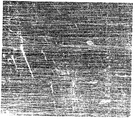
- a nanofiber array form close to a straight line is obtained as in the real picture shown in FIG.
- the nanofibers shown in FIG. 3C form a shape parallel to the circular motion trajectory of the spinning nozzle 20, and the degree of linearity and the degree of parallelism, that is, the degree of straightness or the degree of parallelism are proportional to the rotational speed.
- the nanofiber web generated by the circular motion of the spinning nozzle 20 as shown in FIG. 3b is a parallel shape shown in FIG. 3c or irregularly entangled as shown in FIG.
- the inner wall of the integrated plate 40 is provided with a base paper (F) for collecting the nanofibers discharged from the spinning nozzle 20 in the electric field between the spinning nozzle 20 and the integrated plate (40).
- the base paper F is provided to be movable in close contact with the inner wall of the integrated plate 40 along the circumferential direction of the rotation shaft 10.
- the integrated plate 40 is formed in an arc shape for the base paper entrance F1, and an air suction port 41 is formed at one side of the integrated plate 40 to collect the base paper F with negative air pressure. 40) is adsorbed on the inner wall.
- the base paper F is driven by the base plate conveying means 60 while the base paper F is absorbed by the integrated plate 40, the base paper F collects the nanofiber web along the inner wall of the integrated plate 40. Will move.
- the base paper F may be provided to be in close contact with the inner wall of the integrated plate 40 ′ along the axial direction of the rotation shaft 10 as shown in FIGS. 8 and 9.
- the integrated plate 40 ' is formed in a cylindrical shape.
- a guide member 45 is provided to roll the base paper F into an integrated plate 40' in an arc shape.
- the guide member 45 is a plate having a semicircular cross section and guides the base paper F to be rolled in the width direction when the base paper F enters the integrated plate 40 '.
- the guide member 45 and the base paper F are provided with one pair, and the guide member 45 is rolled through the cylindrical integrated plate 40 'in a semicircular shape, respectively.
- one side of the rotary shaft 10 is provided with a blowing fan 70 to allow the internal air of the integrated plate 40 'flows in a predetermined direction.
- the blowing fan 70 may be driven to allow air to flow in a direction in which the base paper F passes.
- the blowing fan 70 may be driven separately from the rotary shaft 10 by a separate driving unit.
- the high voltage generator 50 applies a high voltage to the polymer melt, which is electrically connected to the distribution passage 31 to apply electricity to the spinning nozzle 20 and the polymer melt, and the integrated plate 40 is grounded. Thus, a voltage difference is generated between the polymer melt discharged from the spinning nozzle 20 and an electric field is formed.
- Nanofiber web manufacturing method by rotating the spinning nozzle 20 around the rotating shaft 10 in the electric field to the nanofibers discharged from the spinning nozzle 20 spinning shaft 10 ) Is arranged in the circumferential direction.
- 3c discloses nanofibers arranged in the circumferential direction of the rotation shaft 10.
- the circular motion of the spinning nozzle 20 in the circumferential direction of the nanofibers formed in the circumferential direction of the rotating shaft 10 around the other rotation axis 10 to form a predetermined angle between the rotation axis 10 The polymer melt is discharged from the spinning nozzle 10 to form the nanofiber web in multiple layers, and the nanofibers in each layer are formed to form a predetermined angle with the nanofibers in the other layer.
- the nanofibers arranged in the circumferential direction of the rotary shaft 10 are disposed in a direction crossing the rotary shaft 10, and the polymer melt is discharged from the spinning nozzle furnace 20 on the surface of the nanofibers arranged in the circumferential direction.
- the nanofibers are discharged so that the nanofibers overlap with the nanofibers generated in the previous step to form a predetermined angle.
- the apparatus of FIG. 3 and the apparatus of FIG. 8 are mixed to prepare a double layer nanofiber web in a continuous process.
- the axis of rotation in the first electric field I and the axis of rotation in the second electric field II are arranged orthogonal to each other (to form an angle of 90 degrees).
- the spinning nozzle 20 is circumferentially rotated about the axis of rotation so that the first nanofibers N1 are arranged in the circumferential direction of the axis of rotation to generate a primary nanofiber web.
- the lattice-shaped nanofiber web has a small variation in the number of strands of the nanofibers distributed per unit area, and when the foreign matter including the conductive particles is fixed to the nanofibers, the distribution variation of the conductive particles can be significantly reduced. do.
- the angle between the first nanofiber N1 and the second nanofiber N2 is equal to the angle between the rotation axis in the first electric field I and the rotation axis in the second electric field II. That is, the angle between the xenon fibers N1 and the second nanofibers N2 varies according to the angle at which the rotation axis in the second electric field II is inclined with respect to the rotation axis in the first electric field I.
- the nanofiber web manufacturing apparatus according to an embodiment of the present invention, the rotating shaft 110, a rotating unit for rotating the rotating shaft 110 and the rotating shaft 110 transversely Spinning nozzle 130 for discharging the polymer melt in the direction of squeezing, an integration member 140 for forming an electric field in the space between the spinning nozzle 130, and nano-discharged formed into the electric field from the spinning nozzle 130
- a drawing unit 160 which pulls out fibers along the axial direction of the rotating shaft to form a tubular nanofiber web, and presses one side of the nanofiber web drawn out in tubular form by the extracting unit so as to be folded in two layers.
- the rotating shaft 110 is provided in the integrated member 140 to be axially rotated by a rotating unit.
- the rotary unit includes a drive motor 126 and transmits the power of the drive motor 126 to the rotating shaft 110 by the belt 127 and the pulley 128. Since the high voltage is applied to the rotating shaft 110 from the high voltage generator 180, power is transmitted to the belt 127 and the pulley 128 to block the high voltage from being applied to the driving motor 126. The high voltage applied to the rotating shaft 110 is transferred to the spinning nozzle 130 coupled to the outer circumferential surface of the rotating shaft 110 to implement electricity by applying electricity to the polymer melt in the spinning nozzle 130.
- the spinning nozzle 130 is provided so as to be circularly moved about the rotation shaft 110. That is, the spinning nozzle 130 is protruded in a cantilever shape to the outer circumferential surface of the rotary shaft 110 and screwed to have a circular motion about the rotary shaft 110 when the rotary shaft 110 rotates.
- the discharge flow path is formed in a direction crossing the rotation shaft 110 to discharge the polymer melt in a direction crossing the rotation shaft 110.
- a polymer melt supply passage 111 is formed inside the rotary shaft 110, and each of the spinning nozzles 130 is provided with a discharge passage communicating with the polymer melt supply passage 111 to accommodate the polymer melt. .
- the polymer melt is supplied from the polymer melt source 121 to the respective spinning nozzles 130 through the polymer melt supply passage 111 of the rotary shaft 110 and discharged to the outside of the spinning nozzle 130 through the respective discharge passages.
- the rotary shaft 110 has an air supply passage 113 for passing air from the outside, and a polymer melt supply passage 111 for passing the polymer melt from the polymer melt source 121. ) Is provided.
- the air supply passage 113 is located at the shaft center of the rotation shaft 110 and the polymer melt supply passage 111 is provided eccentrically at the shaft center.
- a ring-shaped rotary joint 122 is rotatably provided about the rotating shaft 110 on the outer circumferential surface of the rotating shaft 110 to transfer the polymer melt supplied from the polymer melt source 121 to the rotating shaft 110.
- a polymer melt inlet 112 is formed at one side of the polymer melt supply passage 111 of the rotary shaft 110, and the rotary joint 122 has a connection passage 122a communicating with the polymer melt inlet 112.
- a line coupling portion 122b connected to the melt supply line 121a from the polymer melt supply source 121.
- connection passage 122a of the rotary joint 122 is formed in a ring shape along the outer circumferential surface of the rotary shaft 110, so that the polymer melt can be supplied to the polymer melt inlet 112 even when the rotary shaft 110 is rotated. .
- the rotary joint 122 is rotated in the fixed state in the rotary shaft 122, the polymer melt supplied from the polymer melt supply source 121 to the line coupling portion 122b through the melt supply line 121a is It is supplied to the polymer melt inlet 112 along the outer circumferential surface of the rotating shaft 110 through the ring-shaped connecting passage 122a.
- the integration member 140 is provided in a cylindrical shape spaced apart from the front end of the radiation nozzle 130 at a predetermined distance and grounded. Accordingly, a potential difference is generated between the spinning nozzle 130 to which a high voltage is applied by the high voltage generator 180, and the polymer melt discharged from the spinning nozzle 130 is integrated along the radial direction of the rotary shaft 110. It is radiated toward 140. That is, a potential difference is generated between the integration member 140, the radiation nozzle 130, and the rotation shaft 110, so that an electric field is formed inside the cylindrical space, thereby performing electrospinning.
- the nanofibers discharged from the spinning nozzle 130 and radiated toward the integration member 140 are collected on the inner side of the integration member 140.
- the drawing unit includes a pulling member 151 which pulls the nanofiber web discharged from the spinning nozzle 130 and is collected in an annular shape along the axial direction of the rotation axis to form a tubular nanofiber web.
- the pulling member 151 of this embodiment is a winding roller which winds up and pulls the front end of the nanofiber web collected in an annular shape.
- the winding roller is only one example of the pulling member 151, and any means capable of pulling and transporting the nanofiber web is possible.
- the nanofibers are collected on the inner wall of the integration member 140.
- the nanofibers are formed as the spinning nozzle 130 moves in a circular motion, thereby forming an annular nanofiber web (N). ) Is formed.
- the radiation nozzles 130 are provided with a plurality of predetermined intervals along the axial direction of the rotary shaft 110, so that the annular nanofiber web (N) on the entire inner surface of the integration member 140
- the tubular nanofiber web is formed in a cylindrical shape, and when the pull member 151 pulls the tip of the nanofiber web N formed in a cylindrical shape, a tube-shaped nanofiber web is continuously made. In this way, it is possible to directly pull out the nanofiber web formed by being collected on the surface of the integration member 140, or it may be provided with a separate withdrawing means.
- the drawing unit collects the nanofibers discharged from the spinning nozzle 130 while moving along the axial direction of the rotating shaft 110 in the electric field. (52, 53, 54) may be further included.
- the collecting members 52, 53, and 54 are linearly formed like wires, threads, ropes, and belts, and transport the nanofiber webs while penetrating the electric field along the axial direction of the rotating shaft 110.
- the collecting member 152 is formed as a thread and is provided inside the integrated member 140, and a plurality of the collecting members 152 are provided at predetermined intervals along the circumferential direction of the integrated member 140. It is.
- the capturing member 152 composed of a thread passes through the interior of the integrated member 140 while being wound on the roller and is wound by the pulling member 151 to transport the tubular nanofiber web.
- the nanofiber web is collected on one side of the plurality of collecting members 152 to form a nanofiber web structure in which the plurality of collecting members 152 and the annular nanofiber web are integrally combined. That is, referring to the enlarged portion of FIG. 17 and FIG. 18, the nanofiber web structure is provided with a plurality of collecting members 152 made of thread with a predetermined distance from each other, and nanofibers are electrospun into the collecting member 152. It is fixed and combined. As such, when the collecting member 152 is moved in a state in which the plurality of collecting members 152 and the nanofiber web are integrally coupled, the nanofiber web can be transferred together with the collecting member 152.
- FIGS. 19 and 20 disclose another embodiment of the collecting member.
- the collecting member 153 shown in FIGS. 19 and 20 is provided to be movable in an endless orbital manner to transport the nanofiber web while moving by a predetermined distance with the nanofiber web. That is, the collecting member 153 of the present embodiment is moved together with the nanofiber web that is collected and coupled to one side, but is separated from the nanofiber web after passing through the integration member 140 to circulate in an orbital manner.
- the collecting member 154 illustrated in FIGS. 9 and 10 has a surface such as a film or a nonwoven fabric, and is introduced into the integrated member 140 in a dried state, and then collects and transports the nanofiber web. In this case, the nanofibers are collected on the inner side of the cylindrical collecting member 154 to form a tubular nanofiber web.
- the collecting member 154 is wound around the pulling member 151 while moving with the nanofiber web.
- the folding member 160 presses one side of the nanofiber web drawn out in a tubular shape by the drawing unit with a pair of rollers so as to be folded in two layers.
- the nanofiber web formed in a tubular shape is passed through the folding member 160 made of a pair of rollers, it is possible to obtain a nanofiber web in a double layered form.
- the nanofiber web is rolled through a plurality of rollers in an overlapped state, the physical properties of the nanofiber web can be improved. That is, when the tubular nanofiber web is superimposed, the nanofiber web can be easily tensioned through a rolling operation, thereby increasing the tensile strength.
- the guide member 170 is composed of a plurality of rollers to guide the inner diameter of the tubular nanofiber web is closer to the folding member 160, the narrower. That is, the guide members 170 composed of a plurality of rollers are provided with narrower gaps as they become closer to the folding member 160 in the integrated member 140 so that the tubular nanofiber webs can be easily folded. Guide to the folding member 160.
- the blowing unit includes an air supply passage 113 for supplying air to the inside of the nanofiber web so that the tubular nanofiber web is inflated, and an air supply source 124 forcibly supplying air to the air supply passage 113. And an air heater 125 for heating the air discharged from the air source 124.
- the air supply passage 113 is provided at one side of the rotation shaft 110.
- One end of the rotating shaft 110 is provided with a swivel joint 123 for supplying air to the air supply passage 113 of the rotating shaft 110 to rotate.
- the swivel joint 123 is supplied to the outside air to the air supply passage 113 while the rotating shaft 110 is rotated in a fixed state.
- the air supply passage 113 is formed through the rotation shaft 110, and one end of the rotation shaft 110 is provided with an air discharge port 113a through which air supplied to the air supply passage 113 is discharged. That is, the swivel joint 123 is coupled to one end of the rotation shaft 110 and the air discharge port 113a is formed at the other end.
- the air supply passage 113 of the rotary shaft 110 is supplied with high-temperature air, for this purpose, an air supply source 124 and an air heater 125 are provided. High pressure air is generated from the air supply source 124, and the high pressure air is heated to a high temperature by the air heater 125 and then supplied to the air supply passage 113 of the rotating shaft 110 through the swivel joint 123. And supplied into the nanofiber web through the air discharge port 113a.
- the hot air introduced into the tubular nanofiber web increases the tensile force of the nanofiber web by inflating the nanofiber web to increase its surface area.
- the hot air is passed through the nanofiber web to the outside to dry the nanofiber web, as well as to volatilize harmful solvents contained in the nanofiber web.
- Nanofiber web manufacturing method the collecting step of collecting the nanofibers in the annular in the electric field, to form a tubular nanofiber web of the nanofiber web formed in the annular in the collecting step Withdrawal step, folding step of superimposing the nanofiber web formed in the tubular shape in the withdrawal step in two layers, cutting step of manufacturing one layer of nanofiber web by cutting one side of the nanofiber web stacked in the folding step It includes.
- the polymer melt is discharged from the spinning nozzle 130 which is circularly moved about the rotation shaft 110 to form the nanofibers in an annular shape.
- the annular nanofiber web formed in an annular shape is transferred in the axial direction of the rotating shaft 110 to form a continuous tubular nanofiber web.
- the tubular nanofiber web can be continuously made.
- the blowing step of inflating the nanofiber web formed in a tubular shape in the drawing step is performed. That is, in the blowing step, the hot air is injected into the tubular nanofiber web to inflate the nanofiber web and volatilize the solvent while drying at high temperature.
- the superimposed nanofiber web is cut in the cutting step to obtain a flat nanofiber web.
- the tubular nanofiber web is pressed through a pair of rollers and overlapped in two layers.
- the extraction step is performed for the entire nanofiber web to extend the nanofiber web. That is, the folding step also serves to squeeze and hold the nanofiber web, so when one side of the nanofiber web is being folded, the nanofiber web is stretched and pulled out when the nanofiber web is pulled out with a winding roller. You lose.
- both ends or one end of the two-layered nanofiber web are continuously cut with a cutter. At this time, if both ends are cut, two nanofiber webs can be obtained, and once cut, two layers can be unfolded to obtain a wide nanofiber web of one sheet.
- the nanofiber web manufacturing apparatus it is possible to improve the physical properties by increasing the tensile force of the nanofiber web, to arrange the nanofibers in a predetermined direction, strands of nanofibers distributed per unit area
- the nanofiber web it is possible to produce a wide nanofiber web with a small number of nozzles.
- the nanofiber web can be easily dried.
Landscapes
- Engineering & Computer Science (AREA)
- Textile Engineering (AREA)
- Mechanical Engineering (AREA)
- Spinning Methods And Devices For Manufacturing Artificial Fibers (AREA)
- Nonwoven Fabrics (AREA)
Abstract
La présente invention concerne un appareil qui permet de préparer une bande de nanofibres et qui comporte : un arbre rotatif ; une pluralité de buses de filature disposées de manière circulaire de façon à pouvoir se déplacer autour de l'arbre rotatif ; une unité de rotation pour faire tourner axialement l'arbre rotatif ; une unité de distribution pour fournir une solution de polymère fondu à la pluralité de buses de filature ; une plaque intégrée de forme incurvée, espacée de l'extrémité avant des buses de filature à une distance prédéterminée ; un générateur de haute tension pour former un champ électrique dans un espace entre les buses de filature et la plaque intégrée. Il est possible d'améliorer des propriétés physiques en augmentant la force de tension d'une bande de nanofibres, d'agencer des nanofibres dans une certaine direction, et de préparer une bande de nanofibres de grande largeur avec un petit nombre de buses.
Priority Applications (1)
| Application Number | Priority Date | Filing Date | Title |
|---|---|---|---|
| CN201280064418.8A CN104053831A (zh) | 2011-12-30 | 2012-12-27 | 纳米纤维网制造装置及其方法 |
Applications Claiming Priority (6)
| Application Number | Priority Date | Filing Date | Title |
|---|---|---|---|
| KR10-2011-0147622 | 2011-12-30 | ||
| KR1020110147622A KR101343838B1 (ko) | 2011-12-30 | 2011-12-30 | 나노섬유웹 제조장치 |
| KR1020120049298A KR101415302B1 (ko) | 2012-05-09 | 2012-05-09 | 나노섬유웹 제조장치 및 방법 |
| KR10-2012-0049298 | 2012-05-09 | ||
| KR1020120100931A KR101415303B1 (ko) | 2012-09-12 | 2012-09-12 | 나노섬유웹 제조장치 및 방법 |
| KR10-2012-0100931 | 2012-09-12 |
Publications (1)
| Publication Number | Publication Date |
|---|---|
| WO2013100638A1 true WO2013100638A1 (fr) | 2013-07-04 |
Family
ID=48697984
Family Applications (1)
| Application Number | Title | Priority Date | Filing Date |
|---|---|---|---|
| PCT/KR2012/011589 WO2013100638A1 (fr) | 2011-12-30 | 2012-12-27 | Appareil et procédé pour préparer une bande de nanofibres |
Country Status (2)
| Country | Link |
|---|---|
| CN (1) | CN104053831A (fr) |
| WO (1) | WO2013100638A1 (fr) |
Cited By (3)
| Publication number | Priority date | Publication date | Assignee | Title |
|---|---|---|---|---|
| CN104711685A (zh) * | 2015-02-08 | 2015-06-17 | 福建师范大学 | 一种多功能静电纺丝设备 |
| CN107245764A (zh) * | 2017-08-01 | 2017-10-13 | 北京化工大学 | 一种离心微分静电纺丝法制备纳米纤维的装置 |
| WO2018100830A1 (fr) * | 2016-12-02 | 2018-06-07 | 株式会社 東芝 | Tête à buses et dispositif d'électrofilage |
Families Citing this family (7)
| Publication number | Priority date | Publication date | Assignee | Title |
|---|---|---|---|---|
| CN106087082B (zh) * | 2016-08-15 | 2018-04-20 | 青岛大学 | 一种离心纺丝装置 |
| CN108203880A (zh) * | 2017-12-28 | 2018-06-26 | 耐途隆株式会社 | 纤维的功能性物质吸附装置 |
| CN109097842B (zh) * | 2018-08-15 | 2021-04-20 | 湖南工程学院 | 一种聚合物静电纺丝接收网帘的制备方法 |
| CN111647959B (zh) * | 2020-07-10 | 2024-02-20 | 广东工业大学 | 一种基于在线算法的多针头式纺丝纤维制备装置及方法 |
| CN112011897B (zh) * | 2020-07-20 | 2022-06-07 | 福州法莫优科机械科技有限公司 | 一种适用于熔喷布生产的收集装置 |
| CN112680801B (zh) * | 2020-12-22 | 2021-11-23 | 江苏臻中滤料科技有限公司 | 一种用于空气过滤的无纺布生产装置及使用方法 |
| CN113584612A (zh) * | 2021-09-06 | 2021-11-02 | 北京化工大学 | 一种能沿两方向串联的连续熔融离心静电纺丝生产设备 |
Citations (6)
| Publication number | Priority date | Publication date | Assignee | Title |
|---|---|---|---|---|
| JP2001347590A (ja) * | 2000-06-09 | 2001-12-18 | Nippon Petrochem Co Ltd | 積層構造体、その製造方法および製造装置 |
| JP2002105830A (ja) * | 2000-09-29 | 2002-04-10 | Nippon Petrochem Co Ltd | 積層体の製造方法および製造装置 |
| KR20050094918A (ko) * | 2004-03-23 | 2005-09-29 | 김학용 | 상향식 전기방사장치 및 이를 이용하여 제조된 나노섬유 |
| KR20060079211A (ko) * | 2003-09-08 | 2006-07-05 | 테크니카 유니베르지타 브이 리베르치 | 정전방사를 이용한 고분자 용액으로부터 나노섬유 제조방법및 그 제조장치 |
| JP2007303015A (ja) * | 2006-05-10 | 2007-11-22 | Univ Of Shiga Prefecture | 静電紡糸装置 |
| JP4830992B2 (ja) * | 2006-07-05 | 2011-12-07 | パナソニック株式会社 | ナノファイバー及び高分子ウェブの製造方法と装置 |
Family Cites Families (1)
| Publication number | Priority date | Publication date | Assignee | Title |
|---|---|---|---|---|
| KR20090040872A (ko) * | 2006-07-05 | 2009-04-27 | 파나소닉 주식회사 | 나노 파이버 및 고분자 웹 제조방법과 그 장치 |
-
2012
- 2012-12-27 WO PCT/KR2012/011589 patent/WO2013100638A1/fr active Application Filing
- 2012-12-27 CN CN201280064418.8A patent/CN104053831A/zh active Pending
Patent Citations (6)
| Publication number | Priority date | Publication date | Assignee | Title |
|---|---|---|---|---|
| JP2001347590A (ja) * | 2000-06-09 | 2001-12-18 | Nippon Petrochem Co Ltd | 積層構造体、その製造方法および製造装置 |
| JP2002105830A (ja) * | 2000-09-29 | 2002-04-10 | Nippon Petrochem Co Ltd | 積層体の製造方法および製造装置 |
| KR20060079211A (ko) * | 2003-09-08 | 2006-07-05 | 테크니카 유니베르지타 브이 리베르치 | 정전방사를 이용한 고분자 용액으로부터 나노섬유 제조방법및 그 제조장치 |
| KR20050094918A (ko) * | 2004-03-23 | 2005-09-29 | 김학용 | 상향식 전기방사장치 및 이를 이용하여 제조된 나노섬유 |
| JP2007303015A (ja) * | 2006-05-10 | 2007-11-22 | Univ Of Shiga Prefecture | 静電紡糸装置 |
| JP4830992B2 (ja) * | 2006-07-05 | 2011-12-07 | パナソニック株式会社 | ナノファイバー及び高分子ウェブの製造方法と装置 |
Cited By (4)
| Publication number | Priority date | Publication date | Assignee | Title |
|---|---|---|---|---|
| CN104711685A (zh) * | 2015-02-08 | 2015-06-17 | 福建师范大学 | 一种多功能静电纺丝设备 |
| WO2018100830A1 (fr) * | 2016-12-02 | 2018-06-07 | 株式会社 東芝 | Tête à buses et dispositif d'électrofilage |
| JP2018090924A (ja) * | 2016-12-02 | 2018-06-14 | 株式会社東芝 | ノズルヘッド、および電界紡糸装置 |
| CN107245764A (zh) * | 2017-08-01 | 2017-10-13 | 北京化工大学 | 一种离心微分静电纺丝法制备纳米纤维的装置 |
Also Published As
| Publication number | Publication date |
|---|---|
| CN104053831A (zh) | 2014-09-17 |
Similar Documents
| Publication | Publication Date | Title |
|---|---|---|
| WO2013100638A1 (fr) | Appareil et procédé pour préparer une bande de nanofibres | |
| WO2014171625A1 (fr) | Appareil d'électro-filature | |
| CN103370457B (zh) | 纳米纤维制造装置 | |
| JP4981355B2 (ja) | 静電紡糸装置 | |
| JP4815310B2 (ja) | 静電紡糸不織布及び静電紡糸不織布の製造方法 | |
| JP5431461B2 (ja) | 溶融紡糸時にマルチフィラメント糸を引出しかつ延伸する方法並びにこの方法を実施する装置 | |
| KR20070047282A (ko) | 개량된 일렉트로블로잉 웹 형성 방법 | |
| JP5064087B2 (ja) | 長尺状静電紡糸不織布及び長尺状静電紡糸不織布の製造方法 | |
| CN214569593U (zh) | 熔喷布静电驻极加载装置及熔喷布驻极分切收卷生产线 | |
| WO2012087025A2 (fr) | Appareil de filage électrostatique comprenant un tube de filature ayant une pluralité de trous d'éjection | |
| CN214569543U (zh) | 熔喷布驻极分切收卷生产线 | |
| WO2014177039A1 (fr) | Dispositif et processus d'électrofilature à différentiel de fusion | |
| JP5178927B1 (ja) | ナノ・ファイバ製造装置 | |
| WO2012111930A2 (fr) | Appareil d'électrofilage et appareil pour la fabrication de nanofibres | |
| CN113891962B (zh) | 用于在制造纤维素非织造织物期间进行喷嘴清洗的方法和设备 | |
| CN111763995A (zh) | 一种应用于卷对卷式柔性基材的静电纺丝设备 | |
| WO2015076460A1 (fr) | Dispositif de filage électrostatique pour la fabrication de nanofibre | |
| CN110592689B (zh) | 一种利用离心纺和静电纺制备复合材料的设备 | |
| WO2012077871A1 (fr) | Dispositif pour la fabrication de nanofibres et dispositif d'apport d'air associé | |
| TWI547606B (zh) | 靜電紡絲的成束製造設備及其製造方法 | |
| JPH06220761A (ja) | 繊維の面状構成体を製造する方法と装置 | |
| KR101415303B1 (ko) | 나노섬유웹 제조장치 및 방법 | |
| CN112251868A (zh) | 一种连续制备纳米纤维包芯纱的装置及其方法 | |
| KR101343838B1 (ko) | 나노섬유웹 제조장치 | |
| WO2012077865A1 (fr) | Dispositif à émission de champ et dispositif de fabrication de nanofibres |
Legal Events
| Date | Code | Title | Description |
|---|---|---|---|
| 121 | Ep: the epo has been informed by wipo that ep was designated in this application |
Ref document number: 12863651 Country of ref document: EP Kind code of ref document: A1 |
|
| NENP | Non-entry into the national phase |
Ref country code: DE |
|
| 32PN | Ep: public notification in the ep bulletin as address of the adressee cannot be established |
Free format text: NOTING OF LOSS OF RIGHTS PURSUANT TO RULE 112 (1) EPC, EPO FORM 1205A DATED 05.09.14. |
|
| 122 | Ep: pct application non-entry in european phase |
Ref document number: 12863651 Country of ref document: EP Kind code of ref document: A1 |