WO2013100046A1 - 液面レベル計測装置、方法及びプログラム - Google Patents
液面レベル計測装置、方法及びプログラム Download PDFInfo
- Publication number
- WO2013100046A1 WO2013100046A1 PCT/JP2012/083855 JP2012083855W WO2013100046A1 WO 2013100046 A1 WO2013100046 A1 WO 2013100046A1 JP 2012083855 W JP2012083855 W JP 2012083855W WO 2013100046 A1 WO2013100046 A1 WO 2013100046A1
- Authority
- WO
- WIPO (PCT)
- Prior art keywords
- liquid
- ultrasonic
- gas
- container
- ultrasonic wave
- Prior art date
Links
Images


Classifications
-
- G—PHYSICS
- G01—MEASURING; TESTING
- G01F—MEASURING VOLUME, VOLUME FLOW, MASS FLOW OR LIQUID LEVEL; METERING BY VOLUME
- G01F23/00—Indicating or measuring liquid level or level of fluent solid material, e.g. indicating in terms of volume or indicating by means of an alarm
- G01F23/22—Indicating or measuring liquid level or level of fluent solid material, e.g. indicating in terms of volume or indicating by means of an alarm by measuring physical variables, other than linear dimensions, pressure or weight, dependent on the level to be measured, e.g. by difference of heat transfer of steam or water
- G01F23/28—Indicating or measuring liquid level or level of fluent solid material, e.g. indicating in terms of volume or indicating by means of an alarm by measuring physical variables, other than linear dimensions, pressure or weight, dependent on the level to be measured, e.g. by difference of heat transfer of steam or water by measuring the variations of parameters of electromagnetic or acoustic waves applied directly to the liquid or fluent solid material
- G01F23/296—Acoustic waves
- G01F23/2965—Measuring attenuation of transmitted waves
-
- F—MECHANICAL ENGINEERING; LIGHTING; HEATING; WEAPONS; BLASTING
- F01—MACHINES OR ENGINES IN GENERAL; ENGINE PLANTS IN GENERAL; STEAM ENGINES
- F01K—STEAM ENGINE PLANTS; STEAM ACCUMULATORS; ENGINE PLANTS NOT OTHERWISE PROVIDED FOR; ENGINES USING SPECIAL WORKING FLUIDS OR CYCLES
- F01K5/00—Plants characterised by use of means for storing steam in an alkali to increase steam pressure, e.g. of Honigmann or Koenemann type
- F01K5/02—Plants characterised by use of means for storing steam in an alkali to increase steam pressure, e.g. of Honigmann or Koenemann type used in regenerative installation
-
- G—PHYSICS
- G01—MEASURING; TESTING
- G01F—MEASURING VOLUME, VOLUME FLOW, MASS FLOW OR LIQUID LEVEL; METERING BY VOLUME
- G01F23/00—Indicating or measuring liquid level or level of fluent solid material, e.g. indicating in terms of volume or indicating by means of an alarm
- G01F23/22—Indicating or measuring liquid level or level of fluent solid material, e.g. indicating in terms of volume or indicating by means of an alarm by measuring physical variables, other than linear dimensions, pressure or weight, dependent on the level to be measured, e.g. by difference of heat transfer of steam or water
- G01F23/28—Indicating or measuring liquid level or level of fluent solid material, e.g. indicating in terms of volume or indicating by means of an alarm by measuring physical variables, other than linear dimensions, pressure or weight, dependent on the level to be measured, e.g. by difference of heat transfer of steam or water by measuring the variations of parameters of electromagnetic or acoustic waves applied directly to the liquid or fluent solid material
- G01F23/296—Acoustic waves
- G01F23/2961—Acoustic waves for discrete levels
-
- G—PHYSICS
- G01—MEASURING; TESTING
- G01F—MEASURING VOLUME, VOLUME FLOW, MASS FLOW OR LIQUID LEVEL; METERING BY VOLUME
- G01F23/00—Indicating or measuring liquid level or level of fluent solid material, e.g. indicating in terms of volume or indicating by means of an alarm
- G01F23/22—Indicating or measuring liquid level or level of fluent solid material, e.g. indicating in terms of volume or indicating by means of an alarm by measuring physical variables, other than linear dimensions, pressure or weight, dependent on the level to be measured, e.g. by difference of heat transfer of steam or water
- G01F23/28—Indicating or measuring liquid level or level of fluent solid material, e.g. indicating in terms of volume or indicating by means of an alarm by measuring physical variables, other than linear dimensions, pressure or weight, dependent on the level to be measured, e.g. by difference of heat transfer of steam or water by measuring the variations of parameters of electromagnetic or acoustic waves applied directly to the liquid or fluent solid material
- G01F23/296—Acoustic waves
- G01F23/2966—Acoustic waves making use of acoustical resonance or standing waves
- G01F23/2967—Acoustic waves making use of acoustical resonance or standing waves for discrete levels
-
- G—PHYSICS
- G01—MEASURING; TESTING
- G01F—MEASURING VOLUME, VOLUME FLOW, MASS FLOW OR LIQUID LEVEL; METERING BY VOLUME
- G01F23/00—Indicating or measuring liquid level or level of fluent solid material, e.g. indicating in terms of volume or indicating by means of an alarm
- G01F23/22—Indicating or measuring liquid level or level of fluent solid material, e.g. indicating in terms of volume or indicating by means of an alarm by measuring physical variables, other than linear dimensions, pressure or weight, dependent on the level to be measured, e.g. by difference of heat transfer of steam or water
- G01F23/28—Indicating or measuring liquid level or level of fluent solid material, e.g. indicating in terms of volume or indicating by means of an alarm by measuring physical variables, other than linear dimensions, pressure or weight, dependent on the level to be measured, e.g. by difference of heat transfer of steam or water by measuring the variations of parameters of electromagnetic or acoustic waves applied directly to the liquid or fluent solid material
- G01F23/296—Acoustic waves
- G01F23/2968—Transducers specially adapted for acoustic level indicators
-
- G—PHYSICS
- G21—NUCLEAR PHYSICS; NUCLEAR ENGINEERING
- G21C—NUCLEAR REACTORS
- G21C17/00—Monitoring; Testing ; Maintaining
- G21C17/02—Devices or arrangements for monitoring coolant or moderator
- G21C17/035—Moderator- or coolant-level detecting devices
-
- Y—GENERAL TAGGING OF NEW TECHNOLOGICAL DEVELOPMENTS; GENERAL TAGGING OF CROSS-SECTIONAL TECHNOLOGIES SPANNING OVER SEVERAL SECTIONS OF THE IPC; TECHNICAL SUBJECTS COVERED BY FORMER USPC CROSS-REFERENCE ART COLLECTIONS [XRACs] AND DIGESTS
- Y02—TECHNOLOGIES OR APPLICATIONS FOR MITIGATION OR ADAPTATION AGAINST CLIMATE CHANGE
- Y02E—REDUCTION OF GREENHOUSE GAS [GHG] EMISSIONS, RELATED TO ENERGY GENERATION, TRANSMISSION OR DISTRIBUTION
- Y02E30/00—Energy generation of nuclear origin
- Y02E30/30—Nuclear fission reactors
Definitions
- the present invention relates to a liquid level measurement technique for measuring the liquid level of a liquid contained in a container using ultrasonic waves.
- Liquid level measurement technology using ultrasonic waves is an ultrasonic sensor that is placed on the outer surface of a container that contains liquid, transmits ultrasonic waves, reflects the inner surface, and the intensity attenuation rate of echo waves received.
- a phenomenon that differs depending on whether the reflection point is in contact with the liquid or the gas is used. That is, the ultrasonic wave reflected from the interface between the gas and the container hardly attenuates, but the ultrasonic wave reflected from the interface between the liquid and the container is observed to be attenuated.
- a liquid level measurement is implemented by identifying whether each arrangement position of a plurality of ultrasonic sensors along the vertical direction of the inner surface of a container is adjacent to gas or liquid (for example, patent) References 1, 2).
- the present invention has been made in view of such circumstances, and provides a liquid level measurement technique capable of measuring the liquid level with high accuracy even when the liquid contained in the container is boiling. Objective.
- an ultrasonic sensor that is installed at a plurality of positions on the outer surface of a container that stores a liquid and that transmits and receives ultrasonic waves, and any one of the plurality of positions.
- a transmission / reception control unit for controlling transmission and reception of the ultrasonic wave, and an intensity of the ultrasonic wave satisfying at least 2 ⁇ N among the ultrasonic waves reflected N times (N: natural number) on the inner surface of the container
- An intensity detection unit that detects a point, a gas-liquid determination unit that determines whether a reflection point on the inner surface is in contact with the liquid or gas based on the detected intensity of the ultrasonic wave, and a superposition of the plurality of positions
- a level determination unit that determines a liquid level of the liquid based on a gas-liquid determination result derived from each of the acoustic wave sensors.
- the present invention provides a liquid level measurement technique capable of measuring the liquid level with high accuracy even when the liquid contained in the container is boiling.
- FIG. 1 is a block diagram showing a first embodiment of a liquid level measuring apparatus according to the present invention.
- the liquid level measuring device 10 of the first embodiment is disposed at a plurality of positions on the outer surface of a container 21 that contains a liquid 22 and transmits and receives ultrasonic waves.
- N natural number
- the vessel 21 is a reactor pressure vessel that contains reactor water (liquid 22).
- the container 21 to which the liquid level measuring device 10 of the embodiment is applied is not limited to such a reactor pressure vessel, but also a container having a high temperature and high humidity inside, a container filled with steam, and a liquid 22. It is applied to containers that generate voids, and containers placed in harsh environments such as high temperatures and high radiation fields. Examples of such containers include light water reactors, fast reactors, spent fuel pools, boilers such as steam generators, and various plants in the event of an accident.
- the ultrasonic sensor 15 (15 m ; 1 ⁇ m ⁇ M) is specifically composed of a heat-resistant vibrator such as lithium niobate, lithium tantalate, gallium phosphate, calcium bismuth titanate, or langasite. .
- a heat-resistant vibrator such as lithium niobate, lithium tantalate, gallium phosphate, calcium bismuth titanate, or langasite.
- the transmission efficiency of ultrasonic waves can be improved by sandwiching a contact medium such as a soft metal or gel.
- a contact medium such as a soft metal or gel.
- the ultrasonic sensor 15 can be installed at a plurality of positions on the outer surface of the container 21 by moving the single ultrasonic sensor 15.
- the ultrasonic sensor can apply the electromagnetic ultrasonic probe comprised from a magnet and a coil. According to this electromagnetic ultrasonic probe, it is possible to transmit and receive ultrasonic waves in a non-contact manner, and the attachment position with respect to the container 21 can be easily changed. In addition, longitudinal and transverse ultrasonic waves can be transmitted and received by adjusting the arrangement of magnets and coils. Further, when the material of the container 21 is a magnetized material, the electromagnetic ultrasonic probe (ultrasonic sensor 15) can be fixed by the attractive force of the constituent magnets. Further, there is no need to use a contact medium such as coplant or water, and no pretreatment is required. For this reason, the outer surface of the container 21 is not damaged, and can be attached to a painted surface or an oxidized corrosion surface.
- a contact medium such as coplant or water
- the transmission / reception control unit 11 includes a transmission circuit that transmits high voltage pulses to the ultrasonic sensor 15 at a constant repetition period, and a reception circuit that receives an echo signal transmitted from the transmission destination ultrasonic sensor 15. Yes.
- This transmission circuit generates high-voltage pulses having a waveform such as impulse, rectangular wave, triangular wave, sawtooth wave, etc., so that ultrasonic waves in a frequency range (several tens of kHz to several tens of MHz) in which propagation attenuation in the steel material is relatively small are generated.
- Send includes a transmission circuit that transmits high voltage pulses to the ultrasonic sensor 15 at a constant repetition period, and a reception circuit that receives an echo signal transmitted from the transmission destination ultrasonic sensor 15. Yes.
- This transmission circuit generates high-voltage pulses having a waveform such as impulse, rectangular wave, triangular wave, sawtooth wave, etc., so that ultrasonic waves in a frequency range (several tens of
- the reception control unit 11 for one of the ultrasonic sensor 15 m any of a plurality of positions, and the transmission and reception of ultrasonic waves, after the gas-liquid determination is made, another ultrasonic sensor 15 m
- the ultrasonic wave is transmitted and received in the same way for +1 .
- the intensity detector 12 is composed of an electronic circuit, and performs frequency filtering and voltage amplification on a signal waveform (see FIG. 6) output after the ultrasonic sensor 15 inputs an ultrasonic echo from the inner surface of the container. Determine the signal strength.
- the ultrasonic wave transmitted from the ultrasonic sensor 15 installed on the outer surface of the container 21 toward the inner surface is divided into a component that transmits the inner surface and a component that reflects the inner surface.
- the reflection component is divided into a component that is transmitted through the outer surface and detected by the ultrasonic sensor 15, and a component that is reflected again and travels toward the inner surface. Such reflection continues until the ultrasonic wave disappears due to attenuation or scattering, and ultrasonic echoes having various reflection times N with respect to the inner surface of the container are received by the ultrasonic sensor 15.
- the peak waveform of the echo signal shown in FIG. 6 corresponds to the case where the inner surface of the container 21 is reflected once, reflected twice,... N times sequentially from the left.
- the ultrasonic echo received by the ultrasonic sensor 15 has a high signal intensity when the reflection point on the inner surface of the container 21 is the gas 24, and has a low signal intensity when the reflection point is the liquid 22. Furthermore, the difference between the signal intensity in the air and in the liquid becomes more remarkable as the number of repetitions of reflection in the wall of the container 21 increases.
- the reflectance R on the inner surface and the outer surface is expressed by the following equation (1).
- the medium 1 is a steel material that forms the container 21, and the medium 2 is a coolant (liquid 22) or a gas 24 that is accommodated inside the container 21.
- Rw may be 0.97 or more.
- R (Z 1 ⁇ Z 2 ) / (Z 1 + Z 2 ) (1) (Z 1 : acoustic impedance of medium 1, Z 2 : acoustic impedance of medium 2)
- the intensity detector 12 in the first embodiment detects the signal intensity of the ultrasonic wave that satisfies 2 ⁇ N.
- the specific N value is experimentally selected to be a value at which a difference in signal intensity between the air and the liquid appears more remarkably and a sufficient S / N ratio can be secured.
- Such an ultrasonic signal intensity can be obtained by searching for the maximum value of echo signals acquired in time series.
- the time for detecting the signal intensity corresponding to each of the N reflections can be calculated from the propagation speed of the ultrasonic wave if the wall thickness and sound speed of the container 21 are known.
- the intensity of the echo signal acquired at the time obtained by such calculation can be set to the signal intensity corresponding to each of the N-time reflected ultrasonic echoes.
- the gas-liquid determination unit 13 determines whether the reflection point on the inner surface of the container 21 is in contact with the liquid 22 or the gas 24 based on the detected intensity of the ultrasonic echo. Specifically, since the propagation attenuation of the ultrasonic wave in the wall of the container 21 and the acoustic impedance of the steel material, the coolant, and the gas are known, the reflection point is in the air and liquid based on the equation (1). It is possible to analytically determine the signal intensity of echo waves of N reflections in both of them.
- the intensity detecting unit 12 matches the analysis value in liquid or in air, the one adjacent to the position of the corresponding ultrasonic sensor 15 is obtained. Whether it is a gas 24 or a liquid 22 is determined.
- the gas-liquid determination at the position of the focused ultrasonic sensor 15 is performed by comparing the signal intensity of the ultrasonic sensor 15 at other positions with the signal intensity relative to the detection value and the analysis value of the signal intensity as described above. It can be implemented by comparing. In this case, it can be recognized that the position where the signal intensity is relatively large is in the air, and the position where the signal intensity is small is in the liquid.
- the signal intensity of ultrasonic echoes of N reflections at the beginning of attachment of the ultrasonic sensor 15 is stored in advance. Then, the signal intensity of this N-time reflection is continuously detected in time series, and the detection value when changing from the air to the liquid is (Rw / Ra) N times, detection when the liquid is in the air It is recognized that the liquid level 23 is displaced by utilizing the fact that the value changes significantly as (Ra / Rw) N times.
- the level determination unit 14 determines the liquid level 23 based on the gas-liquid determination result derived from each of the ultrasonic sensors 15 m (1 ⁇ m ⁇ M) at a plurality of positions. In addition, the validity of the liquid level determination is confirmed based on the following protocol. (1) Regarding the determination results of the air determination and the liquid determination, the determination results are continuous, and the liquid determination and the air determination do not appear alternately. (2) The liquid determination does not appear above the air determination.
- the signal strength of the echo wave corresponding to the ultrasonic wave satisfying 2 ⁇ N among the ultrasonic waves received in this way is detected (S14). Based on the detected values it determines placement positions of the ultrasonic sensor 15 1 is adjacent to one of the liquid and gas (S15).
- the ultrasonic wave when the liquid level 23 is below the ultrasonic sensor 15 at the position of interest is reflected at the interface contacting the gas, the reflectivity is high, and the liquid level 23 is raised. In some cases, the ultrasonic wave is reflected on the interface in contact with the liquid, so that the reflectivity is low.
- the signal intensity of the echo wave may fluctuate due to the effects of vapor in the air or voids in the liquid, and the reflectance in the air and liquid may be slightly different.
- the difficulty of gas-liquid determination increases. However, according to each embodiment, the accuracy of the gas-liquid determination is maintained at a high level in order to examine the signal intensity of echo waves having a reflection count N of 2 or more.
- the liquid level measuring device 10 of the second embodiment has an ultrasonic attenuation coefficient based on the intensity attenuated by N reflections. Is provided with an attenuation coefficient deriving unit 18 for deriving.
- the gas-liquid determination unit 13 determines whether the reflection point on the inner surface is in contact with the liquid or the gas based on the attenuation coefficient. 3 that are the same as or correspond to those in FIG. 1 are denoted by the same reference numerals, and redundant description is omitted.
- the attenuation coefficient deriving unit 18 is composed of an electronic circuit, and performs frequency filtering and voltage amplification on the echo waveform output from the ultrasonic sensor 15. Then, as indicated by the broken line in FIG. 6, the attenuation coefficient of the attenuation curve connecting the peak points corresponding to each of the n-th reflection (1 ⁇ n ⁇ N) is obtained.
- This attenuation coefficient is larger when the reflection point is liquid (FIG. 6B) than when the reflection point is gas (FIG. 6A).
- the second embodiment in order to consider a plurality of echo waves of n times reflection (1 ⁇ n ⁇ N), the influence of the variation of a single echo wave is reduced. High accuracy is maintained.
- the liquid level measuring apparatus 10 of the third embodiment includes a pulse train generation unit 16 that generates ultrasonic waves composed of a plurality of pulse trains in addition to the configuration of the first embodiment (FIG. 1). Yes. Then, the transmission / reception control unit 11 causes the ultrasonic sensor 15 to transmit an ultrasonic wave composed of this pulse train. 4 that are the same as or correspond to those in FIG. 1 are denoted by the same reference numerals, and redundant description is omitted.
- the pulse train generation unit 16 can freely set the number of continuous waves p, and the waveform shape can be arbitrarily set such as a spike pulse shape or a rectangular wave shape.
- the gas-liquid determination is performed from the average value of the intensity of each pulse having the number of continuous waves p. As a result, since the influence of the variation of each pulse is reduced by averaging, the accuracy of the gas-liquid determination is highly maintained even when the liquid in the container is boiling.
- the liquid level measuring apparatus 10 of the third embodiment includes a frequency setting unit 17 that can set the frequency of the ultrasonic wave at the resonance point of the container 21. Then, the transmission / reception control unit 11 causes the ultrasonic sensor 15 to transmit an ultrasonic wave having a frequency set at the resonance point.
- the frequency setting unit 17 can set an ultrasonic frequency within a range of 10 kHz to several tens of MHz.
- the resonance frequency is a frequency at which the length of an integral multiple of the half wavelength of the ultrasonic wave matches the thickness of the container. Since the thickness of the reactor pressure vessel is approximately 100 to 300 mm, the lower limit of the set frequency is 10 kHz when longitudinal waves are used. On the other hand, the upper limit of the set frequency is a value that does not increase the influence of propagation attenuation in the steel material, and is approximately several tens of MHz.
- the frequency can be changed by changing the time width of the pulse voltage.
- the signal intensity of the ultrasonic wave received by the ultrasonic sensor 15 is significantly attenuated by reflection due to the resonance effect. As a result, even if the medium in contact with the inner surface of the container is a gas or a liquid and the respective reflectances are slightly different, the difference in the signal strengths appears remarkably by using ultrasonic waves at the resonance frequency.
- the transmission / reception control unit 11 of the liquid level measuring apparatus 10 causes the ultrasonic sensor 15 to transmit a broadband frequency ultrasonic wave including a resonance point.
- the transmission / reception control unit 11 can use the resonance frequency without adjusting the frequency, the frequency setting unit 17 is not necessary.
- the ultrasonic sensor 15 it is desirable to use a composite probe that can transmit and receive ultrasonic waves having a wide frequency bandwidth.
- the gas-liquid is based on the ultrasonic wave reflected and attenuated twice or more among the ultrasonic waves reflected multiple times between the inner surface and the outer surface of the container. Make a decision. This makes it possible to measure the liquid level formed by the liquid containing the void and the gas containing the vapor with high accuracy.
- the constituent elements of the liquid level measuring device can be realized by a computer processor, and a plurality of processors can be operated by a liquid level measuring program.
- 10 liquid level measuring device, 11 ... reception control unit, 12 ... intensity detecting unit, 13 ... liquid determination unit, 14 ... level determination section, 15 (15 1, 15 2 , 15 m, 15 M,) ... super Acoustic wave sensor, 16 ... pulse train generation unit, 17 ... frequency setting unit, 18 ... attenuation coefficient deriving unit, 21 ... container, 22 ... liquid, 23 ... liquid level, 24 ... gas.
Landscapes
- Physics & Mathematics (AREA)
- Engineering & Computer Science (AREA)
- Acoustics & Sound (AREA)
- Electromagnetism (AREA)
- Thermal Sciences (AREA)
- Fluid Mechanics (AREA)
- General Physics & Mathematics (AREA)
- General Engineering & Computer Science (AREA)
- Chemical & Material Sciences (AREA)
- Mechanical Engineering (AREA)
- Combustion & Propulsion (AREA)
- Plasma & Fusion (AREA)
- High Energy & Nuclear Physics (AREA)
- Measurement Of Levels Of Liquids Or Fluent Solid Materials (AREA)
Abstract
容器に収容した液体が沸騰していても、液面レベルを高精度に計測することができる液面レベル計測技術を提供する。 超音波の送信及び受信をする超音波センサ15(15m;1≦m≦M)と、これら複数の位置のうちいずれか一つの超音波センサ15を対象にして超音波の送信及び受信を制御する送受信制御部11と、容器21の内表面をN回反射(N:自然数)した超音波のうち少なくとも2≦Nを満たす超音波の強度を検出する強度検出部12と、この検出した超音波の強度に基づいて前記内表面における反射点が液体22及び気体24のいずれに接しているかを判定する気液判定部13と、複数の位置の超音波センサ15m(1≦m≦M)の各々から導かれた気液判定結果に基づいて液体の液面レベル23を判定するレベル判定部14と、を備える。
Description
本発明は、容器に収容される液体の液面レベルを、超音波を用いて計測する液面レベル計測技術に関する。
超音波を用いた液面レベル計測技術は、液体を収容する容器の外表面に超音波センサを配置して超音波を送信し、その内表面を反射して受信されたエコー波の強度減衰率が、その反射点が液体に接しているか気体に接しているかによって相違する現象を利用する。
つまり、気体と容器との界面を反射した超音波はほとんど減衰しないが、液体と容器との界面を反射した超音波は減衰が観測される。
そして、容器の内表面の天地方向に沿う複数の超音波センサの各々の配置位置が、気体及び液体のいずれに隣接するかを識別することで、液面レベル計測が実施される(例えば、特許文献1,2)。
つまり、気体と容器との界面を反射した超音波はほとんど減衰しないが、液体と容器との界面を反射した超音波は減衰が観測される。
そして、容器の内表面の天地方向に沿う複数の超音波センサの各々の配置位置が、気体及び液体のいずれに隣接するかを識別することで、液面レベル計測が実施される(例えば、特許文献1,2)。
ところが、上述した液面レベル計測技術では、容器に収容されている液体が沸騰している場合、気中の蒸気や液中のボイドの影響を受け、反射した超音波の強度減衰率が、時間および空間に依存して変動してしまう。このために、液面レベル計測の精度が低下する課題がある。
本発明はこのような事情を考慮してなされたもので、容器に収容した液体が沸騰していても、液面レベルを高精度に計測することができる液面レベル計測技術を提供することを目的とする。
液面レベル計測装置において、液体を収容する容器の外表面の複数の位置に設置されるとともに超音波の送信及び受信をする超音波センサと、前記複数の位置のうちいずれか一つの超音波センサを対象にして前記超音波の送信及び受信を制御する送受信制御部と、前記容器の内表面をN回反射(N:自然数)した前記超音波のうち少なくとも2≦Nを満たす前記超音波の強度を検出する強度検出部と、前記検出した超音波の強度に基づいて前記内表面における反射点が前記液体及び気体のいずれに接しているかを判定する気液判定部と、前記複数の位置の超音波センサの各々から導かれた気液判定結果に基づいて前記液体の液面レベルを判定するレベル判定部と、を備えることを特徴とする。
本発明により、容器に収容した液体が沸騰していても、液面レベルを高精度に計測することができる液面レベル計測技術が提供される。
(第1実施形態)
以下、本発明の実施形態を添付図面に基づいて説明する。
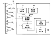
図1に示すように、第1実施形態の液面レベル計測装置10は、液体22を収容する容器21の外表面の複数の位置に設置されるとともに超音波の送信及び受信をする超音波センサ15(15m;1≦m≦M)と、これら複数の位置のうちいずれか一つの超音波センサ15を対象にして超音波の送信及び受信を制御する送受信制御部11と、容器21の内表面をN回反射(N:自然数)した超音波のうち少なくとも2≦Nを満たす超音波の強度を検出する強度検出部12と、この検出した超音波の強度に基づいて前記内表面における反射点が液体22及び気体24のいずれに接しているかを判定する気液判定部13と、複数の位置の超音波センサ15m(1≦m≦M)の各々から導かれた気液判定結果に基づいて液体の液面レベル23を判定するレベル判定部14と、を備えている。
以下、本発明の実施形態を添付図面に基づいて説明する。
図1に示すように、第1実施形態の液面レベル計測装置10は、液体22を収容する容器21の外表面の複数の位置に設置されるとともに超音波の送信及び受信をする超音波センサ15(15m;1≦m≦M)と、これら複数の位置のうちいずれか一つの超音波センサ15を対象にして超音波の送信及び受信を制御する送受信制御部11と、容器21の内表面をN回反射(N:自然数)した超音波のうち少なくとも2≦Nを満たす超音波の強度を検出する強度検出部12と、この検出した超音波の強度に基づいて前記内表面における反射点が液体22及び気体24のいずれに接しているかを判定する気液判定部13と、複数の位置の超音波センサ15m(1≦m≦M)の各々から導かれた気液判定結果に基づいて液体の液面レベル23を判定するレベル判定部14と、を備えている。
容器21は、炉水(液体22)を収容する原子炉圧力容器が示されている。しかし、実施形態の液面レベル計測装置10が適用される容器21は、このような原子炉圧力容器に限定されることなく、その他、内部が高温多湿の容器、蒸気が充満する容器、液体22にボイドが発生する容器、高温かつ高放射線場など苛酷環境に置かれた容器に適用される。このような容器として、例えば、軽水炉や高速炉、使用済み燃料プール、蒸気発生器などのボイラ、事故時の各種プラントなどが挙げられる。
超音波センサ15(15m;1≦m≦M)は、具体的に、ニオブ酸リチウム、タンタル酸リチウム、燐酸ガリウム、チタン酸カルシウムビスマス、ランガサイトなどの耐熱性を有する振動子から構成される。
このように耐熱性を有する振動子を適用することにより、炉心溶融等の過酷事故が発生した場合であっても、原子炉圧力容器の液面レベルを確実に計測することができる。
このように耐熱性を有する振動子を適用することにより、炉心溶融等の過酷事故が発生した場合であっても、原子炉圧力容器の液面レベルを確実に計測することができる。
超音波センサ15を容器21の外表面に固定する時は、軟らかい金属やジェル等の接触媒質を挟み込むことによって、超音波の伝達効率を向上させることができる。
なお、超音波センサ15m(1≦m≦M)の数量Mに制限はない。さらに、単数の超音波センサ15を移動させることにより、容器21の外表面の複数の位置に、この超音波センサ15を設置させることができる。
なお、超音波センサ15m(1≦m≦M)の数量Mに制限はない。さらに、単数の超音波センサ15を移動させることにより、容器21の外表面の複数の位置に、この超音波センサ15を設置させることができる。
また、超音波センサは、磁石とコイルから構成される電磁超音波探触子を適用することができる。この電磁超音波探触子によれば、超音波の送受信が非接触で可能で、容器21に対する取り付け位置の変更が容易になる。
また、磁石とコイルの配置を調整して縦波および横波の超音波を送受信することができる。また、容器21の材質が着磁性材料である場合は、構成要素の磁石の吸着力によって電磁超音波探触子(超音波センサ15)を固定することができる。また、カプラントや水などの接触媒質を用いる必要がなく、さらに前処理も不要である。このために、容器21の外表面を傷付けることがなく、塗装面や酸化腐食面にも取り付けることができる。
また、磁石とコイルの配置を調整して縦波および横波の超音波を送受信することができる。また、容器21の材質が着磁性材料である場合は、構成要素の磁石の吸着力によって電磁超音波探触子(超音波センサ15)を固定することができる。また、カプラントや水などの接触媒質を用いる必要がなく、さらに前処理も不要である。このために、容器21の外表面を傷付けることがなく、塗装面や酸化腐食面にも取り付けることができる。
送受信制御部11は、一定の繰り返し周期で高電圧パルスを超音波センサ15に送信する送信回路と、この送信先の超音波センサ15から送られるエコー信号を受信する受信回路と、から構成されている。
この送信回路は、インパルス、矩形波、三角波、鋸波などの波形を持つ高電圧パルスを、鋼材中の伝播減衰が比較的小さい周波数範囲(数10kHz~数10MHz)の超音波が発生するように送信する。
この送信回路は、インパルス、矩形波、三角波、鋸波などの波形を持つ高電圧パルスを、鋼材中の伝播減衰が比較的小さい周波数範囲(数10kHz~数10MHz)の超音波が発生するように送信する。
そして、この送受信制御部11は、複数の位置のうちいずれか一つの超音波センサ15mに対し、超音波の送信及び受信をし、気液判定がなされた後に、別の超音波センサ15m+1に対し超音波の送信及び受信を同様に行う。
強度検出部12は、電子回路から構成され、超音波センサ15が容器の内表面から超音波エコーを入力した後に出力する信号波形(図6参照)に対し、周波数フィルタリングと電圧増幅を行い、その信号強度を求める。
容器21の外表面に設置された超音波センサ15からその内表面に向かって送信された超音波は、この内表面を透過する成分と内表面を反射する成分とに分かれる。そして、この反射成分は、外表面を透過して超音波センサ15に検出される成分と、再び反射して内表面へ向かう成分とに分かれる。
このような反射は、超音波が減衰や散乱により消失するまで続き、容器の内表面に対する反射回数Nが多様な超音波エコーが超音波センサ15に受信される。
容器21の外表面に設置された超音波センサ15からその内表面に向かって送信された超音波は、この内表面を透過する成分と内表面を反射する成分とに分かれる。そして、この反射成分は、外表面を透過して超音波センサ15に検出される成分と、再び反射して内表面へ向かう成分とに分かれる。
このような反射は、超音波が減衰や散乱により消失するまで続き、容器の内表面に対する反射回数Nが多様な超音波エコーが超音波センサ15に受信される。
ここで、図6に示すエコー信号のピーク波形は、左から順番に、容器21の内表面を1回反射、2回反射、・・・N回反射したものに各々が対応している。
超音波センサ15で受信される超音波エコーは、容器21の内表面における反射点が気体24であるときは信号強度が大きく、この反射点が液体22であるときは信号強度が小さくなる。さらに、容器21の壁内における反射の繰り返し数が増すほど、気中時と液中の信号強度の違いがより顕著になる。
超音波センサ15で受信される超音波エコーは、容器21の内表面における反射点が気体24であるときは信号強度が大きく、この反射点が液体22であるときは信号強度が小さくなる。さらに、容器21の壁内における反射の繰り返し数が増すほど、気中時と液中の信号強度の違いがより顕著になる。
この理由について説明する。内表面や外表面における反射率Rは、次式(1)のように表される。ここで、媒質1は容器21を形成する鋼材であり、媒質2は容器21の内部に収容される冷却材(液体22)や気体24である。この媒質2が気体24の場合は反射率Ra=1で表され、冷却材(液体22)の場合は温度依存性を有するが概ね、Rw=0.94~0.97となる。ところで、冷却材(液体22)中にボイドが含まれる場合は、Rw=0.97以上になる場合がある。
R=(Z1-Z2)/(Z1+Z2) (1)
(Z1:媒質1の音響インピーダンス、Z2:媒質2の音響インピーダンス)
R=(Z1-Z2)/(Z1+Z2) (1)
(Z1:媒質1の音響インピーダンス、Z2:媒質2の音響インピーダンス)
そして、反射回数Nが増す毎に、超音波の反射点における媒質2が液体22である場合の信号強度と、気体24である場合の信号強度との相違は、(Ra/Rw)N倍となって顕著に現れる。
このために、第1実施形態における強度検出部12は、2≦Nを満たす超音波の信号強度を検出する。具体的なN値は、気中時と液中の信号強度の違いがより顕著に現れ、かつS/N比を充分に確保することができる値を実験的に選定する。
このために、第1実施形態における強度検出部12は、2≦Nを満たす超音波の信号強度を検出する。具体的なN値は、気中時と液中の信号強度の違いがより顕著に現れ、かつS/N比を充分に確保することができる値を実験的に選定する。
このような、超音波の信号強度は、時系列に取得したエコー信号の極大値をサーチすることにより求めることができる。
また一方で、N回反射の各々に対応する信号強度が検出される時間は、容器21の壁厚と音速が既知であれば、超音波の伝搬速度から計算することができる。このような計算により得た時間で取得したエコー信号の強度を、N回反射の超音波エコーの各々に対応する信号強度とすることができる。
また一方で、N回反射の各々に対応する信号強度が検出される時間は、容器21の壁厚と音速が既知であれば、超音波の伝搬速度から計算することができる。このような計算により得た時間で取得したエコー信号の強度を、N回反射の超音波エコーの各々に対応する信号強度とすることができる。
気液判定部13は、この検出した超音波エコーの強度に基づいて容器21の内表面における反射点が液体22及び気体24のいずれに接しているかを判定する。
具体的には、容器21の壁内の超音波の伝搬減衰や、鋼材、冷却材及び気体の音響インピーダンスが既知であることから、前記式(1)に基づいて、反射点が気中及び液中の両方におけるN回反射のエコー波の信号強度を解析的に求めることができる。
具体的には、容器21の壁内の超音波の伝搬減衰や、鋼材、冷却材及び気体の音響インピーダンスが既知であることから、前記式(1)に基づいて、反射点が気中及び液中の両方におけるN回反射のエコー波の信号強度を解析的に求めることができる。
そして、強度検出部12で得られた信号強度の検出値が、液中及び気中のいずれの解析値に合致するかを認定することにより、該当する超音波センサ15の位置に隣接するものが気体24であるか又は液体22であるかが判定される。
仮に、容器21に収容されている液体22が沸騰してボイドが存在したり、気体24に蒸気が存在したりする影響により、エコー波の信号強度の安定性が低い場合であっても、N回反射(2≦N)のエコー波の信号強度の差は顕著である。このために、N回反射(2≦N)のエコー波の信号強度の検出値が、気中及び液中のいずれの解析値に合致するかについての認定は容易である。
なお、着目する超音波センサ15の位置の気液判定は、上述したような信号強度の検出値と解析値とを照らし合わせる方法の他に、その他の位置の超音波センサ15の信号強度と相対比較することにより実施することができる。この場合、信号強度が相対的に大きい位置は気中、小さい位置は液中と認定できる。
また、その他の気液判定方法としては、超音波センサ15の取り付け当初におけるN回反射の超音波エコーの信号強度を予め記憶しておく。そして、このN回反射の信号強度を時系列的に検出し続け、気中から液中に変化した時の検出値が(Rw/Ra)N倍、液中から気中になった時の検出値が(Ra/Rw)N倍と顕著に変化することを利用して、液面レベル23が変位したことを認識する。
レベル判定部14は、複数の位置の超音波センサ15m(1≦m≦M)の各々から導かれた気液判定結果に基づいて液体の液面レベル23を判定する。
なお、液面レベル判定は、次のプロトコルに基づいてその妥当性を確認する。
(1)気中判定と液中判定の判定結果は、それぞれの判定結果が連続し、液中判定と気中判定が交互に現れることはない。
(2)液中判定が、気中判定より上側に現れることはない。
なお、液面レベル判定は、次のプロトコルに基づいてその妥当性を確認する。
(1)気中判定と液中判定の判定結果は、それぞれの判定結果が連続し、液中判定と気中判定が交互に現れることはない。
(2)液中判定が、気中判定より上側に現れることはない。
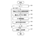
図2に基づいて各実施形態に係る液面レベル計測装置の動作を説明する(適宜図1参照)。
まず、複数の位置の超音波センサ15m(1≦m≦M)のうちいずれか一つ(m=1)を対象にする(S11)。そして、超音波センサ151から容器21に対して超音波を送信する(S12)。すると、この超音波は、容器21の内表面をN回反射(N:自然数)して、同じ超音波センサ151に受信される(S13)。
まず、複数の位置の超音波センサ15m(1≦m≦M)のうちいずれか一つ(m=1)を対象にする(S11)。そして、超音波センサ151から容器21に対して超音波を送信する(S12)。すると、この超音波は、容器21の内表面をN回反射(N:自然数)して、同じ超音波センサ151に受信される(S13)。
そして、このようにして受信された超音波のうち2≦Nを満たす超音波に対応するエコー波の信号強度を検出する(S14)。この検出値に基づいて超音波センサ151の配置位置が液体及び気体のいずれに隣接しているかを判定する(S15)。
この気液判定は、着目する位置の超音波センサ15よりも液面レベル23が下にある場合の超音波は気体に接する界面で反射するために反射率が高く、液面レベル23が上にある場合の超音波は液体に接する界面で反射するために反射率は低い、といった現象に基づいて行う。
一方、容器内が沸騰している場合は、気中の蒸気や液中のボイドの影響によりエコー波の信号強度が変動したり、気中と液中の反射率が僅差であったりすることから、気液判定の難易度が高くなる。しかし、各実施形態によれば、反射回数Nが2回以上のエコー波の信号強度を検討するために、気液判定の正確性が高度に維持される。
一方、容器内が沸騰している場合は、気中の蒸気や液中のボイドの影響によりエコー波の信号強度が変動したり、気中と液中の反射率が僅差であったりすることから、気液判定の難易度が高くなる。しかし、各実施形態によれば、反射回数Nが2回以上のエコー波の信号強度を検討するために、気液判定の正確性が高度に維持される。
次に、別の超音波センサ152を対象にして超音波を送信し(S16;No,S12)、同様に気液判定を繰り返す(S13~S15)。そして、最後の超音波センサ15Nに対する気液判定が終了したところで(S16;Yes)、全ての超音波センサ15m(1≦m≦M)の各々から導かれた気液判定結果に基づいて液面レベル23を判定する(S17)。
(第2実施形態)
図3に示すように、第2実施形態の液面レベル計測装置10は、第1実施形態の構成(図1)に加え、N回反射することにより減衰した強度に基づいて超音波の減衰係数を導出する減衰係数導出部18を備えている。
そして、気液判定部13は、この減衰係数に基づいて前記内表面における反射点が前記液体及び気体のいずれに接しているかを判定する。
なお、図3において図1と同一又は対応する部分は、同一符号で示し、重複する説明を省略する。
図3に示すように、第2実施形態の液面レベル計測装置10は、第1実施形態の構成(図1)に加え、N回反射することにより減衰した強度に基づいて超音波の減衰係数を導出する減衰係数導出部18を備えている。
そして、気液判定部13は、この減衰係数に基づいて前記内表面における反射点が前記液体及び気体のいずれに接しているかを判定する。
なお、図3において図1と同一又は対応する部分は、同一符号で示し、重複する説明を省略する。
この減衰係数導出部18は、電子回路から構成され、超音波センサ15が出力するエコー波形について周波数フィルタリングと電圧増幅を行う。
そして、図6の破線に示すように、n回反射(1≦n≦N)の各々に対応するピーク点を結ぶ減衰曲線の減衰係数を求める。
そして、図6の破線に示すように、n回反射(1≦n≦N)の各々に対応するピーク点を結ぶ減衰曲線の減衰係数を求める。
この減衰係数は、反射点が気体(図6(A))である場合よりも、液体(図6(B))である場合の方が、大きくなる。このように、超音波センサ15において受信される1回からN回までのエコー信号から求めた減衰曲線の減衰係数より、容器内が気中か液中かの判定が可能となる。
この第2実施形態によれば、n回反射(1≦n≦N)の複数のエコー波を考慮するために、単一のエコー波のバラツキの影響が軽減されるために、気液判定の正確性が高度に維持される。
この第2実施形態によれば、n回反射(1≦n≦N)の複数のエコー波を考慮するために、単一のエコー波のバラツキの影響が軽減されるために、気液判定の正確性が高度に維持される。
(第3実施形態)
図4に示すように、第3実施形態の液面レベル計測装置10は、第1実施形態の構成(図1)に加え、複数のパルス列からなる超音波を生成するパルス列生成部16を備えている。
そして、送受信制御部11は、このパルス列からなる超音波を超音波センサ15から送信させる。
なお、図4において図1と同一又は対応する部分は、同一符号で示し、重複する説明を省略する。
図4に示すように、第3実施形態の液面レベル計測装置10は、第1実施形態の構成(図1)に加え、複数のパルス列からなる超音波を生成するパルス列生成部16を備えている。
そして、送受信制御部11は、このパルス列からなる超音波を超音波センサ15から送信させる。
なお、図4において図1と同一又は対応する部分は、同一符号で示し、重複する説明を省略する。
一般的に送受信される超音波は、図5(A)に示すように、単パルスに近い波形を有するのに対し、第3実施形態においては、図5(B)に示すようなパルス列(連波数:p=10)からなる。
なお、パルス列生成部16において連波数pを自由設定できることとし、波形形状もスパイクパルス状、矩形波状等、任意設定することができる。
なお、パルス列生成部16において連波数pを自由設定できることとし、波形形状もスパイクパルス状、矩形波状等、任意設定することができる。
ここで、容器内が沸騰する場合には、気中の蒸気や液中のボイドの影響を受けてエコー波の信号強度の安定性が低下するため、気液判定精度の低下が懸念される。そこで、図5(B)に示される超音波パルス列を用い、連波数pの各パルスの強度の平均値から気液判定を実施する。
この結果、平均化により各パルスのバラツキの影響が軽減されるために、容器内の液体が沸騰している場合でも、気液判定の正確性が高度に維持される。
この結果、平均化により各パルスのバラツキの影響が軽減されるために、容器内の液体が沸騰している場合でも、気液判定の正確性が高度に維持される。
さらに第3実施形態の液面レベル計測装置10は、超音波の周波数を容器21の共振点に設定することができる周波数設定部17を備えている。
そして、送受信制御部11は、周波数が共振点に設定された超音波を超音波センサ15から送信させる。
そして、送受信制御部11は、周波数が共振点に設定された超音波を超音波センサ15から送信させる。
周波数設定部17は、10kHz~数10MHzの範囲内で超音波の周波数を設定することができる。ここで共振周波数とは、超音波の半波長の整数倍の長さと容器の厚みとが一致する周波数である。原子炉圧力容器の厚さが概ね100~300mmにあることから、設定周波数の下限は、縦波を用いた場合、10kHzとなる。一方、設定周波数の上限は、鋼材中の伝播減衰の影響が大きくならない程度の値で、概ね数10MHzになる。なお、周波数の変更は、パルス電圧の時間幅を変えることで可能である。
超音波センサ15で受信される超音波の信号強度は、共振効果によって、反射による信号強度の減衰が顕著になる。これによって、容器の内表面に接する媒体が気体又は液体であり各々の反射率が僅差であっても、共振周波数の超音波を用いることにより、各々の信号強度の差異が顕著に現れる。
さらに、連波数p=∞として、超音波センサ15から容器21へ連続した正弦波の超音波を送信することもできる。超音波は、容器の内表面と外表面の間で反射を繰り返し、外表面で反射する時に透過した超音波が超音波センサ15で受信される。
なお、他の実施形態における液面レベル計測装置10の送受信制御部11は、共振点を含む広帯域周波数の超音波を超音波センサ15から送信させる。
この場合の送受信制御部11は、周波数の調整をすることなく共振周波数を利用することができるために、周波数設定部17が不要となる。この場合、超音波センサ15として、周波数帯域幅の広い超音波を送受信できるコンポジット探触子などを用いることが望ましい。
この場合の送受信制御部11は、周波数の調整をすることなく共振周波数を利用することができるために、周波数設定部17が不要となる。この場合、超音波センサ15として、周波数帯域幅の広い超音波を送受信できるコンポジット探触子などを用いることが望ましい。
これにより、容器21の厚さに対応する共振周波数を含む広帯域超音波を送受信することができ、周波数の調整作業をすることなく、超音波の検出感度を増大させることができる。なお、共振点は一つではなく幾つも存在し、複数の共振点を含む広帯域周波数を選択することができる。
以上述べた少なくともひとつの実施形態の液面レベル計測装置によれば、容器の内表面と外表面の間で多重反射した超音波のうち二回以上反射して減衰した超音波に基づいて気液判定を実施する。これにより、ボイドを含む液体と蒸気を含む気体とによって形成される液面レベルを高精度に計測することが可能となる。
本発明のいくつかの実施形態を説明したが、これらの実施形態は、例として提示したものであり、発明の範囲を限定することは意図していない。これら実施形態は、その他の様々な形態で実施されることが可能であり、発明の要旨を逸脱しない範囲で、種々の省略、置き換え、変更、組み合わせを行うことができる。これら実施形態やその変形は、発明の範囲や要旨に含まれると同様に、特許請求の範囲に記載された発明とその均等の範囲に含まれるものである。
また、液面レベル計測装置の構成要素は、コンピュータのプロセッサで実現することも可能であり、複数のプロセッサを液面レベル計測プログラムにより動作させることが可能である。
10…液面レベル計測装置、11…送受信制御部、12…強度検出部、13…気液判定部、14…レベル判定部、15(151,152,15m,15M、)…超音波センサ、16…パルス列生成部、17…周波数設定部、18…減衰係数導出部、21…容器、22…液体、23…液面レベル、24…気体。
Claims (8)
- 液体を収容する容器の外表面の複数の位置に設置されるとともに超音波の送信及び受信をする超音波センサと、
前記複数の位置のうちいずれか一つの超音波センサを対象にして前記超音波の送信及び受信を制御する送受信制御部と、
前記容器の内表面をN回反射(N:自然数)した前記超音波のうち少なくとも2≦Nを満たす前記超音波の強度を検出する強度検出部と、
前記検出した超音波の強度に基づいて前記内表面における反射点が前記液体及び気体のいずれに接しているかを判定する気液判定部と、
前記複数の位置の超音波センサの各々から導かれた気液判定結果に基づいて前記液体の液面レベルを判定するレベル判定部と、を備えることを特徴とする液面レベル計測装置。 - 請求項1に記載の液面レベル計測装置において、
前記N回反射することにより減衰した強度に基づいて超音波の減衰係数を導出する減衰係数導出部を備え、
前記気液判定部は、前記減衰係数に基づいて前記内表面における反射点が前記液体及び気体のいずれに接しているかを判定することを特徴とする液面レベル計測装置。 - 請求項1に記載の液面レベル計測装置において、
複数のパルス列からなる超音波を生成するパルス列生成部を備え、
前記送受信制御部は、このパルス列からなる超音波を超音波センサから送信させることを特徴とする液面レベル計測装置。 - 請求項1に記載の液面レベル計測装置において、
前記超音波の周波数を前記容器の共振点に設定することができる周波数設定部を備え、
前記送受信制御部は、周波数が共振点に設定された超音波を超音波センサから送信させることを特徴とする液面レベル計測装置。 - 請求項1に記載の液面レベル計測装置において、
前記送受信制御部は、前記容器の共振点を含む広帯域周波数の超音波を超音波センサから送信させることを特徴とする液面レベル計測装置。 - 請求項1に記載の液面レベル計測装置において、
超音波センサは、磁石及びコイルから構成される電磁超音波探触子であることを特徴とする液面レベル計測装置。 - 液体を収容する容器の外表面の複数の位置に設置されるとともに超音波の送信及び受信をする超音波センサのうちいずれか一つを対象にして前記超音波の送信及び受信を制御するステップと、
前記容器の内表面をN回反射(N:自然数)した前記超音波のうち少なくとも2≦Nを満たす前記超音波の強度を検出するステップと、
前記検出した超音波の強度に基づいて前記内表面における反射点が前記液体及び気体のいずれに接しているかを判定するステップと、
前記複数の位置の超音波センサの各々から導かれた気液判定結果に基づいて前記液体の液面レベルを判定するステップと、を含むことを特徴とする液面レベル計測方法。 - コンピュータに、
液体を収容する容器の外表面の複数の位置に設置されるとともに超音波の送信及び受信をする超音波センサのうちいずれか一つを対象にして前記超音波の送信及び受信を制御するステップ、
前記容器の内表面をN回反射(N:自然数)した前記超音波のうち少なくとも2≦Nを満たす前記超音波の強度を検出するステップ、
前記検出した超音波の強度に基づいて前記内表面における反射点が前記液体及び気体のいずれに接しているかを判定するステップ、
前記複数の位置の超音波センサの各々から導かれた気液判定結果に基づいて前記液体の液面レベルを判定するステップ、を実行させることを特徴とする液面レベル計測プログラム。
Priority Applications (2)
| Application Number | Priority Date | Filing Date | Title |
|---|---|---|---|
| EP12861404.7A EP2799820B1 (en) | 2011-12-28 | 2012-12-27 | Liquid surface level measurement device, method, and program |
| US14/369,513 US9557208B2 (en) | 2011-12-28 | 2012-12-27 | Liquid level measuring apparatus, method, and program |
Applications Claiming Priority (2)
| Application Number | Priority Date | Filing Date | Title |
|---|---|---|---|
| JP2011-289625 | 2011-12-28 | ||
| JP2011289625A JP5774469B2 (ja) | 2011-12-28 | 2011-12-28 | 液面レベル計測装置、方法及びプログラム |
Publications (1)
| Publication Number | Publication Date |
|---|---|
| WO2013100046A1 true WO2013100046A1 (ja) | 2013-07-04 |
Family
ID=48697525
Family Applications (1)
| Application Number | Title | Priority Date | Filing Date |
|---|---|---|---|
| PCT/JP2012/083855 WO2013100046A1 (ja) | 2011-12-28 | 2012-12-27 | 液面レベル計測装置、方法及びプログラム |
Country Status (4)
| Country | Link |
|---|---|
| US (1) | US9557208B2 (ja) |
| EP (1) | EP2799820B1 (ja) |
| JP (1) | JP5774469B2 (ja) |
| WO (1) | WO2013100046A1 (ja) |
Cited By (1)
| Publication number | Priority date | Publication date | Assignee | Title |
|---|---|---|---|---|
| JP2017090401A (ja) * | 2015-11-17 | 2017-05-25 | 日立Geニュークリア・エナジー株式会社 | 原子炉水位推定装置 |
Families Citing this family (25)
| Publication number | Priority date | Publication date | Assignee | Title |
|---|---|---|---|---|
| JP2015052525A (ja) * | 2013-09-06 | 2015-03-19 | 株式会社東芝 | 液面レベルの計測装置及びその計測方法 |
| CN103528771B (zh) * | 2013-10-11 | 2015-11-18 | 广州供电局有限公司 | 一种测量电缆终端瓷套管漏油故障的方法 |
| US10168305B2 (en) * | 2013-10-17 | 2019-01-01 | Battelle Memorial Institute | Container screening system and method |
| US10724968B2 (en) | 2014-03-21 | 2020-07-28 | Battelle Memorial Institute | System and method for solution constituent and concentration identification |
| DE102014113470A1 (de) * | 2014-09-18 | 2016-03-24 | Maschinenfabrik Reinhausen Gmbh | Elektrogerät mit einem mit Isolieröl gefüllten Gehäuse sowie Messgerät und Verfahren zum Überwachen eines solchen Elektrogeräts |
| US20160320226A1 (en) * | 2015-04-30 | 2016-11-03 | Siemens Industry, Inc. | Determining height of a liquid level interface in a container from acoustic signal or echo time measurement |
| JP7151344B2 (ja) * | 2018-10-01 | 2022-10-12 | 富士電機株式会社 | 圧力計測装置 |
| DE102018218066A1 (de) * | 2018-10-22 | 2020-04-23 | Continental Automotive Gmbh | Verfahren und Vorrichtung zum Bestimmen des Füllstands und/oder der Qualität eines Fluids in einem Fluidbehälter |
| JP7206539B2 (ja) * | 2018-12-18 | 2023-01-18 | 株式会社竹中工務店 | コンクリート充填管理方法 |
| US10746716B1 (en) | 2019-05-31 | 2020-08-18 | Battelle Memorial Institute | System and method for solution constituent and concentration identification |
| US11231311B2 (en) | 2019-05-31 | 2022-01-25 | Perceptive Sensor Technologies Llc | Non-linear ultrasound method and apparatus for quantitative detection of materials |
| CN112325985B (zh) * | 2020-10-22 | 2021-09-07 | 北京卫星环境工程研究所 | 一种在轨航天器贮箱推进剂剩余量测量装置及方法 |
| US11729537B2 (en) | 2020-12-02 | 2023-08-15 | Perceptive Sensor Technologies, Inc. | Variable angle transducer interface block |
| WO2022120257A1 (en) | 2020-12-04 | 2022-06-09 | Perceptive Sensor Technologies, Inc. | Systems and methods for determining floating roof level tilt and characterizing runoff |
| CN116917729A (zh) * | 2020-12-04 | 2023-10-20 | 感知传感器技术股份有限公司 | 多路径声学信号在材料检测方面的改进 |
| US11604294B2 (en) | 2020-12-04 | 2023-03-14 | Perceptive Sensor Technologies, Inc. | Determining layer characteristics in multi-layered environments |
| WO2022120259A1 (en) | 2020-12-04 | 2022-06-09 | Perceptive Sensor Technologies, Inc. | Apparatus, system, and method for the detection of objects and activity within a container |
| US11788904B2 (en) | 2020-12-04 | 2023-10-17 | Perceptive Sensor Technologies, Inc. | Acoustic temperature measurement in layered environments |
| CN116829915A (zh) | 2020-12-04 | 2023-09-29 | 感知传感器技术股份有限公司 | 在分层环境中的声学温度测量 |
| US11994494B2 (en) * | 2020-12-04 | 2024-05-28 | Perceptive Sensor Technologies, Inc. | Multi-bounce acoustic signal material detection |
| US11536696B2 (en) | 2020-12-04 | 2022-12-27 | Perceptive Sensor Technologies, Inc. | In-wall multi-bounce material property detection and acoustic signal amplification |
| CN116888468A (zh) | 2020-12-30 | 2023-10-13 | 感知传感器技术股份有限公司 | 用信号评估流体质量 |
| CN113029292A (zh) * | 2021-03-19 | 2021-06-25 | 青海西钢自动化信息技术有限公司 | 一种超声波探测仪在轧机油气润滑中的应用 |
| WO2023154514A1 (en) | 2022-02-11 | 2023-08-17 | Perceptive Sensor Technologies, Inc. | Acoustic signal detection of material composition in static and dynamic conditions |
| US11940420B2 (en) | 2022-07-19 | 2024-03-26 | Perceptive Sensor Technologies, Inc. | Acoustic signal material identification with nanotube couplant |
Citations (7)
| Publication number | Priority date | Publication date | Assignee | Title |
|---|---|---|---|---|
| JPS559103A (en) * | 1978-07-05 | 1980-01-23 | Mitsubishi Heavy Ind Ltd | Level detecter at hopper of unhardened concrete |
| JPS61274223A (ja) * | 1985-05-30 | 1986-12-04 | Hitachi Constr Mach Co Ltd | 超音波による液槽内の液面検出方法 |
| JPH11218436A (ja) * | 1998-01-30 | 1999-08-10 | Toshiba Corp | 超音波液位計測装置 |
| JP2001194210A (ja) | 2000-01-14 | 2001-07-19 | Tokyo Electric Power Co Inc:The | 超音波液位計測装置 |
| JP2002340654A (ja) * | 2001-05-18 | 2002-11-27 | Hitachi Ltd | 音響による液位検出方法及び装置 |
| JP2003315030A (ja) * | 2002-04-22 | 2003-11-06 | Kinden Corp | 超音波計測センサ、超音波計測装置及び被計測対象の状態計測方法 |
| JP2008203204A (ja) * | 2007-02-22 | 2008-09-04 | Ricoh Elemex Corp | 液体検知装置 |
Family Cites Families (14)
| Publication number | Priority date | Publication date | Assignee | Title |
|---|---|---|---|---|
| US4203324A (en) * | 1977-08-05 | 1980-05-20 | Joseph Baumoel | Sonic liquid level detector |
| US4320659A (en) * | 1978-02-27 | 1982-03-23 | Panametrics, Inc. | Ultrasonic system for measuring fluid impedance or liquid level |
| DE3732219A1 (de) * | 1987-09-24 | 1989-04-13 | Siemens Ag | Anwendung des verfahrens zur elektromagnetischen ultraschall-wandlung zur ueberwachung von fuellhoehe und blasenbildung in fluessigkeit enthaltenden umschliessungen |
| US5195058A (en) * | 1992-04-30 | 1993-03-16 | The United States Of America As Represented By The Secretary Of The Air Force | Ultrasonic method for non-intrusive low liquid level sensing |
| JP3299655B2 (ja) * | 1995-03-17 | 2002-07-08 | 株式会社日立製作所 | 多層構造体の検査のための超音波探傷装置及びその超音波探傷方法 |
| US5880364A (en) * | 1997-10-31 | 1999-03-09 | Cosense, Inc. | Non-contact ultrasonic micromeasurement system |
| US6644114B1 (en) * | 1999-12-30 | 2003-11-11 | Mcewan Technologies, Llc | Direct PWM reflectometer |
| US6795015B2 (en) * | 2003-01-29 | 2004-09-21 | Saab Rosemount Tank Radar Ab | Bottom reflector for a radar-based level gauge |
| US7114390B2 (en) * | 2003-02-14 | 2006-10-03 | Adept Science & Technologies, Llc | Ultrasonic liquid level monitor |
| US6834546B2 (en) * | 2003-03-04 | 2004-12-28 | Saab Rosemount Tank Radar Ab | Device and method in a level gauging system |
| EP1921427B1 (en) * | 2006-11-07 | 2019-02-27 | LG Electronics Inc. | Automatic liquid dispensers with liquid level detector |
| US8167004B2 (en) * | 2007-02-14 | 2012-05-01 | Lg Electronics Inc. | Automatic liquid dispensers |
| US8069721B2 (en) * | 2007-05-16 | 2011-12-06 | Rosemount Tank Radar Ab | Radar level gauge system having limited transmission power |
| US9052230B2 (en) * | 2011-05-13 | 2015-06-09 | Chevron U.S.A. Inc | Industrial process monitoring and imaging |
-
2011
- 2011-12-28 JP JP2011289625A patent/JP5774469B2/ja active Active
-
2012
- 2012-12-27 US US14/369,513 patent/US9557208B2/en active Active
- 2012-12-27 EP EP12861404.7A patent/EP2799820B1/en not_active Not-in-force
- 2012-12-27 WO PCT/JP2012/083855 patent/WO2013100046A1/ja active Application Filing
Patent Citations (7)
| Publication number | Priority date | Publication date | Assignee | Title |
|---|---|---|---|---|
| JPS559103A (en) * | 1978-07-05 | 1980-01-23 | Mitsubishi Heavy Ind Ltd | Level detecter at hopper of unhardened concrete |
| JPS61274223A (ja) * | 1985-05-30 | 1986-12-04 | Hitachi Constr Mach Co Ltd | 超音波による液槽内の液面検出方法 |
| JPH11218436A (ja) * | 1998-01-30 | 1999-08-10 | Toshiba Corp | 超音波液位計測装置 |
| JP2001194210A (ja) | 2000-01-14 | 2001-07-19 | Tokyo Electric Power Co Inc:The | 超音波液位計測装置 |
| JP2002340654A (ja) * | 2001-05-18 | 2002-11-27 | Hitachi Ltd | 音響による液位検出方法及び装置 |
| JP2003315030A (ja) * | 2002-04-22 | 2003-11-06 | Kinden Corp | 超音波計測センサ、超音波計測装置及び被計測対象の状態計測方法 |
| JP2008203204A (ja) * | 2007-02-22 | 2008-09-04 | Ricoh Elemex Corp | 液体検知装置 |
Non-Patent Citations (1)
| Title |
|---|
| See also references of EP2799820A4 * |
Cited By (1)
| Publication number | Priority date | Publication date | Assignee | Title |
|---|---|---|---|---|
| JP2017090401A (ja) * | 2015-11-17 | 2017-05-25 | 日立Geニュークリア・エナジー株式会社 | 原子炉水位推定装置 |
Also Published As
| Publication number | Publication date |
|---|---|
| JP2013140029A (ja) | 2013-07-18 |
| US20140366626A1 (en) | 2014-12-18 |
| EP2799820B1 (en) | 2019-06-12 |
| US9557208B2 (en) | 2017-01-31 |
| EP2799820A1 (en) | 2014-11-05 |
| JP5774469B2 (ja) | 2015-09-09 |
| EP2799820A4 (en) | 2015-09-16 |
Similar Documents
| Publication | Publication Date | Title |
|---|---|---|
| JP5774469B2 (ja) | 液面レベル計測装置、方法及びプログラム | |
| EP2338047B1 (en) | Method and device for determining characteristics of a medium | |
| AU2011295676A1 (en) | Method for noninvasive determination of acoustic properties of fluids inside pipes | |
| NO327139B1 (no) | Fremgangsmate og system for bestemmelse av tap i materialtykkelse i en fast struktur | |
| JP4012237B2 (ja) | 配管検査方法及び装置 | |
| JP3913144B2 (ja) | 配管検査方法及び装置 | |
| Goujon et al. | Behaviour of acoustic emission sensors using broadband calibration techniques | |
| WO2015159378A1 (ja) | 超音波検査装置及び超音波検査方法 | |
| RU2580907C1 (ru) | Ультразвуковой волноводный уровнемер жидкости | |
| RU108627U1 (ru) | Система ультразвуковой дефектоскопии трубопровода | |
| JP2007064904A (ja) | 超音波による厚さ測定方法及びその装置 | |
| JP2008151705A (ja) | 超音波厚さ測定方法および装置 | |
| JP5940350B2 (ja) | 振動計測装置および振動計測方法 | |
| JP2011141236A (ja) | 減衰材の肉厚算出方法及びその装置 | |
| JP5059344B2 (ja) | 板厚測定装置および測定方法 | |
| JP2001343365A (ja) | 金属薄板の厚み共振スペクトル測定方法及び金属薄板の電磁超音波計測方法 | |
| JP2006084447A (ja) | 超音波非破壊計測方法及びそれに用いる超音波非破壊計測装置 | |
| Shannon et al. | Mode conversion and the path of acoustic energy in a partially water-filled aluminum tube | |
| RU2714868C1 (ru) | Способ обнаружения питтинговой коррозии | |
| EP1785701A1 (en) | Apparatus and method for determining a temperature of a volume of gas | |
| RU2437066C1 (ru) | Способ ультразвукового контроля уровня жидкости в резервуарах и устройство для ультразвукового контроля уровня жидкости в резервуарах | |
| US5122991A (en) | Distance measuring apparatus and method | |
| RU2540942C1 (ru) | Способ контроля за динамикой изменения толщины стенки контролируемого объекта | |
| US20100170343A1 (en) | Ultrasonic sensor and method for determining a separation of an object from an ultrasonic sensor | |
| EP4086620A1 (en) | Method and device for checking the wall of a pipeline for flaws |
Legal Events
| Date | Code | Title | Description |
|---|---|---|---|
| 121 | Ep: the epo has been informed by wipo that ep was designated in this application |
Ref document number: 12861404 Country of ref document: EP Kind code of ref document: A1 |
|
| WWE | Wipo information: entry into national phase |
Ref document number: 14369513 Country of ref document: US Ref document number: 2012861404 Country of ref document: EP |
|
| NENP | Non-entry into the national phase |
Ref country code: DE |