WO2013100016A1 - 給水装置 - Google Patents
給水装置 Download PDFInfo
- Publication number
- WO2013100016A1 WO2013100016A1 PCT/JP2012/083796 JP2012083796W WO2013100016A1 WO 2013100016 A1 WO2013100016 A1 WO 2013100016A1 JP 2012083796 W JP2012083796 W JP 2012083796W WO 2013100016 A1 WO2013100016 A1 WO 2013100016A1
- Authority
- WO
- WIPO (PCT)
- Prior art keywords
- cabinet
- guide plate
- heat sink
- water supply
- air guide
- Prior art date
- Legal status (The legal status is an assumption and is not a legal conclusion. Google has not performed a legal analysis and makes no representation as to the accuracy of the status listed.)
- Ceased
Links
Images



Classifications
-
- F—MECHANICAL ENGINEERING; LIGHTING; HEATING; WEAPONS; BLASTING
- F04—POSITIVE - DISPLACEMENT MACHINES FOR LIQUIDS; PUMPS FOR LIQUIDS OR ELASTIC FLUIDS
- F04D—NON-POSITIVE-DISPLACEMENT PUMPS
- F04D29/00—Details, component parts, or accessories
- F04D29/58—Cooling; Heating; Diminishing heat transfer
- F04D29/582—Cooling; Heating; Diminishing heat transfer specially adapted for elastic fluid pumps
-
- B—PERFORMING OPERATIONS; TRANSPORTING
- B67—OPENING, CLOSING OR CLEANING BOTTLES, JARS OR SIMILAR CONTAINERS; LIQUID HANDLING
- B67D—DISPENSING, DELIVERING OR TRANSFERRING LIQUIDS, NOT OTHERWISE PROVIDED FOR
- B67D1/00—Apparatus or devices for dispensing beverages on draught
- B67D1/08—Details
- B67D1/0857—Cooling arrangements
Definitions
- the present invention relates to a water supply apparatus including a pump and a motor housed in a cabinet, and more particularly to a water supply apparatus suitable for use in tap water supply in an apartment house or a building.
- a water supply device that is connected to a water main, for example, and pressurizes the water of the water main to a predetermined pressure to supply water to end users such as apartment buildings and buildings.
- This type of water supply apparatus includes a pump, piping connected to the suction side and discharge side of the casing of the pump, sensors such as a pressure sensor that detects pressure in the piping, a pressure tank, and the like. .
- a constant terminal pressure control system is adopted in order to keep the water supply water pressure at the end consumer at a predetermined pressure.
- the water supply apparatus includes a power source driving circuit such as an inverter device that supplies electric power to the motor, and an electric control circuit that controls the operation of the pump, in addition to the above-described pump and motor.
- a power source driving circuit such as an inverter device that supplies electric power to the motor
- an electric control circuit that controls the operation of the pump, in addition to the above-described pump and motor.
- Various parts and devices constituting these water supply devices are accommodated in a box-shaped cabinet formed of a metal plate such as stainless steel.
- the above-mentioned electrical parts include parts that generate heat when the water supply device is operated. For this reason, the temperature in the cabinet, particularly the temperature of the upper space in the cabinet, is likely to rise due to the heat generated by the electrical component. Since the cabinet itself is generally a casing made of a steel plate, for example, as a countermeasure for lowering the temperature in the cabinet of the water supply device while dissipating the heat in the cabinet from the surface to the outside air, for example, a water supply device shown in Patent Document 1 There is.
- a motor and a pump are arranged on the same rotation axis, and a fan is attached to the other end of the rotation axis of the motor.
- the fan is also rotated at the same time as the motor rotates.
- the cooled air in the lower part of the cabinet is blown to the upper inverter unit.
- the electrical components including the inverter device must be installed in the upper space in the cabinet from the viewpoint of avoiding water exposure, it is possible to effectively cool these electrical components.
- a cooling structure is required.
- the inverter case accommodating the inverter device in the upper space in the cabinet, for example, as close to the corner of the cabinet as possible.
- the gap between the surface of the inverter case and the inner wall of the cabinet is reduced.
- other parts are densely arranged around the inverter case, it is difficult for the air from the fan attached to the motor to flow through the gap between the inverter case and the inner wall of the cabinet. .
- the present invention has been made in view of the above-described points, and an object of the present invention is to form an air flow that can effectively suppress a local temperature rise in the cabinet with a simple configuration, and thereby in the cabinet.
- the object is to provide a water supply apparatus capable of optimizing the temperature distribution of each part.
- the present invention for solving the above problems includes a pump (11, 12) that pressurizes and feeds water, a motor (13, 14) that drives the pump (11, 12), and a motor (13, 14).
- a power supply drive circuit case (22) that is disposed above and houses a power supply drive circuit (23, 24) that supplies power to the motor (13, 14), a pump (11, 12), and a motor (13 , 14), a water supply device (1) comprising a cabinet (10) for accommodating a power supply drive circuit case (22), a heat sink (25) provided at a lower portion of the power supply drive circuit case (22), A fan (27, 28) that is attached to the upper end of the motor (13, 14) and that blows air toward the heat sink (25) by rotating by the operation of the motor (13, 14); Heat sink (2 ) Flows at or near at least one end (25b, 25c) of the heat sink (25) by the fan (27, 28), and exits from the end (25b, 25c) of the
- the air flow from the fan can also flow on the upper wall and upper side wall of the cabinet that has become hot due to solar radiation.
- heat on the surfaces of the upper wall and the side wall can be effectively removed.
- the heat sink (25) may include a heat radiation fin (25f) provided on the lower surface (22d) of the power supply circuit case (22).
- the radiating fins (25f) may extend toward the ends (25b, 25c) of the heat sink (25) where the air guide plates (32, 34) are installed. According to this configuration, the air flow from the fan toward the heat sink flows along the gaps of the fins and is reliably sent to the end of the heat sink, so that the air guided in the predetermined direction in the cabinet by the air guide plate A sufficient flow rate can be secured.
- the air guide plate (34) is arranged such that the air flow (F2) that has exited from the end (25c) of the heat sink (25) is guided downward in the cabinet (10). ) May be the lower guide air guide plate (34) installed with the surface (34d) on which the contact is directed downward (or obliquely downward). According to this configuration, the air flow from the end of the heat sink can be directed downward (lower space) in the cabinet, and a large air current circulating in a wide range in the vertical direction is formed in the cabinet. It is possible to suppress the variation in the temperature distribution.
- the air guide plate (32) has a surface (32d) against which the air flow (F1) is applied so that the air flow (F1) emitted from the end (25b) of the heat sink (25) is guided upward in the cabinet (10).
- the airflow flows along the gap between the power supply circuit case and the inner wall of the cabinet, that is, along the side wall (10b) and upper surface (10a) of the cabinet (10) and the outer surface of the inverter case (22).
- the heat of the surface of a cabinet (10) or an inverter case (22) can also be removed effectively.
- the airflow guide plates (32, 34) are arranged so that the airflow (F2) from one end (25c) of the heat sink (25) is guided downward in the cabinet (10).
- the lower induction wind guide plate (34) installed with the face (34d) facing downward and the air flow (F1) emitted from the other end (25b) of the heat sink (25) are in the cabinet (10).
- the pumps (11, 12), the motors (13, 14), and the power supply circuit case (22) are arranged at positions shifted from the center in the cabinet (10), so The distance between the side surface (22b) of the power source drive circuit case (22) on the side where the wind plate (32) is installed and the inner side surface (10b) of the cabinet (10) is the opposite side of the power source drive circuit case (22). The distance between the side surface (22c) and the inner side surface (10c) of the cabinet (10) is narrower, and the upper guide air guide plate (F2) is guided by the upper guide air guide plate (32).
- the gap between the power supply circuit case arranged at a position shifted from the center in the cabinet and the inner wall of the cabinet is often a narrow dimension.
- the present invention by providing the above-described upper guide air guide plate, it is possible to form an air flow in the narrow gap. For this reason, it can prevent that the local in a cabinet becomes high temperature by avoiding the temperature rise by retention of hot air.
- the pump (11, 12), the motor (13, 14), and the power supply drive circuit case (22) are arranged in the upper part when positioned at the approximate center in the cabinet (10).
- the air flow (F2) guided by the induction wind guide plate (32) is moved along the side surface (22b) and the upper surface (22a) of the power drive circuit case (22) on the side where the upper guide wind guide plate (32) is installed. It is advisable to install a flow path forming plate (36) for guiding.
- a flow path forming plate (36) for guiding.
- water pipes (16, 18) connected to the pumps (11, 12) may be installed inside the cabinet (10).
- the airflow can be cooled by heat exchange with the airflow flowing around the water pipe. Therefore, the temperature in the cabinet can be kept lower.
- the cooling action of the power supply circuit case by the heat sink increases and the temperature of the upper space in the cabinet decreases. Can also contribute.
- symbol in said parenthesis shows the code
- the temperature distribution of each part in the cabinet is optimized by forming an air flow that can effectively suppress a local temperature rise in the cabinet with a simple configuration. be able to.
- (A) is a perspective view which shows the detailed structure of the inverter case in a cabinet, and its periphery
- (b) is an enlarged view of Y part of (a). It is a figure for demonstrating the variation of the attachment structure of a baffle plate. It is a figure for demonstrating the flow and temperature distribution of the air in a cabinet. It is a front view which shows the water supply apparatus concerning 3rd Embodiment of this invention. It is a figure for demonstrating the flow and temperature distribution of the air in a cabinet. It is a front view which shows a part of water supply apparatus concerning 4th Embodiment of this invention. It is a front view which shows the structural example of the conventional water supply apparatus.
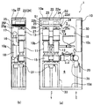
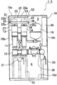
- FIG. 1 is a figure showing cabinet 10 of water supply apparatus 1 concerning a 1st embodiment of the present invention, and components stored in the inside.
- Fig.1 (a) is a front view
- FIG.1 (b) is a side view.
- the water supply apparatus 1 shown in FIG. 1 has two pumps 11 and 12 that pressurize and send water, motors 13 and 14 that drive the two pumps 11 and 12, and electric power to the motors 13 and 14.
- an inverter case (power supply drive circuit case) 22 that accommodates inverter devices (power supply drive circuits) 23 and 24, and the above pumps 11 and 12, motors 13 and 14, and inverter case 22 are accommodated.
- a cabinet 10 is provided.
- the cabinet 10 is made of a metal plate such as stainless steel, and is formed into a vertically long, substantially rectangular parallelepiped box shape by combining an upper wall 10a, left and right side walls 10b, 10c, a base 10d, and a rear wall 10g.
- the cabinet 10 has a horizontally long rectangular cross-sectional shape in plan view.
- the cabinet 10 of the water supply apparatus 1 and its internal components are viewed from the front as shown in FIG. Or it shall point down, right or left, or a horizontal direction.
- the longitudinal direction of the cabinet 10 refers to the longitudinal direction of the cross section (the left-right direction in FIG. 1A).
- the inverter devices (power supply drive circuits) 23 and 24 may include a DC reactor.
- a gantry 33 is installed in the lower space 6 in the cabinet 10.
- the lower space 6 here refers to the space below the pumps 11 and 12 in the cabinet 10.
- the gantry 33 is placed on the base 10 d of the cabinet 10, and various pipes and valves such as the pumps 11 and 12, the discharge header 17, and the suction header 15 are fixed to the gantry 33.
- the two pumps 11 and 12 are installed side by side on the gantry 33.
- those rotating shafts (not shown) are arrange
- the motor 13 and the pump 11 are installed on the same axis, and a cooling fan 27 is fixed to the upper end of the rotating shaft 13a of the motor 13 (see FIG. 2A).
- the motor 14 and the pump 12 are installed on the same axis, and a cooling fan 28 is fixed to the upper end of the rotating shaft 14a of the motor 14 (see FIG. 2A).
- the group consisting of the pump 11, the motor 13 and the fan 27 and the group consisting of the pump 12, the motor 14 and the fan 28 are configured so that either one of the groups is operated alternately. None drive.
- the motors 13 and 14 are, for example, DC brushless motors.
- the pumps 11 and 12 are, for example, multistage spiral pumps, and can employ a flow rate of 300 L / min and a total lift of about 70 m.
- the fans 27 and 28 are parts made of synthetic resin, for example, can be used with four blades, and preferably have a diameter of about 80 mm ⁇ .
- the fans 27 and 28 are directly fixed to the upper ends of the rotary shafts 13a and 14b of the motors 13 and 14, respectively. For this reason, compared to a separate air-cooled fan, there is no dedicated bearing or the like, so that it is extremely robust.
- the rotational speed of the fans 27 and 28 is substantially proportional to the amount of heat generated by the inverter devices 23 and 24.
- the fans 27 and 28 also rotate at high speed. Therefore, it is possible to send the cooling air in an amount commensurate (balanced) with the heat radiation amount of the motors 13 and 14 and the inverter devices 23 and 24 by the rotation of the fans 27 and 28.
- the suction ports of the pumps 11 and 12 are connected to the suction header 15, and the discharge ports of the pumps 11 and 12 are connected to the discharge header 17 through the discharge pipe 16.
- the discharge header 17 is provided above the pumps 11 and 12, and the water collected in the discharge header 17 passes through the discharge junction pipe 18 and the discharge valve 21, and is a piping pipe to the end consumer side (not shown). Connected to the road.
- a pressure tank 19 is installed on the side of the discharge header 17.
- the pressure tank 19 is connected to the discharge junction pipe 18.
- the pressure tank 19 has a function of accumulating (storing) pressurized water to prevent frequent start / stop of the pumps 11 and 12 and to keep the feed water pressure smoothly and constant.
- the suction header 15 is connected to a pipe line such as a water main pipe (not shown) via the backflow prevention device 35 and the suction valve 20.
- a control panel 30 is installed on the side of the pressure tank 19.
- the control panel 30 is attached along the inner surface of the side wall 10 c of the cabinet 10.
- the control panel 30 receives a signal from a pressure sensor that detects the pressure in the discharge header 17 and controls the pumps 11 and 12 to operate at a variable speed so that the feed water pressure at the end consumer becomes a predetermined pressure. Etc.
- an inverter case 22 containing the inverter devices 23 and 24 is installed in the upper space 5 in the cabinet 10.
- the upper space 5 is a space above the fans 27 and 28 in the cabinet 10 and refers to a space excluding the inside of equipment, parts, etc. in the cabinet 10.
- the inverter case 22 is a housing. Although it is not necessary to provide an opening on the side wall of the inverter case 22, it is preferable to provide a vent for promoting heat dissipation.
- 2A is a perspective view showing a detailed configuration of the inverter case 22 and its periphery
- FIG. 2B is a partially enlarged view of a portion X in FIG. 2A.
- the inverter case 22 is installed suspended from the upper wall 10a of the cabinet 10 in the upper space 5 in the cabinet 10 (illustration of the suspended structure is omitted).
- the inverter case 22 is installed in the vicinity of the upper left corner of the upper space 5 in the cabinet 10 and is arranged at a position shifted to the left side in the lateral direction as shown in FIG.
- a narrow gap S1 is formed between the left side surface 22b of the inverter case 22 and the side wall (inner wall) 10b of the cabinet 10 facing it, and the upper surface 22a of the inverter case 22 and the cabinet facing it.
- a narrow gap S2 is formed between the upper wall (inner wall) 10a.
- the inverter devices 23 and 24 accommodated in the inverter case 22 enable the motors 13 and 14 by supplying AC power of variable frequency and variable voltage to the motors 13 and 14 via a cable (not shown). Variable speed drive.
- the inverter devices 23 and 24 those having a capacity combined with the capacity of the motors 13 and 14 are employed. Since the inverter devices 23 and 24 are devices that generate heat when the motors 13 and 14 are driven, the internal temperatures of the inverter devices 23 and 24 and the inverter case 22 rise to a high temperature.
- a heat sink 25 is attached to the lower surface 22 d of the inverter case 22.
- the heat sink 25 is made of, for example, a metal having high thermal conductivity such as aluminum, and a plurality of radiating fins 25f are arranged at equal intervals on the lower surface (the surface facing the fans 27 and 28).
- a large number of grooves 25g extending in parallel with each other are formed between the heat radiating fins 25f.
- the heat radiation fin 25f extends from one end 25b to the other end 25c along the longitudinal direction (left-right direction) of the heat sink 25, and the groove 25g penetrates both ends 25b and 25c of the heat sink 25. Yes.
- both ends in the longitudinal direction of the heat dissipating fins 25f are aligned with both end positions of the lower surface 22d of the power supply circuit case 22.
- a plurality of rectangular plate-like members are preferably used for the fins 25f.
- the heat sink 25 is disposed above the motors 13 and 14 and the fans 27 and 28 on the extension line of the rotating shafts 13a and 14a of the motors 13 and 14 (directly above the axis). Therefore, the air blown by the rotation of the fans 27 and 28 strikes the lower surface side of the heat sink 25. Thus, the blown air flows in the groove 25g of the heat sink 25 toward the end portions 25b and 25c on both sides.
- the water supply apparatus 1 of this embodiment is provided with the baffle plate (downward induction
- the air guide plate 34 is made of a rectangular plate material made of metal or synthetic resin, and the base side end side is attached to the lower surface 22d side (upper end side) of the inverter case 22 at the end portion 25c of the heat sink 25.
- the heat sink 25 extends downward from the end 25c.
- the base side end of the air guide plate 34 is connected to a position corresponding to the base of the heat radiating fin 25 f (the bottom of the groove 25 g) at the end 25 c of the heat sink 25.
- the air guide plate 34 and the heat radiating fins 25f are attached so that their surfaces are substantially orthogonal to each other. Therefore, the air guide plate 34 is installed in an inclined state so that a surface (inner surface) 34d (see FIG. 2B) on which the airflow from the end portion 25c of the heat sink 25 hits faces downward. Further, the length L1 of the air guide plate 34 (see FIG. 2B) is such that the tip of the air guide plate 34 reaches a height equal to or lower than the lower end of the heat sink 25, as shown in FIGS. It is good to set to such a dimension. Further, the width dimension (depth dimension) L2 (see FIG.
- the air guide plate 34 only needs to be a dimension that allows the air blown from the fans 27 and 28 to pass through the groove 25g of the heat sink 25, and this embodiment. Then, as shown in FIG.1 (b), it is set to the dimension about 2/3 of the depth dimension of the inverter case 22.
- FIG. 2B the air guide plate 34 has an angle ⁇ formed by the inner surface 34d and the lower surface 22d of the inverter case 22 (or the upper surface of the heat sink 25) of 90 degrees or more and less than 180 degrees (that is, 90 [deg.] ⁇ [Alpha] ⁇ 180 [deg.]. More preferably, it is attached so that ⁇ is an angle within a range of 100 degrees to 150 degrees.
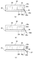
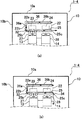
- FIG. 3 is a diagram for explaining variations of the mounting structure of the air guide plate 34.
- the air guide plate 34 can be directly attached to the end portion 25 c of the heat sink 25.
- the base side end of the air guide plate 34 may be attached so as to be connected to the base portion of the fin 25f or the bottom portion of the groove portion 25g.
- another mounting structure of the air guide plate 34 as shown in FIG. 3B, it can be attached to the side surface 22c of the inverter case 22 and extended to a position facing the end portion 25c of the heat sink 25. .
- the base side end of the air guide plate 34 may be attached on the boundary line between the lower surface 22 d of the inverter case 22 and the heat sink 25.
- the air guide plate 34 can be attached to another component 37 in the cabinet 10 that faces the end portion 25 c of the heat sink 25.
- the front end portion of the air guide plate 34 may be provided so as to contact the end portion 25c of the heat sink 25, or the front end portion may be disposed at a position slightly away from the end portion 25c of the heat sink 25. May be provided.
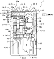
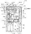
- FIG. 4 is a view for explaining the air flow and temperature distribution in the cabinet 10 in the water supply apparatus 1 of the present embodiment.
- FIG. 4 shows the temperature distribution of each part (point A to point O in FIG. 4) in the cabinet 10 when the water supply apparatus 1 is operated. Further, the numbers shown in parentheses corresponding to the points A to O are compared with the temperatures at the same place measured in the cabinet 10 of the conventional water supply apparatus 100 (FIG. 12) without the air guide plate 34. The temperature difference is shown.
- the position of each of points A to O will be outlined. Point A is the space between the side wall 10b of the cabinet 10 and the side surface 22b of the inverter case 22 (gap S1), and point B is the upper wall of the cabinet 10.
- point C is the space below the inverter case 22
- point D is the space above the pressure tank 19
- point E is the pressure tank 19
- Point F is the space between the pump 11 and the pump 12
- point G is the space between the side wall 10b of the cabinet 10 and the pump 11
- point H is the space below the suction header 15, I
- the point is the left side in the lower space 6 in the cabinet 10
- the point J is the space below the backflow prevention device 35
- point K is the right side in the lower space 6 in the cabinet 10
- point L is the upper wall 1 of the cabinet 10.
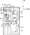
- FIG. 12 is a diagram illustrating a configuration example of a conventional water supply apparatus 100 in which the air guide plate 34 is not provided.
- symbol is attached
- the main heat generating portion heat generating component
- the temperature distribution in the cabinet 10 is such that the temperature in the upper space 5 is the highest and the temperature is lower as it goes downward. It was presenting. Then, as shown in FIG. 12, the air heated to high temperature by heat exchange by the heat sink 25 exits from the end 25c of the heat sink 25 and flows substantially horizontally toward the right side in the cabinet 10 (air flow F2 ′). Therefore, the high temperature air stayed in the upper space 5 in the cabinet 10 and the vicinity thereof.
- the air flow F ⁇ b> 3 is cooled by a water passing portion such as the pump 11 and the surrounding piping, and enters the fan 27 through the outer peripheral portion of the motor 13. Then, the air blown out from the fan 27 again hits the heat radiating fins 25 f of the heat sink 25. Therefore, the outer periphery of the motor 13 is cooled by the cooled air, and the heat sink 25 is cooled.
- the conventional airflow F2 ′ is not generated, and the air heated by heat exchange with the heat sink 25 does not stay in the upper space 5 in the cabinet 10. For this reason, warmed air can escape to the lower space 6 in the cabinet 10.
- the air flow F ⁇ b> 3 whose direction is changed by the air guide plate 34 flows downward in the cabinet 10.
- the air flow F1 exiting from the other end 25b of the heat sink 25 is also caused by the gap S1 between the side wall 10b of the cabinet 10 and the side surface 22b of the inverter case 22, and the upper wall 10a of the cabinet 10 and the upper surface 22a of the inverter case 22.
- the air flow F4 is generated more easily and smoothly through the gap S2.
- the downward air guide plate 34 is installed at the end 25 c of the heat sink 25.
- the high-temperature air flow F ⁇ b> 2 coming out from the end portion 25 c of the heat sink 25 is not changed to the air flow F ⁇ b> 2 ′ that flows directly to the right side in the cabinet 10, but the direction is changed by the air guide plate.
- the airflow F3 that flows downward is generated.
- the air flow F ⁇ b> 3 flows by involving cooler air in the lower space 6 in the cabinet 10.
- the air flow F ⁇ b> 3 again passes around the water passage portion, and then circulates in a flow path sucked into the fan 27 through the outer periphery of the pump 11 and the motor 13.
- the large airflow F3 which circulates the whole inside of the cabinet 10 is formed by descending the approximate center in the cabinet 10 from the heat sink 25 through the air guide plate 34.
- the heat sink 25 is heat-exchanged with air having a temperature lower than that of the conventional heat flow F3.
- the efficiency of heat exchange by the heat sink 25 can be increased as compared with the water supply apparatus 100 having a conventional structure. For this reason, it is possible to more effectively remove the heat generated by the inverter devices 23 and 24 in the inverter case 22. Therefore, the temperature in the inverter case 22 decreases. In addition, since the amount of heat transfer from the inverter case 22 to the upper side decreases, the ambient temperature in the gaps S1 and S2 between the inverter case 22 and the cabinet 10 decreases.
- the low-temperature air entrains the air at the right corner in the cabinet 10 and flows again from the lower space 6 of the cabinet 10 to the motor 13. Due to one or both of the first and second effects, the retention of hot air in the upper space 5 in the cabinet 10 is eliminated, and the temperature deviation in the cabinet 10 is improved.
- an airflow that circulates greatly in the cabinet 10 shown in FIG. 4 can be formed by the airflow whose direction is changed by the air guide plate 34.
- the air in the cabinet 10 is smoothly stirred. This can prevent hot air from staying locally in the upper space 5 in the cabinet 10, the temperature of the upper space 5 in the cabinet 10, the temperature of the electrical components installed in the upper space 5, and Both the surface temperatures of the side wall 10b and the upper wall 10a of the cabinet 10 can be lowered.
- the air guide plate 34 optimizes the electrical components including the inverter devices 23 and 24 disposed in the upper portion of the cabinet 10 and the surrounding temperature environment without separately providing a new air cooling mechanism.
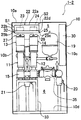
- FIG. 5 is a front view showing a water supply device 1-2 according to the second embodiment of the present invention.
- FIG. 6A is a partially enlarged perspective view showing a detailed configuration of the inverter case 22 provided in the water supply device 1-2 of the second embodiment and its periphery
- FIG. 6B is a diagram of FIG. 6A. It is the elements on larger scale of Y part.
- the air guide plate 34 instead of the air guide plate 34 provided in the water supply device 1 of the first embodiment, the end portion of the heat sink 25 opposite to the end portion 25c provided with the air guide plate 34 ( Another wind guide plate (upper guide wind guide plate) 32 attached to the other end 25b is provided. As shown in FIG.
- the air guide plate 32 has two rectangular flat plate portions 32a and 32b that are integrally connected to both sides of the intermediate bent portion 32c. Is a plate-like member formed in a substantially L-shape.
- an angle ⁇ formed with respect to the flat plate portion 32a is set to an angle of about 120 degrees as an example.
- the air guide plate 32 of the present embodiment is formed as a plate material made of metal or synthetic resin.
- the air guide plate 32 may be formed by integrally molding two flat plate portions 32a and 32b, or has a configuration in which two flat plate portions 32a and 32b formed separately are connected by a bent portion 32c. Also good.
- One flat plate portion 32 a of the air guide plate 32 is attached to the lower end (tip) of each radiation fin 25 f on the end 25 b side of the radiation fin 25 f formed on the heat sink 25.
- the flat plate portion 32 b is arranged in parallel with the lower surface 22 d of the inverter case 22 and the lower surface of the heat sink 25.
- the bent portion 32 c of the air guide plate 32 is arranged in accordance with the end portion 25 b of the heat sink 25.
- the other flat plate portion 32a is connected to the flat plate portion 32b at an angle of about 120 degrees at the bent portion 32c.
- the other flat plate portion 32a extends outward from the bent portion 32c (upwardly to the left in the drawing).
- the inner surface 32d of the flat plate part 32a which the airflow which came out from the edge part 25b of the heat sink 25 hits is arrange
- the width dimension (depth dimension) L3 of the air guide plate 32 is formed to be about 2/3 of the depth dimension of the inverter case 22 as in the case of the air guide plate 34 of the first embodiment.
- FIG. 7 is a diagram for explaining variations of the mounting structure of the air guide plate 32.
- the air guide plate 32 can be directly attached to the end 25b of the heat sink 25 as shown in FIG.
- the flat plate portion 32b of the air guide plate 32 is attached to the end portion 25b of the heat sink 25 where the air from the fan 27 does not directly collide with the heat sink 25 and the vicinity thereof.
- the front end of the flat plate portion 32 a is disposed to face the side wall 10 b of the cabinet 10 with a slight gap.
- the tip of the flat plate portion 32 a in contact with the side wall 10 b of the cabinet 10.
- the tip of the flat plate portion 32b should be in contact with the side wall 10b of the cabinet 10 without any gap. desirable.
- the air guide plate 32 As another attachment structure of the air guide plate 32, as shown in FIG. 7B, it can be attached to the side wall 10b of the cabinet 10 arranged to face the end 25b of the heat sink 25. Also in this case, the front end portion of the air guide plate 32 may be provided so as to contact the end portion 25b of the heat sink 25, or may be provided so as to be slightly separated from the end portion 25b of the heat sink 25. Note that the air guide plate 32 of the present embodiment is not limited to a substantially L-shaped plate having the two flat plate portions 32a and 32b as described above, but as shown in FIG. The structure which attached the flat plate (only the part corresponding to the flat plate part 32a inclined upward) to the edge part 25b of the heat sink 25 may be sufficient.
- FIG. 8 is a view for explaining the air flow and temperature distribution in the cabinet 10 in the water supply device 1-2 of the present embodiment.
- the airflow in the cabinet 10 when the water supply device 1-2 is operated is indicated by arrows, and each part (points A to O in the figure) in the cabinet 10 is indicated.
- the temperature distribution (temperature difference from the conventional structure) is shown.
- the air sent from the fan 27 strikes the heat sink 25, changes its direction from side to side, and forms airflows F1 and F2 along the end 25g of the heat sink 25. Then, as shown in FIG. 8, the air that flows rightward through the groove 25g exits from the end 25c of the heat sink 25 and flows substantially horizontally toward the right side in the cabinet 10 (F2 ′).
- the air flow F ⁇ b> 1 that has flowed leftward through the groove 25 g exits from the end 25 b of the heat sink 25 and hits the flat plate portion 32 a of the air guide plate 32.
- the air flow F1 is changed in the upward direction, and flows upward in the gap S1 between the side wall 10b of the cabinet 10 and the side surface 22b of the inverter case 22.
- the air that has flowed to the left side through the groove portion 25 g of the heat sink 25 and reaches the end portion 25 b of the heat sink 25 is the side wall 10 b of the cabinet 10. It was easy to stagnate in the space near the gap between the heat sink 25 and the end 25b of the heat sink 25.
- the water supply device 1-2 of the present embodiment by providing the air guide plate 32, the side wall 10b of the cabinet 10 and the inverter case 22 are not provided without providing a new power source for blowing air.
- the air flow (F4) can be configured so that air flows smoothly into the gap S1.
- the air staying in the gaps S1 and S2 between the inverter case 22 and the side wall 10b and the upper wall 10a of the cabinet 10 is retained by the hot air in the upper space 5 in the cabinet 10. Guide to the part you are doing. Then, the hot air staying in the airflow (F4) is guided so as to be pushed out to a position near the lower space 6 in the cabinet 10, so that the hot air is guided into the lower space in the cabinet 10. 6 is mixed with the relatively cool air at 6 and circulated to the fan 27 of the motor 13. Thereby, the residence of the high temperature air which existed in the upper space 5 in the cabinet 10 is eliminated.
- the air flow F2 ′ whose temperature has been increased by heat exchange with the heat sink 25 exits from the end portion 25c of the heat sink 25 and has a width within the cabinet 10. It flows substantially horizontally toward the central portion of the direction and hinders the air flow F4. For this reason, the momentum of the air flowing downward in the cabinet 10 is relatively weak. Therefore, it is considered that the effect of lowering the temperature in the cabinet 10 is smaller than when the downward air guide plate 34 is provided.
- the interior of the cabinet 10 is similar to the first embodiment in which the air guide plate 34 is provided. There are no changes in temperature or the temperature rises at the four points of H point, I point, J point, and K point located in the lower space 6, but the other points in the upper space 5 include each point. In either case, the temperature is decreasing. That is, even when the air guide plate 32 is provided, the temperature of the upper space 5 in the cabinet 10 is lowered and the atmosphere temperature of the lower space 6 is raised. You can see that [Third Embodiment] Next, a third embodiment of the present invention will be described. FIG.
- a water supply device 1-3 according to the present embodiment includes an air guide plate (downward guide air guide plate) 34 that is inclined downward and provided in the water supply device 1 according to the first embodiment, and a water supply device 1-2 according to the second embodiment. Both are provided with a wind guide plate (upward guide wind guide plate) 32 inclined upward. That is, a downward air guide plate 34 is attached to one (right) end 25c of the heat sink 25, and an upward air guide plate 32 is attached to the other (left) end 25b. .
- FIG. 10 is a view for explaining the air flow and temperature distribution in the cabinet 10 in the water supply apparatus 1-3 of the present embodiment in which both the air guide plate 32 and the air guide plate 34 are provided.
- the air flow in the cabinet 10 when the water supply device 1-3 is operated is indicated by arrows, and the temperature distribution (temperature difference from the conventional structure) of each part (points A to O in the figure) in the cabinet 10 is shown. ).
- the air flow F3 that circulates greatly in the cabinet 10 guided by the air guide plate 34, and the cabinet 10 guided by another air guide plate 32, Both the airflow F4 flowing through the gaps S1 and S2 with the inverter case 22 can be formed.
- a downward airflow is formed around the control panel 30 by the airflow F4, and the effect of cooling the control panel 30 can also be achieved. That is, since the air in the cabinet 10 is stirred more smoothly, it is possible to more effectively prevent hot air from locally staying in the upper space 5 in the cabinet 10.
- the space temperature of the upper space 5 in the cabinet 10, the temperature of the electrical components installed in the upper space 5, and the surface temperature of the side wall 10b and the upper wall 10a of the cabinet 10 can be lowered.
- only one of the air guide plate 32 and the air guide plate 34 has a certain effect on the air flow formation and temperature uniformity in the cabinet 10 as described above. The effect becomes even more pronounced.
- the following effects are obtained by installing both the air guide plate 32 and the air guide plate 34. That is, the water supply device of the first and second embodiments in which only one of the air guide plate 32 and the air guide plate 34 is provided by combining the effects of both the air guide plate 32 and the air guide plate 34.
- the water supply device of the first and second embodiments in which only one of the air guide plate 32 and the air guide plate 34 is provided by combining the effects of both the air guide plate 32 and the air guide plate 34.
- the temperature of the gaps S1, S2 between the inverter case 22 and the side wall 10b and the upper wall 10a of the cabinet 10 is further lowered.
- the reason is that the air volume of the circulating flow circulating in the cabinet 10 becomes larger, so that the circulating flow reaches lower in the cabinet 10 (to a lower position in the lower space 6) as shown in FIG. Become bigger.
- the circulating flow efficiently entrains low-temperature air, so that the air in the upper space 5 in the cabinet 10 and the air in the lower space 6 having a lower temperature than the air in the upper space 5 are stirred. This is because the mixing effect becomes higher.
- the ambient temperature of the upper space 5 in the cabinet 10 decreases. It can be seen that the bias of the ambient temperature is alleviated as a whole in the cabinet 10 because the ambient temperature of the lower space 6 is increased.
- the air guide plate 32 and the air guide plate 34 of the present embodiment are the same as the air guide plate 34 of the first embodiment and the air guide plate 32 of the second embodiment except that they are attached to the end portions 25b and 25c of the heat sink 25.
- it is in the vicinity of the heat sink 25, it is not attached to the heat sink 25, for example, it is attached to an arbitrary position on the side surface of the inverter case 22, the side wall 10 b of the cabinet 10, etc. You may provide so that it may adjoin.
- FIG. 11 is a view showing a part of a water supply apparatus 1-4 according to the fourth embodiment of the present invention.
- the inverter case 22 is located at a substantially central position in the horizontal direction in the cabinet 10 of the water supply device 1-4 and at a low position somewhat separated from the upper wall 10a of the cabinet 10. It is installed. Accordingly, the inverter case 22 and the side wall of the cabinet 10 are compared with the water supply devices 1 to 1-3 of the first to third embodiments in which the inverter case 22 is installed at the corner of the upper space 5 in the cabinet 10. The distance between the inverter case 22 and the upper wall 10a of the cabinet 10 is increased.
- the upward air guide plate (upward induction wind guide plate) 32 the temperature deviation in the cabinet 10 can be eliminated to a certain extent by the effect of the air guide plates 34 and 32.
- the upward air guide plate 32 and the downward air guide plate 34 are the same as those shown in FIGS. It is also possible to install it by replacing
- the air that has been discharged from the heat sink 25 and guided by the air guide plate 32 is used as the inverter.
- a guide plate (flow path forming plate) 36 that flows along the upper surface 22a from the side surface 22b of the case 22 is provided.
- the guide plate 36 is a plate-like member having a substantially L-shaped cross section along the side surface 22b and the upper surface 22a of the inverter case 22, and the end portion on the base side is guided. It is attached to the tip of the wind plate 32.
- a first flat plate portion 36a extending upward from the tip of the air guide plate 32 along the side surface 22b of the inverter case 22 (in parallel with the side surface 22b), and the top of the flat plate portion 36a to the upper surface 22a of the inverter case 22 And a second flat plate portion 36b extending in the lateral direction along (parallel to the upper surface 22a).
- the width dimension of the gap between the guide plate 36 and the side surface 22b and the upper surface 22a of the inverter case 22 can be set to an arbitrary dimension. However, the width dimension is approximately the same as the height dimension of the radiation fin 25f of the heat sink 25. It is preferable that Further, the length of the second flat plate portion 36b of the guide plate 36 can also be set to an arbitrary size, but the second flat plate portion 36b corresponds to the position where the inverter devices 23 and 24 are provided in the inverter case 22. In addition, it is preferable that the tip of the second flat plate portion 36b extends to a position corresponding to the end portion (right end portion) of the inverter case 22 so as to cover the top of the inverter devices 23 and 24. Further, the width dimension (depth dimension) of the guide plate 36 may be the same as that of the air guide plate 32.
- the air guide plate 32 and the guide plate in the heat sink 25 A downward air guide plate 34 may be further installed at the end 25c opposite to the end 25b provided with 36.
- the upward air guide plate 32 and the downward air guide plate 34 are the same as those shown in FIGS. 11A and 11B, and the left and right mounting positions of the inverter case 22 and the heat sink 25 are switched. It is also possible to install the guide plate 36 with the left and right sides being replaced after the installation.
- the heat sink 25 provided in the lower part of the inverter case 22 is shown as a case where the heat sink 25 made of a member different from the inverter case 22 is attached.
- the heat radiating fins 25f) may be formed integrally with the lower surface 22d of the inverter case 22.
Landscapes
- Engineering & Computer Science (AREA)
- Physics & Mathematics (AREA)
- Thermal Sciences (AREA)
- Mechanical Engineering (AREA)
- General Engineering & Computer Science (AREA)
- Details Of Reciprocating Pumps (AREA)
- Cooling Or The Like Of Electrical Apparatus (AREA)
- Connection Of Motors, Electrical Generators, Mechanical Devices, And The Like (AREA)
Description
(1)インバータケース内のインバータ装置から発生する熱、及びモータから発生する熱は、キャビネット内の上部空間に集まり易い。このため、キャビネット内の上部空間の温度が特に高温となってしまう。しかしながら、インバータ装置を含む電気部品は、既述のように、被水回避などの観点からキャビネット内の上部空間に設置しなければならないため、これらの電気部品を効果的に冷却することが可能な冷却構造が必要となる。
(2)給水装置の小型化を図るためには、インバータ装置を収容したインバータケースを、キャビネット内の上部空間において、例えば、可能な限りキャビネットの隅部に近付けて配置することが必要となる。しかしながらその場合、インバータケースの表面とキャビネットの内壁との隙間が小さくなる。これに加えて、インバータケースの周囲には他の部品類が密集して配置されていることから、モータに取り付けたファンからの送風が上記のインバータケースとキャビネットの内壁との隙間を流れ難くなる。この結果、インバータ装置などから発生した熱がキャビネット内の上部空間に滞留し易くなる。
(3)給水装置を屋外に設置する場合、キャビネットの上壁や上端側の側壁には、日射が当たり易い。そのため、当該上壁や側壁が高温になることで、キャビネット内の上部空間の温度が上昇するおそれがある。
〔第1実施形態〕
図1は、本発明の第1実施形態にかかる給水装置1のキャビネット10及びその内部に収容された構成部品を示す図である。このうち、図1(a)は正面図、図1(b)は側面図である。図1に示す給水装置1は、水を加圧して送水する二台のポンプ11,12と、該二台のポンプ11,12のそれぞれを駆動するモータ13,14と、モータ13,14に電力を供給するインバータ装置(電源駆動回路)23,24を収容してなるインバータケース(電源駆動回路ケース)22などを備えると共に、上記のポンプ11,12、モータ13,14、インバータケース22を収容するキャビネット10を備えて構成されている。キャビネット10は、ステンレスなどの金属製の板材からなり、それぞれ上壁10aと左右の側壁10b,10cとベース10dと後壁10gとを組み合わせて縦長の略直方体状の箱型に形成されている。キャビネット10は、平面視の断面形状が横長の長方形状になっている。なお、以下の説明で上又は下、右又は左あるいは横方向というときは、給水装置1のキャビネット10及びその内部の構成部品を図1(a)に示すように正面から見た状態での上又は下、右又は左、あるいは横方向を指すものとする。また、キャビネット10の長手方向というときは、上記断面の長手方向(図1(a)の左右方向)を指すものとする。また、上記インバータ装置(電源駆動回路)23,24には、DCリアクトルを含む場合もある。
〔第2実施形態〕
次に、本発明の第2実施形態について説明する。なお、第2実施形態の説明及び対応する図面においては、第1実施形態と同一又は相当する構成部分には同一の符号を付し、以下ではその部分の詳細な説明は省略する。また、以下で説明する事項以外の事項については、第1実施形態と同じである。この点は、他の実施形態においても同様である。
〔第3実施形態〕
次に、本発明の第3実施形態について説明する。図9は、本発明の第3実施形態にかかる給水装置1-3を示す正面図である。本実施形態の給水装置1-3は、第1実施形態の給水装置1が備える下向きに傾斜する導風板(下方誘導導風板)34と、第2実施形態の給水装置1-2が備える上向きに傾斜する導風板(上方誘導導風板)32との両方を備えている。すなわち、ヒートシンク25の一方(右側)の端部25cには、下向きの導風板34が取り付けられており、他方(左側)の端部25bには、上向きの導風板32が取り付けられている。
次に、本発明の第4実施形態について説明する。図11は、本発明の第4実施形態にかかる給水装置1-4の一部を示す図である。本実施形態の給水装置1-4では、インバータケース22を給水装置1-4のキャビネット10内における横方向の略中央で、かつ、キャビネット10の上壁10aに対して幾らか離間した低い位置に設置している。これにより、インバータケース22をキャビネット10内の上部空間5の隅部に設置していた第1乃至第3実施形態の給水装置1~1-3と比較して、インバータケース22とキャビネット10の側壁10bとの間隔、及びインバータケース22とキャビネット10の上壁10aとの間隔がいずれも広くなっている。
10 キャビネット
10a 上壁
10b,10c 側壁
11,12 ポンプ
13,14 モータ
15 吸込ヘッダ
16 吐出管
17 吐出ヘッダ
18 吐出合流管
19 圧力タンク
20 吸込バルブ
21 吐出バルブ
22 インバータケース
22a 上面
22b 側面
22d 下面
23,24 インバータ装置
25 ヒートシンク
25a 上面
25b 端部(左側)
25c 端部(右側)
25f 放熱フィン(板状フィン)
25g 溝部
27,28 ファン
30 制御盤
32 導風板(上方誘導導風板)
32a,32b 平板部
32c 屈曲部
32d 内面(気流の当たる面)
33 架台
34 導風板(下方誘導導風板)
34d 内面(気流の当たる面)
35 逆流防止装置
F1~F4 気流
S1,S2 隙間
Claims (10)
- 水を加圧して送水するポンプと、
前記ポンプを駆動するモータと、
前記モータの上方に配置されて、該モータに電力を供給する電源駆動回路を収容してなる電源駆動回路ケースと、
前記ポンプ、前記モータ、前記電源駆動回路ケースを収容するキャビネットと、を備える給水装置であって、
前記電源駆動回路ケースの下部に設けられたヒートシンクと、
前記モータの上端に取り付けられ、該モータの動作で回転することで前記ヒートシンクに向けた送風を行う送風用のファンと、を備え、
前記ヒートシンクの少なくとも一の端部又はその近傍に、前記ファンの送風によって前記ヒートシンクに沿って流れて該ヒートシンクの前記端部から出る気流を前記キャビネット内の所定の方向へ導く導風板を設置した
ことを特徴とする給水装置。 - 請求項1に記載の給水装置において、
前記ヒートシンクは、前記電源駆動回路ケースの下面に設けられて該ヒートシンクの前記端部に向かって延びる複数の放熱用のフィンを具備していることを特徴とする給水装置。 - 請求項1又は2に記載の給水装置において、
前記導風板は、前記ヒートシンクの前記端部から出た気流が前記キャビネット内の下方へ導かれるように該気流の当たる面が下方を向いて設置されている下方誘導導風板であることを特徴とする給水装置。 - 請求項1又は2に記載の給水装置において、
前記導風板は、前記ヒートシンクの前記端部から出た気流が前記キャビネット内の上方へ導かれるように該気流の当たる面が上方を向いて設置されている上方誘導導風板であることを特徴とする給水装置。 - 請求項1又は2に記載の給水装置において、
前記導風板は、前記ヒートシンクの一方の端部から出た気流が前記キャビネット内の下方へ導かれるように該気流の当たる面が下方を向いて設置されている下方誘導導風板と、前記ヒートシンクの他方の端部から出た気流が前記キャビネット内の上方へ導かれるように該気流の当たる面が上方を向いて設置されている上方誘導導風板とを備えていることを特徴とする給水装置。 - 請求項4又は5に記載の給水装置において、
前記ポンプ、前記モータ、前記電源駆動回路ケースは前記キャビネット内の中央からずれた位置に配置されており、
前記上方誘導導風板が設置されている側の前記電源駆動回路ケースの側面と前記キャビネットの内側面との間隔が反対側の前記電源駆動回路ケースの側面と前記キャビネットの内側面との間隔よりも狭くなっており、
前記上方誘導導風板により導かれた気流によって、該上方誘導導風板が設置されている側の前記電源駆動回路ケースの側面と前記キャビネットの側部内側面との間、及び前記電源駆動回路ケースの上面と前記キャビネットの上部内側面との間を通る流路が形成されることを特徴とする給水装置。 - 請求項4又は5に記載の給水装置において、前記ポンプ、前記モータ、前記電源駆動回路ケースは前記キャビネット内の略中央に位置して配置されており、
前記上方誘導導風板により導かれた気流を前記電源駆動回路ケースの該上方誘導導風板が設置された側の側面及び上面に沿って導く流路形成板を設置したことを特徴とする給水装置。 - 請求項1乃至7のいずれか1項に記載の給水装置において、
前記キャビネットの内部には、前記ポンプに接続された水配管が設置されていることを特徴とする給水装置。 - 水を送水するポンプと、
前記ポンプを駆動するモータと、
前記モータの上方に配置されて、該モータに電力を供給する電源駆動回路を収容してなる電源駆動回路ケースと、
前記ポンプ、前記モータ、前記電源駆動回路ケースを収容するキャビネットと、を備える給水装置であって、
前記電源駆動回路ケースの下部に設けられたヒートシンクと、
前記モータに取り付けられ、該モータの動作で回転することで前記ヒートシンクに向けた送風を行う送風用のファンと、を備え、
前記ヒートシンクの少なくとも一の端部又はその近傍に、前記ファンの送風によって前記ヒートシンクに沿って流れて該ヒートシンクの前記端部から出る気流を前記キャビネット内の所定の方向へ導く導風板を設置した
ことを特徴とする給水装置。 - 給水装置のキャビネット内に設けられた電源駆動回路ケースに用いられる導風板であって、
前記導風板は、前記電源駆動回路ケースの下部に設けられたヒートシンクの端部又はその近傍に配置され、前記ヒートシンクに沿って流れて該ヒートシンクの前記端部から出る気流を前記キャビネット内の所定の方向へ導くものであることを特徴とする導風板。
Priority Applications (1)
| Application Number | Priority Date | Filing Date | Title |
|---|---|---|---|
| JP2013551772A JP6140612B2 (ja) | 2011-12-27 | 2012-12-27 | 給水装置 |
Applications Claiming Priority (2)
| Application Number | Priority Date | Filing Date | Title |
|---|---|---|---|
| JP2011-286763 | 2011-12-27 | ||
| JP2011286763 | 2011-12-27 |
Publications (1)
| Publication Number | Publication Date |
|---|---|
| WO2013100016A1 true WO2013100016A1 (ja) | 2013-07-04 |
Family
ID=48697495
Family Applications (1)
| Application Number | Title | Priority Date | Filing Date |
|---|---|---|---|
| PCT/JP2012/083796 Ceased WO2013100016A1 (ja) | 2011-12-27 | 2012-12-27 | 給水装置 |
Country Status (2)
| Country | Link |
|---|---|
| JP (2) | JP6140612B2 (ja) |
| WO (1) | WO2013100016A1 (ja) |
Cited By (3)
| Publication number | Priority date | Publication date | Assignee | Title |
|---|---|---|---|---|
| CN107949252A (zh) * | 2017-12-02 | 2018-04-20 | 九州职业技术学院 | 一种计算机服务器的恒温保障系统 |
| JP2018145873A (ja) * | 2017-03-06 | 2018-09-20 | 株式会社荏原製作所 | 給水装置 |
| CN112582896A (zh) * | 2021-01-14 | 2021-03-30 | 成都桃献杰电子商务有限公司 | 一种可测风向的配电柜遮雨装置 |
Families Citing this family (2)
| Publication number | Priority date | Publication date | Assignee | Title |
|---|---|---|---|---|
| CN111356332A (zh) * | 2018-12-24 | 2020-06-30 | 合肥迅达电器有限公司 | 一种智能整流柜及其控温方法 |
| JP7475624B2 (ja) * | 2019-06-10 | 2024-04-30 | 株式会社川本製作所 | 給水装置 |
Citations (3)
| Publication number | Priority date | Publication date | Assignee | Title |
|---|---|---|---|---|
| JPS619585U (ja) * | 1984-06-22 | 1986-01-21 | 株式会社日立製作所 | 多段ポンプ |
| JPH02110701U (ja) * | 1989-02-21 | 1990-09-05 | ||
| JP2004092436A (ja) * | 2002-08-29 | 2004-03-25 | Ebara Corp | 給水装置 |
Family Cites Families (3)
| Publication number | Priority date | Publication date | Assignee | Title |
|---|---|---|---|---|
| JP3619651B2 (ja) * | 1998-01-22 | 2005-02-09 | 株式会社川本製作所 | ポンプ装置 |
| JP5238348B2 (ja) * | 2008-05-16 | 2013-07-17 | 株式会社荏原製作所 | モータ組立体およびポンプ装置 |
| WO2010007821A1 (ja) * | 2008-07-17 | 2010-01-21 | 日本電気株式会社 | 電子装置及び画像表示装置、ならびに電子装置の冷却方法 |
-
2012
- 2012-12-27 WO PCT/JP2012/083796 patent/WO2013100016A1/ja not_active Ceased
- 2012-12-27 JP JP2013551772A patent/JP6140612B2/ja active Active
-
2017
- 2017-01-11 JP JP2017002400A patent/JP6291604B2/ja active Active
Patent Citations (3)
| Publication number | Priority date | Publication date | Assignee | Title |
|---|---|---|---|---|
| JPS619585U (ja) * | 1984-06-22 | 1986-01-21 | 株式会社日立製作所 | 多段ポンプ |
| JPH02110701U (ja) * | 1989-02-21 | 1990-09-05 | ||
| JP2004092436A (ja) * | 2002-08-29 | 2004-03-25 | Ebara Corp | 給水装置 |
Cited By (5)
| Publication number | Priority date | Publication date | Assignee | Title |
|---|---|---|---|---|
| JP2018145873A (ja) * | 2017-03-06 | 2018-09-20 | 株式会社荏原製作所 | 給水装置 |
| CN107949252A (zh) * | 2017-12-02 | 2018-04-20 | 九州职业技术学院 | 一种计算机服务器的恒温保障系统 |
| CN107949252B (zh) * | 2017-12-02 | 2019-12-10 | 九州职业技术学院 | 一种计算机服务器的恒温保障系统 |
| CN112582896A (zh) * | 2021-01-14 | 2021-03-30 | 成都桃献杰电子商务有限公司 | 一种可测风向的配电柜遮雨装置 |
| CN112582896B (zh) * | 2021-01-14 | 2022-10-14 | 国网山东省电力公司夏津县供电公司 | 一种可测风向的配电柜遮雨装置 |
Also Published As
| Publication number | Publication date |
|---|---|
| JP6140612B2 (ja) | 2017-05-31 |
| JP6291604B2 (ja) | 2018-03-14 |
| JP2017115888A (ja) | 2017-06-29 |
| JPWO2013100016A1 (ja) | 2015-05-11 |
Similar Documents
| Publication | Publication Date | Title |
|---|---|---|
| JP6291604B2 (ja) | 給水装置 | |
| JP5628292B2 (ja) | サーバファーム冷却システムのための冷気列封入 | |
| JP5669407B2 (ja) | 室外機用電装箱、室外機ユニットおよび空気調和機 | |
| US6565428B2 (en) | Duct flow-type fan | |
| US8227932B2 (en) | Wind generator having an outside air-circulation flow path in a tower thereof | |
| JP6200748B2 (ja) | 風力発電設備 | |
| JP5467125B2 (ja) | 孵卵機 | |
| CN102261726A (zh) | 用于冷却和调节含有多个发热体的环境、特别是服务器机房等的设备 | |
| JP5315115B2 (ja) | 空気調和機の室内機 | |
| CN107112850A (zh) | 用于冷却加热元件的模块以及包括该模块的马达 | |
| JPWO2019058472A1 (ja) | 熱交換器ユニット及び空気調和装置 | |
| CN108700091B (zh) | 风扇装置 | |
| JP4008894B2 (ja) | 電力機器用制御盤及び電源装置 | |
| US20100314079A1 (en) | Heat dissipation device | |
| JP4802006B2 (ja) | 給水装置 | |
| JP5611084B2 (ja) | 空気調和装置の室外機及びその空気調和装置の室外機を用いた空気調和装置 | |
| JPWO2020044474A1 (ja) | 室外機及び空気調和機 | |
| KR200490114Y1 (ko) | 엘리베이터의 제어반 냉각 장치 | |
| JP5231761B2 (ja) | 給水装置 | |
| JP2018145873A (ja) | 給水装置 | |
| CN201388355Y (zh) | 散热装置及具备有散热装置的电子零件模组箱、机房 | |
| JP4712234B2 (ja) | 給水装置 | |
| WO2020031327A1 (ja) | 室外機及び空気調和機 | |
| JP3619651B2 (ja) | ポンプ装置 | |
| JP2008128538A (ja) | 熱発生設備の冷却方法、および冷却装置 |
Legal Events
| Date | Code | Title | Description |
|---|---|---|---|
| 121 | Ep: the epo has been informed by wipo that ep was designated in this application |
Ref document number: 12862637 Country of ref document: EP Kind code of ref document: A1 |
|
| ENP | Entry into the national phase |
Ref document number: 2013551772 Country of ref document: JP Kind code of ref document: A |
|
| NENP | Non-entry into the national phase |
Ref country code: DE |
|
| 122 | Ep: pct application non-entry in european phase |
Ref document number: 12862637 Country of ref document: EP Kind code of ref document: A1 |
|
| 122 | Ep: pct application non-entry in european phase |
Ref document number: 12862637 Country of ref document: EP Kind code of ref document: A1 |