WO2013099641A1 - 表示画像の操作システム、それを構成する画像表示装置、及びその制御方法 - Google Patents
表示画像の操作システム、それを構成する画像表示装置、及びその制御方法 Download PDFInfo
- Publication number
- WO2013099641A1 WO2013099641A1 PCT/JP2012/082399 JP2012082399W WO2013099641A1 WO 2013099641 A1 WO2013099641 A1 WO 2013099641A1 JP 2012082399 W JP2012082399 W JP 2012082399W WO 2013099641 A1 WO2013099641 A1 WO 2013099641A1
- Authority
- WO
- WIPO (PCT)
- Prior art keywords
- display
- image
- terminal device
- data
- unit
- Prior art date
- Legal status (The legal status is an assumption and is not a legal conclusion. Google has not performed a legal analysis and makes no representation as to the accuracy of the status listed.)
- Ceased
Links
Images









Classifications
-
- G—PHYSICS
- G06—COMPUTING OR CALCULATING; COUNTING
- G06F—ELECTRIC DIGITAL DATA PROCESSING
- G06F3/00—Input arrangements for transferring data to be processed into a form capable of being handled by the computer; Output arrangements for transferring data from processing unit to output unit, e.g. interface arrangements
- G06F3/01—Input arrangements or combined input and output arrangements for interaction between user and computer
- G06F3/048—Interaction techniques based on graphical user interfaces [GUI]
- G06F3/0487—Interaction techniques based on graphical user interfaces [GUI] using specific features provided by the input device, e.g. functions controlled by the rotation of a mouse with dual sensing arrangements, or of the nature of the input device, e.g. tap gestures based on pressure sensed by a digitiser
- G06F3/0488—Interaction techniques based on graphical user interfaces [GUI] using specific features provided by the input device, e.g. functions controlled by the rotation of a mouse with dual sensing arrangements, or of the nature of the input device, e.g. tap gestures based on pressure sensed by a digitiser using a touch-screen or digitiser, e.g. input of commands through traced gestures
-
- G—PHYSICS
- G09—EDUCATION; CRYPTOGRAPHY; DISPLAY; ADVERTISING; SEALS
- G09G—ARRANGEMENTS OR CIRCUITS FOR CONTROL OF INDICATING DEVICES USING STATIC MEANS TO PRESENT VARIABLE INFORMATION
- G09G5/00—Control arrangements or circuits for visual indicators common to cathode-ray tube indicators and other visual indicators
- G09G5/02—Control arrangements or circuits for visual indicators common to cathode-ray tube indicators and other visual indicators characterised by the way in which colour is displayed
- G09G5/026—Control of mixing and/or overlay of colours in general
-
- H—ELECTRICITY
- H04—ELECTRIC COMMUNICATION TECHNIQUE
- H04N—PICTORIAL COMMUNICATION, e.g. TELEVISION
- H04N21/00—Selective content distribution, e.g. interactive television or video on demand [VOD]
- H04N21/40—Client devices specifically adapted for the reception of or interaction with content, e.g. set-top-box [STB]; Operations thereof
- H04N21/41—Structure of client; Structure of client peripherals
- H04N21/414—Specialised client platforms, e.g. receiver in car or embedded in a mobile appliance
- H04N21/41415—Specialised client platforms, e.g. receiver in car or embedded in a mobile appliance involving a public display, viewable by several users in a public space outside their home, e.g. movie theatre, information kiosk
-
- G—PHYSICS
- G09—EDUCATION; CRYPTOGRAPHY; DISPLAY; ADVERTISING; SEALS
- G09G—ARRANGEMENTS OR CIRCUITS FOR CONTROL OF INDICATING DEVICES USING STATIC MEANS TO PRESENT VARIABLE INFORMATION
- G09G2354/00—Aspects of interface with display user
Definitions
- the present invention relates to a system for performing an operation on an image used in a presentation or the like and displayed on an image display device, and in particular, a display image operation system that can be remotely operated by a designated portable terminal device, and an image display that constitutes the display image operation system
- the present invention relates to an apparatus and a control method thereof.
- electronic blackboards having various configurations have been put into practical use as electronic blackboards used in meetings and the like, which is one of touch drawing image display devices.
- an electronic blackboard device configured as a computer system in which an image display device having a large display screen and an input device for detecting two-dimensional position coordinates such as a touch panel are combined is used.
- Large electronic blackboard devices are also used for presentations and the like.
- the electronic blackboard device sequentially reads position coordinates and movement amount information designated by a pen or the like, and displays an input locus on the image display device based on the read information. Thereby, the electronic blackboard device realizes operations as an electronic blackboard such as handwritten input.
- JP 2000-78302 (hereinafter referred to as' 302) discloses a system for remotely operating home appliances, lighting devices, automobiles, and the like using a PHS terminal.
- a PHS terminal wirelessly communicates with a transmission / reception control device equipped in various electrical products, and displays an operation menu transmitted from each electrical product side on the screen of the PHS terminal. The user operates the display menu of the PHS terminal to remotely control the electrical product.
- Japanese Patent Laid-Open No. 2002-247539 discloses a technique for remotely operating a network projector device capable of displaying electronic data acquired via the Internet via the Internet.
- the projector apparatus includes a Web server that provides a Web page, and transmits operation screen data for operating the projector apparatus to the operation information device.
- the user remotely operates the projector device by operating on a screen displayed by the Web browser of the operation information device.
- the present invention is a display image operation system capable of appropriately remotely controlling an image used in a presentation or the like and displayed on an image display device with a portable terminal device according to the presenter's presentation format or the like.
- An object of the present invention is to provide an image display apparatus constituting the same and a control method therefor.
- An image display device is a data for generating a user interface corresponding to display specifications of a display panel of a mobile terminal device having a display unit for displaying an image and a display panel for displaying the image.
- a processing unit that executes processing on the image displayed on the display unit
- a receiving unit that receives information for causing the processing unit to execute processing from the portable terminal device.
- the information for executing the process is information related to the user's operation via the user interface provided to the user when the data is processed by the mobile terminal device.
- the data for generating the user interface is data for generating a screen to be displayed on the display panel including the partial image by being processed by the mobile terminal device, and the transmission unit includes a plurality of mobile terminals.
- Data for generating a user interface corresponding to each display specification is transmitted to each terminal device, and the processing unit includes partial images included in a screen displayed on each display panel of the plurality of portable terminal devices.
- a process corresponding to the selected partial image is executed on the image displayed on the display unit in accordance with the information indicating the selection.
- the screen displayed on each display panel of the plurality of portable terminal devices includes different partial images.
- the display specification is any one of the size of the display screen of the mobile terminal device, the display resolution, and the number of display colors.
- a display image operation system includes a mobile terminal device having a display panel for displaying an image, a display unit for displaying an image, and a user interface corresponding to the display specifications of the display panel of the mobile terminal device.
- a transmission unit that transmits data for generating the data to the mobile terminal device, a processing unit that executes processing on the image displayed on the display unit, and information that causes the processing unit to execute processing is received from the mobile terminal device
- an image display device including a receiving unit.
- the mobile terminal device generates a user interface from the received data, provides the user interface to the user, and transmits information related to the user's operation via the user interface to the receiving unit as information for executing the process.
- a control method for controlling an image display device including a display unit that displays an image, a data transmission / reception unit, and a processing unit that performs a process on the image displayed on the display unit.
- a method for acquiring information related to display specifications of a display panel from a portable terminal device having a display panel for displaying an image by a transmission / reception unit, and generating a user interface corresponding to the acquired information related to the display specifications Information about the user's operation through the user interface generated from the data by the step of transmitting the data to the portable terminal device by the transmission / reception unit, the step of displaying the image on the display unit, and the data by the portable terminal device. Steps acquired from the device by the transmission / reception unit and processing corresponding to information related to user operations are displayed on the display unit. against the image, and executing the processing unit.
- the present invention it is possible to appropriately remotely control an image displayed on the image display device using a user interface provided by the mobile terminal device in a presentation or a meeting.
- Different partial images are displayed on each of the plurality of mobile terminal devices used for the operation according to the display specifications (the size of the display screen of the mobile terminal device, the display resolution, the number of display colors, etc.).
- the presenter can select the terminal device as appropriate and make an efficient presentation.
- one of the mobile terminal devices used for the operation is a tablet device prepared by the organizer, and in addition to this, the presenter can use a smartphone owned by the presenter, so that the presenter can use a familiar smartphone. Easy operation.
- the result of the operation instructed by one mobile terminal device of the two mobile terminal devices is displayed on the image display device and also displayed on the other mobile terminal device. Easy to operate.
- FIG. 1 shows the example of a display screen of a 1st terminal device in the case of using a 1st and 2nd terminal device. It is a figure which shows the example of a display screen of a 1st terminal device in the case of using only a 1st terminal device. It is a figure which shows the example of a display screen of the 2nd terminal device in the case of using a 1st and 2nd terminal device. It is a figure which shows the example of a display screen of a 1st terminal device in the case of using a 1st and 2nd terminal device. It is a block diagram which shows the system configuration different from FIG.
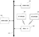
- a display image manipulation system 100 includes an image display device 200, a first terminal device 300, a second terminal device 400, and a wireless router 500. .
- the image display device 200 and the wireless router 500 are connected to the network 510 by wire.
- the image display device 200 is, for example, a large-screen electronic blackboard device that can be drawn by a touch operation.
- the first terminal device 300 and the second terminal device 400 are portable terminal devices.
- the first terminal device 300 is a tablet device having a display screen of about 10 inches, for example.
- the second terminal device 400 is, for example, a smartphone having a display screen that is smaller in size (about several inches) than the tablet device.
- the wireless router 500 is a device for connecting a device capable of wireless communication to a network 510 (including a LAN and the Internet) according to a predetermined communication protocol such as TCP / IP.
- the first terminal device 300 and the second terminal device 400 can access the network 510 via the wireless router 500.
- an image display device 200 includes a control unit (hereinafter referred to as a CPU) 202 that controls the entire image display device 200, a ROM (Read Only Memory) 204 for storing a program, and the like, and volatile A RAM (Random Access Memory) 206, a storage unit 208, and a bus 220.
- the ROM 204 stores programs and data necessary for controlling the operation of the image display apparatus 200.
- the storage unit 208 is a non-volatile storage device that retains data even when power is cut off, and is, for example, a hard disk drive or a flash memory.
- the storage unit 208 may be configured to be detachable.
- the CPU 202, the ROM 204, the RAM 206, and the storage unit 208 are connected to the bus 220. Data (including control information) is exchanged between the units via the bus 220.
- the CPU 202 reads the program from the ROM 204 onto the RAM 206 via the bus 220, and executes the program using a part of the RAM 206 as a work area. That is, the CPU 202 controls each part of the image display device 200 according to a program stored in the ROM 204, and realizes each function of the image display device 200.
- the RAM 206 has a function as a video memory for displaying images. That is, a part of the RAM 206 is used as a VRAM. A configuration including a VRAM in addition to the RAM 206 may be used.
- the image display apparatus 200 further includes a display unit 210, a display control unit 212, an operation unit 214, and a communication IF unit 216.
- the image display device 200 will be described as an electronic blackboard device.
- the display unit 210 is a display panel (liquid crystal panel or the like) for displaying an image.
- the display control unit 212 includes a drive unit for driving the display unit 210, reads out image data stored in the RAM 206 at a predetermined timing, generates a signal for display as an image on the display unit 210, and displays the display data. To the unit 210.
- the image data to be displayed is read from the storage unit 208 by the CPU 202 and transmitted to the RAM 206.
- the communication IF unit 216 is, for example, a NIC (Network Interface Card), and is connected to a hub (not shown) or the like via a communication cable, and is connected to the network 510 via this. As a result, image data is transmitted to and received from a computer or the like connected to the network 510. Image data received from the outside via the communication IF unit 216 is recorded in the storage unit 208.
- NIC Network Interface Card
- the operation unit 214 accepts an input such as an instruction to the image display apparatus 200 by the user.
- the operation unit 214 is arranged on a display unit 210 formed of a liquid crystal panel or the like, and includes a touch detection device having an LED or the like for detecting a touched position, and an operation key unit (both (Not shown).
- a touch detection device having an LED or the like for detecting a touched position
- an operation key unit both (Not shown).
- soft keys are displayed on the display unit 210, and hard keys are arranged on the operation key unit.
- the CPU 202 monitors user operations on these keys. The user can touch these keys to input processing instructions for display contents to the image display apparatus 200. Selection of the soft key displayed on the display unit 210 is performed by detecting a position touched by the touch detection device.
- the touch detection device is, for example, a known infrared cut-off detection type touch panel.
- This touch panel includes a light emitting diode row (hereinafter referred to as an LED row) arranged in a row on two adjacent sides of a rectangular writing surface, and two photodiodes arranged in a row so as to face each LED row.
- a column hereinafter referred to as a PD column. Infrared light is emitted from each LED in the LED row, and each PD in the PD row facing this infrared ray is detected.
- the touched position coordinates can be obtained. Even if the touch detection device is touched with a finger without using the touch pen, the touched position can be similarly detected.
- a touch panel (capacitance method, surface acoustic wave method, resistance film method, or the like) other than the infrared blocking method may be used as the touch detection device.
- the capacitive method the position can be detected without contact as long as it is close to the sensor.
- the image display device 200 displays a screen as shown in FIG.
- the display screen of the display unit 210 is divided into a drawing area 250 and a function button area 240.
- the drawing area 250 is an area where the user can draw by a touch operation. That is, the touched point and the XY coordinates of the movement locus thereof are detected by the touch detection device as described above and transmitted to the CPU 202.
- the CPU 202 writes a predetermined value to the corresponding memory address on the RAM 206 according to the received coordinate data.
- the RAM 206 includes an area for storing drawing data (hereinafter, also referred to as an overlay area) in addition to the area for storing the image data.
- the data of the memory address in which the overlay area is not drawn is set to “0”, and the CPU 202 writes “1” to the memory address corresponding to the drawing position.
- the display control unit 212 superimposes the image data and drawing data (overlay area data) and displays them on the display unit 210. That is, the drawing data is displayed (displays a preset color) at a point where there is drawing data (for example, a pixel in which “1” is recorded in the overlay region), and the point where there is no drawing data (eg, “0” in the overlay region) The image data is displayed in the pixel where “is recorded”. In FIG. 3, a drawn figure 270 is displayed on the image displayed in the drawing area.
- a page operation area 260 is displayed below the drawing area 250.
- a page feed button 262 is a button for sending the displayed page (image data) to the right side and displaying the next page.
- the page return button 264 is a button for sending the displayed page to the left side and displaying the previous page when touched.
- the page number display field 266 displays the number of the currently displayed page among a plurality of pages to be displayed.
- the page operation area 260 has a fixed position and does not move during scrolling. For example, data for displaying the page operation area 260 on the display unit 210 may be stored in an overlay area different from the overlay area for drawing.
- the coordinate data of the touched position is transmitted from the touch detection device to the CPU 202, and the CPU 202 receives the received coordinate data at the position in the area where the page feed button 262 is displayed. Judge that there is. Then, the CPU 202 transmits image data of the next page to the RAM 206 and transmits a page feed command to the display control unit 212. In response to this, the display control unit 212 generates a signal for displaying an image in the middle of page feed from the image data corresponding to the currently displayed page on the RAM 206 and the image data corresponding to the next page. Generate and output to the display unit 210. As a result, an image in the middle of page turning is displayed on the display unit 210.
- Functions assigned to the function buttons 242 include, for example, a drawing function by a touch operation, an eraser function for deleting drawing of a predetermined area, a function for opening a file (image data) stored in the storage unit 208, and displayed image data Are stored in the storage unit 208, or displayed image data is printed.
- Each function button 242 is displayed as an icon.
- each function button 242 includes an icon that instructs execution of image processing on the displayed image.
- the first terminal device 300 includes a CPU 302 that controls the entire first terminal device 300, a memory 304, a RAM 306, and a bus 320.
- the memory 304 is an electrically rewritable nonvolatile storage device such as a flash memory.
- the memory 304 stores programs and data necessary for controlling the operation of the first terminal device 300.
- the CPU 302, the memory 304, and the RAM 306 are connected to the bus 320. Data (including control information) is exchanged between the units via the bus 320.
- the CPU 302 reads a program from the memory 304 onto the RAM 306 via the bus 320, and executes the program using a part of the RAM 306 as a work area. That is, the CPU 302 controls each part of the first terminal device 300 according to the program stored in the memory 304 and realizes each function of the first terminal device 300.
- the RAM 306 has a function as a video memory for displaying images. That is, a part of the RAM 306 is used as a VRAM. A configuration including a VRAM separately from the RAM 306 may be used.
- the first terminal device 300 further includes a display unit 310, a display control unit 312, an operation unit 314, and a wireless IF unit 316.
- the first terminal device 300 will be described as a tablet device.
- the display unit 310 is a display panel (liquid crystal panel or the like) for displaying an image.
- the display control unit 312 includes a drive unit for driving the display unit 310, reads out image data stored in the RAM 306 at a predetermined timing, generates a signal for display as an image on the display unit 310, and displays the display data. Output to the unit 310.
- the image data to be displayed is read from the memory 304 by the CPU 302 and transmitted to the RAM 306.
- the wireless IF unit 316 performs wireless communication with the wireless router and enables the first terminal device 300 to be connected to the network 510.
- the operation unit 314 accepts an input such as an instruction to the first terminal device 300 by the user.
- the operation unit 314 is arranged on a display unit 310 configured with a liquid crystal panel or the like, and includes a touch panel for detecting a touched position and an operation key unit (none of which are shown). Yes.
- a soft key is displayed on the display unit 310, and a hard key is arranged on the operation key unit.
- the CPU 302 monitors user operations on these keys. The user can input instructions to the first terminal device 300 by touching these keys. Selection of the soft key displayed on the display panel is performed by detecting the position touched by the touch panel.
- the touch panel is, for example, a known sheet-like touch panel. Since the detection method of a touch position is well-known, description is not repeated here.
- the CPU 302 of the first terminal device 300 accesses a Web page provided by the image display device 200 by a browser (a software program for displaying a Web page on the Internet), and stores predetermined data. (For example, HTML format data) is received, and an operation screen is generated from the received data and displayed on the display unit 310.
- the CPU 302 detects that the operation unit 314 has been operated by the browser of the Web page, and transmits a request corresponding to the operation to the image display device 200.
- the second terminal device 400 includes a CPU 402, a memory 404, a RAM 406, a display unit 410, a display control unit 412, an operation unit 414, a wireless IF unit 416, and a bus 420.
- the second terminal device 400 has the same configuration as the first terminal device 300 and has the same function. Therefore, only the differences will be described and the same description will not be repeated.
- the second terminal device 400 is different from the first terminal device 300 in that the size of the display unit 410 is smaller than that of the display unit 310, and is smaller and lighter as a whole, and is excellent in portability.
- the size of the display unit 410 is about 4 inches
- the size of the display unit 310 is about 10 inches.
- the CPU 402 of the second terminal device 400 accesses a Web page provided by the image display device 200 by a Web page browser and receives predetermined data (for example, HTML format data). Then, an operation screen is generated from the received data and displayed on the display unit 410. Further, the CPU 402 detects that the operation unit 414 is operated by the browser of the Web page, and transmits a request corresponding to the operation to the image display device 200.
- predetermined data for example, HTML format data
- the image display device 200 is an electronic blackboard device installed in a venue, and this program is executed by touching a predetermined function button arranged in the function button area 240 of the image display device 200.
- the first terminal device 300 is a tablet device having a display screen of about 10 inches
- the second terminal device 400 is a smartphone having a display screen of about 4 inches.
- the image display apparatus 200 can execute an HTTP service that provides a Web page.
- the first terminal device 300 and the second terminal device 400 are devices that can be operated by the presenter, and are assumed to be able to communicate with the wireless router 500 by being turned on. Further, it is assumed that the wireless router 500 is arranged near the image display device 200 (for example, inside a room where a presentation is performed).
- the listener may have a smartphone connected to the network 510.
- the CPU 202 obtains information on a terminal device in the vicinity and connected to the network 510 by wireless communication. Specifically, the CPU 202 broadcasts a predetermined command wirelessly via the wireless router 500, waits for a predetermined time, and receives the response via the wireless router 500.
- the command is a known command such as TCP / IP, and may be a command that is transmitted without designating a transmission destination and returns information on the device itself from each device.
- the broadcast address “255.255.255.255” of TCP / IP is used. Examples of information that can be acquired include the IP address, MAC address, device name (host name), model name, display resolution, and the like of the terminal device.
- IP address of a terminal device can be acquired, additional information such as a device name (host name) or a model name can be obtained by using a command (such as ping or nslookup) that further transmits information to the IP address. You may get it.
- a command such as ping or nslookup
- the CPU 202 selects portable terminal devices from the information acquired in step 600 and displays information that can identify them on the display unit 210. For example, as shown in FIG. 7, the CPU 202 displays a list of model names and IP addresses, and displays a screen 272 for selecting from the list.
- information (model name and IP address) is displayed. The user can select the first terminal device 300 and the second terminal device 400 from the list if information for specifying the first terminal device 300 and the second terminal device 400 is known in advance. Even if it is not known in advance, each terminal device can be operated to display corresponding information on the display unit of each terminal device.
- the first terminal device 300 and the second terminal device 400 can be selected from the list.
- an IP address is automatically assigned to a terminal device capable of wireless communication by a function such as DHCP of the wireless router 500
- each terminal device is operated in the same manner, and information corresponding to the display unit of each terminal device is displayed. Display it.
- the selection screen 272 displays that two types of tablet devices and smartphones can be selected.
- the line is highlighted to indicate that the line has been selected. Up to two lines are displayed in reverse video, and when the third line is selected, the reverse display of the line selected and inverted first is restored. Accordingly, up to two units can be selected.
- step 604 the CPU 202 determines whether or not the selection of the terminal device to be used is completed from the selection screen 272 displayed on the display unit 210. For example, if the determination key 274 illustrated in FIG. 7 is touched and the selected terminal device satisfies a predetermined condition, the CPU 202 determines that the selection of the terminal device to be used has been completed. If it is determined that the selection is complete, control proceeds to step 606. Otherwise, step 604 is repeated. When the control proceeds to step 606, the CPU 202 deletes the selection screen 272.
- the predetermined condition is stored in the storage unit 208 in advance.
- the model name of the usable terminal device and the screen size (in inches) are associated with each other and stored in the storage unit 208 as a table. If the model name selected on the selection screen 272 is not in the table, the CPU 202 determines that no usable terminal device has been selected.
- the CPU 202 determines that a usable terminal device is selected if the model name selected on the selection screen 272 is in the table.
- the CPU 202 obtains the screen sizes of the two selected terminal devices from the table, and determines that the selection is completed only when the screen sizes are different types. To do. Otherwise, the CPU 202 determines that the selection has not been completed, and displays, for example, on the display unit 210 that a terminal device with a different screen size should be selected.
- the screen size is classified into two types depending on, for example, whether or not it is a predetermined threshold value or more.
- the threshold value is, for example, 7 inches.
- the display contents of the image display device can be easily operated and efficient presentation can be performed.
- the screen size is not determined.
- the first terminal device (tablet device) 300 and the second terminal device (smartphone) 400 are selected, it is determined that the selection is completed.
- the CPU 202 permits access to the terminal device selected in step 604, and stores information on the terminal device in the RAM 206.
- the CPU 202 stores information on the selected one or two IP addresses and screen size (number of inches) in association with each other.
- the CPU 202 displays a predetermined URI (Uniform Resource Identifier) that can provide a predetermined Web page (an operation screen page to be described later) by the executing HTTP service on the display unit 210.
- URI Uniform Resource Identifier
- step 608 the CPU 202 determines whether or not there is an access from the terminal device permitted in the access in step 606. Specifically, the CPU 202 receives a request to access a predetermined URI, and determines whether the IP address included in the request matches the IP address stored in the RAM 206 in step 606. If it is determined that they match, the control proceeds to step 610. Otherwise, step 608 is repeated. If they match, the CPU 202 sets a flag corresponding to the received IP address among the IP addresses stored in the RAM 206 (information indicating the presence / absence of access from the terminal device permitted to access) to “1” (initial value is set). “0”).
- the CPU 202 determines whether or not the terminal device that has requested access is the tablet device (first terminal device 300).
- the tablet device means a terminal device having a screen size of 7 inches or more, for example. Therefore, specifically, the CPU 202 determines whether or not it is a tablet device by determining whether or not the value of the screen size stored in the RAM 206 corresponding to the IP address is “7” or more. . If it is determined that the device is a tablet device, control proceeds to step 612. Otherwise, control passes to step 618.
- step 612 the CPU 202 determines whether or not two types of terminal devices are selected in step 604. Specifically, the CPU 202 determines whether there are two IP addresses stored in the RAM 206 in step 606. If it is determined that two types of terminal devices have been selected, control proceeds to step 614. Otherwise, control passes to step 616.
- the CPU 202 transmits the first data to the terminal device accessed in step 608.
- the first data is data in a format that can be displayed by the browser of the terminal device (for example, HTML format data), and generates a screen suitable for the display unit (7 inches or more, typically about 10 inches) of the tablet device. It is data to do.
- a suitable screen means a screen whose size and arrangement are determined so that displayed images, icons, characters, and the like are easily visible to humans and are easily operated. To do.
- the CPU 202 transmits the second data to the terminal device accessed in step 608.
- the second data is data in a format that can be displayed by the browser of the terminal device, and is data for generating a screen suitable for the display unit of the tablet device. However, the second data is data for generating a screen different from the screen generated by the first data.
- the CPU 202 transmits the third data to the terminal device accessed in step 608.
- the third data is data in a format that can be displayed by the browser of the terminal device, and is data for generating a screen suitable for the display unit of a smartphone display unit (less than 7 inches, typically about 4 inches). is there.
- the first to third data are all data for generating a screen including an icon for an operation on the display content of the image display device 200 (hereinafter referred to as an operation icon).
- the operation icons included in the respective screens generated from the first data and the third data are complementary. That is, the operation icon generated based on the first data and displayed on the tablet device (first terminal device 300) is different from the operation icon generated based on the third data and displayed on the smartphone.
- the operation icons included in the respective screens generated from the second data and the third data are not complementary. The same operation is used for the operation icon generated based on the second data and displayed on the tablet device (first terminal device 300) and the operation icon generated based on the third data and displayed on the smartphone. An icon for it is included.
- the operation icon displayed by the third data may be completely included in the operation icon displayed by the second data.
- step 620 the CPU 202 determines whether or not data transmission to all the terminal devices permitted in step 606 has been completed. If it is determined that the process has been completed, control proceeds to step 622. Otherwise, control returns to step 608. In step 606, there are cases where two terminal devices are permitted. In this case, it is determined that data transmission has been completed to the two terminal devices. Specifically, if all the flag values stored in the RAM 206 are “1”, the CPU 202 determines that the process has been completed, and otherwise determines that the process has not been completed.
- step 608 to step 620 data corresponding to the permitted number is transmitted to the terminal device permitted in step 606.
- step 604 data for generating a screen including a complementary operation icon suitable for each terminal device is transmitted.
- step 604 data for generating a screen including an operation icon suitable for the terminal device is transmitted.
- an operation screen including an operation icon is displayed from the received data by the browser on the terminal device that has received the data.
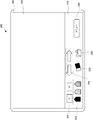
- the selected tablet device is generated based on the received second data as shown in FIG. A screen is displayed.
- the display screen 330 of the display unit 310 of the tablet device (first terminal device 300) is divided into an image area 340 and an operation area 350.
- the image area 340 the same image as that displayed on the display unit 210 of the image display device 200 at the time of presentation is displayed.
- the operation area 350 which is a user interface, an operation icon for the image display device 200, particularly an operation icon for the image displayed on the display unit 210 of the image display device 200 is displayed.
- an enlargement / reduction icon 352 an icon for designating a color of a drawing pen (hereinafter referred to as a pen color designation icon) 354, a left-right scroll icon 356, and a drawn line are erased.
- An eraser icon 358 is displayed.
- a file open icon 362 for opening a file to be displayed on the display unit 210 of the image display device 200 is displayed as an operation icon for the image display device 200.
- the menu icon 360 is touched, other operation icons not displayed in FIG. 8 are displayed.
- a screen generated based on the received third data is displayed on the selected smartphone (second terminal device 400) as shown in FIG.
- the An operation icon for the image displayed on the display unit 210 of the image display device 200 is displayed on the display screen 430 of the display unit 410 of the smartphone (second terminal device 400). Specifically, an enlargement / reduction icon 452 and a left-right scroll icon 456 are displayed. These icons constitute a user interface.
- the smartphone (second terminal device 400) in FIG. 9 includes a hardware back key 462, a trackball 464, and a home key 468 in the operation unit 460. Since these hardware keys may not be equipped depending on the model of the smartphone, they are not used for operations on the image display device 200.
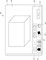
- the selected tablet device (first terminal device 300) receives the first received as shown in FIG. A screen generated based on one data is displayed. The same screen as FIG. 9 is displayed on the selected smartphone (second terminal device 400).
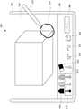
- the display screen 330 of the display unit 310 of the tablet device (first terminal device 300) shown in FIG. 10 is divided into an image area 340 and an operation area 350, as in FIG. In the image area 340, the same image as that displayed on the display unit 210 of the image display device 200 at the time of presentation is displayed.
- an operation icon for the image display device 200 is displayed.
- operation icons a pen color designation icon 354, an eraser icon 358, and a file open icon 362, which are the same icons as in FIG. 8, are displayed.
- an icon 370 for specifying the width of the line drawn by the pen of each color an icon 372 for specifying the width of the eraser, the operation performed immediately before is canceled, and the original state
- An undo icon 374 for returning to the screen and a redo icon 376 for executing the canceled operation again are displayed.
- the enlargement / reduction icon 352 and the left-right scroll icon 356 are not displayed.
- the smartphone icon (second terminal device 400) used simultaneously with the tablet device (first terminal device 300) can be enlarged and operated as an operation icon that can execute the same operation. This is because the reduction icon 452 and the left / right scroll icon 456 are displayed.
- the tablet device (first terminal device) and the smartphone (second terminal device 400) are selected, the tablet device (first terminal device) is not displayed on the tablet device by not displaying the same icon as the operation icon displayed on the smartphone.
- the operation area 350 of the terminal device 300) can be used effectively, and further operation icons can be displayed as described above.
- step 622 the CPU 202 determines whether or not an operation for the image display device 200 has been received. If it is determined that an operation has been received, control proceeds to step 624. Otherwise, step 622 is repeated.
- step 624 CPU 202 determines whether or not the received operation is an instruction to end.
- the termination instruction is, for example, that the image display apparatus 200 is turned off. If it is determined that an end instruction has been received, the program ends. Otherwise, control passes to step 626.
- step 626 the CPU 202 executes processing corresponding to the received operation. Thereafter, control returns to step 622.
- the presenter can operate the selected terminal device and perform the presentation easily and effectively.
- a screen as shown in FIG. 10 is displayed on the tablet device,
- the selected file is read from the storage unit 208 of the image display device 200 and displayed on the display unit 210 of the image display device 200. If multiple page images are included, the first image is displayed.
- the presenter can operate the displayed image by touching the operation icon arranged in the operation area 350 or by touching the image area 340.
- the presenter selects a color to be drawn by touching the pen color designation icon 354 and then drags the pen tip while touching the image area 340 using the touch pen 332, as shown in FIG.
- a figure 270 can be drawn on the screen.
- the same graphic 270 is drawn on the screen of the display unit of the image display device as shown in FIG. Since a screen as shown in FIG. 9 is displayed on the smartphone (second terminal device 400), enlargement / reduction of the image displayed on the display unit 210 of the image display device 200, or left-right scrolling is performed on the smartphone. Can be operated.
- a screen as shown in FIG. 8 is displayed on the tablet device, and the inventor selects a file to be used in the same manner as above, An image is displayed on the display unit 210 of the image display device 200.
- the same image as the image displayed on the display unit 210 of the image display device 200 is displayed on the tablet device in the image region 340.
- the presenter can perform drawing similarly to FIG.
- an enlargement / reduction icon 352 and a left / right scroll icon 356 are also displayed, and these operations can be executed by one tablet device (first terminal device 300).
- the presenter selects only the smartphone (second terminal device 400), the screen as shown in FIG. 9 is displayed on the martphone, so the presenter can display the display unit 210 of the image display device 200.
- the displayed image can be enlarged / reduced and left / right scrolled by operating the smartphone.
- the presenter selects a terminal device capable of wireless communication to be used before the presentation is performed, and operates the image display device 200 using the selected terminal device, particularly the display unit 210 of the image display device 200. Operations on the displayed image can be performed.
- the presenter selects one terminal device, an operation screen suitable for the size of the display screen of the terminal device is displayed on the terminal device. Therefore, the presenter can easily and efficiently make a presentation while facing the audience.
- a screen that includes operation icons in a complementary manner is displayed on the screen of each terminal device. Therefore, the presenter can use more operation icons, and can make presentation more easily and efficiently while facing the audience.
- the present invention is not limited to this.
- an operation for enlarging a part of an image displayed on the display unit 210 of the image display device 200 (hereinafter referred to as a pan operation) may be possible.
- the display screen 430 is divided into an image area 440 and an operation area 450.
- an enlargement / reduction icon 452 and a left-right scroll icon 456 are displayed.
- a pan area 444 can be designated on the image area 440.
- the pan area 444 can be specified by touching two points on the image area 440, for example. Since a rectangle having the two touched points as the upper left and lower right vertices can be determined, the rectangle may be drawn in the image region 440 as a pan region 444.
- the pan area 444 is determined, an image of a portion corresponding to the pan area 444 is enlarged and displayed on the display unit 210 of the image display device 200. If two terminal devices are selected, it is preferable to display a corresponding enlarged image on the tablet device as shown in FIG.
- the presenter can more easily draw on the image displayed on the tablet device (writing characters, etc.) than when the image is displayed on the full screen. it can. Only the display image of the tablet device may be enlarged and displayed without enlarging the display image of the image display device 200.
- the document is appropriately scanned and displayed on the display unit 210 of the image display device 200, or the displayed screen can be printed.
- an image forming apparatus 520 that is a multifunction device capable of printing and reading a document (hereinafter also referred to as scanning) may be connected to a network 510.
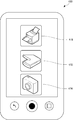
- predetermined data is transmitted from the image display device 200 to the smartphone (second terminal device 400) to display icons as shown in FIG.
- the icon shown in FIG. 17 is displayed on a part of the screen shown in FIG. 9 or FIG.
- the smartphone (second terminal device 400) This can be realized by transmitting a command to the image display device 200 and transmitting predetermined data from the image display device 200 to the smartphone (second terminal device 400) in response thereto.
- the smartphone (second terminal device 400) generates the screen of FIG. 17 from the received data.
- the print icon 470 is an icon for causing the image forming apparatus 520 to execute printing.
- a print instruction is transmitted from the smartphone (second terminal device 400) to the image display device 200 via the wireless router 500.
- the image display device 200 Upon receiving the instruction, the image display device 200 generates image data for printing and transmits it as a print job to the image forming device 520 (the image display device 200 has information on the IP address of the image forming device 520). And).
- data of a screen (including drawing information) currently displayed on the display unit 210 of the image display apparatus 200 is transmitted from the image display apparatus 200 to the image forming apparatus 520 and printed by the image forming apparatus 520.
- the information drawn at the time of presentation can be printed, and a plurality of copies can be copied and distributed to the audience.
- the scan icon 472 is an icon for scanning a document set on the image forming apparatus 520.
- a scan instruction is transmitted from the smartphone (second terminal device 400) to the image display device 200 via the wireless router 500.
- the image display apparatus 200 that has received the instruction transmits a scan instruction to the image forming apparatus 520.
- the image forming apparatus 520 scans the document and transmits the generated image data to the image display apparatus 200.
- the image display device 200 displays the received image data on the display unit 210. This makes it possible to display and discuss new information as appropriate during the presentation.
- the scan instruction may be transmitted directly from the smartphone (second terminal apparatus 400) to the image forming apparatus 520. Also in this case, the generated image data is transmitted to the image display device 200.
- the data capture icon 474 is an icon for transmitting image data stored in the memory 404, such as image data captured by the camera of the smartphone (second terminal device 400), to the image display device 200.
- image data stored in the memory 404 such as image data captured by the camera of the smartphone (second terminal device 400)
- the data capture icon 474 is touched, for example, a list of image data stored in the memory 404 is displayed on the display unit 410.
- the file is transmitted to the image display device 200 (for example, FTP transmission).
- the image display device 200 stores the received data in the storage unit 208 and displays the data on the display unit 210 as appropriate.
- step 618 the smartphone (second terminal device 400) differs depending on whether the smartphone (second terminal device 400) is selected alone or together with the tablet device (first terminal device 300). Data may be sent.
- the processing of the step assigned with the same number as in FIG. 6 is as described above, and therefore, repeated description will not be repeated.
- FIG. 18 differs from FIG. 16 in that step 700 and step 702 are included.
- the CPU 202 determines whether or not two types of terminal devices are selected in step 604. Determine. Specifically, the CPU 202 determines whether there are two IP addresses stored in the RAM 206 in step 606. If it is determined that two types of terminal devices are selected, control proceeds to step 618. Otherwise, control passes to step 702.
- the CPU 202 transmits the fourth data to the terminal device accessed in step 608.
- the fourth data is data in a format that can be displayed by the browser of the terminal device, and is data for generating a screen suitable for the display unit of the smartphone.
- the fourth data is data for generating a screen different from the screen generated by the third data. That is, when a smartphone is selected, different operation screens are displayed on the smartphone depending on whether or not the smartphone is selected. For example, when a smartphone is selected alone, a screen capable of panning shown in FIG. 14 is displayed, and when a smartphone is selected together with the tablet, the operation screen shown in FIG. 9 can be displayed. . For example, when a smartphone is selected together with the tablet device and the operation screen of the smartphone is as shown in FIG. 9, the pan operation may be performed on the screen displayed on the tablet device.
- the CPU 202 transmits the third data from the second terminal apparatus 400 before transmitting the third data.
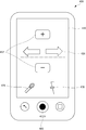
- Information indicating whether or not the voice communication function is provided is acquired. If the second terminal device 400 has a voice communication function, the CPU 202 transmits, to the second terminal device 400, data indicating icons constituting a user interface as shown in FIG. .
- the third data is processed by the browser of the second terminal device 400, and a screen as shown in FIG. 19 is displayed. If the second terminal device 400 does not have a voice communication function, the CPU 202 transmits, to the second terminal device 400, data indicating icons as shown in FIG.
- a microphone icon 476 and a volume adjustment icon 478 are displayed on the display screen 430 in FIG.
- the CPU 402 activates a predetermined program.
- analog audio input from the microphone 480 is sampled to generate digital data, and predetermined audio processing (compression processing, packetization processing, etc.) is performed to generate communication audio data.
- the communication audio data is transmitted from the wireless IF unit 416 to the image display device 200 via the wireless router 500 and the network 510.
- the CPU 202 of the image display device 200 performs predetermined acoustic processing (packet combining processing, decompression processing, etc.) on the received communication audio data to generate analog audio, and the speaker or venue installed in the image display device 200 Output from the speaker installed in the.
- predetermined acoustic processing packet combining processing, decompression processing, etc.
- the volume control icon 478 can slide the center bar up and down, thereby changing the data representing the volume, changing the signal level of the communication audio data, and changing the volume output from the speaker.
- a known technique may be used.
- Information on whether or not the terminal device has a voice call function may be stored in the storage unit 208 of the image display device 200.
- information (flag) indicating whether or not it has a voice call function is stored in correspondence with the model name of the usable terminal device.
- a model name flag having a voice call function is set to “1”
- a model name flag having no voice call function is set to “0”.
- the CPU 202 determines whether the flag corresponding to the model name of the accessed second terminal device 400 stored in the storage unit 208 is “1” (has a voice function). It is determined whether or not the third data is transmitted.
- the CPU 202 transmits to the second terminal device 400 data indicating icons as shown in FIG. 19 as the third data. If the flag is “0”, the CPU 202 transmits to the second terminal device 400, for example, data indicating an icon as shown in FIG.
- the image display device 200 is operated by voice or the contents inputted by voice can be displayed on the image display device 200.
- the voice call function of the terminal device is used as in the fourth modification.
- a voice recognition icon 482 is displayed in addition to the same icons as in FIG. 19.
- the CPU 402 activates a predetermined program. With this program, communication audio data generated from analog audio input from the microphone 480 is transmitted to the image display device 200 as in the fourth modification.
- the CPU 402 transmits information indicating that the communication voice data to be transmitted is not data to be reproduced as voice but data to be voice-recognized (hereinafter referred to as a voice recognition command). Is transmitted to the image display apparatus 200.
- the CPU 202 of the image display device 200 performs predetermined acoustic processing (packet combining processing, decompression processing, etc.) on the received communication audio data to generate digital audio data. Since the CPU 202 receives the voice recognition command, the CPU 202 recognizes the digital voice data and generates text data.
- the generated text data is a character code (JIS code, shift JIS code, etc.) string corresponding to the content of the audio data.
- JIS code Japanese Industrial Standardization Standardization
- the generated character code string is used for the operation of the image display apparatus 200 or for display on the display unit 210 of the image display apparatus 200.
- the CPU 202 stores the generated character code string in the storage unit 208 in advance, and the characters corresponding to the operations of the image display apparatus 200. Compare with the code string, and if there is a matching character code string, the corresponding operation is executed. If there is no matching character code string, an error is displayed on the display unit 210 of the image display device 200.
- the operation to be executed (the operation stored in advance in the storage unit 208) is not limited to the operation of the image display device 200 itself, but may be an operation on the image displayed on the display unit 210.
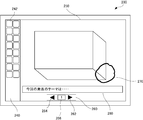
- the CPU 202 When displaying the generated character code string on the image display device 200, the CPU 202 generates image data from the generated character code string and displays it on the display unit 210. For example, as shown in FIG. 21, a character string corresponding to the content of the voice input from the microphone 480 of the second terminal device 400 by the presenter is displayed in the voice recognition result display area 280.
- the image display device 200 When the image display device 200 has a voice operation function and a voice character display function, information for the CPU 202 to determine how to use the generated character code string is the second terminal.
- the device 400 may transmit the audio data before transmitting it. This information is determined, for example, by the CPU 402 displaying a selection screen on the display screen 430 when the voice recognition icon 482 is touched on the second terminal device 400 and the presenter making a selection.
- the voice recognition process may be executed in the second terminal device 400. In that case, from the second terminal device 400, a character code string of a speech recognition result is transmitted to the image display device 200 instead of the speech data.
- the presenter can efficiently make a presentation. Moreover, the presenter can perform an effective presentation by displaying the content of the voice input to the mobile terminal device as characters on the image display device 200.
- the data (first to third data) transmitted from the image display device 200 to the first terminal device 300 and the second terminal device 400 is data for generating a screen including an operation icon (image data).
- the present invention is not limited to this.
- Data for generating a screen on which a text substituting for the operation icon is displayed may be used.
- the data transmitted from the image display device 200 to the first terminal device 300 and the second terminal device 400 is, for example, HTML format data
- an appropriate tag is included in the data so that an icon is not used.
- the area where the text is displayed can be displayed like an operation button.
- a tag ⁇ table> for displaying a table may be used to appropriately specify the shadow thickness of the frame, the thickness of the frame line, the background color of the cell, and the like.
- the communication IF unit 216 of the image display apparatus 200 is a communication apparatus that can be connected to the network 510 via a communication cable.
- the communication IF unit 216 may be the same device as the wireless IF unit 316 of the first terminal device 300, the wireless IF unit 416 of the second terminal device 400, and the like.
- the image display apparatus 200 can access the network 510 via the wireless router 500 by wireless communication, for example.
- the image display device 200 may have a function of the wireless router 500 and be configured to be able to directly communicate with the wireless terminal device.
- the terminal device that can be used by the image display device 200 is searched for by broadcast.
- the present invention is not limited to this.
- a private URI provided by the image display device 200 is accessed using a browser of the terminal device, and used on a screen created based on data transmitted from the image display device 200 to the terminal device.
- You may make it register a terminal device. On the displayed registration screen, it is sufficient to input at least the model name (the IP address is already acquired by the image display device 200 when the URI is accessed), but the display specifications of the terminal device (screen size, resolution, and number of display colors) Etc.) may be entered.
- the same processing as that after step 610 in FIG. 6 may be executed.
- the operation for displaying the result of the operation instructed by the smartphone on the tablet device may be an operation other than the pan operation.
- the present invention is not limited to this.
- the reference value for determination may be a value different from 7 inches.
- the present invention is not limited to this. You may enable the terminal device of three or more types of screen sizes. Even when three or more types of terminal devices are used, it is preferable to display operation icons in a complementary manner on each terminal device. As a result, the presenter considers the difference in portability of a plurality of terminal devices, when explaining while moving for a long time, when explaining while moving for a short time, or when explaining while sitting, etc. Accordingly, a terminal device can be appropriately selected and an efficient presentation can be performed.
- screen display data corresponding to the display specifications of the terminal device may be transmitted.
- the display specifications include, for example, display resolution (1280 ⁇ 800 pixels, 1024 ⁇ 768 pixels, 960 ⁇ 640 pixels, or 800 ⁇ 480 pixels), display color (color or monochrome), and number of display colors (16.77 million colors, Or 260,000 colors). If these pieces of information are also stored in the storage unit 208 in advance corresponding to the model name, the corresponding resolution and the number of display colors can be determined from the model name acquired from the terminal device.
- the image display device 200 may be a projector device or a multi-display device in which a plurality of displays are arranged to form a large screen.
- an image displayed on an image display device can be appropriately remotely controlled using a user interface provided by a mobile terminal device in a presentation or a meeting.
- Display Image Operation System 200 Image Display Device 202 CPU 204 ROM 206 RAM 208 storage unit 210 display unit 212 display control unit 214 operation unit 216 communication IF unit 220 bus 300 first terminal device 400 second terminal device 500 wireless router 510 network 520 image forming apparatus
Landscapes
- Engineering & Computer Science (AREA)
- Theoretical Computer Science (AREA)
- Physics & Mathematics (AREA)
- General Physics & Mathematics (AREA)
- General Engineering & Computer Science (AREA)
- Computer Hardware Design (AREA)
- Multimedia (AREA)
- Signal Processing (AREA)
- Human Computer Interaction (AREA)
- User Interface Of Digital Computer (AREA)
- Controls And Circuits For Display Device (AREA)
- Two-Way Televisions, Distribution Of Moving Picture Or The Like (AREA)
Abstract
操作システム100は、表示パネルを有する携帯端末装置300、400と、画像を表示する表示部、各表示パネルの表示仕様に応じたユーザインターフェイスを生成するためのデータを各携帯端末装置300、400に送信する送信部、及び、表示部に表示された画像に対する処理を実行する処理部を備えた画像表示装置200とを含み、各携帯端末装置300、400は、受信したデータからユーザインターフェイスを生成してユーザに提供し、ユーザによる操作に関する情報を、処理を実行させるための情報として画像表示装置200に送信する。これにより、プレゼンテーション時に発表者は、表示される画像を、携帯端末装置の操作画面のアイコンを用いて適切に遠隔操作することが可能となる。
Description
本発明は、プレゼンテーション等において使用され、画像表示装置に表示される画像に対する操作を行なうシステムに関し、特に、指定した携帯端末装置により遠隔操作可能な、表示画像の操作システム、それを構成する画像表示装置、及びその制御方法に関する。
近年、タッチ描画画像表示装置の1つである、会議等で用いられる電子黒板として、様々な構成のものが実用化されている。特に、大型の表示画面を有する画像表示装置と、タッチパネル等の2次元における位置座標を検知する入力装置とを組合せ、コンピュータシステムとして構成された電子黒板装置が利用されている。大型の電子黒板装置は、プレゼンテーション等にも使用されている。
一般的に、電子黒板装置は、ペン等によって指定される位置座標及び移動量の情報を逐次読取り、読取った情報を元に入力の軌跡を画像表示装置に表示する。これによって、電子黒板装置は手書き入力等の、電子黒板としての動作を実現している。
大型の電子黒板装置を用いて会議又はプレゼンテーションを行なう場合、発表者は、表示内容に対して何らかの操作(文字の書込み等)をするときには、表示画面の方を向いて行なう。これは、聴衆に背中を向けることになり、好ましくない。これを避けるために、別の端末装置を用いて表示内容に対する操作を遠隔操作によって行なうことが考えられる。
遠隔操作に関しては、例えば、特開2000-78302号公報(以下、’302号公報という)に、PHS端末を用いて家電製品、照明装置、及び自動車等を遠隔操作するシステムが開示されている。このシステムでは、PHS端末が、各種電気製品に装備された送受信制御装置と無線通信し、各電気製品側から送信された操作メニューをPHS端末の画面に表示する。ユーザは、PHS端末の表示メニューを操作して電気製品を遠隔操作する。
また、特開2002-247539号公報(以下、’539号公報という)には、インターネット経由で取得した電子データを表示できるネットワークプロジェクタ装置を、インターネット経由で遠隔操作する技術が開示されている。このプロジェクタ装置はWebページを提供するWebサーバを備えており、このプロジェクタ装置を操作するための操作画面データを操作用情報機器に送信する。ユーザは、操作用情報機器のWebブラウザによって表示される画面上で操作することによって、プロジェクタ装置を遠隔操作する。
しかし、’302号公報に開示されたシステムでは、遠隔操作装置であるPHSの表示画面が小さいので、可能な操作が限定され、操作が難しい問題がある。近年普及しているスマートフォン等は表示解像度が向上しているが、表示画面が小さいので、同様の問題がある。また、’302号公報及び’539号公報によっては、プレゼンテーション画面に直接書込みを行なうことができない問題がある。
さらに、実際のプレゼンテーション又は会議等においては、発表者が着座して説明する場合、演壇上を移動しながら説明する場合、又は表示画面の近くまで行って説明する場合等、発表形式には種々のタイプがある。1つのプレゼンテーション中に、着座と移動とを頻繁に繰返す発表者もいる。’302号公報及び’539号公報に開示された技術は、これらに適切に対応することもできない。
これは、電子黒板装置に限らず、プロジェクタ装置、又はマルチディスプレイ装置等の大型の画像表示装置を用いてプレゼンテーション又は会議等を行なう場合に共通して生じる問題である。
したがって、本発明は、プレゼンテーション等で使用され、画像表示装置に表示される画像を、発表者の発表形式等に応じて適切に携帯端末装置で遠隔操作することが可能な、表示画像の操作システム、それを構成する画像表示装置、及びその制御方法を提供することを目的とする。
上記の目的は、下記によって達成することができる。
本発明の第1の局面に係る画像表示装置は、画像を表示する表示部と、画像を表示する表示パネルを有する携帯端末装置の表示パネルの表示仕様に応じたユーザインターフェイスを生成するためのデータを、携帯端末装置に送信する送信部と、表示部に表示された画像に対する処理を実行する処理部と、処理部に処理を実行させるための情報を携帯端末装置から受信する受信部とを備える。処理を実行させるための情報は、データが携帯端末装置によって処理されることによってユーザに提供されるユーザインターフェイスを介したユーザの操作に関する情報である。
好ましくは、ユーザインターフェイスを生成するためのデータは、携帯端末装置によって処理されることによって、部分画像を含む、表示パネルに表示される画面が生成されるデータであり、送信部は、複数の携帯端末装置の各々に、各々の表示仕様に応じたユーザインターフェイスを生成するためのデータを送信し、処理部は、複数の携帯端末装置の各々の表示パネルに表示される画面に含まれる部分画像が選択されたことを表す情報に応じて、選択された当該部分画像に対応する処理を、表示部に表示された画像に対して実行する。
より好ましくは、複数の携帯端末装置の各々の表示パネルに表示される画面は、相互に異なる部分画像を含む。
さらに好ましくは、表示仕様は、携帯端末装置の表示画面の大きさ、表示解像度、及び表示色数のうちの何れかである。
本発明の第2の局面に係る表示画像の操作システムは、画像を表示する表示パネルを有する携帯端末装置と、画像を表示する表示部、携帯端末装置の表示パネルの表示仕様に応じたユーザインターフェイスを生成するためのデータを携帯端末装置に送信する送信部、表示部に表示された画像に対する処理を実行する処理部、及び、処理部に処理を実行させるための情報を携帯端末装置から受信する受信部を備えた画像表示装置とを含む。携帯端末装置は、受信したデータからユーザインターフェイスを生成して、ユーザに提供し、ユーザインターフェイスを介した当該ユーザの操作に関する情報を、処理を実行させるための情報として、受信部に送信する。
本発明の第3の局面に係る制御方法は、画像を表示する表示部と、データの送受信部と、表示部に表示された画像に対する処理を実行する処理部とを備えた画像表示装置の制御方法であって、画像を表示する表示パネルを有する携帯端末装置から、送受信部により、表示パネルの表示仕様に関する情報を取得するステップと、取得した表示仕様に関する情報に応じたユーザインターフェイスを生成するためのデータを、送受信部により、携帯端末装置に送信するステップと、表示部に画像を表示するステップと、携帯端末装置によってデータから生成されるユーザインターフェイスを介したユーザの操作に関する情報を、携帯端末装置から送受信部により取得するステップと、ユーザの操作に関する情報に対応する処理を、表示部に表示された画像に対して、処理部により実行するステップとを含む。
本発明によれば、プレゼンテーション又は会議等において、画像表示装置に表示される画像を、携帯端末装置によって提供されるユーザインターフェイスを用いて適切に遠隔操作することが可能となる。
また、予め端末装置に操作用のアプリケーションをインストールする必要がない。したがって、そのような手間を省くことができ、個人所有の携帯端末装置を速やかに利用することができ、アプリケーションをインストールするための記憶領域を端末装置に確保する必要もない。
操作に使用される複数台の携帯端末装置の各々に、表示仕様(携帯端末装置の表示画面の大きさ、表示解像度、及び表示色数等)に応じて、異なる部分画像(操作用アイコン)を含む操作画面を表示することによって、発表者が適宜端末装置を選択して、効率的に発表を行なうことができる。例えば、操作に使用する携帯端末装置の1台を、主催者が用意したタブレット装置とし、これに加えて発表者が所有するスマートフォンを使用可能にすることによって、発表者は使い慣れたスマートフォンを用いて容易に操作を行なうことができる。
また、2台の携帯端末装置の一方の携帯端末装置で指示した操作の結果を、画像表示装置に表示するとともに、他方の携帯端末装置にも表示することにより、他方の携帯端末装置上での操作が容易になる。
また、使用可能な携帯端末装置を自動的に検索することによって、操作に使用する携帯端末装置の指定を容易に行なうことができる。
以下の実施の形態では、同一の部品には同一の参照番号を付してある。それらの名称及び機能も同一である。したがって、それらについての詳細な説明は繰返さない。
図1を参照して、本発明の実施の形態に係る表示画像の操作システム100は、画像表示装置200、第1端末装置300、第2端末装置400、及び無線ルータ500を備えて構成される。画像表示装置200及び無線ルータ500は、有線でネットワーク510に接続されている。画像表示装置200は、例えば、タッチ操作によって描画可能な大画面の電子黒板装置である。第1端末装置300及び第2端末装置400は携帯端末装置である。第1端末装置300は、例えば10インチ程度の表示画面を有するタブレット装置である。第2端末装置400は、例えば、タブレット装置よりもサイズの小さい(数インチ程度)表示画面を有するスマートフォンである。無線ルータ500は、TCP/IP等の所定の通信プロトコルにしたがって、無線通信可能な機器をネットワーク510(LAN及びインターネットを含む)に接続するための装置である。第1端末装置300及び第2端末装置400は、無線ルータ500を介してネットワーク510にアクセスすることができる。
図1には示していないが、表示画像の操作システム100の周囲には、第1端末装置300及び第2端末装置400以外の無線通信可能な端末装置が存在している場合がある。
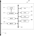
図2を参照して、画像表示装置200は、画像表示装置200全体を制御する制御部(以下、CPUという)202と、プログラム等を記憶するためのROM(Read Only Memory)204と、揮発性の記憶装置であるRAM(Random Access Memory)206と、記憶部208と、バス220とを備えている。ROM204には、画像表示装置200の動作を制御するのに必要なプログラム及びデータが記憶されている。記憶部208は、通電が遮断された場合にもデータを保持する不揮発性の記憶装置であり、例えば、ハードディスクドライブ、又はフラッシュメモリ等である。記憶部208は着脱可能に構成されていてもよい。
CPU202、ROM204、RAM206、及び記憶部208はバス220に接続されている。各部間のデータ(制御情報を含む)交換は、バス220を介して行なわれる。CPU202は、バス220を介してROM204からプログラムをRAM206上に読出して、RAM206の一部を作業領域としてプログラムを実行する。即ち、CPU202は、ROM204に格納されているプログラムにしたがって画像表示装置200を構成する各部の制御を行ない、画像表示装置200の各機能を実現する。
RAM206は、画像を表示するためのビデオメモリとしての機能を備えている。即ち、RAM206の一部はVRAMとして使用される。RAM206とは別にVRAMを備える構成であってもよい。
画像表示装置200はさらに、表示部210、表示制御部212、操作部214、及び通信IF部216を備えている。ここでは、画像表示装置200は電子黒板装置であるとして説明する。
表示部210は、画像を表示するための表示パネル(液晶パネル等)である。表示制御部212は、表示部210を駆動するための駆動部を備え、RAM206に記憶された画像データを所定のタイミングで読出し、表示部210に画像として表示するための信号を生成して、表示部210に出力する。表示される画像データは、CPU202が記憶部208から読出して、RAM206に伝送する。
通信IF部216は、例えばNIC(Network Interface Card)であり、通信ケーブルでハブ(図示せず)等に接続され、これを介してネットワーク510に接続される。これによって、ネットワーク510に接続されたコンピュータ等との間で画像データを送受信する。通信IF部216を介して外部から受信した画像データは、記憶部208に記録される。
操作部214は、ユーザによる画像表示装置200に対する指示等の入力を受付ける。電子黒板装置では、操作部214は、液晶パネル等で構成された表示部210の上に配置され、タッチされた位置を検出するためのLED等を有するタッチ検出装置、及び操作キー部(何れも図示せず)を備えている。画像表示装置200を操作するために、表示部210にはソフトキーが表示され、操作キー部にはハードキーが配置される。CPU202は、これらのキーに対するユーザの操作を監視する。ユーザはこれらのキーにタッチして、画像表示装置200に対して、表示内容に対する処理の指示を入力することができる。表示部210に表示されたソフトキーの選択は、タッチ検出装置によってタッチされた位置を検出することによって行なわれる。
タッチ検出装置は、例えば公知の赤外線遮断検出方式のタッチパネルである。このタッチパネルは、長方形の書込面の隣接する2辺にそれぞれ一列に配置された発光ダイオード列(以下、LED列という)と、それぞれのLED列に対向させて一列に配置された2つのフォトダイオード列(以下、PD列という)とを備えている。LED列の各LEDから赤外線を発光し、この赤外線を対向するPD列の各PDが検出する。
ユーザがタッチペンでタッチパネル上の1点にタッチすると、タッチペンのペン先によって赤外線が遮断される。したがって、タッチされた位置座標を求めることができる。タッチペンを使用せずに、指でタッチ検出装置にタッチしても、同様にタッチされた位置を検出することができる。
タッチされた位置の検出技術は公知であるので、これ以上の説明は繰返さない。また、タッチ検出装置には、赤外線遮断方式以外のタッチパネル(静電容量方式、表面弾性波方式、又は抵抗膜方式等)を用いてもよい。静電容量方式では、センサに近接していれば非接触でも位置を検出することができる。
画像表示装置200には、図3に示すような画面が表示される。表示部210の表示画面は、描画領域250と機能ボタン領域240とに区分されている。描画領域250は、ユーザがタッチ操作によって描画できる領域である。即ち、タッチされた点及びその移動軌跡のXY座標が、上記したようにタッチ検出装置によって検出され、CPU202に伝送される。CPU202は、受信した座標データに応じて、RAM206上の対応するメモリアドレスに所定値を書込む。RAM206上の画像データの画素値を変更してもよいが、ここでは、RAM206は、画像データを記憶する領域とは別に、描画データを記憶する領域(以下、オーバレイ領域ともいう)を備えているとする。この場合、例えば、オーバレイ領域の描画されていないメモリアドレスのデータを“0”として、CPU202は、描画位置に対応するメモリアドレスに“1”を書込む。表示制御部212は、画像データと描画データ(オーバレイ領域のデータ)とをスーパーインポーズして表示部210に表示する。即ち、描画データがある点(例えばオーバレイ領域に“1”が記録されている画素)では描画データを表示(予め設定された色を表示)し、描画データがない点(例えばオーバレイ領域に“0”が記録されている画素)では画像データを表示する。図3においては、描画領域に表示された画像の上に、描画された図形270が表示されている。
機能ボタン領域240には、各々特定の機能が割当てられた機能ボタン242が表示される。描画領域250の下部には、ページ操作領域260が表示される。この領域には、ページ送りボタン262、ページ戻しボタン264、及びページ番号表示欄266が表示される。ページ送りボタン262は、タッチされると、表示されているページ(画像データ)を右側に送り、次のページを表示するためのボタンである。ページ戻しボタン264は、タッチされると、表示されているページを左側に送り、前のページを表示するためのボタンである。ページ番号表示欄266には、表示対象の複数のページのうち、現在表示されているページの番号が表示される。ページ操作領域260は、位置が固定されており、スクロール中にも移動しない。例えば、ページ操作領域260を表示部210に表示するためのデータは、描画用のオーバレイ領域とは別のオーバレイ領域に記憶しておけばよい。
ユーザが、ページ送りボタン262をタッチすると、タッチされた位置の座標データがタッチ検出装置からCPU202に伝送され、CPU202は、受信した座標データが、ページ送りボタン262が表示された領域内の位置であると判定する。そして、CPU202は、RAM206に次のページの画像データを伝送し、表示制御部212に、ページ送りのコマンドを伝送する。これを受けて、表示制御部212は、RAM206上の現在表示されているページに対応する画像データと、次ページに対応する画像データとから、ページ送りの途中の画像を表示するための信号を生成し、表示部210に出力する。これによって、表示部210に、ページ送りされている途中の画像が表示される。
機能ボタン242に割当てられる機能は、例えば、タッチ操作による描画機能、所定領域の描画を削除する消しゴム機能、記憶部208に保存されているファイル(画像データ)を開く機能、表示されている画像データを記憶部208に保存する機能、又は表示されている画像データを印刷する機能等である。各機能ボタン242は、アイコンとして表示される。このように、各機能ボタン242は、表示されている画像に対する画像処理の実行を指示するアイコンを含む。
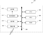
図4を参照して、第1端末装置300は、第1端末装置300全体を制御するCPU302と、メモリ304と、RAM306と、バス320とを備えている。メモリ304は、電気的に書換え可能な不揮発性の記憶装置であり、例えば、フラッシュメモリ等である。メモリ304には、第1端末装置300の動作を制御するのに必要なプログラム及びデータが記憶されている。
CPU302、メモリ304、及びRAM306はバス320に接続されている。各部間のデータ(制御情報を含む)交換は、バス320を介して行なわれる。CPU302は、バス320を介してメモリ304からプログラムをRAM306上に読出して、RAM306の一部を作業領域としてプログラムを実行する。即ち、CPU302は、メモリ304に格納されているプログラムにしたがって第1端末装置300を構成する各部の制御を行ない、第1端末装置300の各機能を実現する。
RAM306は、画像を表示するためのビデオメモリとしての機能を備えている。即ち、RAM306の一部はVRAMとして使用される。RAM306とは別にVRAMを備える構成であってもよい。
第1端末装置300はさらに、表示部310、表示制御部312、操作部314、及び無線IF部316を備えている。ここでは、第1端末装置300はタブレット装置であるとして説明する。
表示部310は、画像を表示するための表示パネル(液晶パネル等)である。表示制御部312は、表示部310を駆動するための駆動部を備え、RAM306に記憶された画像データを所定のタイミングで読出し、表示部310に画像として表示するための信号を生成して、表示部310に出力する。表示される画像データは、CPU302がメモリ304から読出して、RAM306に伝送する。
無線IF部316は、無線ルータとの無線通信を行ない、第1端末装置300をネットワーク510に接続可能にする。
操作部314は、ユーザによる第1端末装置300に対する指示等の入力を受付ける。タブレット装置では、操作部314は、液晶パネル等で構成された表示部310の上に配置され、タッチされた位置を検出するためのタッチパネル、及び操作キー部(何れも図示せず)を備えている。第1端末装置300を操作するために、表示部310にはソフトキーが表示され、操作キー部にはハードキーが配置される。CPU302は、これらのキーに対するユーザの操作を監視する。ユーザはこれらのキーにタッチして、第1端末装置300に対して指示を入力することができる。表示パネルに表示されたソフトキーの選択は、タッチパネルによってタッチされた位置を検出することによって行なわれる。
タッチパネルは、例えば公知のシート状のタッチパネルである。タッチ位置の検出方法は公知であるので、ここでは説明を繰返さない。
このように構成されている第1端末装置300のCPU302は、後述するように、ブラウザ(インターネットのWebページを表示するソフトウェアプログラム)により、画像表示装置200が提供するWebページにアクセスし、所定データ(例えばHTML形式データ)を受信し、受信したデータから操作画面を生成して表示部310に表示する。また、CPU302は、Webページのブラウザにより、操作部314が操作されたことを検出し、操作に応じた要求を画像表示装置200に送信する。
図5を参照して、第2端末装置400は、CPU402、メモリ404、RAM406、表示部410、表示制御部412、操作部414、無線IF部416、及びバス420を備えている。第2端末装置400は、第1端末装置300と同じ構成をしており、同じ機能を有する。したがって、差異のみを説明し、同じ説明を繰返さない。第2端末装置400が第1端末装置300と異なる点は、表示部410の大きさが表示部310よりも小さく、全体としてより小型・軽量であり携帯性に優れている点である。例えば、表示部410の大きさは4インチ程度であり、表示部310の大きさは10インチ程度である。
このように構成されている第2端末装置400のCPU402は、後述するように、Webページのブラウザにより、画像表示装置200が提供するWebページにアクセスし、所定データ(例えばHTML形式データ)を受信し、受信したデータから操作画面を生成して表示部410に表示する。また、CPU402は、Webページのブラウザにより、操作部414が操作されたことを検出し、操作に応じた要求を画像表示装置200に送信する。
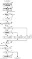
以下に、図6を参照して、図1の表示画像の操作システムを用いてプレゼンテーションを可能にするために画像表示装置200において実行されるプログラムの制御構造に関して説明する。
以下の説明では、画像表示装置200は会場に設置された電子黒板装置であり、本プログラムは、画像表示装置200の機能ボタン領域240に配置された所定の機能ボタンがタッチされることによって実行されるとする。第1端末装置300は約10インチの表示画面を有するタブレット装置であり、第2端末装置400は約4インチの表示画面を有するスマートフォンであるとする。画像表示装置200は、Webページを提供するHTTPサービスを実行可能である。第1端末装置300及び第2端末装置400は発表者が操作可能な装置であり、電源がオンされて無線ルータ500と通信可能になっているとする。また、無線ルータ500は、画像表示装置200の近く(例えば、プレゼンテーションを行なう部屋の内部)に配置されているとする。第1端末装置300及び第2端末装置400以外に、無線ルータ500と無線通信可能な端末装置が存在してもよい。例えば聴講者が、ネットワーク510に接続された状態のスマートフォンを持っていてもよい。
ステップ600において、CPU202は、周辺にある、無線通信でネットワーク510に接続されている端末装置の情報を取得する。具体的には、CPU202は、無線ルータ500を介して所定のコマンドを無線でブロードキャストし、それに対する応答を、所定時間待ち受けて、無線ルータ500を介して受信する。コマンドは、TCP/IP等の公知のコマンドであり、送信先を指定せずに送信され、各機器から機器自体の情報を返信させるコマンドであればよい。ブロードキャストには、例えばTCP/IPのブロードキャストアドレス“255.255.255.255”を使用する。取得可能な情報としては、例えば、端末装置のIPアドレス、MACアドレス、装置名(ホスト名)、機種名、及び表示解像度等がある。例えば、端末装置のIPアドレスを取得できれば、そのIPアドレスに対して、さらに情報を送信させるコマンド(ping、又はnslookup等)を用いて、装置名(ホスト名)、又は機種名等の追加情報を取得してもよい。
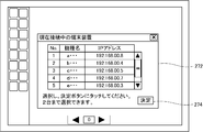
ステップ602において、CPU202は、ステップ600で取得した情報の中から、携帯端末装置を選択し、それらを特定できる情報を表示部210に表示する。CPU202は、例えば図7に示すように、機種名及びIPアドレスをリスト表示し、その中から選択させる画面272を表示する。ここでは、第1端末装置300及び第2端末装置400が無線ルータ500の近くにあり、電源がオンされて無線ルータ500と通信可能になっているので、これらを特定可能な情報(機種名及びIPアドレス)が表示される。ユーザは、第1端末装置300及び第2端末装置400を特定する情報が予め分かっていれば、リストから第1端末装置300及び第2端末装置400を選択可能である。予め分かっていなくても、各端末装置を操作して、各端末装置の表示部に該当する情報を表示させることができる。表示された情報を見れば、リスト中から第1端末装置300及び第2端末装置400を選択可能である。無線ルータ500のDHCP等の機能によって、無線通信可能な端末装置に自動的にIPアドレスが割当てられる場合には、同様に各端装置を操作して、各端末装置の表示部に該当する情報を表示させればよい。選択画面272には、例えば図7に示すように、タブレット装置とスマートフォンの2種類まで選択できる旨を表示する。例えば、リストにタッチされた場合、その行が選択されたこと示すために、その行を反転して表示する。2行までは、反転表示され、さらに3行目が選択された場合には、最初に選択され反転されている行の反転表示を元に戻す。これによって、最大2台まで選択され得る。
ステップ604において、CPU202は、表示部210に表示した選択画面272から使用する端末装置の選択が完了したか否かを判定する。例えば、図7に示した決定キー274がタッチされ、選択されている端末装置が所定条件を満たしていれば、CPU202は、使用する端末装置の選択が完了したと判定する。選択が完了したと判定された場合、制御はステップ606に移行する。そうでなければ、ステップ604が繰返される。制御がステップ606に移行する場合、CPU202は、選択画面272を消去する。
所定条件は、予め記憶部208に記憶されている。例えば、使用可能な端末装置の機種名と画面サイズ(インチ単位)とを対応させてテーブルとして、記憶部208に記憶しておく。CPU202は、選択画面272で選択された機種名がテーブル内になければ、使用可能な端末装置が選択されていないと判定する。
具体的には、1台の端末装置が選択された場合、CPU202は、選択画面272で選択された機種名がテーブル内にあれば、使用可能な端末装置が選択されたと判定する。一方、2台の端末装置が選択された場合、CPU202は、選択された2台の端末装置の画面サイズをテーブルから取得し、異なる種類の画面サイズである場合にのみ、選択が完了したと判定する。そうでなければ、CPU202は、選択が完了していないと判定し、例えば、画面サイズが異なる端末装置を選択すべきである旨を表示部210に表示する。画面サイズは、例えば、所定のしきい値以上であるか否かによって2種類に区分される。しきい値は、例えば7インチである。これは、後述するように、画面サイズの異なる2台の端末装置を使用して、画像表示装置の表示内容を容易に操作し、且つ効率的なプレゼンテーションを可能にするためである。1台だけ選択された場合には、画面サイズは判定されない。第1端末装置(タブレット装置)300及び第2端末装置(スマートフォン)400が選択された場合、選択が完了したと判定される。
ステップ606において、CPU202は、ステップ604で選択された端末装置のアクセスを許可し、端末装置の情報をRAM206に記憶する。例えば、CPU202は、選択された1つ又は2つのIPアドレス及び画面サイズ(インチ数)の情報を対応させて記憶する。このとき、CPU202は、表示部210に、実行しているHTTPサービスによって所定のWebページ(後述する操作画面ページ)を提供可能な所定のURI(Uniform Resource Identifier)を表示する。
ステップ608において、CPU202は、ステップ606でアクセスを許可した端末装置からアクセスがあったか否かを判定する。具体的には、CPU202は、所定のURIへのアクセス要求を受信し、その要求の中に含まれるIPアドレスが、ステップ606でRAM206に記憶したIPアドレスと一致するか否かを判定する。一致したと判定された場合、制御はステップ610に移行する。そうでなければ、ステップ608が繰返される。一致した場合、CPU202は、RAM206に記憶したIPアドレスのうち、受信したIPアドレスに対応するフラグ(アクセス許可した端末装置からのアクセスの有無を表す情報)を“1”にセットする(初期値を“0”とする)。
ステップ610において、CPU202は、アクセス要求があった端末装置がタブレット装置(第1端末装置300)であるか否かを判定する。ここで、タブレット装置とは、例えば画面サイズが7インチ以上である端末装置を意味する。したがって、具体的には、CPU202は、IPアドレスに対応させてRAM206に記憶した画面サイズの値が“7”以上であるか否かを判定することで、タブレット装置であるか否かを判定する。タブレット装置であると判定された場合、制御はステップ612に移行する。そうでなければ、制御はステップ618に移行する。
ステップ612において、CPU202は、ステップ604で2種類の端末装置が選択されているか否かを判定する。具体的には、CPU202は、ステップ606でRAM206に記憶したIPアドレスが2つ存在するか否かを判定する。2種類の端末装置が選択されていると判定された場合、制御はステップ614に移行する。そうでなければ、制御はステップ616に移行する。
ステップ614おいて、CPU202は、ステップ608でアクセスしてきた端末装置に対して第1データを送信する。第1データは、端末装置のブラウザによって表示され得る形式のデータ(例えばHTML形式のデータ)であり、タブレット装置の表示部(7インチ以上。典型的には約10インチ)に適した画面を生成するためのデータである。ここで、適した画面とは、表示される画像、アイコン、及び文字等が人に視認され易く、操作され易い状態で表示されるように、それらのサイズ及び配置が決定されている画面を意味する。
ステップ616おいて、CPU202は、ステップ608でアクセスしてきた端末装置に対して第2データを送信する。第2データは、端末装置のブラウザによって表示され得る形式のデータであり、タブレット装置の表示部に適した画面を生成するためのデータである。但し、第2データは、第1データによって生成される画面と異なる画面を生成するためのデータである。
一方、ステップ610でタブレット装置でないと判定された場合、ステップ618おいて、CPU202は、ステップ608でアクセスしてきた端末装置に対して第3データを送信する。第3データは、端末装置のブラウザによって表示され得る形式のデータであり、スマートフォンの表示部(7インチ未満。典型的には約4インチ)の表示部に適した画面を生成するためのデータである。
第1~第3データは何れも、画像表示装置200の表示内容に対する操作のためのアイコン(以下、操作用アイコンという)を含む画面を生成するためのデータである。後述するように、第1データ及び第3データから生成されるそれぞれの画面に含まれる操作用アイコンは、相補的である。即ち、第1データを基に生成されてタブレット装置(第1端末装置300)に表示される操作用アイコンは、第3データを基に生成されてスマートフォンに表示される操作用アイコンとは異なる。一方、第2データ及び第3データから生成されるそれぞれの画面に含まれる操作用アイコンは、相補的ではない。第2データを基に生成されてタブレット装置(第1端末装置300)に表示される操作用アイコンと、第3データを基に生成されてスマートフォンに表示される操作用アイコンとには、同じ操作用アイコンが含まれている。第3データによって表示される操作用アイコンが、第2データによって表示される操作用アイコンに完全に含まれていてもよい。
ステップ620おいて、CPU202は、ステップ606で許可した全ての端末装置へのデータ送信が完了したか否かを判定する。完了したと判定された場合、制御はステップ622に移行する。そうでなければ、制御はステップ608に戻る。ステップ606では2つの端末装置が許可される場合があるので、その場合には、2つの端末装置にデータ送信すれば完了したと判定される。具体的には、CPU202は、RAM206に記憶したフラグの値が全て“1”であれば、完了したと判定し、そうでなければ完了していないと判定する。
上記のステップ608~ステップ620によって、ステップ606で許可した端末装置に、許可した台数に応じたデータが送信される。ステップ604で2台の端末装置(タブレット装置及びスマートフォン)が選択された場合、それぞれの端末装置に適した、相補的な操作用アイコンが含まれる画面が生成されるデータを送信する。一方、ステップ604で1台の端末装置(タブレット装置又はスマートフォン)が選択された場合、その端末装置に適した操作用アイコンが含まれる画面が生成されるデータを送信する。その結果、データを受信した端末装置には、ブラウザによって、受信したデータから操作用アイコンを含む操作画面が表示される。
例えば、タブレット装置(第1端末装置300)のみが選択された場合、選択されたタブレット装置(第1端末装置300)に、図8に示すように、受信した第2データを基に生成された画面が表示される。タブレット装置(第1端末装置300)の表示部310の表示画面330は、画像領域340と操作領域350とに区分されている。画像領域340には、プレゼンテーション時に画像表示装置200の表示部210に表示される画像と同じ画像が表示される。ユーザインターフェイスである操作領域350には、画像表示装置200に対する操作用アイコン、特に画像表示装置200の表示部210に表示された画像に対する操作用アイコンが表示されている。表示画像に対する操作用アイコンとして、拡大・縮小アイコン352、描画用ペンの色を指定するためのアイコン(以下、ペンの色指定アイコンという)354、左右スクロールアイコン356、描画された線を消すための消しゴムアイコン358が表示されている。表示画像に対する操作用アイコンではないが、画像表示装置200に対する操作用アイコンとして、画像表示装置200の表示部210に表示させるファイルを開くためのファイルオープンアイコン362が表示されている。メニューアイコン360がタッチされた場合、図8に表示されていない他の操作用アイコンが表示される。
スマートフォン(第2端末装置400)のみが選択された場合、選択されたスマートフォン(第2端末装置400)に、図9に示すように、受信した第3データを基に生成された画面が表示される。スマートフォン(第2端末装置400)の表示部410の表示画面430には、画像表示装置200の表示部210に表示された画像に対する操作用アイコンが表示されている。具体的には、拡大・縮小アイコン452、左右スクロールアイコン456が表示されている。これらのアイコンは、ユーザインターフェイスを構成する。図9のスマートフォン(第2端末装置400)は、操作部460に、ハードウェアのバックキー462、トラックボール464、ホームキー468を備えている。これらのハードウェアキーは、スマートフォンの機種によっては装備されていない場合があるので、画像表示装置200に対する操作には使用されない。
一方、タブレット装置(第1端末装置300)及びスマートフォン(第2端末装置400)が選択された場合、選択されたタブレット装置(第1端末装置300)に、図10に示すように、受信した第1データを基に生成された画面が表示される。選択されたスマートフォン(第2端末装置400)には、図9と同じ画面が表示される。図10に示したタブレット装置(第1端末装置300)の表示部310の表示画面330は、図8と同様に、画像領域340と操作領域350とに区分されている。画像領域340には、プレゼンテーション時に画像表示装置200の表示部210に表示される画像と同じ画像が表示される。操作領域350には、画像表示装置200に対する操作用アイコン、特に画像表示装置200の表示部210に表示された画像に対する操作用アイコンが表示されている。操作用アイコンとして、図8と同じアイコンであるペンの色指定アイコン354、消しゴムアイコン358、及び、ファイルオープンアイコン362が表示されている。図10には、これらに加えて、各色のペンによって描画される線の幅を指定するためのアイコン370、消しゴムの幅を指定するためのアイコン372、直前に行なった操作を取消して元の状態に戻すためのアンドゥーアイコン374、取消した操作を再度実行するためのリドゥーアイコン376が表示されている。拡大・縮小アイコン352、及び左右スクロールアイコン356は表示されていない。これは、タブレット装置(第1端末装置300)と同時に使用するスマートフォン(第2端末装置400)には、図9に示したように、同じ操作を実行することができる操作用アイコンとして、拡大・縮小アイコン452、左右スクロールアイコン456が表示されているからである。タブレット装置(第1端末装置300)及びスマートフォン(第2端末装置400)が選択された場合、タブレット装置において、スマートフォンに表示される操作用アイコンと同じアイコンを表示しないことによって、タブレット装置(第1端末装置300)の操作領域350を有効に使用することができ、上記したように、さらなる操作用アイコンを表示できる。
端末装置への所定データの送信が完了した後、ステップ622おいて、CPU202は、画像表示装置200に対する操作を受けたか否かを判定する。操作を受けたと判定された場合、制御はステップ624に移行する。そうでなければ、ステップ622が繰返される。
ステップ624おいて、CPU202は、受けた操作が終了の指示であるか否かを判定する。終了の指示は、例えば、画像表示装置200の電源がOFFされることである。終了の指示を受けたと判定された場合、本プログラムは終了する。そうでなければ、制御はステップ626に移行する。
ステップ626おいて、CPU202は、受けた操作に該当する処理を実行する。その後、制御はステップ622に戻る。
上記のステップ622~ステップ626によって、発表者は選択した端末装置を操作して、プレゼンテーションを容易且つ効果的に行なうことができる。
例えば、発表者が、使用する端末装置としてタブレット装置(第1端末装置300)及びスマートフォン(第2端末装置400)を選択した場合、タブレット装置には図10に示したような画面が表示され、発明者はファイルオープンアイコン362にタッチして、タブレット装置(第1端末装置300)の表示部310(又は画像表示装置200の表示部210)に表示されるリストから、使用したいファイルを選択することができる。これによって、選択されたファイルが画像表示装置200の記憶部208から読出され、画像表示装置200の表示部210に表示される。複数のページ画像が含まれていれば、最初のメージが表示される。同時に、タブレット装置(第1端末装置300)にも、図11に示すように、画像領域340に、画像表示装置200の表示部210に表示される画像と同じ画像が表示される。この状態で、発表者は、操作領域350に配置された操作用アイコンにタッチすることによって、又は画像領域340にタッチすることによって、表示されている画像に対する操作を行なうことができる。例えば、発表者が、ペンの色指定アイコン354にタッチして描画する色を選択した後、タッチペン332を用いて、ペン先を画像領域340にタッチしたままドラッグすることによって、図12に示すように図形270を描画することができる。これによって、図3に示したように、画像表示装置の表示部の画面にも同じ図形270が描画される。スマートフォン(第2端末装置400)には、図9に示したような画面が表示されるので、画像表示装置200の表示部210に表示された画像の拡大・縮小、又は左右スクロールは、スマートフォンを操作して行なうことができる。
発表者がタブレット装置(第1端末装置300)のみを選択した場合、そのタブレット装置には図8に示したような画面が表示され、発明者は上記と同様に使用したいファイルを選択して、画像表示装置200の表示部210に画像を表示させる。同時に、タブレット装置には、図13に示したように、画像領域340に、画像表示装置200の表示部210に表示される画像と同じ画像が表示される。この状態で、発表者は、図12と同様に描画を行なうことができる。図13では、図12と異なり、拡大・縮小アイコン352、及び左右スクロールアイコン356も表示されているので、これらの操作を1台のタブレット装置(第1端末装置300)で実行することができる。
発表者がスマートフォン(第2端末装置400)のみを選択した場合、そのマートフォンには、図9に示したような画面が表示されるので、発表者は、画像表示装置200の表示部210に表示された画像の拡大・縮小、及び左右スクロールを、スマートフォンを操作して行なうことができる。
以上によって、発表者は、プレゼンテーションを実行する前に使用する無線通信可能な端末装置を選択し、選択した端末装置を使用して画像表示装置200に対する操作、特に画像表示装置200の表示部210に表示された画像に対する操作を行なうことができる。発表者が1台の端末装置を選択した場合には、その端末装置の表示画面のサイズに適した操作画面がその端末装置に表示される。したがって、発表者は、聴講者の方を向いたまま、容易且つ効率的にプレゼンテーションを行なうことができる。
発表者が、画面サイズが異なる2台の端末装置を選択した場合には、各端末装置の画面には、操作用アイコンを相補的に含む画面(操作用アイコンが重複しない画面)が表示されるので、発表者は、より多くの操作用アイコンを使用することができ、聴講者の方を向いたまま、より容易、且つより効率的にプレゼンテーションを行なうことができる。
(第1の変形例)
上記では、スマートフォンには、操作用アイコンとして拡大・縮小アイコン452、及び左右スクロールアイコン456が表示される場合を説明したがこれに限定されない。例えば、図14に示すように、画像表示装置200の表示部210に表示されている画像の一部を拡大する操作(以下、パン操作という)が可能であってもよい。図14では、表示画面430は、画像領域440と操作領域450とに区分されている。ユーザインターフェイスである操作領域450には、拡大・縮小アイコン452、左右スクロールアイコン456が表示されている。画像領域440には、プレゼンテーション時に画像表示装置200の表示部210に表示される画像と同じ画像が表示される。画像領域440上ではパン領域444を指定することができる。パン領域444の指定方法は、例えば、画像領域440上の2点にタッチして行なうことができる。タッチされた2点を左上及び右下の頂点とする長方形を決定することができるので、その長方形をパン領域444として、画像領域440に描画すればよい。パン領域444が決定されると、画像表示装置200の表示部210には、パン領域444に対応する部分の画像が拡大表示される。2台の端末装置が選択されていれば、図15に示すようにタブレット装置にも、対応する拡大画像が表示されるようにすることが好ましい。このようにタブレット装置において画像を拡大表示すれば、発表者は、タブレット装置に表示された画像上での描画(文字の書込み等)を、全画面表示されている場合よりも容易に行なうことができる。画像表示装置200の表示画像を拡大せずに、タブレット装置の表示画像のみを拡大表示してもよい。
上記では、スマートフォンには、操作用アイコンとして拡大・縮小アイコン452、及び左右スクロールアイコン456が表示される場合を説明したがこれに限定されない。例えば、図14に示すように、画像表示装置200の表示部210に表示されている画像の一部を拡大する操作(以下、パン操作という)が可能であってもよい。図14では、表示画面430は、画像領域440と操作領域450とに区分されている。ユーザインターフェイスである操作領域450には、拡大・縮小アイコン452、左右スクロールアイコン456が表示されている。画像領域440には、プレゼンテーション時に画像表示装置200の表示部210に表示される画像と同じ画像が表示される。画像領域440上ではパン領域444を指定することができる。パン領域444の指定方法は、例えば、画像領域440上の2点にタッチして行なうことができる。タッチされた2点を左上及び右下の頂点とする長方形を決定することができるので、その長方形をパン領域444として、画像領域440に描画すればよい。パン領域444が決定されると、画像表示装置200の表示部210には、パン領域444に対応する部分の画像が拡大表示される。2台の端末装置が選択されていれば、図15に示すようにタブレット装置にも、対応する拡大画像が表示されるようにすることが好ましい。このようにタブレット装置において画像を拡大表示すれば、発表者は、タブレット装置に表示された画像上での描画(文字の書込み等)を、全画面表示されている場合よりも容易に行なうことができる。画像表示装置200の表示画像を拡大せずに、タブレット装置の表示画像のみを拡大表示してもよい。
(第2の変形例)
プレゼンテーションの状況を考えれば、適宜、原稿をスキャンして画像表示装置200の表示部210に表示する、又は、表示している画面をプリントできることが好ましい。そのためには、例えば、図16に示すように、印刷及び原稿の読込(以下、スキャンともいう)が可能な複合機である画像形成装置520をネットワーク510に接続すればよい。この場合、スマートフォン(第2端末装置400)には、画像表示装置200から所定のデータを送信して、図17に示すようなアイコンを表示する。図17のアイコンの表示は、例えば、図9又は図14に示した画面の一部に、所定のアイコンを表示し、それがタッチされた場合に、スマートフォン(第2端末装置400)が所定のコマンドを画像表示装置200に送信し、それに応答して画像表示装置200からスマートフォン(第2端末装置400)に、所定のデータを送信することで実現できる。スマートフォン(第2端末装置400)は、受信したデータから、図17の画面を生成する。
プレゼンテーションの状況を考えれば、適宜、原稿をスキャンして画像表示装置200の表示部210に表示する、又は、表示している画面をプリントできることが好ましい。そのためには、例えば、図16に示すように、印刷及び原稿の読込(以下、スキャンともいう)が可能な複合機である画像形成装置520をネットワーク510に接続すればよい。この場合、スマートフォン(第2端末装置400)には、画像表示装置200から所定のデータを送信して、図17に示すようなアイコンを表示する。図17のアイコンの表示は、例えば、図9又は図14に示した画面の一部に、所定のアイコンを表示し、それがタッチされた場合に、スマートフォン(第2端末装置400)が所定のコマンドを画像表示装置200に送信し、それに応答して画像表示装置200からスマートフォン(第2端末装置400)に、所定のデータを送信することで実現できる。スマートフォン(第2端末装置400)は、受信したデータから、図17の画面を生成する。
プリントアイコン470は、画像形成装置520に印刷を実行させるためのアイコンである。プリントアイコン470がタッチされた場合、プリント指示が、スマートフォン(第2端末装置400)から無線ルータ500を介して、画像表示装置200に送信される。指示を受信した画像表示装置200は、印刷用の画像データを生成して、画像形成装置520に印刷ジョブとして送信する(画像表示装置200は、画像形成装置520のIPアドレスの情報を持っているとする)。これによって、例えば、画像表示装置200の表示部210に現在表示されている画面(描画情報を含む)のデータが、画像表示装置200から画像形成装置520に送信され、画像形成装置520によってプリントされる。これによって、プレゼンテーション時に描画された情報を印刷し、複数コピーして、聴講者に配布することができる。
スキャンアイコン472は、画像形成装置520にセットされた原稿をスキャンするためのアイコンである。スキャンアイコン472がタッチされた場合、スキャン指示が、スマートフォン(第2端末装置400)から無線ルータ500を介して、画像表示装置200に送信される。指示を受信した画像表示装置200は、画像形成装置520にスキャンの指示を送信する。これを受信した画像形成装置520は、原稿をスキャンして、生成した画像データを画像表示装置200に送信する。画像表示装置200は、受信した画像データを表示部210に表示する。これによって、プレゼンテーション時に、適宜新たな情報を表示して議論することが可能になる。スマートフォン(第2端末装置400)が、画像形成装置520のIPアドレス情報を持っていれば、スマートフォン(第2端末装置400)から直接画像形成装置520にスキャン指示を送信してもよい。その場合にも、生成された画像データは画像表示装置200に送信される。
データ取込アイコン474は、スマートフォン(第2端末装置400)のカメラで撮像した画像データ等の、メモリ404に記憶された画像データを画像表示装置200に送信するためのアイコンである。データ取込アイコン474がタッチされた場合、例えば、メモリ404に記憶されている画像データのリストが表示部410に表示される。表示された中からタッチ操作によってファイルが選択されると、そのファイルが、画像表示装置200に送信される(例えば、FTP送信される)。画像表示装置200は、受信したデータを記憶部208に記憶し、適宜表示部210に表示する。
(第3の変形例)
上記では、スマートフォン(第2端末装置400)が選択された場合、単独で選択されたかタブレット装置(第1端末装置300)と共に選択されたかに依らず、ステップ618において、画像表示装置200からスマートフォン(第2端末装置400)に、同じ画面を生成するための第3データを送信する場合を説明したが、これに限定されない。例えば、図18に示すように、スマートフォン(第2端末装置400)が単独で選択されたかタブレット装置(第1端末装置300)と共に選択されたかに応じて、スマートフォン(第2端末装置400)に異なるデータが送信されてもよい。図18において、図6と同じ番号が付与されたステップの処理は上記で説明した通りであるので、重複説明を繰返さない。
上記では、スマートフォン(第2端末装置400)が選択された場合、単独で選択されたかタブレット装置(第1端末装置300)と共に選択されたかに依らず、ステップ618において、画像表示装置200からスマートフォン(第2端末装置400)に、同じ画面を生成するための第3データを送信する場合を説明したが、これに限定されない。例えば、図18に示すように、スマートフォン(第2端末装置400)が単独で選択されたかタブレット装置(第1端末装置300)と共に選択されたかに応じて、スマートフォン(第2端末装置400)に異なるデータが送信されてもよい。図18において、図6と同じ番号が付与されたステップの処理は上記で説明した通りであるので、重複説明を繰返さない。
図18が図16と異なる点は、ステップ700及びステップ702を含む点である。ステップ610において、アクセス要求があった端末装置がタブレット装置(第1端末装置300)でないと判定された場合、ステップ700において、CPU202は、ステップ604で2種類の端末装置が選択されているか否かを判定する。具体的には、CPU202は、ステップ606でRAM206に記憶したIPアドレスが2つ存在するか否かを判定する。2種類の端末装置が選択されていると判定された場合、制御はステップ618に移行する。そうでなければ、制御はステップ702に移行する。
ステップ702おいて、CPU202は、ステップ608でアクセスしてきた端末装置に対して第4データを送信する。第4データは、端末装置のブラウザによって表示され得る形式のデータであり、スマートフォンの表示部に適した画面を生成するためのデータである。
第4データは、第3データによって生成される画面と異なる画面を生成するためのデータである。即ち、スマートフォンが選択された場合、タブレット装置と共に選択されたか否かによって、スマートフォンに異なる操作画面が表示される。例えば、スマートフォンが単独で選択された場合、図14に示したパン操作が可能な画面が表示され、タブレットと共に選択された場合、図9に示した操作画面が表示されるようにすることができる。例えば、スマートフォンがタブレット装置と共に選択され、スマートフォンの操作画面が図9のようになる場合には、パン操作は、タブレット装置に表示された画面上で実行可能にすればよい。
(第4の変形例)
プレゼンテーション会場が広い場合、発表者がマイクを使用することが多い。スマートフォン等の携帯端末装置は音声通話機能を有するので、この機能を使用できれば便利である。
プレゼンテーション会場が広い場合、発表者がマイクを使用することが多い。スマートフォン等の携帯端末装置は音声通話機能を有するので、この機能を使用できれば便利である。
例えば、図6のステップ602において選択された第2端末装置400が、画像表示装置200にアクセスした場合、ステップ618において、CPU202は、第3データを送信する前に、第2端末装置400から、音声通信機能を有するか否かを表す情報を取得する。第2端末装置400が音声通信機能を有していれば、CPU202は、第3データとして、図19に示すようなユーザインターフェイスを構成するアイコンが表示されるデータを第2端末装置400に送信する。この第3データは第2端末装置400のブラウザによって処理されて、図19のような画面が表示される。第2端末装置400が音声通信機能を有していなければ、CPU202は、第3データとして、例えば図9に示したようなアイコンが表示されるデータを第2端末装置400に送信する。
図19の表示画面430には、図9と同じアイコンに加えて、マイクアイコン476及び音量調節アイコン478が表示されている。マイクアイコン476がタッチされた場合、CPU402は、所定のプログラムを起動する。このプログラムによって、マイク480から入力されるアナログ音声がサンプリングされてデジタルデータが生成され、所定の音響処理(圧縮処理、及びパケット化処理等)が施されて通信用音声データが生成される。通信用音声データは、無線IF部416から、無線ルータ500及びネットワーク510を介して、画像表示装置200に送信される。画像表示装置200のCPU202は、受信した通信用音声データに所定の音響処理(パケット結合処理、及び伸長処理等)を行ない、アナログ音声を生成し、画像表示装置200に装備されたスピーカ、又は会場に設置されたスピーカから出力する。
音量調節アイコン478は、中央のバーを上下にスライドさせることができ、これによって音量を表すデータが変更され、通信用音声データの信号レベルが変更され、スピーカから出力される音量が変更される。アナログ音声からデジタルデータを生成し、ネットワークを介して伝送し、アナログ信号に復元して音声として再生するには、公知技術を使用すればよい。
端末装置が音声通話機能を有するか否かの情報は、画像表示装置200の記憶部208に記憶されていてもよい。例えば、使用可能な端末装置の機種名に対応させて、音声通話機能を有するか否かを表す情報(フラグ)を記憶しておく。例えば、音声通話機能を有する機種名のフラグを“1”にセットし、音声通話機能を有さない機種名のフラグを“0”にセットにする。この場合、図6のステップ618において、CPU202は、記憶部208に記憶されている、アクセスしてきた第2端末装置400の機種名に対応するフラグが“1”(音声機能を有する)であるか否かを、第3データを送信する前に判定する。フラグが“1”であれば、CPU202は、第3データとして、図19に示すようなアイコンが表示されるデータを第2端末装置400に送信する。フラグが“0”であれば、CPU202は、第3データとして、例えば図9に示したようなアイコンが表示されるデータを第2端末装置400に送信する。
このように、携帯端末装置の音声通話機能を利用することによって、別途マイクを用意する必要がなく、1台の携帯端末装置で、マイクの代替機能及び画像表示装置200の操作機能を実現できるので、発表者は効率的にプレゼンテーションを行なうことができる。
(第5の変形例)
さらに、プレゼンテーションにおいて、音声によって画像表示装置200を操作する、又は、音声入力した内容を画像表示装置200に表示できれば、便利である。この場合にも、第4の変形例と同様に、端末装置の音声通話機能を利用する。第4の変形例と同様に、端末装置が音声通話機能を有するか否かを判定する。画像表示装置200にアクセスした第2端末装置400が音声通信機能を有していれば、CPU202は、第3データとして、図20に示すようなユーザインターフェイスを構成するアイコンが表示されるデータを第2端末装置400に送信する。第2端末装置400が音声通信機能を有していなければ、CPU202は、第3データとして、例えば図9に示したようなアイコンが表示されるデータを第2端末装置400に送信する。
さらに、プレゼンテーションにおいて、音声によって画像表示装置200を操作する、又は、音声入力した内容を画像表示装置200に表示できれば、便利である。この場合にも、第4の変形例と同様に、端末装置の音声通話機能を利用する。第4の変形例と同様に、端末装置が音声通話機能を有するか否かを判定する。画像表示装置200にアクセスした第2端末装置400が音声通信機能を有していれば、CPU202は、第3データとして、図20に示すようなユーザインターフェイスを構成するアイコンが表示されるデータを第2端末装置400に送信する。第2端末装置400が音声通信機能を有していなければ、CPU202は、第3データとして、例えば図9に示したようなアイコンが表示されるデータを第2端末装置400に送信する。
図20の表示画面430には、図19と同じアイコンに加えて、音声認識アイコン482が表示されている。音声認識アイコン482がタッチされた場合、CPU402は、所定のプログラムを起動する。このプログラムによって、第4の変形例と同様に、マイク480から入力されたアナログ音声から生成された通信用音声データが、画像表示装置200に送信される。このとき、第4の変形例と異なり、CPU402は、送信する通信用音声データが、音声として再生されるべきデータではなく、音声認識されるべきデータであることを表す情報(以下、音声認識指令という)を、画像表示装置200に送信する。
画像表示装置200のCPU202は、受信した通信用音声データに所定の音響処理(パケット結合処理、及び伸長処理等)を行ない、デジタル音声データを生成する。CPU202は、音声認識指令を受信しているので、このデジタル音声データを音声認識し、テキストデータを生成する。生成されるテキストデータは、音声データの内容に対応する文字コード(JISコード、又はシフトJISコード等)列である。音声認識には、公知技術を使用すればよい。
生成された文字コード列は、画像表示装置200の操作のため、又は画像表示装置200の表示部210に表示するために使用される。生成された文字コード列を用いて画像表示装置200を操作する場合、CPU202は、生成された文字コード列を、予め記憶部208に記憶されている、画像表示装置200の各操作に対応する文字コード列と比較し、一致する文字コード列があれば、それに対応する操作を実行する。一致する文字コード列がなければ、エラーを画像表示装置200の表示部210に表示する。実行される操作(予め記憶部208に記憶されている操作)は、画像表示装置200自体の操作に限らず、表示部210に表示されている画像に対する操作であってもよい。
生成された文字コード列を画像表示装置200に表示する場合、CPU202は、生成された文字コード列から画像データを生成し、表示部210に表示する。例えば、図21に示すように、発表者によって第2端末装置400のマイク480から入力された音声の内容に対応する文字列が、音声認識結果表示領域280に表示される。
画像表示装置200が、音声による操作機能、及び音声の文字表示機能を有する場合には、生成された文字コード列をどのように使用するかを、CPU202が判定するための情報は、第2端末装置400が、音声データを送信する前に送信すればよい。この情報は、例えば、第2端末装置400で音声認識アイコン482がタッチされたときに、CPU402が表示画面430に選択画面を表示し、発表者が選択することで決定される。
音声認識処理は第2端末装置400において実行されてもよい。その場合、第2端末装置400からは、音声データの代わりに音声認識結果の文字コード列が、画像表示装置200に送信される。
このように、携帯端末装置に入力した音声で画像表示装置200を操作することによって、発表者は効率的にプレゼンテーションを行なうことができる。また、携帯端末装置に入力した音声の内容を文字として画像表示装置200に表示することによって、発表者は効果的なプレゼンテーションを行なうことができる。
上記では、画像表示装置200から第1端末装置300及び第2端末装置400に送信されるデータ(第1~第3データ)が、操作用アイコン(画像データ)を含む画面を生成するためのデータである場合を説明したが、これに限定されない。操作用アイコンを代替するテキストが表示される画面を生成するためのデータであってもよい。画像表示装置200から第1端末装置300及び第2端末装置400に送信されるデータが、例えば、HTML形式のデータである場合、その中に適切なタグを含ませることで、アイコンを使用しなくても、テキストが表示される領域を操作ボタンのように表示することができる。例えば、表を表示するタグ<table>を用い、枠の影の太さ、枠線の太さ、セルの背景色等を適切に指定すればよい。
上記では、画像表示装置200の通信IF部216が、通信ケーブルによってネットワーク510に接続可能な通信装置である場合を説明したが、これに限定されない。通信IF部216が、第1端末装置300の無線IF部316及び第2端末装置400の無線IF部416等と同様の装置であってもよい。その場合、画像表示装置200は無線通信によって、例えば無線ルータ500を介してネットワーク510にアクセスすることができる。また、画像表示装置200は、無線ルータ500の機能を備え、無線端末装置と直接通信できるように構成されていてもよい。
上記では画像表示装置200が使用可能な端末装置をブロードキャストによって検索する場合を説明したが、これに限定されない。例えば、画像表示装置200が提供する非公開のURIに、端末装置のブラウザを用いてアクセスし、画像表示装置200から端末装置に送信されるデータを基にして作成された画面上で、使用する端末装置を登録するようにしてもよい。表示される登録画面では、少なくとも機種名を入力すればよい(IPアドレスはURIにアクセスした時点で画像表示装置200が取得済み)が、端末装置の表示仕様(画面サイズ、解像度、及び表示色数等)を入力してもよい。登録された後は、図6のステップ610以降と同様の処理を実行すればよい。
上記では、タブレット装置とスマートフォンとを使用する場合、スマートフォンでパン操作を可能とし、パン操作が実行された結果をタブレット装置に表示する(当然、画像表示装置にも表示される)場合を説明したが、これに限定されない。即ち、スマートフォンで指示した操作の結果を、タブレット装置に表示する操作は、パン操作以外の操作であってもよい。
上記では、7インチ以上であるか否かによって、タブレット装置かスマートフォンかを判定し、異なる操作画面を表示させる場合を説明したが、これに限定されない。判定の基準値は、7インチと異なる値であってもよい。
上記では、1台又は画面サイズの異なる2種類の端末装置を使用する場合を説明したが、これに限定されない。3種類以上の画面サイズの端末装置を使用可能にしてもよい。3種類以上の端末装置を使用する場合にも、各端末装置には、相補的に操作用アイコンを表示することが好ましい。これによって、発表者は、複数の端末装置の携帯性の違いを考慮して、長時間移動しながら説明する場合、短時間移動しながら説明する場合、又は着座して説明する場合等、状況に応じて、適宜端末装置を選択して効率的にプレゼンテーションを行なうことができる。
上記では端末装置の表示部の画面サイズに応じて、画像表示装置200から異なるデータを送信する場合を説明したが、これに限定されない。例えば、端末装置の表示仕様に応じた画面表示用のデータを送信してもよい。表示仕様には、例えば、表示解像度(1280×800画素、1024×768画素、960×640画素、又は800×480画素等)、表示色(カラー又はモノクロ)、及び表示色数(1677万色、又は26万色等)等がある。これらの情報も、機種名に対応させて記憶部208に予め記憶しておけば、端末装置から取得した機種名から、該当する解像度、及び表示色数を決定することができる。
上記では、画像表示装置200が電子黒板装置である場合を説明したが、これに限定されない。画像表示装置200は、プロジェクタ装置、又は複数のディスプレイを配列して大画面を形成したマルチディスプレイ装置であってもよい。
今回開示された実施の形態は単に例示であって、本発明が上記した実施の形態のみに制限されるわけではない。本発明の範囲は、発明の詳細な説明の記載を参酌した上で、特許請求の範囲の各請求項によって示され、そこに記載された文言と均等の意味及び範囲内での全ての変更を含む。
本発明によれば、プレゼンテーション又は会議等において、画像表示装置に表示される画像を、携帯端末装置によって提供されるユーザインターフェイスを用いて適切に遠隔操作することができる。
100 表示画像の操作システム
200 画像表示装置
202 CPU
204 ROM
206 RAM
208 記憶部
210 表示部
212 表示制御部
214 操作部
216 通信IF部
220 バス
300 第1端末装置
400 第2端末装置
500 無線ルータ
510 ネットワーク
520 画像形成装置
200 画像表示装置
202 CPU
204 ROM
206 RAM
208 記憶部
210 表示部
212 表示制御部
214 操作部
216 通信IF部
220 バス
300 第1端末装置
400 第2端末装置
500 無線ルータ
510 ネットワーク
520 画像形成装置
Claims (6)
- 画像を表示する表示部と、
画像を表示する表示パネルを有する携帯端末装置の前記表示パネルの表示仕様に応じたユーザインターフェイスを生成するためのデータを、前記携帯端末装置に送信する送信部と、
前記表示部に表示された画像に対する処理を実行する処理部と、
前記処理部に前記処理を実行させるための情報を前記携帯端末装置から受信する受信部とを備え、
前記処理を実行させるための情報は、前記データが前記携帯端末装置によって処理されることによってユーザに提供される前記ユーザインターフェイスを介した前記ユーザの操作に関する情報である画像表示装置。 - 前記ユーザインターフェイスを生成するためのデータは、前記携帯端末装置によって処理されることによって、部分画像を含む、前記表示パネルに表示される画面が生成され、
前記送信部は、複数の携帯端末装置の各々に、各々の前記表示仕様に応じた前記ユーザインターフェイスを生成するためのデータを送信し、
前記処理部は、複数の前記携帯端末装置の各々の前記表示パネルに表示される前記画面に含まれる部分画像が選択されたことを表す情報に応じて、選択された当該部分画像に対応する処理を、前記表示部に表示された画像に対して実行する請求項1に記載の画像表示装置。 - 複数の前記携帯端末装置の各々の表示パネルに表示される前記画面は、相互に異なる部分画像を含む請求項2に記載の画像表示装置。
- 前記表示仕様は、前記携帯端末装置の表示画面の大きさ、表示解像度、及び表示色数のうちの何れかである請求項1に記載の画像表示装置。
- 画像を表示する表示パネルを有する携帯端末装置と、
画像を表示する表示部、携帯端末装置の前記表示パネルの表示仕様に応じたユーザインターフェイスを生成するためのデータを前記携帯端末装置に送信する送信部、前記表示部に表示された画像に対する処理を実行する処理部、及び、前記処理部に前記処理を実行させるための情報を前記携帯端末装置から受信する受信部を備えた画像表示装置とを含み、
前記携帯端末装置は、受信した前記データから前記ユーザインターフェイスを生成して、ユーザに提供し、前記ユーザインターフェイスを介した当該ユーザの操作に関する情報を、前記処理を実行させるための情報として、前記受信部に送信する表示画像の操作システム。 - 画像を表示する表示部と、
データの送受信部と、
前記表示部に表示された画像に対する処理を実行する処理部とを備えた画像表示装置の制御方法であって、
画像を表示する表示パネルを有する携帯端末装置から、前記送受信部により、前記表示パネルの表示仕様に関する情報を取得するステップと、
取得した前記表示仕様に関する情報に応じたユーザインターフェイスを生成するためのデータを、前記送受信部により、前記携帯端末装置に送信するステップと、
前記表示部に画像を表示するステップと、
前記携帯端末装置によって前記データから生成される前記ユーザインターフェイスを介したユーザの操作に関する情報を、前記携帯端末装置から前記送受信部により取得するステップと、
前記ユーザの操作に関する情報に対応する処理を、前記表示部に表示された画像に対して、前記処理部により実行するステップとを含む画像表示装置の制御方法。
Applications Claiming Priority (2)
| Application Number | Priority Date | Filing Date | Title |
|---|---|---|---|
| JP2011-284769 | 2011-12-27 | ||
| JP2011284769A JP2013134387A (ja) | 2011-12-27 | 2011-12-27 | 表示画像の操作システム、それを構成する画像表示装置、及びその制御方法 |
Publications (1)
| Publication Number | Publication Date |
|---|---|
| WO2013099641A1 true WO2013099641A1 (ja) | 2013-07-04 |
Family
ID=48697133
Family Applications (1)
| Application Number | Title | Priority Date | Filing Date |
|---|---|---|---|
| PCT/JP2012/082399 Ceased WO2013099641A1 (ja) | 2011-12-27 | 2012-12-13 | 表示画像の操作システム、それを構成する画像表示装置、及びその制御方法 |
Country Status (2)
| Country | Link |
|---|---|
| JP (1) | JP2013134387A (ja) |
| WO (1) | WO2013099641A1 (ja) |
Cited By (1)
| Publication number | Priority date | Publication date | Assignee | Title |
|---|---|---|---|---|
| CN115022698A (zh) * | 2022-04-28 | 2022-09-06 | 上海赛连信息科技有限公司 | 一种基于画面布局清晰展示画面内容的方法和装置 |
Families Citing this family (13)
| Publication number | Priority date | Publication date | Assignee | Title |
|---|---|---|---|---|
| JP5736005B2 (ja) * | 2013-06-11 | 2015-06-17 | パナソニック インテレクチュアル プロパティ コーポレーション オブアメリカPanasonic Intellectual Property Corporation of America | 入力処理装置、情報処理装置、情報処理システム、入力処理方法、情報処理方法、入力処理プログラム、及び情報処理プログラム |
| JP6252037B2 (ja) * | 2013-08-23 | 2017-12-27 | 株式会社リコー | 情報共有システム、情報共有方法、接続装置および情報共有プログラム |
| JP6630468B2 (ja) * | 2013-12-19 | 2020-01-15 | カシオ計算機株式会社 | コンテンツ再生制御装置及びコンテンツ再生システム並びにコンテンツ再生方法及びコンテンツ再生プログラム |
| JP6417787B2 (ja) | 2014-08-22 | 2018-11-07 | 株式会社リコー | 表示装置、伝送システムおよび伝送方法 |
| KR101490798B1 (ko) | 2014-09-11 | 2015-02-06 | 홍익대학교 산학협력단 | 스마트 인터페이스 제공방법 및 이를 위한 장치 |
| JP2018041990A (ja) * | 2015-01-22 | 2018-03-15 | 株式会社リコー | 通信端末、通信システム、表示制御方法、及びプログラム |
| JP6515615B2 (ja) * | 2015-03-19 | 2019-05-22 | セイコーエプソン株式会社 | 制御装置、電子機器の制御方法及びプログラム |
| JP2016218688A (ja) * | 2015-05-19 | 2016-12-22 | 東芝テック株式会社 | 情報提供装置、情報提供方法及び情報提供プログラム |
| JP6397797B2 (ja) * | 2015-05-22 | 2018-09-26 | 東芝テック株式会社 | 表示制御装置 |
| JP6721951B2 (ja) | 2015-07-03 | 2020-07-15 | シャープ株式会社 | 画像表示装置、画像表示制御方法、および、画像表示システム |
| WO2017006394A1 (ja) * | 2015-07-03 | 2017-01-12 | 三菱電機株式会社 | 情報処理システム |
| JP2017175283A (ja) * | 2016-03-22 | 2017-09-28 | コニカミノルタ株式会社 | 会議システム、テレビ会議装置およびプログラム |
| JP2020067824A (ja) * | 2018-10-24 | 2020-04-30 | シャープ株式会社 | ネットワークシステムおよび電気機器 |
Citations (3)
| Publication number | Priority date | Publication date | Assignee | Title |
|---|---|---|---|---|
| JP2000312391A (ja) * | 1999-04-27 | 2000-11-07 | Matsushita Electric Ind Co Ltd | 機器制御装置、制御装置、双方向リモコン装置および被制御装置 |
| JP2002342198A (ja) * | 2001-05-16 | 2002-11-29 | Victor Co Of Japan Ltd | 電子機器システム及び電子機器 |
| JP2008310443A (ja) * | 2007-06-12 | 2008-12-25 | Canon Inc | 画像処理装置、画像処理方法、プログラム及び記録媒体 |
-
2011
- 2011-12-27 JP JP2011284769A patent/JP2013134387A/ja active Pending
-
2012
- 2012-12-13 WO PCT/JP2012/082399 patent/WO2013099641A1/ja not_active Ceased
Patent Citations (3)
| Publication number | Priority date | Publication date | Assignee | Title |
|---|---|---|---|---|
| JP2000312391A (ja) * | 1999-04-27 | 2000-11-07 | Matsushita Electric Ind Co Ltd | 機器制御装置、制御装置、双方向リモコン装置および被制御装置 |
| JP2002342198A (ja) * | 2001-05-16 | 2002-11-29 | Victor Co Of Japan Ltd | 電子機器システム及び電子機器 |
| JP2008310443A (ja) * | 2007-06-12 | 2008-12-25 | Canon Inc | 画像処理装置、画像処理方法、プログラム及び記録媒体 |
Cited By (2)
| Publication number | Priority date | Publication date | Assignee | Title |
|---|---|---|---|---|
| CN115022698A (zh) * | 2022-04-28 | 2022-09-06 | 上海赛连信息科技有限公司 | 一种基于画面布局清晰展示画面内容的方法和装置 |
| CN115022698B (zh) * | 2022-04-28 | 2023-12-29 | 上海赛连信息科技有限公司 | 一种基于画面布局清晰展示画面内容的方法和装置 |
Also Published As
| Publication number | Publication date |
|---|---|
| JP2013134387A (ja) | 2013-07-08 |
Similar Documents
| Publication | Publication Date | Title |
|---|---|---|
| WO2013099641A1 (ja) | 表示画像の操作システム、それを構成する画像表示装置、及びその制御方法 | |
| US9519451B2 (en) | Communication system and information processing device | |
| JP6402826B2 (ja) | 情報処理装置、画像表示方法、プログラム | |
| US11610560B2 (en) | Output apparatus, output system, and method of changing format information | |
| JP2025031969A5 (ja) | ||
| JP6343897B2 (ja) | 伝送端末、伝送方法、及びプログラム | |
| US20170339370A1 (en) | Information processing apparatus, communication system, and information processing method | |
| US9386174B2 (en) | Image forming apparatus, method for guidance on operation method by image forming apparatus, and system | |
| US10297058B2 (en) | Apparatus, system, and method of controlling display of image, and recording medium for changing an order or image layers based on detected user activity | |
| WO2017051687A1 (ja) | 電子黒板、電子黒板の画像処理方法、及び電子黒板のプログラムを記録した記録媒体 | |
| US20150249696A1 (en) | Transmission terminal, transmission system, transmission method, and recording medium storing transmission control program | |
| CN107037939B (zh) | 电子黑板和图像处理方法 | |
| JP6337910B2 (ja) | 情報端末、システム、制御方法及び記憶媒体 | |
| JP2009295016A (ja) | 情報表示の制御方法、表示制御プログラムおよび情報表示装置 | |
| JP6260201B2 (ja) | 伝送端末、伝送方法、及びプログラム | |
| JP2009187094A (ja) | 会議システム、プログラム | |
| JP2016192242A (ja) | 電子情報ボード、画像処理方法及びプログラム | |
| KR20150139338A (ko) | 화상형성장치의 애플리케이션 실행을 조작하는 화면을 제공하는 방법 및 이를 이용하는 화상형성장치 | |
| JP2018060513A (ja) | 通信端末、通信システム、送信方法、及びプログラム | |
| US20150249695A1 (en) | Transmission terminal, transmission system, transmission method, and recording medium storing transmission control program | |
| JP2020197865A (ja) | 情報処理装置、情報処理方法、情報処理システム及びプログラム | |
| US10785376B2 (en) | Image processing apparatus for sending user interface data | |
| JP5944000B2 (ja) | 画像表示システム、情報端末、情報端末の制御方法及び制御プログラム | |
| JP2017188777A (ja) | 情報処理装置、及びプログラム | |
| CN120491879A (zh) | 多屏幕互动系统的飞屏交互方法及多屏幕互动系统 |
Legal Events
| Date | Code | Title | Description |
|---|---|---|---|
| 121 | Ep: the epo has been informed by wipo that ep was designated in this application |
Ref document number: 12862531 Country of ref document: EP Kind code of ref document: A1 |
|
| NENP | Non-entry into the national phase |
Ref country code: DE |
|
| 122 | Ep: pct application non-entry in european phase |
Ref document number: 12862531 Country of ref document: EP Kind code of ref document: A1 |
|
| 122 | Ep: pct application non-entry in european phase |
Ref document number: 12862531 Country of ref document: EP Kind code of ref document: A1 |