WO2013099342A1 - 生体組織隆起器具 - Google Patents
生体組織隆起器具 Download PDFInfo
- Publication number
- WO2013099342A1 WO2013099342A1 PCT/JP2012/069688 JP2012069688W WO2013099342A1 WO 2013099342 A1 WO2013099342 A1 WO 2013099342A1 JP 2012069688 W JP2012069688 W JP 2012069688W WO 2013099342 A1 WO2013099342 A1 WO 2013099342A1
- Authority
- WO
- WIPO (PCT)
- Prior art keywords
- living tissue
- tissue
- fixing
- living
- biological
- Prior art date
- Legal status (The legal status is an assumption and is not a legal conclusion. Google has not performed a legal analysis and makes no representation as to the accuracy of the status listed.)
- Ceased
Links
Images






Classifications
-
- A—HUMAN NECESSITIES
- A61—MEDICAL OR VETERINARY SCIENCE; HYGIENE
- A61B—DIAGNOSIS; SURGERY; IDENTIFICATION
- A61B17/00—Surgical instruments, devices or methods
- A61B17/42—Gynaecological or obstetrical instruments or methods
-
- A—HUMAN NECESSITIES
- A61—MEDICAL OR VETERINARY SCIENCE; HYGIENE
- A61B—DIAGNOSIS; SURGERY; IDENTIFICATION
- A61B17/00—Surgical instruments, devices or methods
- A61B17/12—Surgical instruments, devices or methods for ligaturing or otherwise compressing tubular parts of the body, e.g. blood vessels or umbilical cord
-
- A—HUMAN NECESSITIES
- A61—MEDICAL OR VETERINARY SCIENCE; HYGIENE
- A61F—FILTERS IMPLANTABLE INTO BLOOD VESSELS; PROSTHESES; DEVICES PROVIDING PATENCY TO, OR PREVENTING COLLAPSING OF, TUBULAR STRUCTURES OF THE BODY, e.g. STENTS; ORTHOPAEDIC, NURSING OR CONTRACEPTIVE DEVICES; FOMENTATION; TREATMENT OR PROTECTION OF EYES OR EARS; BANDAGES, DRESSINGS OR ABSORBENT PADS; FIRST-AID KITS
- A61F2/00—Filters implantable into blood vessels; Prostheses, i.e. artificial substitutes or replacements for parts of the body; Appliances for connecting them with the body; Devices providing patency to, or preventing collapsing of, tubular structures of the body, e.g. stents
- A61F2/0004—Closure means for urethra or rectum, i.e. anti-incontinence devices or support slings against pelvic prolapse
- A61F2/0031—Closure means for urethra or rectum, i.e. anti-incontinence devices or support slings against pelvic prolapse for constricting the lumen; Support slings for the urethra
- A61F2/0036—Closure means for urethra or rectum, i.e. anti-incontinence devices or support slings against pelvic prolapse for constricting the lumen; Support slings for the urethra implantable
-
- A—HUMAN NECESSITIES
- A61—MEDICAL OR VETERINARY SCIENCE; HYGIENE
- A61B—DIAGNOSIS; SURGERY; IDENTIFICATION
- A61B1/00—Instruments for performing medical examinations of the interior of cavities or tubes of the body by visual or photographical inspection, e.g. endoscopes; Illuminating arrangements therefor
- A61B1/303—Instruments for performing medical examinations of the interior of cavities or tubes of the body by visual or photographical inspection, e.g. endoscopes; Illuminating arrangements therefor for the vagina, i.e. vaginoscopes
-
- A—HUMAN NECESSITIES
- A61—MEDICAL OR VETERINARY SCIENCE; HYGIENE
- A61B—DIAGNOSIS; SURGERY; IDENTIFICATION
- A61B17/00—Surgical instruments, devices or methods
- A61B2017/00743—Type of operation; Specification of treatment sites
- A61B2017/00805—Treatment of female stress urinary incontinence
Definitions
- the present invention relates to a living tissue raising device.
- Urinary incontinence particularly stress urinary incontinence, urine leakage occurs due to abdominal pressure applied during normal exercise, laughing, coughing, sneezing, etc.
- the cause of this is, for example, that the pelvic floor muscle, which is a muscle that supports the urethra, is loosened due to childbirth and the like.
- Surgical therapy is effective for the treatment of urinary incontinence.
- a tape-like implant called “sling” is used, and the sling is placed in the body, and the urethra is supported by the sling (see, for example, Patent Document 1). ).
- the operator incises the vagina with a scalpel, peels off the living tissue between the urethra and the vagina, and uses a puncture needle or the like to open a closed hole between the peeled living tissue and the outside. Communicate with each other. Then, in such a state, the sling is placed in the peeled biological tissue in the body.
- the living tissue between the urethra and the vagina is a very thin layer, and depending on the skill of the operator, the urethra may be damaged during peeling of the living tissue. Further, when the release layer of the biological tissue is close to the vagina side, the placed sling may be too close to the vagina side. In this case, with the progress after the operation, the sling may break the vagina wall and be exposed in the vagina.
- An object of the present invention is to provide a living tissue protuberance device that can easily and reliably perform a surgical procedure on a living tissue between two living lumens.
- a biological tissue raising device used by being inserted into one of the two biological lumens adjacent to each other through the biological tissue, A first structure having a first fixing portion fixed to the living tissue in close contact with the one living body lumen; A second structure having a second fixing portion fixed to the living tissue in close contact with the living tissue from the side of the one biological lumen on the proximal side of the first fixing portion; A connecting means for connecting the first structure and the second structure so that the first fixing part and the second fixing part can approach and separate from each other; The first fixing part and the second fixing part approach each other while being fixed to the living tissue, so that the first fixing part and the second fixing part of the living tissue are placed between each other.
- the living tissue rising device is configured to protrude in the direction away from the other of the two living body lumens.
- Each of the first structure body and the second structure body has two long bodies, the two long bodies intersect each other in the longitudinal direction, and the intersection The part is pivotally supported,
- Each of the first fixing portion and the second fixing portion is configured by a distal end portion of each elongated body, and the respective elongated bodies are relatively rotated with each other.
- Each of the elongate bodies constituting the first structure has a distal end portion that is curved in a direction away from the other living body lumen (3) or ( 4) The biological tissue protuberance device described in 4).
- Each of the first structure and the second structure is configured to temporarily keep the rotation angle constant when the long bodies rotate relative to each other.
- the living tissue protuberance device according to any one of (3) to (5) above.
- the connecting means has a rod-like body, and supports the intersecting portions of the long bodies constituting the first structure at the tip of the rod-like body, and the longitudinal direction of the rod-like body
- Each of the first structure and the second structure is two long pieces arranged so as to be parallel to the insertion direction of the living tissue protuberance device into the one living body lumen.
- Have a body Each of the first fixing portion and the second fixing portion is configured by a plate member laid between the two elongated bodies, and the plate member is bent and is in close contact with the living tissue.
- the living tissue protuberance device according to (1) which can be bent.
- the connecting means is a nail that protrudes from one of the long members constituting the first structure and the long members of the second structure and engages the other.
- the first structure includes a first operation unit that operates the first fixing unit so that the first fixing unit is fixed to the living tissue.
- the second structure has a second operation unit that operates the second fixing unit so that the second fixing unit is fixed to the living tissue,
- the living tissue prosthesis device according to any one of (1) to (12), wherein the first operation unit and the second operation unit can be operated independently of each other.
- the first operation unit is disposed on a proximal end side of the first structure, and the second operation unit is disposed on a proximal end side of the second structure.
- the living tissue prosthesis device according to any one of (1) to (14), further including a lock unit that temporarily maintains a constant distance between the first fixing unit and the second fixing unit.
- the connecting means includes a first support portion that rotatably supports the first structure, and a second support that rotatably supports the second structure independently of the first structure.
- the living tissue prosthesis device according to any one of (1) to (15), further including a second support portion.
- the first support portion is configured to temporarily maintain a rotation angle of the first structure body, and the second support portion is configured to rotate the second structure body.
- the living tissue swelling device according to any one of (1) to (17), further including a third structure that expands the one living body lumen.
- One of the two biological lumens is a vaginal cavity, and the other biological lumen is a urethral cavity,
- the procedure when a surgical procedure is performed on a living tissue between two living lumens, the procedure can be easily and reliably performed.
- the living tissue lifting device of the present invention when used to treat female urinary incontinence, the living tissue lifting device is inserted into the vaginal cavity to perform the treatment.
- a part of living tissue between the urethral cavity and the vaginal cavity is peeled off, and the peeled part and the outside of the body are connected through a puncture hole formed by, for example, puncture. Communicate. Then, an implant that supports the urethra is placed in the living tissue in the puncture hole.
- the living tissue raising device can be inserted into the vaginal cavity and the first fixing portion and the second fixing portion can be brought close to each other while being fixed to the living tissue.
- fixed part of a biological tissue is pushed in the direction in which a 1st fixing
- the raised portion is raised to a degree sufficient to perform the peeling and the puncturing. Therefore, according to the present invention, when a surgical procedure such as peeling and puncture is performed on the raised portion, the procedure can be performed easily and reliably. In addition, it is possible to prevent damage to the urethra and prevent the implant from protruding into the vagina or urethra.
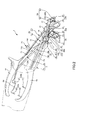
- FIG. 1 is a perspective view sequentially illustrating a method of using the living tissue raising instrument (first embodiment) of the present invention.
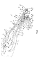
- FIG. 2 is a perspective view sequentially illustrating a method of using the living tissue raising instrument (first embodiment) of the present invention.
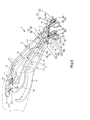
- FIG. 3 is a perspective view sequentially illustrating a method of using the living tissue raising instrument (first embodiment) of the present invention.
- FIG. 4 is a perspective view sequentially illustrating a method of using the living tissue raising instrument (first embodiment) of the present invention.
- FIG. 5 is a perspective view sequentially illustrating a method of using the living tissue raising instrument (first embodiment) of the present invention.
- FIG. 6 is a perspective view sequentially illustrating a method of using the living tissue raising instrument (first embodiment) of the present invention.
- FIG. 1 is a perspective view sequentially illustrating a method of using the living tissue raising instrument (first embodiment) of the present invention.
- FIG. 2 is a perspective view sequentially illustrating a method of using the living tissue raising instrument (
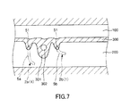
- FIG. 7 is a longitudinal cross-sectional view sequentially illustrating a method of using the living tissue raising instrument (first embodiment) of the present invention.
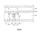
- FIG. 8 is a longitudinal cross-sectional view sequentially illustrating a method of using the living tissue raising instrument (first embodiment) of the present invention.
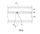
- FIG. 9 is a longitudinal cross-sectional view sequentially illustrating a method of using the living tissue raising instrument (first embodiment) of the present invention.
- FIG. 10 is a cross-sectional view taken along line AA in FIG.
- FIG. 11 is a diagram (side view showing a positional relationship between the first structure and the second structure) seen from the direction of arrow B in FIG. 1.
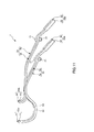
- FIG. 12 is a perspective view showing a second embodiment of the biological tissue raising instrument of the present invention.
- FIG. 13 is a cross-sectional view taken along line CC in FIG. 14 is a cross-sectional view taken along the line DD in FIG.
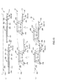
- FIG. 15 is a view (side view showing respective operating states of the first fixing portion and the second fixing portion) seen from the direction of arrow E in FIG.
- FIG. 1 to FIG. 9 are perspective views or longitudinal sectional views sequentially showing how to use the living tissue lifting instrument of the present invention (first embodiment), and FIG. 10 is a sectional view taken along line AA in FIG.
- FIG. 11 is a diagram (side view showing a positional relationship between the first structure and the second structure) seen from the direction of arrow B in FIG. 1.
- the right side in FIGS. 1 to 9 is referred to as “base end” and the left side is referred to as “tip”.
- the biological tissue raising device 1 shown in FIG. 1 to FIG. 8 is used to treat female urinary incontinence, which is one of the treatments for diseases in pelvic organs, that is, when an implant (in-vivo device) is embedded in a living body.
- the vaginal cavity 200 is adjacent to the urethral cavity (the other biological lumen) 100 via the living tissue 300 (see FIGS. 1 and 7 to 10).
- the living tissue 300 includes a wall portion (urethral wall) that defines the urethral cavity 100, a wall portion (vagina wall) that defines the vaginal cavity 200, and the like.
- the thickness of the living tissue 300 is generally about 5 to 20 mm in the case of an adult female, although there are individual differences.
- the implant is a device that is embedded in the living tissue 300 and supports the urethra by pulling it away from the vagina wall in order to treat female urinary incontinence (see FIGS. 9 and 10). As a result, the urethra can be supported, and urine leakage can be prevented.
- the implant for example, a flexible long object can be used.
- the implant is composed of a band 80. This band 80 is called a “sling”.
- the size of the band 80 is not particularly limited and may be set as appropriate.
- the width is preferably about 3 to 15 mm, and the thickness is preferably about 0.2 to 2 mm. .
- constituent material of the belt 80 is not particularly limited.
- various resin materials having biocompatibility can be used.
- the implant is configured by a single band 80.
- the present invention is not limited thereto, and the implant may be configured by a plurality of bands 80, for example.
- the implant is not limited to the band 80, and other long objects having flexibility such as a thread and a string can be used.
- a thread or string is used as the implant and the cross-sectional shape is circular, the diameter is preferably about 0.2 to 5 mm.
- the living tissue raising instrument 1 of the present embodiment includes a first structure 2a that is a first forceps, a second structure 2b that is a second forceps, and a vagina.
- a third structure 3, which is a mirror, and a connecting means 4 for connecting the first structure 2a, the second structure 2b, and the third structure 3 are provided.
- the configuration of each unit will be described.
- the 1st structure 2a is forceps which clamps the biological tissue 300, and has the 1st elongate bodies 5a and 6a.
- the 1st elongate body 5a and the 1st elongate body 6a cross
- the rotation support part 21 used as the rotation center is provided in this cross
- the 1st elongate body 5a and the 1st elongate body 6a are relative via the said rotation support part 21. Can be rotated.
- the position of the rotation support part 21 is the base end side rather than the center part of the longitudinal direction of the 1st elongate bodies 5a and 6a. Thereby, it is possible to ensure the length of the portion of the first elongate body 5a and 6a on the distal end side relative to the rotation support portion 21 as long as possible, so that the portion is relatively deep in the vaginal cavity 200. Can be inserted to the side.
- the rotation support portion 21 is formed on, for example, a shaft protruding from one of the first long bodies 5a and 6a and the other long body, and rotates the shaft. It consists of bearings to support.
- the distal end portion 51 of the first long body 5a and the distal end portion 61 of the first long body 6a protrude in directions opposite to each other. And the 1st elongate body 5a and the 1st elongate body 6a rotate relatively via the rotation support part 21, and the front-end
- the distal end portion 61 of the long body 6a can approach and separate from each other. As shown in FIGS. 4 to 6, when the distal end portions 51 and 61 approach each other, the distal end portions 51 and 61 pinch (pinch) a part of the living tissue 300 from the vaginal cavity 200 side. It becomes a pinched state.
- tip parts 51 and 61 will be closely_contact
- FIG. Further, when the distal end portions 51 and 61 are separated from this sandwiched state, the sandwiched state is released (resolved), and the living tissue 300 can be released.
- the distal end portion 51 of the first elongated body 5a and the distal end portion 61 of the first elongated body 6a are in close contact with the living tissue 300 from the vaginal cavity 200 side.
- a first fixing portion 22a to be fixed is configured.
- a finger hooking portion 52 having a ring shape is provided at the base end portion of the first long body 5a.
- the finger hooking portion 52 is a portion where a finger (for example, a thumb) is inserted inside and the finger is hung.
- a ring-shaped finger hook portion 62 is also provided at the base end portion of the first long body 6a.
- the finger-hanging portion 62 is also a portion where a finger (for example, a middle finger) is inserted inside and the finger is hung.
- the finger-hanging portions 52 and 62 can be approached and separated from each other by putting fingers on the finger-hanging portion 52 of the first long body 5a and the finger-hanging portion 62 of the first long body 6a.
- tip part 61 of the 1st elongate body 6a can also approach / separate, Therefore, A clamping state and a cancellation
- the first fixing portion 22a is fixed to the living tissue 300 by the finger hanging portion 52 of the first elongated body 5a and the finger hanging portion 62 of the first elongated body 6a.
- the first operation portion 23a is configured to operate the first fixing portion 22a, that is, to hold the first fixing portion 22a.
- the finger hanging portion 52 of the first long body 5a has a protruding piece protruding toward the finger hanging portion 62 side of the first long body 6a on the outer peripheral portion thereof. 53 is formed.
- a protruding piece 63 that protrudes toward the finger hanging portion 52 side of the first long body 5a is also formed on the outer periphery of the finger hanging portion 62 of the first long body 6a. The projecting piece 53 and the projecting piece 63 overlap each other.
- the projecting piece 53 is formed with an engaging portion 531 composed of a plurality of uneven portions
- the projecting piece 63 is formed with an engaging portion 631 composed of a plurality of uneven portions.
- the engaging portions 531 and 631 can be engaged at a plurality of locations.
- a rotation angle maintaining unit 24 that temporarily maintains a rotation angle between the first elongated bodies 5a and 6a is configured.
- the engagement between the engaging portions 531 and 631 can be released by separating the protruding piece 53 and the protruding piece 63 from each other.
- the first elongate body 5a has a curve curved downward in FIG. 11 at a portion closest to the proximal end side of the distal end portion 51.
- a portion (escape portion) 54 is formed.
- a curved portion (relief portion) 64 that is curved downward in FIG. 11 is formed at a portion closest to the proximal end side of the distal end portion 61.
- Each of the curved portions 54 and 64 is a portion having a space for receiving the raised portion 301 when the raised portion 301 is formed in the living tissue 300 as will be described later.
- the second structure 2b is a forceps for sandwiching the living tissue 300, and has second elongated bodies 5b and 6b.
- the second elongate body 5b and the second elongate body 6b intersect each other in the longitudinal direction, and a rotation support portion 21 serving as a rotation center is provided at the intersection.
- the second elongate body 5b and the second elongate body 6b are relatively rotatable via the rotation support portion 21.
- the position of the rotation support part 21 is the base end side rather than the center part of the longitudinal direction of the 2nd elongate bodies 5b and 6b. Thereby, it is possible to ensure the length of the portion of the second elongated body 5b and 6b on the distal end side relative to the rotation support portion 21 as long as possible, so that the portion is relatively deep in the vaginal cavity 200. Can be inserted to the side.
- the rotation support portion 21 is formed on, for example, a shaft protruding from one of the second long bodies 5b and 6b and the other long body, and the shaft is rotated. It consists of bearings to support.
- the distal end portion 51 of the second elongated body 5b and the distal end portion 61 of the second elongated body 6b protrude in directions opposite to each other, and the second elongated body 5b and the second elongated body 6b. Can move toward and away from each other.
- FIGS. 5 and 6 when the distal end portions 51 and 61 approach each other, the distal end portions 51 and 61 are in a sandwiched state in which a part of the living tissue 300 is sandwiched from the vaginal cavity 200 side. . Thereby, the front-end
- the distal end portions 51 and 61 are separated from the sandwiched state, the sandwiched state is released and the living tissue 300 can be released.
- the distal end portion 51 of the second elongated body 5b and the distal end portion 61 of the second elongated body 6b are in close contact with the living tissue 300 from the vaginal cavity 200 side.
- a second fixing portion 22b to be fixed is configured.
- the base end of the second elongate body 5b has a ring shape and is provided with a finger hook portion 52 that can be hooked with a finger (for example, a thumb) from the inside.
- a finger hooking portion 62 is provided which can be ring-shaped and can be hooked with a finger (for example, the middle finger) from the inside. Then, the finger-hanging portions 52 and 62 can be moved closer to and away from each other by putting the fingers on the finger-hanging portion 52 of the second long body 5b and the finger-hanging portion 62 of the second long body 6b.
- tip part 61 of the 2nd elongate body 6b can also approach / separate, Therefore, A clamping state and a cancellation
- the second fixing portion 22b is fixed to the living tissue 300 by the finger hanging portion 52 of the second elongated body 5b and the finger hanging portion 62 of the second elongated body 6b.
- a second operation portion 23b for operating the second fixing portion 22b is configured.
- a projecting piece 53 protruding toward the finger hanging portion 62 side of the second elongated body 6b is formed on the outer peripheral portion of the finger hanging portion 52 of the second elongated body 5b. Is formed.
- a projecting piece 63 that protrudes toward the finger hanging portion 52 side of the second elongated body 5b is also formed on the outer peripheral portion of the finger hanging portion 62 of the second elongated body 6b. The projecting piece 53 and the projecting piece 63 overlap each other.
- the projecting piece 53 is formed with an engaging portion 531 composed of a plurality of uneven portions
- the projecting piece 63 is formed with an engaging portion 631 composed of a plurality of uneven portions.
- the engaging portions 531 and 631 can be engaged at a plurality of locations. Accordingly, when the second operating portion 23b is operated to relatively rotate the second elongated bodies 5b and 6b, the rotation angle is kept constant according to the rotation angle. The positional relationship between the second long bodies 5b and 6b can be temporarily maintained. Therefore, even when the finger is released from the second operation portion 23b, the sandwiched state and the released state at the second fixing portion 22b can be maintained.
- the protrusion 53 of the second elongated body 5b and the protrusion 63 of the second elongated body 6b are rotated between the second elongated bodies 5b and 6b.
- a rotation angle maintaining unit 24 that maintains the moving angle temporarily constant is configured.
- the engaging portions 531 and 631 can be engaged with each other by separating the protruding piece 53 and the protruding piece 63 from each other.
- the first structure body 2a and the second structure body 2b configured as described above are such that the second fixing portion 22b is located closer to the base end side than the first fixing portion 22a. 1 is displaced along the direction of insertion into the vaginal cavity 200 (see FIG. 11).
- the operation of the first structure 2a with respect to the first operation part 23a and the operation of the second structure 2b with respect to the second operation part 23b are performed independently of each other. Can do. Accordingly, the first operation unit 23a and the second operation unit 23b can be operated at a desired timing, that is, with a time difference. Therefore, the first operation unit 23a can be operated prior to the second operation unit 23b, that is, the first operation unit 23a can be operated first, and then the second operation unit 23b can be operated. .
- the first fixing portion 22a of the first structure 2a is positioned on the back side of the vaginal cavity 200, and the second fixing portion 22b of the second structure 2b. Is located in front of the vaginal cavity 200.
- the first operation part 23a is operated first, and the first fixing part 22a on the back side of the vaginal cavity 200 is fixed, the second operation part 23b is operated first, This is more preferable than fixing the second fixing portion 22b on the near side of the vaginal cavity 200.
- the reason for this is that when observing the living tissue protuberance device 1 from the vaginal opening and performing treatment, the second operating portion 23b is operated first to fix the second fixing portion 22b, and the second fixing portion 22b is fixed.
- the first fixing portion 22a is hidden by a part of the living tissue 300 to which the fixing portion 22b is fixed (which has been picked by the second fixing portion 22b).
- the first operation unit 23a is operated prior to the second operation unit 23b, such a problem can be reliably prevented.
- the third structure 3 is a colposcope that presses and expands the vaginal cavity 200 from the inside thereof, and includes third elongated bodies 7a and 7b.
- the third long body 7a and the third long body 7b have their base ends intersecting each other.
- the rotation support part 71 used as the rotation center is provided in this cross
- the 3rd elongate body 7a and the 3rd elongate body 7b are relative via the said rotation support part 71.
- the rotation support portion 71 is formed on, for example, a shaft protruding from one of the third long bodies 7a and 7b and the other long body, and rotates the shaft. It consists of bearings to support.
- the third elongate bodies 7 a and 7 b are each formed in a plate-like tongue piece portion (plate-like portion) 72 on the distal end side thereof and on the proximal end side of the tongue piece portion 72, and from the tongue piece portion 72. Can also be divided into a narrow bar-like arm portion 73.
- Each tongue piece portion 72 is a portion inserted into the vaginal cavity 200, and is opposed to each other so as to arrange the first fixing portion 22a and the second fixing portion 22b therebetween.
- the third elongated body 7a and the third elongated body 7b are rotated relative to each other via the rotation support portion 71, so that the tongue pieces 72 can approach and separate from each other.
- each tongue piece part 72 is inserted in the vaginal cavity 200, and it can space apart from each other in this state, and can expand the vaginal cavity 200 from the inner side. Thereby, the predetermined part (target part) of the biological tissue 300 to which the first fixing part 22a of the first structure 2a is fixed and the second fixing part 22b of the second structure 2b are fixed.
- a predetermined portion (target site) of the living tissue 300 can be visually confirmed. In other words, where in the living tissue 300 the first fixing portion 22a of the first structure 2a should be fixed, and where in the living tissue 300 the second fixing portion 22b of the second structure 2b should be fixed. Can be visually confirmed.
- the first fixing part 22a of the first structure 2a is opened and closed and the second fixing part 22b of the second structure 2b is between them. It can be opened and closed.
- each tongue piece 72 has a longitudinal cross-sectional shape that curves outward, and a transverse cross-sectional shape that also curves outward in an arc shape. With such a curved shape, when the vaginal cavity 200 is pushed and widened by each tongue piece portion 72, the living tissue 300 is prevented from being damaged by each tongue piece portion 72.
- a female screw 731 is formed in the middle of the arm portion 73 of the third long body 7b in the longitudinal direction (see FIG. 1).
- a male screw 741 of a bolt 74 is screwed into the female screw 731 from the outside (side) of the arm portion 73.
- bolt 74 is connected with the part inside the arm part 73 of the 3rd elongate body 7a so that rotation is possible.
- the third long body 7b screwed to the bolt 74 is separated from the third long body 7a with the rotation support portion 71 as a fulcrum. It can be displaced in the approaching direction, and as a result, the tongue pieces 72 approach each other. Further, when the bolt 74 is rotated in the opposite direction, the third long body 7b can be displaced in the direction away from the third long body 7a with the rotation support portion 71 as a fulcrum. The tongue pieces 72 are separated from each other. If the rotation operation in any direction with respect to the bolt 74 is stopped, the distance between the tongue pieces 72 is maintained, that is, the approaching state and the separation state of the tongue pieces 72 are maintained. Is done.
- the connecting means 4 has a rod-like body 41 that is integrally formed from the base end portion of the third long body 7a (or the third long body 7b).
- the rod-like body 41 is formed with a through hole 411 penetrating the distal end portion at a distal end portion thereof and a groove 412 penetrating the portion at a proximal end side with respect to the through hole 411.
- an intersection (rotation support portion 21) between the first long bodies 5a and 6a constituting the first structure 2a protrudes in a cylindrical shape toward the side, and an external thread is provided on the outer peripheral portion thereof.
- a shaft 25 formed with is formed.
- the shaft 25 of the first structure 2a is inserted through the through hole 411 of the rod-like body 41, and a nut 42, generally referred to as a “wing nut”, is screwed in the inserted state. .
- the 1st structure 2a is connected and supported.
- the rod-like body 41 (through hole 411), the nut 42, and the shaft 25 constitute the first support portion 44a that supports the first structure 2a.
- first support portion 44a can also support the first structure 2a so as to be rotatable around the shaft 25 if the nut 42 is loosened by rotating it in a predetermined direction.
- the intersecting portion (rotating support portion 21) between the second long bodies 5b and 6b constituting the second structure 2b also projects in a cylindrical shape toward the side, and a male screw is formed on the outer peripheral portion thereof.
- a shaft 26 is formed.
- the shaft 26 of the second structure 2b is inserted through the groove 412 of the rod-like body 41, and a nut 43, generally referred to as a “wing nut”, is screwed in the inserted state. Thereby, the 2nd structure 2b is connected and supported.
- the rod-like body 41 (groove 412), the nut 43, and the shaft 26 constitute a second support portion 44 b that supports the second structure 2 b.
- the second support portion 44b supports the second structure 2b so as to be movable along the longitudinal direction of the rod-shaped body 41 (formation direction of the groove 412) when the nut 43 is loosened by rotating it in a predetermined direction.
- the second structure 2b can be supported so as to be rotatable around the shaft 26. By this movement, the second structure 2b can be moved closer to and away from the first structure 2a, and as a result, the second fixed portion 22b can also be reliably approached to the first fixed portion 22a. ⁇ It will be separated. Further, the rotation of the second structure 2b can be performed independently of the rotation of the first structure 2a.
- the second support portion 44b can restrict (stop) the movement of the second structure 2b at the tightened position when the nut 43 is rotated and tightened in the opposite direction to the above. It is also possible to keep the turning angle of the second structure 2b at a constant time. And by this movement restriction
- the 2nd support part 44b also has a function also as a locking means which maintains the said distance temporarily constant.
- connection means 4 it does not specifically limit as a constituent material of the 1st structure 2a, the 2nd structure 2b, the 3rd structure 3, and the connection means 4,
- metal materials such as stainless steel, are used. Can do.
- a living tissue protuberance device 1 is prepared.
- the living tissue raising device 1 is in a state where the first fixing portion 22a is closed, that is, the distal end portion 51 of the first long body 5a and the first long body 6a. It is in the state where the front-end
- the second fixing portion 22b is closed, that is, the tip 51 of the second elongated body 5b and the tip 61 of the second elongated body 6b are closest. It has become a state.
- the second structure 2b at this time is not limited to the state in which the second fixing portion 22b is closed, and the second fixing portion 22b is in an open state, that is, the second length.
- the tip 51 of the scale 5b and the tip 61 of the second long body 6b may be in the most separated state.
- the tongue pieces 72 are in the closest state.
- the inclination (angle) of each is appropriately adjusted by the woman to be treated. The adjustment is performed by loosening the nut 42 of the first support portion 44a of the connecting means 4 and loosening the nut 43 of the second support portion 44b. After the adjustment, the nuts 42 and 43 are tightened.
- the living tissue protuberance device 1 is inserted into the vaginal cavity 200 from its distal end side. This insertion is performed until the vicinity of each boundary portion between the tongue piece portion 72 and the arm portion 73 of the third elongated body 7a, 7b in the third structure 3 is located at the vaginal opening.
- the first structural body 2a includes a curved portion 54 of the first elongated body 5a and a curved portion 64 of the first elongated body 6a, respectively. It is located on the tip side of the fixed portion 22b.
- the bending direction of each of the bending portions 54 and 64 is a direction facing away from the urethral cavity 100.
- the bolt 74 of the third structural body 3 is rotated to widen the gap between the tongue pieces 72 of the third elongated bodies 7a and 7b. Thereby, the state in which the vaginal cavity 200 is pressed and expanded is maintained. Therefore, when performing the subsequent operation on the living tissue elevation device 1, a visual field for observing the inside of the vaginal cavity 200 is secured, The operation can be performed while fixing the tissue raising device 1.
- the first operation unit 23 a of the first structure 2 a is operated, and a part of the living tissue 300 is held by the first fixing unit 22 a.
- fixed part 22a will be in the clamping state (state fixed to the biological tissue 300).
- this clamping state is maintained by the rotation angle maintenance part 24 of the 1st structure 2a mentioned above.
- the second structure 2 b is moved toward the distal end, that is, toward the back side of the vaginal cavity 200.
- the first fixed portion 22a in the sandwiched state and the second fixed portion 22b in the sandwiched state come close to each other.
- fixed part 22b of the biological tissue 300 is wrinkled toward the direction which approaches the 1st fixing
- the nut 43 is tightened again to restrict the displacement of the second structure 2b.
- fixed part 22b can be temporarily maintained constant, Therefore The formation state of the protruding part 301 can also be maintained.
- the raised portion 301 is peeled off, and a puncture needle (not shown) which is a long medical instrument is used to connect the peeled raised portion 301 and the outside to a closed hole.
- a puncture hole 302 that communicates with each other is formed.
- the raised portion 301 where the peeling operation and the puncturing operation are performed is raised to such an extent that these operations are sufficient. Therefore, in the living tissue bulging device 1, when performing a surgical treatment (the peeling operation and the puncturing operation in the present embodiment) on the bulging portion 301, the treatment can be easily and reliably performed.
- the space for the puncture needle (treatment instrument) to pass (inserted) from the base end side (hand operation side) is the longitudinal direction of the first long body 5a and the second long body 5b. Is secured along.
- the band 80 is passed through the puncture hole 302 using, for example, a guide wire (not shown).
- the band 80 is in a state in which both ends thereof protrude from the puncture hole 302 to the outside of the body with the urethra wall (the raised portion 301) hooked.
- the living tissue protuberance device 1 is removed from the vaginal cavity 200.
- the first operating portion 23a of the first structure 2a is operated to release the first fixing portion 22a in the clamping state, and the second structure 2b 2 operation part 23b is operated and the 2nd fixing
- the bolts 74 of the third structure 3 is operated to bring the tongue pieces 72 close to each other and releasing the pressure on the vaginal cavity 200.
- the biological tissue 300 is removed from the raised portion 301, that is, restored to the original state (shape).
- biological tissue raising instrument 1 demonstrated in this embodiment the case where it is used when implanting the implantable implant for the treatment of female urinary incontinence in a living body, it is not limited to this, Also used for applications.
- FIG. 12 is a perspective view showing a second embodiment of the biological tissue raising instrument of the present invention
- FIG. 13 is a cross-sectional view taken along the line CC in FIG. 12
- FIG. 14 is a cross-sectional view taken along the line DD in FIG. 15 is a view (side view showing respective operating states of the first fixing portion and the second fixing portion) as seen from the direction of arrow E in FIG.
- the right side in FIGS. 12 and 15 is referred to as “base end”, and the left side is referred to as “tip”.
- the upper side in FIGS. 12 to 15 is referred to as “upper” or “upper”
- the lower side is referred to as “upper” or “lower”.
- This embodiment is the same as the first embodiment except that the overall shape of the biological tissue raising device is different.
- the living tissue raising device 1A of the present embodiment includes a first elongate body 8c arranged so as to be substantially parallel to the insertion direction of the living tissue raising device 1A into the vaginal cavity 200, A first structure 2c having 9c and a first fixing portion 20a, and second elongated bodies 8d and 9d and a second fixing portion 20b arranged so as to be substantially parallel to the insertion direction.
- the second structural body 2d has a third structural body 3a having a plate-like tongue piece (plate-shaped portion) 10 and a connecting means 4a.
- the first long body 8 c and the first long body 9 c are connected to each other through the connecting portion 27 at the distal ends thereof. And between the 1st elongate body 8c and the 1st elongate body 9c, the 1st fixing
- an extension portion 11 extending downward is provided in the vicinity of the base end portion of the first long body 8c.
- the extension part 11 functions as a gripping part that is gripped when operating the living tissue raising instrument 1A.
- a protruding portion 81 having a plate shape protruding downward is formed at the base end portion of the first elongated body 8c.
- the protruding portion 81 is formed with a slit 811 that engages with a first operation portion 14a formed of a first linear body to be described later.
- the base end portion of the first elongated body 9c is provided with an extension portion 12 that extends downward in FIG.
- the second long body 8d and the second long body 9d are connected to each other through the connecting portions 28 at their distal ends. And between the 2nd elongate body 8d and the 2nd elongate body 9d, the 2nd fixing
- the second fixed portion 20b has a base end portion 207 fixed between the second elongated body 8d and the second elongated body 9d.
- a protruding portion 82 having a plate shape protruding upward is formed at the base end portion of the second elongated body 8d.
- the protruding portion 82 is formed with a slit 821 that engages with a second operation portion 14b formed of a second linear body to be described later.
- the first structure 2c and the second structure 2d as described above are formed on the first structure 2c (first elongated bodies 8c, 9c) on the second structure 2d (second The long bodies 8d and 9d) are overlapped. And the 2nd structure 2d can slide on the 1st structure 2c along the longitudinal direction. By this sliding, the first fixing portion 20a of the first structure 2c and the second fixing portion 20b of the second structure 2d can approach and separate from each other.
- a bolt 13 is screwed in the middle of the second long body 8d of the second structure 2d in the longitudinal direction.
- the tip 131 of the bolt 13 comes into pressure contact with the upper surface 83 of the first elongated body 8c of the first structure 2c, and the second The movement of the structure 2d with respect to the first structure 2c is prevented (see FIG. 14).
- fixed part 20b can be temporarily maintained constant.
- the bolt 13 is a member that functions as a locking means that temporarily maintains a constant distance between the first fixing portion 20a and the second fixing portion 20b.
- first fixing portion 20a and the second fixing portion 20b have substantially the same configuration, the first fixing portion 20a will be described below representatively.
- the first fixing portion 20 a has grooves 203 and 204 formed on the lower surface 201 and grooves 205 formed on the upper surface 202.
- the grooves 203 to 205 are arranged at intervals in this order from the front end side.
- the portions where the grooves 203 to 205 are formed become fragile and deformable portions (thin fragile portions), and can be bent at the portions.
- fixed part 20a can take the bent state (refer FIG.15 (b), (c)) and the expand
- the first fixing unit 20a can be in close contact with the living tissue 300 in the bent state, and is separated from the living tissue 300 in the expanded state.
- an uneven portion 206 constituted by a plurality of grooves engaging with the living tissue 300 is formed in a portion of the first fixing portion 20a that is in close contact with the living tissue 300.
- the first fixing portion 20 a is fixed in close contact with the living tissue 300 by engaging the uneven portion 206 with the living tissue 300.
- the operation with respect to the first fixing unit 20a is performed by the first operation unit 14a formed of the first linear body.
- the connecting portion 208 is inserted into a guide groove (not shown) formed in the first long body 8c and can move along the guide groove. Then, as shown in FIG. 15, when a pulling operation is performed on the first operation portion 14a, the first fixing portion 20a can shift from the expanded state to the bent state.
- the first operation portion 14a is temporarily inserted into and engaged with the slit 811 of the protruding portion 81 of the first elongated body 8c. Can be maintained.
- the operation with respect to the second fixing portion 20b is performed by the second operation portion 14b formed of the second linear body.
- the connecting portion 208 is inserted into a guide groove (not shown) formed in the second elongate body 8d and can move along the guide groove. Then, as shown in FIG. 15, when the pulling operation is performed on the second operation portion 14b, the second fixing portion 20b can be shifted from the expanded state to the bent state.
- the second operating portion 14b is inserted into the slit 821 of the protruding portion 82 of the second elongated body 8d to be engaged with each other temporarily. Can be maintained.
- the third structure 3 a has a tongue piece 10.
- the tongue piece 10 is disposed below the first structure 2c.
- the tongue piece portion 10 is formed of a member having an elongated shape that is substantially the same length as the first elongated body 8c and the first elongated body 9c of the first structure 2c, and its cross-sectional shape Is curved in an arc shape downward (outside).
- the third structure 3 a includes an extension portion 15 extending downward from the base end portion of the tongue piece portion 10, and an upward direction from the base end portion of the tongue piece portion 10. It has a pair of protrusion parts 16a and 16b which protruded toward.
- the extension portion 15 functions as a gripping portion that is gripped together with the extension portion 11 when operating the living tissue raising instrument 1A.
- the protruding portion 16a overlaps with the extension portion 11 of the first structure 2c from the inside, and is connected by a rotation support portion 45a constituting a part of the connecting means 4a.
- the protruding portion 16b overlaps the extension portion 12 of the first structure 2c from the inside, and is connected by a rotation support portion 45b that constitutes a part of the connecting means 4a.
- a female screw 111 is formed in the extension portion 11, and a male screw 171 of the bolt 17 is screwed from the base end side.
- bolt 17 is connected with the part which faces the base end side of the extension part 15 of the 3rd structure 3a so that rotation is possible.
- the tongue piece portion 10 approaches the first structure 2c and the second structure 2d with the rotation support portions 45a and 45b as fulcrums.
- the tongue piece 10 and the first structure body 2c and the second structure body 2d approach each other.
- the tongue piece 10 rotates in a direction away from the first structure 2c and the second structure 2d with the rotation support portions 45a and 45b as fulcrums.
- the tongue piece 10 is separated from the first structure 2c and the second structure 2d.
- the connecting means 4a includes one of the first structure 2c and the second structure 2d (the second structure 2d in the configuration shown in FIGS. 12 to 14). ) And a pair of claws 46a and 46b engaged with the other (first structure 2c in the configuration shown in FIGS. 12 to 14).
- the claw 46a is disposed in the vicinity of the distal end portion of the second elongated body 8d
- the claw 46b is disposed in the vicinity of the distal end portion of the second elongated body 9d.
- fixed part 20b are each in the expansion
- fixed part 20b are each in the expansion
- the first operation unit 14a for operating the first fixing unit 20a and the second operation unit 14b for operating the second fixing unit 20b are respectively pulled.
- the first fixing portion 20a shifts from the expanded state to the bent state
- the concavo-convex portion 206 engages with the living tissue 300
- the second fixed portion 20b also shifts from the expanded state to the bent state.
- the uneven part 206 engages with the living tissue 300.
- each pulling operation with respect to the 1st operation part 14a and the 2nd operation part 14b may be performed simultaneously, and may be performed with a time difference.
- the second fixing portion 20b is moved closer to the first fixing portion 20a.
- the raised portion 301 is reliably formed in the portion between the first fixed portion 20a and the second fixed portion 20b of the living tissue 300, and a surgical treatment can be performed on the raised portion 301. it can.
- the 1st structure 2c and the 2nd structure 2d may be supported so that relative rotation is possible.
- each part which comprises a biological tissue raising instrument is arbitrary which can exhibit the same function. It can be replaced with the configuration of Moreover, arbitrary components may be added.
- the living tissue raising device of the present invention may be a combination of any two or more configurations (features) of the above embodiments.
- the biological tissue lifting instrument of the present invention is a biological tissue lifting instrument that is used by being inserted into one of the two biological lumens adjacent to each other through the biological tissue.
- a first structure having a first fixing portion that is closely fixed from the one living body lumen side, and the one living tube on the living tissue on a proximal side of the first fixing portion;
- the second structure having a second fixing portion that is closely fixed from the cavity side, the first fixing portion, and the second fixing portion being able to approach and separate from each other.
- the portion of the tissue between the first fixed portion and the second fixed portion is the two living And it is configured so as to bulge in a direction away from the other of the biological lumen of the lumen. Therefore, when a surgical procedure is performed on a living tissue between two living lumens, the procedure can be performed easily and reliably. Therefore, the biological tissue raising instrument of the present invention has industrial applicability.
Landscapes
- Health & Medical Sciences (AREA)
- Life Sciences & Earth Sciences (AREA)
- Surgery (AREA)
- Animal Behavior & Ethology (AREA)
- General Health & Medical Sciences (AREA)
- Engineering & Computer Science (AREA)
- Biomedical Technology (AREA)
- Heart & Thoracic Surgery (AREA)
- Veterinary Medicine (AREA)
- Public Health (AREA)
- Vascular Medicine (AREA)
- Reproductive Health (AREA)
- Nuclear Medicine, Radiotherapy & Molecular Imaging (AREA)
- Urology & Nephrology (AREA)
- Medical Informatics (AREA)
- Molecular Biology (AREA)
- Cardiology (AREA)
- Oral & Maxillofacial Surgery (AREA)
- Transplantation (AREA)
- Gynecology & Obstetrics (AREA)
- Pregnancy & Childbirth (AREA)
- Surgical Instruments (AREA)
Description
(1) 生体組織を介して互いに隣接する2本の生体管腔のうちの一方の生体管腔内に挿入して用いられる生体組織隆起器具であって、
前記生体組織に前記一方の生体管腔側から密着して固定される第1の固定部を有する第1の構造体と、
前記第1の固定部よりも基端側で前記生体組織にその前記一方の生体管腔側から密着して固定される第2の固定部を有する第2の構造体と、
前記第1の固定部と前記第2の固定部とが互いに接近・離間可能に、前記第1の構造体と前記第2の構造体とを連結する連結手段とを備え、
前記第1の固定部および前記第2の固定部がそれぞれ前記生体組織に固定された状態で互いに接近することにより、前記生体組織の前記第1の固定部と前記第2の固定部との間の部分を、前記2本の生体管腔のうちの他方の生体管腔から遠ざかる方向に隆起させるよう構成されていることを特徴とする生体組織隆起器具。
前記第1の固定部および前記第2の固定部は、それぞれ、前記各長尺体の先端部で構成され、該各先端部同士は、前記各長尺体同士が相対的に回動することにより接近・離間して、その接近した際に前記生体組織を挟持し、これにより、前記生体組織に密着して固定される上記(1)または(2)に記載の生体組織隆起器具。
前記第1の固定部および前記第2の固定部は、それぞれ、前記2本の長尺体の間に架設された板部材で構成され、該板部材は、折り曲げられて前記生体組織に密着する折り曲げ状態を取り得る上記(1)に記載の生体組織隆起器具。
前記連結手段は、前記第1の構造体を構成する前記各長尺体と前記第2の構造体を構成する前記各長尺体とのうちの一方に突出形成され、他方に係合する爪を有する上記(8)ないし(11)のいずれかに記載の生体組織隆起器具。
前記第2の構造体は、前記第2の固定部が前記生体組織に固定されるよう前記第2の固定部を操作する第2の操作部を有し、
前記第1の操作部と前記第2の操作部とは、互いに独立して操作可能である上記(1)ないし(12)のいずれかに記載の生体組織隆起器具。
骨盤内臓器における疾患の治療に用いられるものである上記(1)ないし(20)のいずれかに記載の生体組織隆起器具。
図1~図9は、それぞれ、本発明の生体組織隆起器具(第1実施形態)の使用方法を順に示す斜視図または縦断面図、図10は、図9中のA-A線断面図、図11は、図1中の矢印B方向から見た図(第1の構造体と第2の構造体との位置関係を示す側面図)である。なお、以下では、説明の都合上、図1~図9中の右側を「基端」、左側を「先端」と言う。
第1の構造体2aは、生体組織300を挟持する鉗子であり、第1の長尺体5aおよび6aを有している。第1の長尺体5aと第1の長尺体6aとは、互いにその長手方向の途中で交差している。そして、この交差部に、回動中心となる回動支持部21が設けられ、当該回動支持部21を介して、第1の長尺体5aと第1の長尺体6aとが相対的に回動可能となっている。
図1~図6、図11に示すように、第2の構造体2bは、生体組織300を挟持する鉗子であり、第2の長尺体5bおよび6bを有している。第2の長尺体5bと第2の長尺体6bとは、互いにその長手方向の途中で交差し、この交差部に、回動中心となる回動支持部21が設けられている。第2の長尺体5bと第2の長尺体6bとは、この回動支持部21を介して、相対的に回動可能となっている。
図1~図6に示すように、第3の構造体3は、膣腔200をその内側から押圧して拡大する膣鏡であり、第3の長尺体7a、7bを有している。第3の長尺体7aと第3の長尺体7bとは、互いにその基端部同士が交差している。そして、この交差部に、回動中心となる回動支持部71が設けられ、当該回動支持部71を介して、第3の長尺体7aと第3の長尺体7bとが相対的に回動可能となっている。なお、回動支持部71は、例えば、第3の長尺体7aおよび7bのうちの一方の長尺体から突出形成された軸と、他方の長尺体に形成され、当該軸を回動支持する軸受けとで構成されている。
連結手段4は、第3の長尺体7a(または第3の長尺体7b)の基端部から一体的に形成された棒状体41を有している。棒状体41には、その先端部に当該先端部を貫通する貫通孔411と、貫通孔411よりも基端側の部分に当該部分を貫通する溝412とが形成されている。
また、第3の構造体3では、各舌片部72同士が最も接近した状態となっている。
その後、帯80の不要な部分を切除し、所定の縫合等を行なって手技を終了する。
図12は、本発明の生体組織隆起器具の第2実施形態を示す斜視図、図13は、図12中のC-C線断面図、図14は、図12中のD-D線断面図、図15は、図12中の矢印E方向から見た図(第1の固定部および第2の固定部のそれぞれの作動状態を示す側面図)である。なお、以下では、説明の都合上、図12および図15中の右側を「基端」、左側を「先端」と言う。また、図12~図15中の上側を「上」または「上方」、下を「上」または「下方」と言う。
そのため、2本の生体管腔の間の生体組織に対して外科的処置を施す際、その処置を容易かつ確実に行なうことができる。
従って、本発明の生体組織隆起器具は、産業上の利用可能性を有する。
2a、2c 第1の構造体
2b、2d 第2の構造体
21 回動支持部
22a 第1の固定部
22b 第2の固定部
23a 第1の操作部
23b 第2の操作部
24 回動角度維持部
25、26 軸
27、28 連結部
3、3a 第3の構造体
4、4a 連結手段
41 棒状体
411 貫通孔
412 溝
42、43 ナット
44a 第1の支持部
44b 第2の支持部
45a、45b 回動支持部
46a、46b 爪
5a 第1の長尺体
5b 第2の長尺体
51 先端部
52 指掛け部
53 突片
531 係合部
54 湾曲部(逃げ部)
6a 第1の長尺体
6b 第2の長尺体
61 先端部
62 指掛け部
63 突片
631 係合部
64 湾曲部(逃げ部)
7a、7b 第3の長尺体
71 回動支持部
72 舌片部(板状部)
73 アーム部
731 雌ネジ
74 ボルト
741 雄ネジ
8c 第1の長尺体
8d 第2の長尺体
81 突出部
811 スリット
82 突出部
821 スリット
83 上面
9c 第1の長尺体
9d 第2の長尺体
10 舌片部(板状部)
11 延長部
111 雌ネジ
12 延長部
13 ボルト
131 先端
14a 第1の操作部
14b 第2の操作部
15 延長部
16a、16b 突出部
17 ボルト
171 雄ネジ
20a 第1の固定部
20b 第2の固定部
201 下面
202 上面
203、204、205 溝
206 凹凸部
207 基端部
208 連結部
80 帯
100 尿道腔(他方の生体管腔)
200 膣腔(一方の生体管腔)
300 生体組織
301 隆起部
302 穿刺孔
Claims (21)
- 生体組織を介して互いに隣接する2本の生体管腔のうちの一方の生体管腔内に挿入して用いられる生体組織隆起器具であって、
前記生体組織に前記一方の生体管腔側から密着して固定される第1の固定部を有する第1の構造体と、
前記第1の固定部よりも基端側で前記生体組織にその前記一方の生体管腔側から密着して固定される第2の固定部を有する第2の構造体と、
前記第1の固定部と前記第2の固定部とが互いに接近・離間可能に、前記第1の構造体と前記第2の構造体とを連結する連結手段とを備え、
前記第1の固定部および前記第2の固定部がそれぞれ前記生体組織に固定された状態で互いに接近することにより、前記生体組織の前記第1の固定部と前記第2の固定部との間の部分を、前記2本の生体管腔のうちの他方の生体管腔から遠ざかる方向に隆起させるよう構成されていることを特徴とする生体組織隆起器具。 - 前記第1の構造体および前記第2の構造体のうちの少なくとも一方は、前記生体組織の隆起した部分を受け入れる空間を有する請求項1に記載の生体組織隆起器具。
- 前記第1の構造体および前記第2の構造体は、それぞれ、2本の長尺体を有し、該2本の長尺体同士がその長手方向の途中で交差し、その交差部が回動可能に支持されたものであり、
前記第1の固定部および前記第2の固定部は、それぞれ、前記各長尺体の先端部で構成され、該各先端部同士は、前記各長尺体同士が相対的に回動することにより接近・離間して、その接近した際に前記生体組織を挟持し、これにより、前記生体組織に密着して固定される請求項1または2に記載の生体組織隆起器具。 - 手元操作側から処置具を挿入するスペースを有する請求項3に記載の生体組織隆起器具。
- 前記第1の構造体を構成する前記各長尺体は、それぞれ、その先端側の部分が、前記他方の生体管腔から遠ざかる方向に向かって湾曲している請求項3または4に記載の生体組織隆起器具。
- 前記第1の構造体および前記第2の構造体は、それぞれ、前記各長尺体同士が相対的に回動した際、その回動角度を一時的に一定に維持するよう構成されている請求項3ないし5のいずれか1項に記載の生体組織隆起器具。
- 前記連結手段は、棒状体を有し、該棒状体の先端部で、前記第1の構造体を構成する前記各長尺体同士の前記交差部を支持し、前記棒状体の長手方向に沿って、前記第2の構造体を構成する前記各長尺体同士の前記交差部を移動可能に支持するものである請求項3ないし6のいずれか1項に記載の生体組織隆起器具。
- 前記第1の構造体および前記第2の構造体は、それぞれ、当該生体組織隆起器具の前記一方の生体管腔への挿入方向と平行となるように配置された2本の長尺体を有し、
前記第1の固定部および前記第2の固定部は、それぞれ、前記2本の長尺体の間に架設された板部材で構成され、該板部材は、折り曲げられて前記生体組織に密着する折り曲げ状態を取り得る請求項1に記載の生体組織隆起器具。 - 前記板部材は、展開して前記生体組織から離間する展開状態を取り得る請求項8に記載の生体組織隆起器具。
- 前記板部材は、前記生体組織に密着する部分に該生体組織に係合する凹凸部が形成されている請求項8または9に記載の生体組織隆起器具。
- 前記第1の構造体および前記第2の構造体は、それぞれ、前記折り曲げ状態と前記展開状態とを一時的に維持するよう構成されている請求項8ないし10のいずれか1項に記載の生体組織隆起器具。
- 前記第1の構造体を構成する前記各長尺体上に、前記第2の構造体を構成する前記各長尺体がその長手方向に沿って摺動可能に重なっており、
前記連結手段は、前記第1の構造体を構成する前記各長尺体と前記第2の構造体を構成する前記各長尺体とのうちの一方に突出形成され、他方に係合する爪を有する請求項8ないし11のいずれか1項に記載の生体組織隆起器具。 - 前記第1の構造体は、前記第1の固定部が前記生体組織に固定されるよう前記第1の固定部を操作する第1の操作部を有し、
前記第2の構造体は、前記第2の固定部が前記生体組織に固定されるよう前記第2の固定部を操作する第2の操作部を有し、
前記第1の操作部と前記第2の操作部とは、互いに独立して操作可能である請求項1ないし12のいずれか1項に記載の生体組織隆起器具。 - 前記第1の操作部は、前記第1の構造体の基端側に配置され、前記第2の操作部は、前記第2の構造体の基端側に配置されている請求項13に記載の生体組織隆起器具。
- 前記第1の固定部と前記第2の固定部との距離を一時的に一定に維持するロック手段をさらに備える請求項1ないし14のいずれか1項に記載の生体組織隆起器具。
- 前記連結手段は、前記第1の構造体を回動可能に支持する第1の支持部と、前記第2の構造体を前記第1の構造体と独立して回動可能に支持する第2の支持部とを有する請求項1ないし15のいずれか1項に記載の生体組織隆起器具。
- 前記第1の支持部は、前記第1の構造体の回動角度を一時的に一定に維持するよう構成され、前記第2の支持部は、前記第2の構造体の回動角度を一時的に一定に維持するよう構成されている請求項16に記載の生体組織隆起器具。
- 前記一方の生体管腔を拡大する第3の構造体をさらに備える請求項1ないし17のいずれか1項に記載の生体組織隆起器具。
- 前記第3の構造体が前記一方の生体管腔を拡大した状態で該一方の生体管腔内を長尺な医療器具が通過可能となる請求項18に記載の生体組織隆起器具。
- 前記第3の構造体は、板状をなす少なくとも1枚の板状部を有する請求項18または19に記載の生体組織隆起器具。
- 前記2本の生体管腔のうちの一方の生体管腔は、膣腔であり、他方の生体管腔は、尿道腔であり、
骨盤内臓器における疾患の治療に用いられるものである請求項1ないし20のいずれか1項に記載の生体組織隆起器具。
Applications Claiming Priority (2)
| Application Number | Priority Date | Filing Date | Title |
|---|---|---|---|
| JP2011284390 | 2011-12-26 | ||
| JP2011-284390 | 2011-12-26 |
Publications (1)
| Publication Number | Publication Date |
|---|---|
| WO2013099342A1 true WO2013099342A1 (ja) | 2013-07-04 |
Family
ID=48696856
Family Applications (1)
| Application Number | Title | Priority Date | Filing Date |
|---|---|---|---|
| PCT/JP2012/069688 Ceased WO2013099342A1 (ja) | 2011-12-26 | 2012-08-02 | 生体組織隆起器具 |
Country Status (1)
| Country | Link |
|---|---|
| WO (1) | WO2013099342A1 (ja) |
Citations (3)
| Publication number | Priority date | Publication date | Assignee | Title |
|---|---|---|---|---|
| JP2006506193A (ja) * | 2002-11-19 | 2006-02-23 | ヴァスキュラー・コントロール・システムズ・インコーポレーテッド | 膣内手術のための支持鉤状器具 |
| WO2007047813A2 (en) * | 2005-10-19 | 2007-04-26 | Ams Research Corporation | Needle delivery system for electrodes |
| JP2007521851A (ja) * | 2003-11-25 | 2007-08-09 | バスキュラー・コントロール・システムズ・インコーポレイテッド | 非対称性子宮動脈構造のための閉塞器具 |
-
2012
- 2012-08-02 WO PCT/JP2012/069688 patent/WO2013099342A1/ja not_active Ceased
Patent Citations (3)
| Publication number | Priority date | Publication date | Assignee | Title |
|---|---|---|---|---|
| JP2006506193A (ja) * | 2002-11-19 | 2006-02-23 | ヴァスキュラー・コントロール・システムズ・インコーポレーテッド | 膣内手術のための支持鉤状器具 |
| JP2007521851A (ja) * | 2003-11-25 | 2007-08-09 | バスキュラー・コントロール・システムズ・インコーポレイテッド | 非対称性子宮動脈構造のための閉塞器具 |
| WO2007047813A2 (en) * | 2005-10-19 | 2007-04-26 | Ams Research Corporation | Needle delivery system for electrodes |
Similar Documents
| Publication | Publication Date | Title |
|---|---|---|
| JP6092367B2 (ja) | 穿刺装置 | |
| JP6155252B2 (ja) | 穿刺器具および穿刺装置 | |
| WO2014013591A1 (ja) | 穿刺装置 | |
| KR20190133719A (ko) | 조직 퇴축을 위한 장치 및 방법 | |
| WO2012126477A1 (en) | Fastening device, related tools and methods | |
| US12161540B2 (en) | Implant fixation devices and methods of using the same | |
| CN101861129A (zh) | 用于塑造或提拉人体中正常或扩张组织的装置 | |
| JP2007536981A (ja) | 拡張蛇行静脈を治療する装置と方法 | |
| CN104321035B (zh) | 医疗用管及医疗用管组装体 | |
| JP2012510865A (ja) | 骨盤床移植片を送達するための方法およびデバイス | |
| CN117159055A (zh) | 粘膜提起系统 | |
| AU2009293295A1 (en) | Suture retriever-sheath dilator tool and method for use thereof | |
| JP5972895B2 (ja) | 固定器具 | |
| WO2013077031A1 (ja) | 拡張器具 | |
| US10117738B2 (en) | Atraumatic tip geometry for indwelling devices | |
| WO2013186907A1 (ja) | 穿刺装置 | |
| US20060052800A1 (en) | Surgical tool for incontinence sling implantation | |
| WO2019034661A1 (en) | ABDOMINAL INSTRUMENT AND METHOD | |
| WO2014162422A1 (ja) | 穿刺針組立体 | |
| JP2010268865A (ja) | 圧排器具 | |
| WO2013176100A1 (ja) | 組織剥離装置 | |
| WO2013046963A1 (ja) | インプラントおよびインプラント装置 | |
| WO2014162425A1 (ja) | 医療用具 | |
| WO2014162427A1 (ja) | 挿入具および穿刺装置 | |
| JP2013183832A (ja) | 生体組織隆起器具 |
Legal Events
| Date | Code | Title | Description |
|---|---|---|---|
| 121 | Ep: the epo has been informed by wipo that ep was designated in this application |
Ref document number: 12863042 Country of ref document: EP Kind code of ref document: A1 |
|
| NENP | Non-entry into the national phase |
Ref country code: DE |
|
| 122 | Ep: pct application non-entry in european phase |
Ref document number: 12863042 Country of ref document: EP Kind code of ref document: A1 |
|
| NENP | Non-entry into the national phase |
Ref country code: JP |
|
| 122 | Ep: pct application non-entry in european phase |
Ref document number: 12863042 Country of ref document: EP Kind code of ref document: A1 |