WO2013085060A1 - トレランスリング、ハードディスク装置およびハードディスク装置の製造方法 - Google Patents
トレランスリング、ハードディスク装置およびハードディスク装置の製造方法 Download PDFInfo
- Publication number
- WO2013085060A1 WO2013085060A1 PCT/JP2012/081987 JP2012081987W WO2013085060A1 WO 2013085060 A1 WO2013085060 A1 WO 2013085060A1 JP 2012081987 W JP2012081987 W JP 2012081987W WO 2013085060 A1 WO2013085060 A1 WO 2013085060A1
- Authority
- WO
- WIPO (PCT)
- Prior art keywords
- tolerance ring
- circumferential direction
- end portion
- hard disk
- notch
- Prior art date
- Legal status (The legal status is an assumption and is not a legal conclusion. Google has not performed a legal analysis and makes no representation as to the accuracy of the status listed.)
- Ceased
Links
Images






Classifications
-
- F—MECHANICAL ENGINEERING; LIGHTING; HEATING; WEAPONS; BLASTING
- F16—ENGINEERING ELEMENTS AND UNITS; GENERAL MEASURES FOR PRODUCING AND MAINTAINING EFFECTIVE FUNCTIONING OF MACHINES OR INSTALLATIONS; THERMAL INSULATION IN GENERAL
- F16C—SHAFTS; FLEXIBLE SHAFTS; ELEMENTS OR CRANKSHAFT MECHANISMS; ROTARY BODIES OTHER THAN GEARING ELEMENTS; BEARINGS
- F16C35/00—Rigid support of bearing units; Housings, e.g. caps, covers
-
- F—MECHANICAL ENGINEERING; LIGHTING; HEATING; WEAPONS; BLASTING
- F16—ENGINEERING ELEMENTS AND UNITS; GENERAL MEASURES FOR PRODUCING AND MAINTAINING EFFECTIVE FUNCTIONING OF MACHINES OR INSTALLATIONS; THERMAL INSULATION IN GENERAL
- F16C—SHAFTS; FLEXIBLE SHAFTS; ELEMENTS OR CRANKSHAFT MECHANISMS; ROTARY BODIES OTHER THAN GEARING ELEMENTS; BEARINGS
- F16C27/00—Elastic or yielding bearings or bearing supports, for exclusively rotary movement
- F16C27/02—Sliding-contact bearings
-
- F—MECHANICAL ENGINEERING; LIGHTING; HEATING; WEAPONS; BLASTING
- F16—ENGINEERING ELEMENTS AND UNITS; GENERAL MEASURES FOR PRODUCING AND MAINTAINING EFFECTIVE FUNCTIONING OF MACHINES OR INSTALLATIONS; THERMAL INSULATION IN GENERAL
- F16D—COUPLINGS FOR TRANSMITTING ROTATION; CLUTCHES; BRAKES
- F16D1/00—Couplings for rigidly connecting two coaxial shafts or other movable machine elements
- F16D1/06—Couplings for rigidly connecting two coaxial shafts or other movable machine elements for attachment of a member on a shaft or on a shaft-end
- F16D1/08—Couplings for rigidly connecting two coaxial shafts or other movable machine elements for attachment of a member on a shaft or on a shaft-end with clamping hub; with hub and longitudinal key
- F16D1/0829—Couplings for rigidly connecting two coaxial shafts or other movable machine elements for attachment of a member on a shaft or on a shaft-end with clamping hub; with hub and longitudinal key with radial loading of both hub and shaft by an intermediate ring or sleeve
- F16D1/0835—Couplings for rigidly connecting two coaxial shafts or other movable machine elements for attachment of a member on a shaft or on a shaft-end with clamping hub; with hub and longitudinal key with radial loading of both hub and shaft by an intermediate ring or sleeve due to the elasticity of the ring or sleeve
-
- F—MECHANICAL ENGINEERING; LIGHTING; HEATING; WEAPONS; BLASTING
- F16—ENGINEERING ELEMENTS AND UNITS; GENERAL MEASURES FOR PRODUCING AND MAINTAINING EFFECTIVE FUNCTIONING OF MACHINES OR INSTALLATIONS; THERMAL INSULATION IN GENERAL
- F16D—COUPLINGS FOR TRANSMITTING ROTATION; CLUTCHES; BRAKES
- F16D7/00—Slip couplings, e.g. slipping on overload, for absorbing shock
- F16D7/02—Slip couplings, e.g. slipping on overload, for absorbing shock of the friction type
- F16D7/021—Slip couplings, e.g. slipping on overload, for absorbing shock of the friction type with radially applied torque-limiting friction surfaces
-
- F—MECHANICAL ENGINEERING; LIGHTING; HEATING; WEAPONS; BLASTING
- F16—ENGINEERING ELEMENTS AND UNITS; GENERAL MEASURES FOR PRODUCING AND MAINTAINING EFFECTIVE FUNCTIONING OF MACHINES OR INSTALLATIONS; THERMAL INSULATION IN GENERAL
- F16D—COUPLINGS FOR TRANSMITTING ROTATION; CLUTCHES; BRAKES
- F16D7/00—Slip couplings, e.g. slipping on overload, for absorbing shock
- F16D7/02—Slip couplings, e.g. slipping on overload, for absorbing shock of the friction type
- F16D7/024—Slip couplings, e.g. slipping on overload, for absorbing shock of the friction type with axially applied torque limiting friction surfaces
-
- G—PHYSICS
- G11—INFORMATION STORAGE
- G11B—INFORMATION STORAGE BASED ON RELATIVE MOVEMENT BETWEEN RECORD CARRIER AND TRANSDUCER
- G11B5/00—Recording by magnetisation or demagnetisation of a record carrier; Reproducing by magnetic means; Record carriers therefor
- G11B5/48—Disposition or mounting of heads or head supports relative to record carriers ; arrangements of heads, e.g. for scanning the record carrier to increase the relative speed
- G11B5/4806—Disposition or mounting of heads or head supports relative to record carriers ; arrangements of heads, e.g. for scanning the record carrier to increase the relative speed specially adapted for disk drive assemblies, e.g. assembly prior to operation, hard or flexible disk drives
- G11B5/4813—Mounting or aligning of arm assemblies, e.g. actuator arm supported by bearings, multiple arm assemblies, arm stacks or multiple heads on single arm
-
- G—PHYSICS
- G11—INFORMATION STORAGE
- G11B—INFORMATION STORAGE BASED ON RELATIVE MOVEMENT BETWEEN RECORD CARRIER AND TRANSDUCER
- G11B5/00—Recording by magnetisation or demagnetisation of a record carrier; Reproducing by magnetic means; Record carriers therefor
- G11B5/48—Disposition or mounting of heads or head supports relative to record carriers ; arrangements of heads, e.g. for scanning the record carrier to increase the relative speed
- G11B5/54—Disposition or mounting of heads or head supports relative to record carriers ; arrangements of heads, e.g. for scanning the record carrier to increase the relative speed with provision for moving the head into or out of its operative position or across tracks
- G11B5/55—Track change, selection or acquisition by displacement of the head
- G11B5/5521—Track change, selection or acquisition by displacement of the head across disk tracks
- G11B5/5569—Track change, selection or acquisition by displacement of the head across disk tracks details of specially adapted mobile parts, e.g. electromechanical control devices
-
- G—PHYSICS
- G11—INFORMATION STORAGE
- G11B—INFORMATION STORAGE BASED ON RELATIVE MOVEMENT BETWEEN RECORD CARRIER AND TRANSDUCER
- G11B5/00—Recording by magnetisation or demagnetisation of a record carrier; Reproducing by magnetic means; Record carriers therefor
- G11B5/48—Disposition or mounting of heads or head supports relative to record carriers ; arrangements of heads, e.g. for scanning the record carrier to increase the relative speed
- G11B5/58—Disposition or mounting of heads or head supports relative to record carriers ; arrangements of heads, e.g. for scanning the record carrier to increase the relative speed with provision for moving the head for the purpose of maintaining alignment of the head relative to the record carrier during transducing operation, e.g. to compensate for surface irregularities of the latter or for track following
- G11B5/596—Disposition or mounting of heads or head supports relative to record carriers ; arrangements of heads, e.g. for scanning the record carrier to increase the relative speed with provision for moving the head for the purpose of maintaining alignment of the head relative to the record carrier during transducing operation, e.g. to compensate for surface irregularities of the latter or for track following for track following on disks
-
- F—MECHANICAL ENGINEERING; LIGHTING; HEATING; WEAPONS; BLASTING
- F16—ENGINEERING ELEMENTS AND UNITS; GENERAL MEASURES FOR PRODUCING AND MAINTAINING EFFECTIVE FUNCTIONING OF MACHINES OR INSTALLATIONS; THERMAL INSULATION IN GENERAL
- F16C—SHAFTS; FLEXIBLE SHAFTS; ELEMENTS OR CRANKSHAFT MECHANISMS; ROTARY BODIES OTHER THAN GEARING ELEMENTS; BEARINGS
- F16C2370/00—Apparatus relating to physics, e.g. instruments
- F16C2370/12—Hard disk drives or the like
-
- G—PHYSICS
- G11—INFORMATION STORAGE
- G11B—INFORMATION STORAGE BASED ON RELATIVE MOVEMENT BETWEEN RECORD CARRIER AND TRANSDUCER
- G11B2220/00—Record carriers by type
- G11B2220/20—Disc-shaped record carriers
- G11B2220/25—Disc-shaped record carriers characterised in that the disc is based on a specific recording technology
- G11B2220/2508—Magnetic discs
- G11B2220/2516—Hard disks
-
- Y—GENERAL TAGGING OF NEW TECHNOLOGICAL DEVELOPMENTS; GENERAL TAGGING OF CROSS-SECTIONAL TECHNOLOGIES SPANNING OVER SEVERAL SECTIONS OF THE IPC; TECHNICAL SUBJECTS COVERED BY FORMER USPC CROSS-REFERENCE ART COLLECTIONS [XRACs] AND DIGESTS
- Y10—TECHNICAL SUBJECTS COVERED BY FORMER USPC
- Y10T—TECHNICAL SUBJECTS COVERED BY FORMER US CLASSIFICATION
- Y10T29/00—Metal working
- Y10T29/49—Method of mechanical manufacture
- Y10T29/49002—Electrical device making
- Y10T29/4902—Electromagnet, transformer or inductor
- Y10T29/49021—Magnetic recording reproducing transducer [e.g., tape head, core, etc.]
- Y10T29/49025—Making disc drive
Definitions
- the present invention relates to a tolerance ring used in a hard disk device or the like, a hard disk device, and a method of manufacturing the hard disk device.
- hard disk devices are used in devices that perform information processing such as computers.
- this hard disk device has been mounted not only as an external storage device of a computer but also in home appliances such as a television and a video, and an electronic device for automobiles.
- a conventional hard disk device 200 shown in FIG. 15 has a drive mechanism housed in a casing body 201.
- the drive mechanism supports a spindle 203 that rotates and drives a hard disk 202 that is a recording medium (this spindle is rotated by a motor (not shown)), and a magnetic head 204 that records information on and reads information from the hard disk 202.
- a carriage 205 that rotates on the surface of the hard disk 202, a VCM (Voice Coil Motor) 206 that controls the scanning of the magnetic head 204 by precisely rotating the carriage 205, a casing body 201, And a pivot shaft 207 for connecting the carriage 205.
- the pivot shaft 207 has a substantially columnar shape, for example, and has a bearing configuration.
- the carriage 205 rotates on the surface of the hard disk 202 with the pivot shaft 207 as a central axis. At this time, a tolerance ring is used for fixing between the carriage 205 and the pivot shaft 207. By fixing the carriage 205 to the pivot shaft 207, the power applied to the rotation of the carriage 205 by the VCM 206 is prevented from being transmitted to the casing body 201.
- the tolerance ring has a ring shape in which a flat plate member is rotated around a predetermined direction. After inserting the tolerance ring into the opening on the carriage 205 side, the pivot shaft 207 is press-fitted into the tolerance ring.
- a tolerance ring having a convex contact portion protruding toward the outer peripheral side is disclosed (for example, see Patent Documents 1 to 4). In the tolerance rings shown in Patent Documents 1 to 4, the contact portion presses against one side surface of the carriage 205 or the pivot shaft 207 to fix between the carriage 205 and the pivot shaft 207.
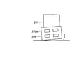
- the diameter of the tolerance ring 208 is expanded along the diameter of the pivot shaft 207 when the pivot shaft 207 reaches the formation position of the convex portion 208a.
- the present invention has been made in view of the above, and provides a tolerance ring, a hard disk device, and a method of manufacturing the hard disk device that can suppress the rotation of the carriage with respect to the pivot shaft and improve the assembly accuracy. Objective.
- the tolerance ring according to the present invention is formed using a plate-like member, forms a ring shape that substantially circulates along a predetermined direction, and projects in the radial direction.
- the tolerance ring provided with a plurality of convex portions, the outer edge side end portion in the direction orthogonal to the circumferential direction, the notch portion notched in the direction orthogonal to the circumferential direction from at least one outer edge side end portion It is characterized by having.
- the notch is provided between the plurality of protrusions, and a length in the circumferential direction is equal to or less than a distance between the plurality of protrusions. It is characterized by being.
- the notch has a length in a direction orthogonal to the circumferential direction from an outer edge side end in a direction orthogonal to the circumferential direction. It is more than the distance to the edge part of the said outer edge side edge part side, It is characterized by the above-mentioned.
- the tolerance ring according to the present invention is characterized in that, in the above invention, the notch is provided at a position that equally divides the circumferential side.
- the tolerance ring according to the present invention is characterized in that, in the above invention, the outer edge side end portion has one or two notches.
- the notch portion is provided on an extension portion extending from a base end, and on an end portion side different from the base end side of the extension portion. And an arcuate tip having a diameter of.
- the tolerance ring according to the present invention is characterized in that, in the above-mentioned invention, the diameter of the tip portion is a value equal to or larger than a circumferential width of the extending portion.
- the tolerance ring according to the present invention is characterized in that, in the above invention, the radius of curvature of the end portion in the circumferential direction is smaller than the radius of curvature of the portion other than the end portion in the circumferential direction.
- the tolerance ring according to the present invention is characterized in that, in the above invention, the radius of curvature continuously decreases in a direction from the portion other than the end portion toward the end portion.
- the plurality of convex portions are arranged along the circumferential direction, and are arranged in a row among the convex portions arranged along the circumferential direction.
- the number of the convex portions is a multiple of three.
- the hard disk device supports a hard disk as a recording medium, a magnetic head part for recording and reading information to and from the hard disk, and supports the magnetic head part, and rotates on the surface of the hard disk. It is formed using a carriage and a plate-like member, has a ring shape that circulates substantially along a predetermined direction, and is provided with a plurality of convex portions that project in the radial direction, and is accommodated in a hollow space formed in the carriage.
- a tolerance ring, and a pivot shaft inserted into the ring-shaped interior of the tolerance ring, wherein the tolerance ring is an outer edge side end in a direction orthogonal to the circumferential direction, and is at least one outer edge side. It has the notch part notched in the direction orthogonal to the said circumferential direction from an edge part, It is characterized by the above-mentioned.
- the method of manufacturing a hard disk device also includes a hollow space formed in a carriage that supports a magnetic head unit for recording and reading information on a hard disk as a recording medium and rotates on the surface of the hard disk.
- the pivot shaft is inserted into the tolerance ring, and the pivot shaft is formed into the convex portion. Even when the diameter of the end on the insertion side of the pivot shaft of the tolerance ring is increased, the end on the opposite side of the insertion side is prevented from floating up following this expansion. It is possible to suppress the rotation of the carriage with respect to the above and improve the assembly accuracy.
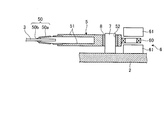
- FIG. 1 is a perspective view showing a schematic configuration of a hard disk device according to an embodiment of the present invention.
- FIG. 2 is a partial cross-sectional view showing a configuration of a main part of the hard disk device shown in FIG.
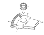
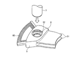
- FIG. 3 is a perspective view showing a configuration of a main part of the hard disk device shown in FIG.
- FIG. 4 is a perspective view showing a configuration of a main part of the hard disk device shown in FIG.
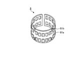
- FIG. 5 is a perspective view showing a configuration of a tolerance ring of the hard disk device shown in FIG.
- FIG. 6 is a top view showing a tolerance ring configuration of the hard disk device shown in FIG.
- FIG. 7 is a developed view schematically showing the configuration of the tolerance ring of the hard disk device shown in FIG. FIG.
- FIG. 8 is a schematic diagram showing the configuration of the tolerance ring of the hard disk device shown in FIG.
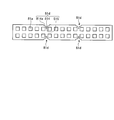
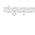
- FIG. 9 is a developed view schematically showing the configuration of the tolerance ring of the hard disk device according to the first modification of the embodiment of the present invention.
- FIG. 10 is a development view schematically showing the configuration of the tolerance ring of the hard disk device according to the second modification of the embodiment of the present invention.
- FIG. 11 is a developed view schematically showing the configuration of the tolerance ring of the hard disk device according to the third modification of the embodiment of the present invention.
- FIG. 12 is a developed view schematically showing the configuration of the tolerance ring of the hard disk device according to the fourth modification of the embodiment of the present invention.
- FIG. 13 is a developed view schematically showing the configuration of the tolerance ring of the hard disk device according to the fifth modification of the embodiment of the present invention.
- FIG. 14 is a graph showing the relationship between the notch depth and the inclination angle of the tolerance ring according to the embodiment of the present invention.
- FIG. 15 is a perspective view showing a schematic configuration of a conventional hard disk device.
- FIG. 16 is a side view showing a tolerance ring of a conventional hard disk device.
- FIG. 17 is a schematic diagram showing a configuration of a main part of a conventional hard disk device.
- FIG. 18 is a schematic diagram showing a configuration of a main part of a conventional hard disk device.
- FIG. 1 is a perspective view showing a schematic configuration of a hard disk device according to an embodiment of the present invention.
- the hard disk device 1 shown in FIG. 1 has a drive mechanism housed in a casing body 2.
- the drive mechanism supports a spindle 4 that rotationally drives a hard disk 3 that is a recording medium, a magnetic head unit 50 that records information on and reads information from the hard disk 3, and a carriage 5 that rotates on the surface of the hard disk 3;
- a VCM 6 that controls the scanning of the magnetic head unit 50 by precisely rotating the carriage 5 and a columnar pivot shaft 7 that is fixed to the casing body 2 and connects the casing body 2 and the carriage 5 are provided.
- the pivot shaft 7 has a substantially columnar shape, for example, and has a bearing configuration.
- FIG. 2 is a partial cross-sectional view showing a configuration of a main part of the hard disk device 1 shown in FIG. 3 and 4 are perspective views showing a configuration of a main part of the hard disk device 1 shown in FIG.
- the carriage 5 extends on the surface of the hard disk 3 and is connected to the arm 51 that holds the magnetic head unit 50 at the tip and the pivot shaft 7, and has a columnar hollow space whose cross section is slightly larger than the diameter of the cross section of the pivot shaft 7.
- a connecting part 52 having As shown in FIG. 2, the magnetic head unit 50 includes a suspension 50 a that floats with respect to the surface of the hard disk 3 by an air flow caused by the rotation of the hard disk 3, and an end of the suspension 50 a that is connected to the arm 51.
- a magnetic head 50b that is provided at an end portion on a different side and performs information recording and information reading.
- the carriage 5 has a plurality of magnetic head units 50 according to the number of hard disks 3.
- the VCM 6 includes a coil 60 connected to an end side different from the arm 51 side, and two magnets 61 sandwiching the coil 60.
- the VCM 6 drives the carriage 5 with a force generated by a current flowing through the coil 60 and a magnetic field. As a result, the carriage 5 is rotated on the surface of the hard disk 3 around the center of the pivot shaft 7 by the power from the VCM 6, and the magnetic head unit 50 is rotated on the surface of the hard disk 3.
- a tolerance ring 8 is used for fixing between the carriage 5 and the pivot shaft 7.
- the tolerance ring 8 is first accommodated in the hollow space of the connecting portion 52 of the carriage 5 (see FIGS. 3 and 4, accommodation step). Thereafter, the pivot shaft 7 is press-fitted into the tolerance ring 8 (see FIG. 4, insertion step), whereby the tolerance ring 8 is assembled between the carriage 5 and the pivot shaft 7. Fix between.
- the carriage 5 is fixed so as to be rotatable around the central axis in the longitudinal direction of the pivot shaft 7 which is a bearing.
- FIG. 5 is a perspective view showing the configuration of the tolerance ring 8.
- FIG. 6 is a top view showing the configuration of the tolerance ring 8, and is a view of the tolerance ring 8 shown in FIG. 5 as viewed from above.
- the tolerance ring 8 is formed using plate-shaped stainless steel, the circumferential direction is substantially ring-shaped, and the plurality of convex portions 81 a and the circumferential direction (and the plate thickness) from each edge.
- a cutout portion 81b cut out in a direction orthogonal to the direction).
- the convex portion 81 a protrudes in a substantially rectangular shape in the radial direction on the outer surface of the tolerance ring 8.
- the convex portions 81 a are provided in two rows along the circumferential direction of the tolerance ring 8. After the tolerance ring 8 is inserted into the opening on the carriage 5 side, the pivot shaft 7 is press-fitted into the tolerance ring 8. At this time, the convex portion 81 a is pressed against the inner wall surface of the connecting portion 52 of the carriage 5, and the carriage 5 and the pivot shaft 7 are fixed. Note that the length of the tolerance ring 8 in the circumferential direction is preferably equal to the length of the outer periphery of the opening of the connecting portion 52. Further, the protruding direction of the convex portion 81a may protrude toward the inner peripheral side along the radial direction.
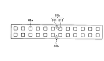
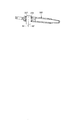
- FIG. 7 is a developed view schematically showing the configuration of the tolerance ring 8 of the hard disk device 1 shown in FIG. 1, and is a diagram in which the tolerance ring 8 is extended in the circumferential direction.
- FIG. 8 is a schematic diagram showing the configuration of the tolerance ring 8 of the hard disk device 1 shown in FIG.
- Two notches 81b are provided at both ends of the edge in the direction orthogonal to the circumferential direction of the tolerance ring 8, and are cut out from the ends in the direction orthogonal to the circumferential direction and the plate thickness direction.
- the notch 81b is provided at a position that divides the circumferential side into three equal parts.
- the notch 81b is provided on an extended portion 811 extending from the base end (the end in the direction orthogonal to the circumferential direction and the plate thickness direction), and on an end portion side different from the base end side of the extended portion 811.
- An arcuate tip 812 having a diameter (curvature radius).
- the distance d3 from the end in the direction orthogonal to the circumferential direction (and the plate thickness direction) of the tolerance ring 8 to the tip of the notch 81b is the edge of the tolerance ring 8 in the direction orthogonal to the circumferential direction and the plate thickness direction. It is a distance d4 or more from the part S (outer edge side end part) to the edge part S side end part of the convex part 81a.
- the tip 812 has an arc shape having a predetermined diameter. This diameter (diameter of curvature) is equivalent to the circumferential width (distance d1) of the extending portion 811.
- the tolerance ring 8 has an R-shaped tip 812 of the notch 81b, so that when the pivot shaft 7 is inserted into the tolerance ring 8 and the pivot shaft 7 reaches the convex portion 81a, the diameter of the end of the tolerance ring 8 is increased. Can be performed more flexibly. Thereby, it is possible to prevent the tolerance ring 8 from being broken due to stress concentration at the end due to the press-fitting of the pivot shaft 7.
- the length of the cutout (distance d3) is long, or when the number is large, the cutout portion is likely to be broken during assembly or cleaning. A small number is preferred.
- the tolerance ring 8 differs in the value of the curvature radius of the edge parts 82 and 83 in the circumferential direction and the curvature radius of parts other than the edge parts 82 and 83 in the circumferential direction as shown in the side view shown in FIG. Specifically, the radius of curvature of the end portions 82 and 83 in the circumferential direction is equal to the radius of curvature of the connecting portion 52 of the carriage 5. Further, the radius of curvature of the portions other than the end portions 82 and 83 in the circumferential direction is larger than the radius of curvature of the connecting portion 52 of the carriage 5. In FIG.
- a broken line P 0 indicates a circular shape with a radius of curvature of a portion other than the end portions 82 and 83 in the circumferential direction.
- each distance between the adjacent convex parts 81a is equal distance.
- the number of convex portions 81a arranged in a row is a multiple of three.
- the tolerance ring 8 includes the following method as an example of a manufacturing method.
- a progressive press that sequentially performs the above-described process on a base material extending in a strip shape is used.
- the base material extending in a flat plate shape is subjected to a contouring process by a press so that the contour (outer edge) of the tolerance ring 8 is formed, and a base material that forms the contour of the tolerance ring 8 is formed.
- the connected state of the base material and the base material is maintained by the runner.
- the molding process of the convex part 81a and the notch part 81b is performed with respect to the shape
- the convex part 81a and the notch part 81b are each shape
- the base material on which the convex portions 81a and the notches 81b are formed is subjected to a bending process.
- the base material is bent stepwise from both ends along the longitudinal direction of the main surface of the base material so that the convex portion 81a is on the outer surface side, and the curvatures of the end portions 82 and 83 in the circumferential direction are obtained.
- the radius is formed to be smaller than the radius of curvature of the portion other than the end portions 82 and 83 in the circumferential direction.
- the base material is curved so that the radius of curvature decreases continuously (in a multistage manner) in a direction from the portion other than the end portions 82 and 83 toward the end portions 82 and 83.
- the tolerance ring 8 can be obtained by cutting off the base material from the runner. Note that after the trimming process, the obtained tolerance ring 8 may be subjected to a process (setting process) for applying a stress greater than the maximum usable stress.
- the notch 81b that is notched in the direction orthogonal to the circumferential direction (and the plate thickness direction) of the tolerance ring 8 is provided. Even when the diameter of the end of the tolerance ring 8 on the insertion side of the pivot shaft 7 is increased when the pivot shaft 7 reaches the convex portion 81a, the insertion side follows the expansion. It is possible to prevent the end on the opposite side from floating and to suppress the rotation of the carriage with respect to the pivot shaft 7. As a result, the drive mechanism in the hard disk device 1 can be assembled accurately.
- the radius of curvature of the end portions 82 and 83 in the circumferential direction is equal to the radius of curvature of the connecting portion 52 of the carriage 5, and the radius of curvature of the portion other than the end portions 82 and 83 in the circumferential direction.
- the tolerance ring 8 is held inside the connecting portion 52 when inserted into the connecting portion 52 of the carriage 5, and the shape of the tolerance ring 8 in the circumferential direction is set.
- a circular shape along the wall surface of the connecting portion 52 can be used. For this reason, when the tolerance ring 8 is inserted into the connecting portion 52 of the carriage 5, it can be inserted without damaging the wall surface of the connecting portion 52. Therefore, the occurrence of contamination due to insertion of the tolerance ring can be suppressed.
- the conventional tolerance ring can be elastically deformed into a substantially circular shape along the circumferential direction, which is almost the same as the opening on the carriage side.
- the tolerance ring is held in the carriage during assembly work.
- the radius of curvature of the tolerance ring is designed to be larger than the radius of curvature of the carriage opening.
- the end side of the tolerance ring may be opened, and the radius of curvature of the end of the tolerance ring may be larger than the radius of curvature of the opening of the carriage.
- the tolerance ring 8 since the tolerance ring 8 according to the present embodiment has a circular shape along the wall surface of the connecting portion 52 in the circumferential direction, the wall surface of the connecting portion 52 is inserted into the connecting portion 52. Can be inserted without damage. Further, when the pivot shaft 7 is press-fitted, the pivot shaft 7 can be press-fitted without damaging the inner peripheral surface of the tolerance ring 8 and / or the side surface of the pivot shaft 7. Therefore, the occurrence of contamination due to the tolerance ring 8 can be suppressed.
- the tolerance ring 8 can easily press-fit the pivot shaft 7 into the tolerance ring 8, and the carriage 5 and the pivot 5 can be pressed by the press contact with the wall surface of the connecting portion 52 of the convex portion 81a.
- the space between the shaft 7 can be securely fixed.
- the shape of the convex part 81a of the tolerance ring 8 mentioned above demonstrated as what protruded in the substantially rectangular shape from the outer surface, if the shape satisfy
- the shape may be a substantially circular shape, or the outer edge shape of the protruding region from the outer surface may be a substantially circular shape.
- the convex part 81a was demonstrated as what is provided in two rows along the circumferential direction of the tolerance ring 8, it is not specified to this and may be provided in 1 row or multiple rows.
- the tolerance ring 8 described above has been described as being curved so that the radius of curvature decreases continuously (multi-stage) in the direction from the portion other than the end portion toward the end portions 82 and 83,
- the curvature radius of the part and the curvature radius of the part other than the end part may be curved in two stages.
- FIG. 9 is a developed view schematically showing the configuration of the tolerance ring of the hard disk device according to the first modification of the present embodiment, in which the tolerance ring is extended in the circumferential direction.
- the R-shaped diameter of the distal end portion 812 has been described as being equivalent to the circumferential width (distance d1) of the notch 81b.
- it may be a notch 81c having a tip 813 having a larger diameter (corresponding to the distance d1).
- FIG. 10 is a developed view schematically showing the configuration of the tolerance ring of the hard disk device according to the second modification of the present embodiment, in which the tolerance ring is extended in the circumferential direction.
- the extension portion 811 has been described as extending with the same width.
- the extension portion 814 having a reduced diameter portion 814a extending from the edge end portion.
- a notch portion 81d having an arcuate tip portion 815 that is provided on an end portion side different from the base end side of the extending portion 814 and has a predetermined diameter (curvature radius).
- the width of the reduced diameter portion 814a on the edge side is larger than the distance between the adjacent convex portions 81a.
- the extending portion 814 may have a stepped shape having a plurality of different widths, or may have a shape that continuously decreases in diameter. Further, the width on the edge end side of the reduced diameter portion 814a may be smaller than the distance between the convex portions 81a as long as the diameter decreases toward the tip end portion 815.
- FIG. 11 is a developed view schematically showing the configuration of the tolerance ring of the hard disk device according to the third modification of the present embodiment, in which the tolerance ring is extended in the circumferential direction.
- the extending portions 811 at both ends have been described as having the same length.
- the extending portions 811 are compared with the notches 81 b provided on one edge side.
- the notches 81e having different lengths of the extending portions may be provided on the other edge side.
- the notch 81e is provided on an extended portion 816 extending longer than the extended portion 811 from the edge end, and on an end portion side different from the edge end side of the extended portion 816, and has a predetermined diameter (curvature).
- the R-shaped diameter of the distal end portion 817 may be equal to the width of the extending portion 816 on the side continuous with the distal end portion 817, or may be larger than the circumferential width.
- FIG. 12 is a developed view schematically showing the configuration of the tolerance ring of the hard disk device according to the fourth modification of the present embodiment, in which the tolerance ring is extended in the circumferential direction.
- the notch portion 81b has been described as being provided at both edge end portions in the direction orthogonal to the circumferential direction of the notch portion 81b.
- the edge portion where the notch portion 81b is provided is an end portion of the tolerance ring 8 on the side different from the pivot shaft 7 insertion side.
- a notch portion is provided on one end side as in the tolerance ring according to the modified example 4, by providing the notch portion on the edge end portion on the side different from the pivot shaft 7 insertion side of the tolerance ring 8, The rotation suppression effect can be further increased.
- a notch portion having a length of 1.0 mm (corresponding to the distance d3) in the width direction (direction perpendicular to the circumferential direction) In contrast, when the notch portion of 1.0 mm is formed at one end (the end portion different from the pivot shaft 7 insertion side), the effect of suppressing the rotation of the carriage 5 can be further increased.
- FIG. 13 is a development view schematically showing the configuration of the tolerance ring of the hard disk device according to the fifth modification of the present embodiment, in which the tolerance ring is extended in the circumferential direction.
- the description will be made assuming that there are twelve convex portions 81a.
- the notch portion 81b has been described as being provided at a position that divides the circumferential side into three equal parts, but as shown in FIG. 13, a position that divides the circumferential side into two equal parts. It may be provided.
- a notch part is provided with two or more (3 or more) in the position which divides the edge
- FIG. 14 is a graph showing the relationship between the notch depth and the inclination angle of the tolerance ring according to this example.
- the depth of the notch (corresponding to the distance d3) is defined as the “notch depth”.
- the graph shown in FIG. 14 shows the relationship between the notch depth of the notch part and the inclination angle of the carriage axis (center axis of the hollow space of the connecting part 52) with respect to the center axis of the pivot axis.
- the inclination angle is obtained from the inclination of the carriage shaft after the pivot shaft is inserted into the tolerance ring.
- a stainless steel plate having a length of 4.0 mm, a width of 25.2 mm, and a thickness of 0.1 mm, and a tolerance ring having a substantially ring shape with the horizontal direction (longitudinal direction) being the circumferential direction was used.
- the tolerance ring according to the present embodiment has a convex portion (convex portion 81a) and a notch portion (notch portion 81b) shown in FIG.
- region R shown with a broken line in the graph of FIG. 14 has shown the formation area of the convex part 81a.
- the notch portion of the tolerance ring according to the present embodiment has a distance in the direction orthogonal to the circumferential direction and the plate thickness direction (notch width, see distance d1 in FIG. 8) of 0.1 mm, 0.3 mm, 0
- the angle of inclination was determined using each of .5 mm.
- the inclination angle is small. Further, the inclination angle becomes smaller as the notch width becomes longer as 0.1 mm, 0.3 mm, and 0.5 mm. Thereby, the inclination (rotation) of the axis of the tolerance ring with respect to the central axis of the pivot shaft can be suppressed by forming the notch portion, and the effect is further increased as the notch depth and the notch width are increased. be able to.
- the tolerance ring, the hard disk device, and the method for manufacturing the hard disk device according to the present invention are useful for suppressing the rotation of the carriage with respect to the pivot shaft when the pivot shaft is press-fitted and improving the assembly accuracy.
Landscapes
- Engineering & Computer Science (AREA)
- General Engineering & Computer Science (AREA)
- Mechanical Engineering (AREA)
- Moving Of Heads (AREA)
- Support Of The Bearing (AREA)
- Mounting Of Bearings Or Others (AREA)
- Rolling Contact Bearings (AREA)
Abstract
Description
2,201 ケーシング本体
3,202 ハードディスク
4,203 スピンドル
5,205 キャリッジ
6,206 VCM
7,207 ピボット軸
8,208 トレランスリング
50 磁気ヘッド部
50a サスペンション
50b,204 磁気ヘッド
51 アーム
52 連結部
60 コイル
61 磁石
81a,208a 凸部
81b,81c,81d,81e 切欠部
82,83 端部
811,814,816 延在部
812,813,815,817 先端部
Claims (12)
- 板状の部材を用いて形成され、所定方向に沿って略周回するリング状をなし、径方向に突出する複数の凸部が設けられたトレランスリングにおいて、
周方向と直交する方向の外縁側端部であって、少なくとも一方の外縁側端部から、前記周方向と直交する方向に切り欠かれた切欠部を有することを特徴とするトレランスリング。 - 前記切欠部は、前記複数の凸部の間に設けられ、
前記周方向の長さが、前記複数の凸部の間の距離以下であることを特徴とする請求項1に記載のトレランスリング。 - 前記切欠部は、前記周方向と直交する方向の長さが、前記周方向と直交する方向の外縁側端部から、前記凸部の前記外縁側端部側の端部までの距離以上であることを特徴とする請求項2に記載のトレランスリング。
- 前記切欠部は、前記周方向の辺を等分する位置に設けられることを特徴とする請求項1~3のいずれか一つに記載のトレランスリング。
- 前記外縁側端部に、1つまたは2つの前記切欠部を有することを特徴とする請求項1~4のいずれか一つに記載のトレランスリング。
- 前記切欠部は、
基端から延びる延在部と、
前記延在部の前記基端側と異なる側の端部側に設けられ、所定の径を有する弧状をなす先端部と、
を有することを特徴とする請求項1~5のいずれか一つに記載のトレランスリング。 - 前記先端部の径は、前記延在部における周方向の幅以上の値であることを特徴とする請求項6に記載のトレランスリング。
- 周方向における端部の曲率半径が、前記周方向における前記端部以外の部分の曲率半径より小さいことを特徴とする請求項1~7のいずれか一つに記載のトレランスリング。
- 前記端部以外の部分から前記端部に向かう方向に従って連続的に曲率半径が小さくなることを特徴とする請求項8に記載のトレランスリング。
- 前記複数の凸部は、前記周方向に沿って配置され、
前記周方向に沿って配置される前記凸部のうち、一列に配置される前記凸部の個数は、3の倍数であることを特徴とする請求項1~9のいずれか一つに記載のトレランスリング。 - 記録メディアであるハードディスクと、
前記ハードディスクへの情報記録および情報読み出しを行う磁気ヘッド部と、
前記磁気ヘッド部を支持し、前記ハードディスクの面上を回動するキャリッジと、
板状の部材を用いて形成され、所定方向に沿って略周回するリング状をなし、径方向に突出する複数の凸部が設けられ、前記キャリッジに形成された中空空間に収容されるトレランスリングと、
前記トレランスリングの前記リング状の内部に挿入されるピボット軸と、
を備え、
前記トレランスリングは、周方向と直交する方向の外縁側端部であって、少なくとも一方の外縁側端部から、前記周方向と直交する方向に切り欠かれた切欠部を有することを特徴とするハードディスク装置。 - 記録メディアであるハードディスクへの情報記録および情報読み出しを行う磁気ヘッド部を支持し、前記ハードディスクの面上を回動するキャリッジに形成された中空空間に、板状の部材を用いて形成され、所定方向に沿って略周回するリング状をなし、径方向に突出する複数の凸部が設けられたトレランスリングを収容する収容ステップと、
前記トレランスリングの前記リング状の内部にピボット軸を挿入する挿入ステップと、
を含み、
前記トレランスリングは、周方向と直交する方向の外縁側端部であって、少なくとも一方の外縁側端部から、前記周方向と直交する方向に切り欠かれた切欠部を有することを特徴とするハードディスク装置の製造方法。
Priority Applications (3)
| Application Number | Priority Date | Filing Date | Title |
|---|---|---|---|
| CN201280060681.XA CN103975390B (zh) | 2011-12-09 | 2012-12-10 | 公差环、硬盘装置及硬盘装置的制造方法 |
| US14/362,742 US9255609B2 (en) | 2011-12-09 | 2012-12-10 | Tolerance ring, hard disk device, and method for manufacturing hard disk device |
| JP2013548326A JP5781628B2 (ja) | 2011-12-09 | 2012-12-10 | トレランスリング、ハードディスク装置およびハードディスク装置の製造方法 |
Applications Claiming Priority (2)
| Application Number | Priority Date | Filing Date | Title |
|---|---|---|---|
| JP2011-270726 | 2011-12-09 | ||
| JP2011270726 | 2011-12-09 |
Publications (1)
| Publication Number | Publication Date |
|---|---|
| WO2013085060A1 true WO2013085060A1 (ja) | 2013-06-13 |
Family
ID=48574409
Family Applications (1)
| Application Number | Title | Priority Date | Filing Date |
|---|---|---|---|
| PCT/JP2012/081987 Ceased WO2013085060A1 (ja) | 2011-12-09 | 2012-12-10 | トレランスリング、ハードディスク装置およびハードディスク装置の製造方法 |
Country Status (4)
| Country | Link |
|---|---|
| US (1) | US9255609B2 (ja) |
| JP (1) | JP5781628B2 (ja) |
| CN (1) | CN103975390B (ja) |
| WO (1) | WO2013085060A1 (ja) |
Cited By (1)
| Publication number | Priority date | Publication date | Assignee | Title |
|---|---|---|---|---|
| JPWO2015080276A1 (ja) * | 2013-11-29 | 2017-03-16 | 日本発條株式会社 | トレランスリングおよびハードディスク装置 |
Families Citing this family (5)
| Publication number | Priority date | Publication date | Assignee | Title |
|---|---|---|---|---|
| US20160252119A1 (en) * | 2015-02-27 | 2016-09-01 | Foremost Industries Lp | Serrated shaft-engaging surface for shrink disc |
| US9908167B1 (en) | 2015-03-02 | 2018-03-06 | Western Digital Technologies, Inc. | Disk drive tolerance ring with edge rounding from opposite major faces |
| JP6605253B2 (ja) * | 2015-08-07 | 2019-11-13 | 株式会社東郷製作所 | トレランスリング |
| WO2019063752A2 (en) * | 2017-09-29 | 2019-04-04 | Saint-Gobain Performance Plastics Rencol Limited | Tolerance ring |
| US11137032B1 (en) * | 2020-05-29 | 2021-10-05 | Bell Textron Inc. | Ceramic bearing system |
Citations (5)
| Publication number | Priority date | Publication date | Assignee | Title |
|---|---|---|---|---|
| JP2002106554A (ja) * | 2000-10-04 | 2002-04-10 | Minebea Co Ltd | ピボット軸受装置 |
| JP2002130266A (ja) * | 2000-08-30 | 2002-05-09 | Skf France | 軸受装置 |
| JP2003518592A (ja) * | 1999-12-03 | 2003-06-10 | シーゲイト テクノロジー エルエルシー | 一貫した取付け力プロファイルが低いトレランス・リング |
| US7850389B2 (en) * | 2006-08-15 | 2010-12-14 | Intriplex Technologies, Inc. | Tolerance ring having various end tab designs to prevent interlocking |
| JP2012052638A (ja) * | 2010-09-03 | 2012-03-15 | Togo Seisakusho Corp | トルク伝達装置用トレランスリング |
Family Cites Families (16)
| Publication number | Priority date | Publication date | Assignee | Title |
|---|---|---|---|---|
| US4981390A (en) * | 1987-03-06 | 1991-01-01 | The Ray Engineering Co., Ltd. | Tolerance ring with retaining means |
| US5315465A (en) | 1991-07-12 | 1994-05-24 | Seagate Technology, Inc. | Compliant pivot mechanism for a rotary actuator |
| CN1433509A (zh) | 2000-02-09 | 2003-07-30 | 西加特技术有限责任公司 | 具有高的箍强度以抵制变形的公差配合环 |
| JP2002130310A (ja) | 2000-10-20 | 2002-05-09 | Nsk Ltd | ユニット軸受 |
| GB0425856D0 (en) | 2004-11-24 | 2004-12-29 | Rencol Tolerance Rings Ltd | Fixing of components |
| JP2007305268A (ja) | 2006-05-15 | 2007-11-22 | Nsk Ltd | 軸受ユニット |
| US7583476B2 (en) * | 2006-08-22 | 2009-09-01 | Intri-Plex Technologies, Inc. | Tolerance ring for data storage with cut-out feature for mass control |
| ES2385025T3 (es) * | 2006-09-07 | 2012-07-17 | Saint-Gobain Performance Plastics Rencol Limited | Anillo de montaje de combinación |
| US8684624B2 (en) | 2008-07-01 | 2014-04-01 | Saint-Gobain Performance Plastics Rencol Limited | Tolerance ring |
| US8157450B2 (en) * | 2008-08-22 | 2012-04-17 | Baldor Electric Company | Waveform expansion sleeve for a bearing |
| US20110076096A1 (en) * | 2009-09-25 | 2011-03-31 | Saint-Gobain Performance Plastics Rencol Limited | System, method and apparatus for tolerance ring control of slip interface sliding forces |
| US8385024B2 (en) * | 2010-10-07 | 2013-02-26 | IntriPlex Technologies | Tolerance ring with edge bump difference |
| US9019663B2 (en) * | 2011-12-28 | 2015-04-28 | Nhk Spring Co., Ltd. | Tolerance ring |
| KR101635729B1 (ko) * | 2012-04-30 | 2016-07-05 | 생-고뱅 퍼포먼스 플라스틱스 렌콜 리미티드 | 슬롯형 측벽을 가지는 공차링 |
| US9062700B2 (en) * | 2012-06-29 | 2015-06-23 | Saint-Gobain Performance Plastics Rencol Limited | Tolerance ring with component engagement structures |
| EP2938896B1 (en) * | 2012-12-31 | 2021-06-16 | Saint-Gobain Performance Plastics Rencol Limited | Tolerance ring with discrete tolerance ring panels |
-
2012
- 2012-12-10 US US14/362,742 patent/US9255609B2/en not_active Expired - Fee Related
- 2012-12-10 WO PCT/JP2012/081987 patent/WO2013085060A1/ja not_active Ceased
- 2012-12-10 CN CN201280060681.XA patent/CN103975390B/zh not_active Expired - Fee Related
- 2012-12-10 JP JP2013548326A patent/JP5781628B2/ja active Active
Patent Citations (5)
| Publication number | Priority date | Publication date | Assignee | Title |
|---|---|---|---|---|
| JP2003518592A (ja) * | 1999-12-03 | 2003-06-10 | シーゲイト テクノロジー エルエルシー | 一貫した取付け力プロファイルが低いトレランス・リング |
| JP2002130266A (ja) * | 2000-08-30 | 2002-05-09 | Skf France | 軸受装置 |
| JP2002106554A (ja) * | 2000-10-04 | 2002-04-10 | Minebea Co Ltd | ピボット軸受装置 |
| US7850389B2 (en) * | 2006-08-15 | 2010-12-14 | Intriplex Technologies, Inc. | Tolerance ring having various end tab designs to prevent interlocking |
| JP2012052638A (ja) * | 2010-09-03 | 2012-03-15 | Togo Seisakusho Corp | トルク伝達装置用トレランスリング |
Cited By (1)
| Publication number | Priority date | Publication date | Assignee | Title |
|---|---|---|---|---|
| JPWO2015080276A1 (ja) * | 2013-11-29 | 2017-03-16 | 日本発條株式会社 | トレランスリングおよびハードディスク装置 |
Also Published As
| Publication number | Publication date |
|---|---|
| US20140362474A1 (en) | 2014-12-11 |
| CN103975390A (zh) | 2014-08-06 |
| CN103975390B (zh) | 2017-05-24 |
| US9255609B2 (en) | 2016-02-09 |
| JP5781628B2 (ja) | 2015-09-24 |
| JPWO2013085060A1 (ja) | 2015-04-27 |
Similar Documents
| Publication | Publication Date | Title |
|---|---|---|
| JP6040167B2 (ja) | トレランスリング | |
| JP5781628B2 (ja) | トレランスリング、ハードディスク装置およびハードディスク装置の製造方法 | |
| JP5787987B2 (ja) | トレランスリングおよびトレランスリングの製造方法 | |
| KR20020060765A (ko) | 일정한 작은 설치력 프로파일을 가지는 공차 링 | |
| JP6047106B2 (ja) | トレランスリングおよびハードディスク装置の製造方法 | |
| JP6424171B2 (ja) | トレランスリングおよびハードディスク装置 | |
| JPWO2013172313A1 (ja) | トレランスリング | |
| JP2012165541A (ja) | モータおよび記録ディスク駆動装置 | |
| JP2007236146A (ja) | スピンドルモータ及びその製造方法 | |
| JPWO2014123166A1 (ja) | トレランスリングおよびハードディスク装置 | |
| JP2012189182A (ja) | 転がり軸受、軸受装置及び情報記録再生装置 | |
| JP5211365B2 (ja) | モーター | |
| JP2008312301A (ja) | スピンドルモータ及びその製造方法 | |
| JP2001052401A (ja) | ディスク用調心装置およびこれを備えるディスク駆動用モータ | |
| US9908167B1 (en) | Disk drive tolerance ring with edge rounding from opposite major faces | |
| JP6272377B2 (ja) | ディスク回転用モータおよびこれを備えたディスク駆動装置 | |
| KR101070042B1 (ko) | 모터 장치 및 상기 모터 장치를 제조하는 제조 방법 | |
| JP2010170631A (ja) | チャッキング装置、ブラシレスモータ、及びディスク駆動装置 | |
| JP2013090465A (ja) | ディスク回転用モータおよびこれを備えたディスク駆動装置 | |
| JP2004139689A (ja) | モータおよびモータを有する情報記録再生装置 | |
| JP2007265537A (ja) | ディスク回転駆動装置及びそのディスク取付方法、スプリング・ワッシャ | |
| JP2008305460A (ja) | ターンテーブル |
Legal Events
| Date | Code | Title | Description |
|---|---|---|---|
| 121 | Ep: the epo has been informed by wipo that ep was designated in this application |
Ref document number: 12855739 Country of ref document: EP Kind code of ref document: A1 |
|
| ENP | Entry into the national phase |
Ref document number: 2013548326 Country of ref document: JP Kind code of ref document: A |
|
| WWE | Wipo information: entry into national phase |
Ref document number: 14362742 Country of ref document: US |
|
| NENP | Non-entry into the national phase |
Ref country code: DE |
|
| 122 | Ep: pct application non-entry in european phase |
Ref document number: 12855739 Country of ref document: EP Kind code of ref document: A1 |