WO2013084958A1 - 電子機器及び振動音減衰方法 - Google Patents
電子機器及び振動音減衰方法 Download PDFInfo
- Publication number
- WO2013084958A1 WO2013084958A1 PCT/JP2012/081558 JP2012081558W WO2013084958A1 WO 2013084958 A1 WO2013084958 A1 WO 2013084958A1 JP 2012081558 W JP2012081558 W JP 2012081558W WO 2013084958 A1 WO2013084958 A1 WO 2013084958A1
- Authority
- WO
- WIPO (PCT)
- Prior art keywords
- sound
- vibration
- unit
- electronic device
- antiphase
- Prior art date
- Legal status (The legal status is an assumption and is not a legal conclusion. Google has not performed a legal analysis and makes no representation as to the accuracy of the status listed.)
- Ceased
Links
Images


Classifications
-
- H—ELECTRICITY
- H04—ELECTRIC COMMUNICATION TECHNIQUE
- H04M—TELEPHONIC COMMUNICATION
- H04M19/00—Current supply arrangements for telephone systems
- H04M19/02—Current supply arrangements for telephone systems providing ringing current or supervisory tones, e.g. dialling tone or busy tone
- H04M19/04—Current supply arrangements for telephone systems providing ringing current or supervisory tones, e.g. dialling tone or busy tone the ringing-current being generated at the substations
- H04M19/047—Vibrating means for incoming calls
-
- G—PHYSICS
- G10—MUSICAL INSTRUMENTS; ACOUSTICS
- G10K—SOUND-PRODUCING DEVICES; METHODS OR DEVICES FOR PROTECTING AGAINST, OR FOR DAMPING, NOISE OR OTHER ACOUSTIC WAVES IN GENERAL; ACOUSTICS NOT OTHERWISE PROVIDED FOR
- G10K11/00—Methods or devices for transmitting, conducting or directing sound in general; Methods or devices for protecting against, or for damping, noise or other acoustic waves in general
- G10K11/16—Methods or devices for protecting against, or for damping, noise or other acoustic waves in general
- G10K11/175—Methods or devices for protecting against, or for damping, noise or other acoustic waves in general using interference effects; Masking sound
- G10K11/178—Methods or devices for protecting against, or for damping, noise or other acoustic waves in general using interference effects; Masking sound by electro-acoustically regenerating the original acoustic waves in anti-phase
- G10K11/1781—Methods or devices for protecting against, or for damping, noise or other acoustic waves in general using interference effects; Masking sound by electro-acoustically regenerating the original acoustic waves in anti-phase characterised by the analysis of input or output signals, e.g. frequency range, modes, transfer functions
- G10K11/17821—Methods or devices for protecting against, or for damping, noise or other acoustic waves in general using interference effects; Masking sound by electro-acoustically regenerating the original acoustic waves in anti-phase characterised by the analysis of input or output signals, e.g. frequency range, modes, transfer functions characterised by the analysis of the input signals only
- G10K11/17823—Reference signals, e.g. ambient acoustic environment
-
- G—PHYSICS
- G10—MUSICAL INSTRUMENTS; ACOUSTICS
- G10K—SOUND-PRODUCING DEVICES; METHODS OR DEVICES FOR PROTECTING AGAINST, OR FOR DAMPING, NOISE OR OTHER ACOUSTIC WAVES IN GENERAL; ACOUSTICS NOT OTHERWISE PROVIDED FOR
- G10K11/00—Methods or devices for transmitting, conducting or directing sound in general; Methods or devices for protecting against, or for damping, noise or other acoustic waves in general
- G10K11/16—Methods or devices for protecting against, or for damping, noise or other acoustic waves in general
- G10K11/175—Methods or devices for protecting against, or for damping, noise or other acoustic waves in general using interference effects; Masking sound
- G10K11/178—Methods or devices for protecting against, or for damping, noise or other acoustic waves in general using interference effects; Masking sound by electro-acoustically regenerating the original acoustic waves in anti-phase
- G10K11/1787—General system configurations
- G10K11/17873—General system configurations using a reference signal without an error signal, e.g. pure feedforward
-
- G—PHYSICS
- G10—MUSICAL INSTRUMENTS; ACOUSTICS
- G10K—SOUND-PRODUCING DEVICES; METHODS OR DEVICES FOR PROTECTING AGAINST, OR FOR DAMPING, NOISE OR OTHER ACOUSTIC WAVES IN GENERAL; ACOUSTICS NOT OTHERWISE PROVIDED FOR
- G10K11/00—Methods or devices for transmitting, conducting or directing sound in general; Methods or devices for protecting against, or for damping, noise or other acoustic waves in general
- G10K11/16—Methods or devices for protecting against, or for damping, noise or other acoustic waves in general
- G10K11/175—Methods or devices for protecting against, or for damping, noise or other acoustic waves in general using interference effects; Masking sound
- G10K11/178—Methods or devices for protecting against, or for damping, noise or other acoustic waves in general using interference effects; Masking sound by electro-acoustically regenerating the original acoustic waves in anti-phase
- G10K11/1787—General system configurations
- G10K11/17885—General system configurations additionally using a desired external signal, e.g. pass-through audio such as music or speech
-
- H—ELECTRICITY
- H04—ELECTRIC COMMUNICATION TECHNIQUE
- H04R—LOUDSPEAKERS, MICROPHONES, GRAMOPHONE PICK-UPS OR LIKE ACOUSTIC ELECTROMECHANICAL TRANSDUCERS; ELECTRIC HEARING AIDS; PUBLIC ADDRESS SYSTEMS
- H04R3/00—Circuits for transducers
- H04R3/12—Circuits for transducers for distributing signals to two or more loudspeakers
-
- G—PHYSICS
- G10—MUSICAL INSTRUMENTS; ACOUSTICS
- G10K—SOUND-PRODUCING DEVICES; METHODS OR DEVICES FOR PROTECTING AGAINST, OR FOR DAMPING, NOISE OR OTHER ACOUSTIC WAVES IN GENERAL; ACOUSTICS NOT OTHERWISE PROVIDED FOR
- G10K2210/00—Details of active noise control [ANC] covered by G10K11/178 but not provided for in any of its subgroups
- G10K2210/10—Applications
- G10K2210/108—Communication systems, e.g. where useful sound is kept and noise is cancelled
-
- H—ELECTRICITY
- H04—ELECTRIC COMMUNICATION TECHNIQUE
- H04R—LOUDSPEAKERS, MICROPHONES, GRAMOPHONE PICK-UPS OR LIKE ACOUSTIC ELECTROMECHANICAL TRANSDUCERS; ELECTRIC HEARING AIDS; PUBLIC ADDRESS SYSTEMS
- H04R2499/00—Aspects covered by H04R or H04S not otherwise provided for in their subgroups
- H04R2499/10—General applications
- H04R2499/11—Transducers incorporated or for use in hand-held devices, e.g. mobile phones, PDA's, camera's
Definitions
- the present invention relates to an electronic device and a vibration sound attenuation method.
- This application claims priority based on Japanese Patent Application No. 2011-266836 filed on Dec. 6, 2011, the contents of which are incorporated herein by reference.
- Patent Document 1 is known as an electronic device such as a mobile phone or a portable information terminal.
- a configuration that allows a user to detect vibration may be used.
- An object of the present invention is to provide an electronic device and a vibration sound attenuation method that can attenuate vibration sound generated by vibration of the electronic device.
- An electronic apparatus includes a vibration unit that generates vibration, an anti-phase sound that is in reverse phase with respect to a noise sound due to the vibration, and a sound output unit that outputs sound toward the user. And a control unit for outputting the sound directed to the user from the sound output unit while outputting the antiphase sound from the sound output unit as the vibration unit is vibrated.
- FIG. 1 is a block diagram illustrating a functional configuration of the electronic device 100 according to the present embodiment.
- the electronic device 100 includes a control unit 111, a storage unit 112, a built-in microphone 113, a built-in speaker 114, a display unit 10, a vibration unit 16, an operation unit 115, and an external speaker 24.
- the vibration unit 16 includes a voice coil motor and the like, and generates vibration.
- the built-in microphone (sound collecting unit) 113 is installed in the housing of the electronic device 100 and collects vibration sound of vibration generated by the vibration unit 16.
- the vibration sound is a sound generated by vibration.
- the built-in speaker (first speaker) 114 is installed in the housing of the electronic device 100 and outputs sound for attenuating the vibration sound of the vibration generated by the vibration unit 16.
- the external speaker (second speaker) 24 is a speaker that outputs sound to the outside of the electronic device 100, and outputs sound directed to the user, such as music or notification sound.
- the display unit 10 is, for example, a liquid crystal display panel or an organic EL panel, and displays an image or the like. Note that a touch panel mechanism (not shown) may be provided on the display surface of the display unit 10.
- the operation unit 115 receives an operation from the user.
- the operation unit 115 has a detection unit installed on a side surface with respect to a surface on which the display surface of the display unit 10 is installed. A detection part detects the presence or absence and contact position of a contact.
- the storage unit 112 stores audio data corresponding to the vibration generated by the vibration unit 16 and the contact position detected by the detection unit included in the operation unit 115.
- the sound data is sound data having an opposite phase to the vibration sound collected in advance by experiments or the like.
- the control unit 111 controls each unit of the electronic device 100 in an integrated manner. For example, the control unit 111 detects the contact position detected by the detection unit of the operation unit 115 and the vibration unit when the vibration unit 16 is vibrated only when the detection unit of the operation unit 115 detects contact.
- the sound data of the vibration sound corresponding to the vibration generated in 16 is read from the storage unit 112, and the vibration based on the read sound data is output to the built-in speaker 114 at the same time as the vibration unit 16 is vibrated. That is, the control unit 111 outputs a sound based on the sound data read from the built-in speaker 114 in synchronization with the vibration in the vibration unit 16.
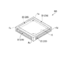
- FIG. 2 is a perspective view illustrating an external configuration of the electronic apparatus 100 according to the present embodiment.
- the housing of the electronic device 100 holds the display unit 10 and the detection unit 22 included in the operation unit 115.
- the display unit 10 is provided on the plate surface of the housing.
- a surface on which the display unit 10 is provided in the housing is hereinafter referred to as a display surface.
- the operation unit 115 includes detection units 22A to 22D provided on four side surfaces Fa to Fd corresponding to the four sides surrounding the display surface of the housing.
- the detection unit 22A is provided on the side surface Fa
- the detection unit 22B is provided on the side surface Fb
- the detection unit 22C is provided on the side surface Fc
- the detection unit 22D is provided on the side surface Fd.
- the detection units 22A to 22D detect the presence / absence and contact position of an external (for example, user) contact on each of the side surfaces Fa to Fd.
- the symbols A to D are omitted, and are simply referred to as “detection unit 22” or “each detection unit 22”.
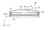
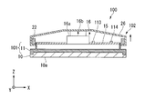
- FIGS. 3 and 4 are views showing a cross-sectional configuration of the electronic apparatus 100 according to the present embodiment.
- the electronic device 100 includes a display unit 10, a base unit 11, a bottom cover 15, a vibration unit 16, a detection unit 22, a cover member 26, a built-in microphone 113, and a built-in speaker 114. Yes.
- the electronic device 100 is assembled in a state where these components are stacked. Note that power supplies such as a control unit and a battery are not shown in the figure.
- an XYZ orthogonal coordinate system is used to describe the configuration of the electronic device 100.
- the stacking direction of the components of the electronic device 100 is the Z direction.
- a plane orthogonal to the Z direction is defined as an XY plane, and directions orthogonal to the XY plane are defined as an X direction and a Y direction, respectively.
- the display unit 10 is formed in a rectangular shape when viewed in the Z direction.
- the display unit 10 has a ⁇ Z side surface as a display surface 10a.
- the base unit 11 holds the display unit 10.
- the base part 11 is formed so as to surround the side part of the display part 10 and the peripheral part of the display surface 10a.
- the base portion 11 is a first housing portion 101 for accommodating an electronic circuit.
- the vibration part 16 has a fixed part 16a, a movable part 16b, and a drive part.
- the fixed part 16a is formed in a cylindrical shape, for example, and accommodates the movable part 16b and the drive part.
- the fixed portion 16 a is disposed in the opening of the bottom cover 15.
- the movable part 16b is provided so as to be movable in the Z direction.
- the drive unit is connected to the movable unit 16b and moves the movable unit 16b in the Z direction.
- a voice coil motor is used as the drive unit.
- the drive operation of the drive unit is performed by a control circuit (control unit 111).
- the vibration unit 16 has a configuration in which the movable unit 16b vibrates in the Z direction when the drive unit reciprocates the movable unit 16b in the Z direction.
- the cover member 26 covers the + Z side end of the electronic device 100.
- the cover member 26 has a detection unit 22.
- the cover member 26 and the detection unit 22 serve as a second housing portion 102 for housing an electronic circuit.
- the second housing portion 102 and the first housing portion 101 including the base portion 11 constitute a housing of the electronic device 100.
- the built-in microphone 113 is installed in the second casing portion 102 and in the vicinity of the vibration unit 16.
- the built-in speaker 114 is installed in a position different from the built-in microphone 113 in the second housing portion 102.
- the cover member 26 is connected to the movable part 16b of the vibration part 16. Therefore, the cover member 26 is provided so as to be movable in the Z direction integrally with the movable portion 16b.
- the vibration of the movable portion 16b is transmitted to the cover member 26, and the cover member 26 vibrates in the Z direction.
- the cover member 26 and the detection part 22 move in the + Z direction as the movable part 16b moves, as shown in FIG. Accordingly, the space between the first housing portion 101 and the second housing portion 102 is widened, and the relative movement between the first housing portion 101 and the second housing portion 102 has been performed. become.
- the cover member 26 moves in the ⁇ Z direction as the movable portion 16b moves, and returns to the state shown in FIG. Also in this case, a relative movement has been performed between the first housing portion 101 and the second housing portion 102. In the case of this embodiment, the cover member 26 and the detection unit 22 vibrate by reciprocating (vibrating) the movable part 16b in the Z direction.
- the electronic device 100 includes a housing having the first housing portion 101 and the second housing portion 102 for housing the electronic circuit, and the first housing portion 101 and the second housing that vibrate in a predetermined direction. Since the vibration unit 16 that relatively moves the housing portion 102 is provided, at least one of the first housing portion 101 and the second housing portion 102 can be directly vibrated. As a result, vibration can be efficiently transmitted to the outside.
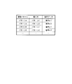
- FIG. 5 is a schematic diagram illustrating a data structure and a data example of a voice table stored in the storage unit 112 according to the present embodiment.
- the voice table is a two-dimensional tabular data composed of rows and columns, and has a column for each item of vibration pattern, grip method, and voice data. Each row of this table exists for each set of vibration pattern and contact position.
- the vibration pattern is a pattern of vibration generated by the vibration unit 16 and is, for example, a combination of vibration frequency, phase, vibration amplitude, or the like.
- the gripping method is a gripping method for the user to hold the electronic device 100, and is a contact position detected by the detection units 22A to 22D of the operation unit 115 when the user grips the electronic device 100.
- the contact position detected by the detection units 22A to 22D when the user holds the electronic device 100 is stored in the gripping item.
- the contact positions of two patterns (pattern 1 and pattern 2) corresponding to how the electronic device 100 is gripped are stored.
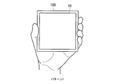
- the grip position “pattern 1” stores the contact position when the left and right side surfaces are gripped as shown in FIG. 6A.
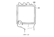
- the gripping method “pattern 2” stores the contact position when the upper and lower side surfaces are gripped as shown in FIG. 6B.
- the audio data is audio data having an opposite phase to the vibration sound caused by the vibration generated by the vibration unit 16.
- the audio data includes vibration sound that is generated when the electronic device 100 vibrates in a vibration pattern when the detection units 22A to 22D detect contact at the contact position stored in the grip method item, Audio data having a phase opposite to that of the vibration sound whose volume is larger than the predetermined threshold value ⁇ is stored.
- This vibration sound is collected in advance by experiments or the like.
- the threshold ⁇ is, for example, a volume at which a human ear can be heard.
- FIG. 7 is a flowchart showing the procedure of the vibration sound attenuation process according to the present embodiment.
- the control unit 111 performs the vibration sound attenuation process when the vibration unit 16 generates vibration. At this time, the vibration pattern of the vibration generated in the vibration unit 16 has already been determined.
- the control unit 111 determines whether or not the detection units 22A to 22D detect contact (step S101).
- step S101 Yes
- step S102 the control unit 111 causes the built-in speaker 114 to output sound based on the sound data read from the sound table at the same time as vibrating the vibration unit 16 with the vibration pattern. That is, the control unit 111 synchronizes the vibration of the vibration unit 16 and the sound output from the built-in speaker 114. Thereby, the vibration sound due to the vibration is attenuated by the sound output from the built-in speaker 114.
- the control unit 111 determines whether or not a predetermined time has elapsed since the internal speaker 114 output sound (step S104). If the predetermined time has not elapsed (step S104: No), the control unit 111 returns to step S104. On the other hand, when a predetermined time has elapsed (step S104: Yes), the control unit 111 corrects the sound output from the built-in speaker 114 based on the sound collected by the built-in microphone 113. Specifically, the control unit 111 reads the sound collected in the built-in microphone 113 in a step S102 that is in a phase opposite to the collected sound when the volume of the sound collected by the built-in microphone 113 is larger than a predetermined threshold value ⁇ . When the difference from the sound is equal to or greater than a predetermined threshold, the sound with the opposite phase to the sound collected by the built-in microphone 113 is output by the built-in speaker 114.
- the electronic device 100 stores the sound data in the opposite phase to the vibration sound corresponding to the vibration pattern and the gripping method in the sound table in advance, and generates the vibration.
- a sound based on the sound data read from the sound table is output from the built-in speaker 114.
- the vibration sound can be attenuated by the sound output from the built-in speaker 114.
- the processing load is reduced as compared with the case where the built-in microphone 113 collects the vibration sound.
- the processing time is shortened, and the time lag between the generation of vibration sound and the sound output by the built-in speaker 114 is reduced.
- the sound output from the built-in speaker 114 is corrected based on the vibration sound collected by the built-in microphone 113 after a predetermined time has elapsed, the vibration sound can be attenuated with higher accuracy.
- a program for realizing each step shown in FIG. 7 is recorded on a computer-readable recording medium, and the program recorded on the recording medium is read and executed by a computer system, thereby performing image display processing.
- the “computer system” may include an OS and hardware such as peripheral devices.
- “Computer-readable recording medium” means a floppy (registered trademark) disk, a magneto-optical disk, an SD card, a writable non-volatile memory such as a flash memory, a portable medium such as a CD-ROM, and a computer system.
- a built-in storage device such as a hard disk.
- the “computer-readable recording medium” refers to a volatile memory (for example, DRAM (Dynamic DRAM)) in a computer system that becomes a server or a client when a program is transmitted via a network such as the Internet or a communication line such as a telephone line. Random Access Memory)), etc., which hold programs for a certain period of time.
- the program may be transmitted from a computer system storing the program in a storage device or the like to another computer system via a transmission medium or by a transmission wave in the transmission medium.
- the “transmission medium” for transmitting the program refers to a medium having a function of transmitting information, such as a network (communication network) such as the Internet or a communication line (communication line) such as a telephone line.
- the program may be for realizing a part of the functions described above. Furthermore, what can implement
- the configuration in which one vibration part is arranged has been described as an example.
- the present invention is not limited to this.
- a configuration in which a plurality of vibration units are arranged may be used.
- the vibration part can be provided at a plurality of different positions.
- the configuration may be such that one vibration unit 16 is arranged at each of four corners of the electronic device 100.
- the movable portion reciprocates is described as an example of the vibration by the vibration portion, but the present invention is not limited to this.
- the movable part 416b may reciprocate in a direction rotating around the fixed part 416a to generate vibration.
- the electronic circuit is housed in the second housing portion 103. However, all the electronic circuits are housed in the first housing portion 102, and the electronic circuit is housed in the second housing portion 103. It may not be accommodated.
- the noise sound caused by the vibration of the vibration unit can be attenuated to make it easier to hear the sound directed to the user, such as music or notification sound, but is further displayed on the display unit of the electronic device.
Landscapes
- Engineering & Computer Science (AREA)
- Physics & Mathematics (AREA)
- Acoustics & Sound (AREA)
- Multimedia (AREA)
- Signal Processing (AREA)
- Health & Medical Sciences (AREA)
- General Health & Medical Sciences (AREA)
- Audiology, Speech & Language Pathology (AREA)
- Otolaryngology (AREA)
- Soundproofing, Sound Blocking, And Sound Damping (AREA)
Abstract
電子機器は、振動を発生する振動部と、前記振動によるノイズ音に対して逆位相となる逆位相音と、ユーザに向けた音声と、を出力する音声出力部と、前記振動部を振動させるに伴い、前記逆位相音を前記音声出力部から出力させながら、前記ユーザに向けた音声を前記音声出力部から出力させる制御部と、を備える。
Description
本発明は、電子機器及び振動音減衰方法に関する。
本願は、2011年12月6日に出願された日本国特願2011-266836号に基づき優先権を主張し、その内容をここに援用する。
本願は、2011年12月6日に出願された日本国特願2011-266836号に基づき優先権を主張し、その内容をここに援用する。
携帯電話や携帯情報端末などの電子機器として、例えば特許文献1が知られている。特許文献1に示すような電子機器においては、ユーザに振動を検知させる構成が用いられる場合がある。
しかしながら、従来の電子機器においては、電子機器が振動すると、振動による振動音が発生する。このため、例えば、ユーザが電子機器において音楽等を聴いている場合等には、この振動音がノイズ音となり、音楽を聴き難い、という問題がある。
本発明に係る態様は、電子機器の振動により発生する振動音を減衰することができる電子機器及び振動音減衰方法を提供することを目的とする。
本発明に係る一態様の電子機器は、振動を発生する振動部と、前記振動によるノイズ音に対して逆位相となる逆位相音と、ユーザに向けた音声と、を出力する音声出力部と、前記振動部を振動させるに伴い、前記逆位相音を前記音声出力部から出力させながら、前記ユーザに向けた音声を前記音声出力部から出力させる制御部と、を備える。
本発明に係る態様によれば、電子機器の振動により発生する振動音を減衰することができる。
以下、図面を参照しながら本発明の一実施形態について詳しく説明する。
図1は、本実施形態による電子機器100の機能構成を示すブロック図である。
電子機器100は、制御部111と、記憶部112と、内蔵マイク113と、内蔵スピーカ114と、表示部10と、振動部16と、操作部115と、外部スピーカ24とを含んで構成させる。
図1は、本実施形態による電子機器100の機能構成を示すブロック図である。
電子機器100は、制御部111と、記憶部112と、内蔵マイク113と、内蔵スピーカ114と、表示部10と、振動部16と、操作部115と、外部スピーカ24とを含んで構成させる。
振動部16は、ボイスコイルモーター等を備え、振動を発生する。
内蔵マイク(収音部)113は、電子機器100の筐体内に設置され、振動部16が発生する振動の振動音を収音する。振動音とは、振動により発生する音声である。
内蔵スピーカ(第1のスピーカ)114は、電子機器100の筐体内に設置され、振動部16が発生する振動の振動音を減衰するための音声を出力する。
外部スピーカ(第2のスピーカ)24は、電子機器100の外部に音声を出力するスピーカであり、例えば、音楽や報知音等、ユーザに向けた音声を出力する。
内蔵マイク(収音部)113は、電子機器100の筐体内に設置され、振動部16が発生する振動の振動音を収音する。振動音とは、振動により発生する音声である。
内蔵スピーカ(第1のスピーカ)114は、電子機器100の筐体内に設置され、振動部16が発生する振動の振動音を減衰するための音声を出力する。
外部スピーカ(第2のスピーカ)24は、電子機器100の外部に音声を出力するスピーカであり、例えば、音楽や報知音等、ユーザに向けた音声を出力する。
表示部10は、例えば液晶表示パネルや、有機ELパネルなどであり、画像等を表示する。なお、表示部10の表示面上に、不図示のタッチパネル機構を設ける構成としても構わない。
操作部115は、ユーザからの操作を受け付ける。操作部115は、表示部10の表示面が設置される面に対する側面に設置される検知部を有す。検知部は、接触の有無及び接触位置を検知する。
操作部115は、ユーザからの操作を受け付ける。操作部115は、表示部10の表示面が設置される面に対する側面に設置される検知部を有す。検知部は、接触の有無及び接触位置を検知する。
記憶部112は、振動部16の発生する振動と、操作部115の有する検知部が検知する接触位置とに対応する音声データを記憶する。音声データは、予め実験等により収音した振動音に対して逆位相となる音声のデータである。
制御部111は、電子機器100の各部を統括して制御する。例えば、制御部111は、操作部115の有する検知部が接触を検知している場合にのみ、振動部16を振動させるときに、操作部115の有する検知部が検知する接触位置と、振動部16に発生させる振動とに対応する振動音の音声データを記憶部112から読み出し、振動部16を振動させると同時に読み出した音声データに基づく音声を内蔵スピーカ114に出力させる。すなわち、制御部111は、振動部16における振動と同期させて内蔵スピーカ114から読み出した音声データに基づく音声を出力する。
制御部111は、電子機器100の各部を統括して制御する。例えば、制御部111は、操作部115の有する検知部が接触を検知している場合にのみ、振動部16を振動させるときに、操作部115の有する検知部が検知する接触位置と、振動部16に発生させる振動とに対応する振動音の音声データを記憶部112から読み出し、振動部16を振動させると同時に読み出した音声データに基づく音声を内蔵スピーカ114に出力させる。すなわち、制御部111は、振動部16における振動と同期させて内蔵スピーカ114から読み出した音声データに基づく音声を出力する。
図2は、本実施形態による電子機器100の外観構成を示す斜視図である。
電子機器100の筐体は、表示部10と操作部115の有する検知部22とを保持する。
表示部10は、筐体のうち板面に設けられている。筐体のうち当該表示部10が設けられる面を、以下表示面と表記する。
操作部115は、筐体のうち表示面を囲む4辺に相当する4つの側面Fa~Fdに設けられている検知部22A~Dを有する。検知部22Aは側面Faに設けられ、検知部22Bは側面Fbに設けられ、検知部22Cは側面Fcに設けられ、検知部22Dは側面Fdに設けられる。検知部22A~Dは、各側面Fa~Fdにおいて外部からの(例えばユーザの)接触の有無及び接触位置を検出する。なお、各検知部22A~Dに共通する事項については、A~Dの符号を省略し、単に「検知部22」又は「各検知部22」と記す。
図3及び図4は、本実施形態による電子機器100の断面構成を示す図である。図3及び図4においては、電子機器100の構成要素を判別しやすくするため、一部の構成を省略して示している。
図3及び図4に示すように、電子機器100は、表示部10、ベース部11、ボトムカバー15、振動部16、検知部22、カバー部材26、内蔵マイク113及び内蔵スピーカ114を有している。電子機器100は、これらの各構成要素が積層された状態で組み立てられている。
なお、制御部やバッテリーなどの電源は、本図には図示されていない。
図3及び図4に示すように、電子機器100は、表示部10、ベース部11、ボトムカバー15、振動部16、検知部22、カバー部材26、内蔵マイク113及び内蔵スピーカ114を有している。電子機器100は、これらの各構成要素が積層された状態で組み立てられている。
なお、制御部やバッテリーなどの電源は、本図には図示されていない。
以下、本実施形態において、電子機器100の構成を説明するに当たり、XYZ直交座標系を用いる。当該XYZ直交座標系において、電子機器100の各構成要素の積層方向をZ方向とする。また、Z方向に直交する平面をXY平面とし、XY平面において直交する方向をそれぞれX方向及びY方向とする。
表示部10は、Z方向視で矩形に形成されている。表示部10は、-Z側の面が表示面10aとなっている。
ベース部11は、表示部10を保持する。ベース部11は、表示部10の側部及び表示面10aの周縁部を囲うように形成されている。ベース部11は、電子回路を収容するための第一筐体部分101となっている。
ベース部11は、表示部10を保持する。ベース部11は、表示部10の側部及び表示面10aの周縁部を囲うように形成されている。ベース部11は、電子回路を収容するための第一筐体部分101となっている。
振動部16は、固定部16a、可動部16b及び駆動部を有する。固定部16aは、例えば円筒状に形成されており、可動部16b及び駆動部を収容する。固定部16aは、ボトムカバー15の開口部内に配置されている。
可動部16bは、Z方向に移動可能に設けられている。駆動部は、可動部16bに接続されており、当該可動部16bをZ方向に移動させる。駆動部としては、例えばボイスコイルモーターなどが用いられている。駆動部の駆動動作は、制御回路(制御部111)によって行われる。振動部16は、駆動部が可動部16bをZ方向に往復移動させることにより、可動部16bがZ方向に振動する構成である。
図3及び図4に示すように、カバー部材26は、電子機器100の+Z側の端部を覆っている。カバー部材26は、検知部22を有している。
カバー部材26及び検知部22は、電子回路を収容するための第二筐体部分102となっている。また、当該第二筐体部分102と、上記のベース部11からなる第一筐体部分101とにより、電子機器100の筐体が構成されている。
内蔵マイク113は、第二筐体部分102内であって振動部16の近傍に設置されている。内蔵スピーカ114は、第二筐体部分102内であって内蔵マイク113と異なる位置に設置される。
カバー部材26は、振動部16の可動部16bに接続されている。したがって、カバー部材26は、可動部16bと一体的にZ方向に移動可能に設けられている。可動部16bがZ方向に振動することにより、当該可動部16bの振動がカバー部材26に伝達され、カバー部材26がZ方向に振動するようになっている。
例えば、可動部16bが図3に示す状態から+Z方向に移動する場合には、図4に示すように、カバー部材26及び検知部22は可動部16bの移動に伴って+Z方向へ移動する。したがって、第一筐体部分101と第二筐体部分102との間が広がることになり、第一筐体部分101と第二筐体部分102との間で相対的な移動が行われたことになる。
また、可動部16bが図4に示す状態から-Z方向に移動する場合には、カバー部材26は可動部16bの移動に伴って-Z方向へ移動し、図3に示す状態に戻る。この場合にも、第一筐体部分101と第二筐体部分102との間で相対的な移動が行われたことになる。本実施形態の場合、可動部16bをZ方向に往復移動(振動)させることにより、カバー部材26及び検知部22が振動する。
このように、電子機器100は、電子回路を収容するための第一筐体部分101及び第二筐体部分102を有する筐体と、所定方向に振動して第一筐体部分101と第二筐体部分102とを相対的に移動させる振動部16とを備えるため、第一筐体部分101及び第二筐体部分102のうち少なくとも一方を直接振動させることができる。これにより、振動を効率的に外部に伝達することが可能となる。
図5は、本実施形態による記憶部112が記憶する音声テーブルのデータ構造及びデータ例を示す概略図である。図示するように、音声テーブルは、行と列からなる2次元の表形式のデータであり、振動パターンと、握り方と、音声データの各項目の列を有している。このテーブルの各行は振動パターンと接触位置の組毎に存在する。
振動パターンは、振動部16が発生する振動のパターンであり、例えば振動周波数、位相、又は、振動振幅等の組合せである。握り方は、ユーザが電子機器100を保持するための握り方であり、当該握り方をした場合に操作部115の検知部22A~Dが検知する接触位置である。握り方の項目には、例えば、ユーザが電子機器100を保持したときに検知部22A~Dが検知する接触位置が格納される。本図に示す例では、電子機器100の握り方に応じた2パターン(パターン1、パターン2)の接触位置が格納されている。
例えば、握り方「パターン1」には、図6Aに示すように左右の側面を握った場合の接触位置が格納される。また、握り方「パターン2」には、図6Bに示すように上下の側面を握った場合の接触位置が格納される。音声データは、振動部16が発生する振動による振動音に対して逆位相となる音声のデータである。音声データには、握り方の項目に格納された接触位置において検知部22A~Dが接触を検知している場合に、振動パターンで電子機器100が振動したときに発生する振動音であって、音量が所定の閾値αより大きい振動音に対して逆位相となる音声のデータが格納されている。この振動音は、予め実験等により収音したものである。また、閾値αは、例えば、人の耳が聞き取れる音量である。閾値αより大きい振動音のみ逆位相を取ることにより、人の耳では聞き取れない振動音まで除去することを防ぐことができる。これにより、電子機器100における処理負荷を軽減することができる。
次に、図7を参照して、本実施形態による電子機器100における振動音減衰処理について説明する。図7は、本実施形態による振動音減衰処理の手順を示すフローチャートである。制御部111は、振動部16に振動を発生させるときにこの振動音減衰処理を行う。このとき、振動部16に発生させる振動の振動パターンは既に決定している。
まず、制御部111は、検知部22A~Dが接触を検知しているか否かを判定する(ステップS101)。制御部111は、接触を検知していない場合(ステップS101:No)は、処理を終了する。
まず、制御部111は、検知部22A~Dが接触を検知しているか否かを判定する(ステップS101)。制御部111は、接触を検知していない場合(ステップS101:No)は、処理を終了する。
一方、制御部111は、接触を検知している場合(ステップS101:Yes)は、振動部16に発生させる振動の振動パターンと、検知部22A~Dが検知している接触位置の握り方とに対応する音声データを記憶部112の音声テーブルから読み出す(ステップS102)。
次に、制御部111は、当該振動パターンで振動部16を振動させると同時に音声テーブルから読み出した音声データに基づく音声を内蔵スピーカ114に出力させる(ステップS103)。すなわち、制御部111は、振動部16の振動と内蔵スピーカ114から出力させる音声を同期させる。これにより、振動による振動音が内蔵スピーカ114から出力された音声により減衰される。
次に、制御部111は、当該振動パターンで振動部16を振動させると同時に音声テーブルから読み出した音声データに基づく音声を内蔵スピーカ114に出力させる(ステップS103)。すなわち、制御部111は、振動部16の振動と内蔵スピーカ114から出力させる音声を同期させる。これにより、振動による振動音が内蔵スピーカ114から出力された音声により減衰される。
次に、制御部111は、内蔵スピーカ114に音声を出力させてから所定時間経過したか否かを判定する(ステップS104)。制御部111は、所定時間経過していない場合(ステップS104:No)には、ステップS104へ戻る。
一方、制御部111は、所定時間経過した場合(ステップS104:Yes)は、内蔵マイク113により収音した音声に基づいて、内蔵スピーカ114により出力する音声を補正する。具体的には、制御部111は、内蔵マイク113により収音した音声の音量が所定の閾値αより大きい場合であって、収音した音声に対して逆位相となる音声とステップS102において読み出した音声との差が所定の閾値以上である場合に、内蔵マイク113により収音した音声に対する逆位相の音声を、内蔵スピーカ114により出力する。
一方、制御部111は、所定時間経過した場合(ステップS104:Yes)は、内蔵マイク113により収音した音声に基づいて、内蔵スピーカ114により出力する音声を補正する。具体的には、制御部111は、内蔵マイク113により収音した音声の音量が所定の閾値αより大きい場合であって、収音した音声に対して逆位相となる音声とステップS102において読み出した音声との差が所定の閾値以上である場合に、内蔵マイク113により収音した音声に対する逆位相の音声を、内蔵スピーカ114により出力する。
このように、本実施形態によれば、電子機器100は、振動パターンと握り方に応じた振動音に対して逆位相となる音声データを予め音声テーブルに記憶し、振動を発生する際に、音声テーブルから読み出した音声データに基づく音声を内蔵スピーカ114により出力する。これにより、内蔵スピーカ114から出力された音声により振動音を減衰することができる。また、出力する音声を音声テーブルから読み出しているため、内蔵マイク113により振動音を収音する場合と比べて処理負荷が軽減される。更には、内蔵マイク113により振動音を収音する必要がないため、処理時間が短くなり、振動音の発生と内蔵スピーカ114による音声の出力との間のタイムラグが小さくなる。
更に、所定時間経過後に、内蔵マイク113により収音した振動音に基づいて、内蔵スピーカ114から出力する音声を補正しているため、より精度良く振動音を減衰することができる。
更に、所定時間経過後に、内蔵マイク113により収音した振動音に基づいて、内蔵スピーカ114から出力する音声を補正しているため、より精度良く振動音を減衰することができる。
また、図7に示す各ステップを実現するためのプログラムをコンピュータ読み取り可能な記録媒体に記録して、この記録媒体に記録されたプログラムをコンピュータシステムに読み込ませ、実行することにより、画像表示処理を行ってもよい。なお、ここでいう「コンピュータシステム」とは、OSや周辺機器等のハードウェアを含むものであってもよい。
また、「コンピュータ読み取り可能な記録媒体」とは、フロッピー(登録商標)ディスク、光磁気ディスク、SDカード、フラッシュメモリ等の書き込み可能な不揮発性メモリ、CD-ROM等の可搬媒体、コンピュータシステムに内蔵されるハードディスク等の記憶装置のことをいう。
また、「コンピュータ読み取り可能な記録媒体」とは、フロッピー(登録商標)ディスク、光磁気ディスク、SDカード、フラッシュメモリ等の書き込み可能な不揮発性メモリ、CD-ROM等の可搬媒体、コンピュータシステムに内蔵されるハードディスク等の記憶装置のことをいう。
さらに「コンピュータ読み取り可能な記録媒体」とは、インターネット等のネットワークや電話回線等の通信回線を介してプログラムが送信された場合のサーバやクライアントとなるコンピュータシステム内部の揮発性メモリ(例えばDRAM(Dynamic Random Access Memory))のように、一定時間プログラムを保持しているものも含むものとする。
また、上記プログラムは、このプログラムを記憶装置等に格納したコンピュータシステムから、伝送媒体を介して、あるいは、伝送媒体中の伝送波により他のコンピュータシステムに伝送されてもよい。ここで、プログラムを伝送する「伝送媒体」は、インターネット等のネットワーク(通信網)や電話回線等の通信回線(通信線)のように情報を伝送する機能を有する媒体のことをいう。
また、上記プログラムは、前述した機能の一部を実現するためのものであっても良い。
さらに、前述した機能をコンピュータシステムにすでに記録されているプログラムとの組み合わせで実現できるもの、いわゆる差分ファイル(差分プログラム)であっても良い。
また、上記プログラムは、このプログラムを記憶装置等に格納したコンピュータシステムから、伝送媒体を介して、あるいは、伝送媒体中の伝送波により他のコンピュータシステムに伝送されてもよい。ここで、プログラムを伝送する「伝送媒体」は、インターネット等のネットワーク(通信網)や電話回線等の通信回線(通信線)のように情報を伝送する機能を有する媒体のことをいう。
また、上記プログラムは、前述した機能の一部を実現するためのものであっても良い。
さらに、前述した機能をコンピュータシステムにすでに記録されているプログラムとの組み合わせで実現できるもの、いわゆる差分ファイル(差分プログラム)であっても良い。
以上、図面を参照してこの発明の実施形態について詳しく説明してきたが、具体的な構成は上述のものに限られることはなく、この発明の要旨を逸脱しない範囲内において様々な設計変更等をすることが可能である。
例えば、上記各実施形態において、第一筐体部分と第二筐体部分との間を密閉する構成としても構わない。これにより、電子機器の内部を塵や埃などの異物から保護することができる。
例えば、上記各実施形態において、第一筐体部分と第二筐体部分との間を密閉する構成としても構わない。これにより、電子機器の内部を塵や埃などの異物から保護することができる。
また、上記各実施形態では、振動部を1個配置させる構成を例に挙げて説明したが、これに限られることは無い。例えば振動部を複数配置させる構成であっても構わない。この場合、振動部を異なる複数位置に設けることができる。例えば、振動部16を電子機器100の4つの角部に1つずつ配置させた構成であっても構わない。
また、上記各実施形態では、振動部による振動の態様として、可動部が往復移動する場合を例に挙げて説明したが、これに限られることは無い。例えば、固定部416a及び可動部416bを有する振動部416において、可動部416bが固定部416aを中心に回動する方向に往復移動することで振動を発生させる構成としても構わない。
また、上記各実施形態では、第二筐体部分103に電子回路を収容しているが、第一筐体部分102にすべての電子回路を収容して第二筐体部分103には電子回路を収容しないようにしても構わない。
なお、上記各実施形態では振動部の振動によるノイズ音を減衰し、音楽や報知音等、ユーザに向けた音声を聞き易くすることができたが、さらに、電子機器の表示部に表示される画像とユーザに向けた音声と振動とを対応させてユーザが臨場感を得られる演出を行っても良い。
例えば、表示部に、ユーザに対して車が近付いてくる画像を表示し、当該車が遠い位置にいるときは比較的小さいエンジン音と比較的弱い振動とを発生させ、車が近付いてくるにつれ、エンジン音と振動とを徐々に大きくするようにしても良い。このとき、振動の強弱に応じた逆位相音を出力することで、振動部の振動によるノイズ音を減衰し、かつ、ユーザが臨場感を得られる演出を行うことができる。
また、例えば、表示部に、車が右から左へ移動する画像を表示し、当該車の移動に合わせてエンジン音と振動とが右から左へ移動するように、ユーザに向けた音声と振動部の振動とを制御しても良い。このとき、振動の移動に応じた逆位相音を出力することで、振動部の振動によるノイズ音を減衰し、かつ、ユーザが臨場感を得られる演出を行うことができる。
なお、表示部に表示される画像に応じて上記の振動の強弱と移動とを組み合わせてもよく、この場合、振動の強弱と移動とに応じた逆位相音を出力することで、振動部の振動によるノイズ音を減衰することができる。
100…電子機器 111…制御部 112…記憶部 113…内蔵マイク 114…内蔵スピーカ 115…操作部 10…表示部 101…第一筐体部分 102…第二筐体部分 16…振動部 24…外部スピーカ
Claims (14)
- 振動を発生する振動部と、
前記振動によるノイズ音に対して逆位相となる逆位相音と、ユーザに向けた音声と、を出力する音声出力部と、
前記振動部を振動させるに伴い、前記逆位相音を前記音声出力部から出力させながら、前記ユーザに向けた音声を前記音声出力部から出力させる制御部と、
を備える電子機器。 - 前記音声出力部は、第1のスピーカと第2のスピーカとを備え、
前記制御部は、前記第1のスピーカから前記逆位相音を出力させ、前記第2のスピーカから前記ユーザに向けた音声を出力させる、
請求項1に記載の電子機器。 - 前記第1のスピーカは筐体の内部に設けられている、
請求項2に記載の電子機器。 - 表示部を備え、
前記表示部に表示される画像と、前記ユーザに向けた音声と、前記振動とが対応している、
請求項1から請求項3のいずれか1項に記載の電子機器。 - 前記逆位相音のデータを記憶する記憶部を備え、
前記制御部は、前記振動部を振動させるに伴い、前記記憶部から前記データを読み出し、読み出した前記データに基づく逆位相音を前記音声出力部から出力させる、
請求項1から請求項4のいずれか1項に記載の電子機器。 - 前記振動部は複数備えられている、
請求項1から請求項5のいずれか1項に記載の電子機器。 - 前記振動部がボイスコイルモーターである、
請求項1から請求項6のいずれか1項に記載の電子機器。 - 筐体への接触を検知する検知部を備え、
前記制御部は、前記検知部が接触を検知している場合にのみ、前記音声出力部から前記逆位相音を出力させる
請求項1から請求項7のいずれか1項に記載の電子機器。 - 前記制御部は、前記振動部を振動させるに伴い、前記検知部が検知する接触と前記振動部が発生する振動とに対応するノイズ音に対して逆位相となる逆位相音を前記音声出力部から出力させる、
請求項8に記載の電子機器。 - 前記検知部は、前記筐体への接触位置を検知する、
請求項8又は請求項9に記載の電子機器。 - 前記検知部は、前記筐体の側面に設置されている、
請求項8から請求項10のいずれか1項に記載の電子機器。 - 前記制御部は、所定の閾値より大きいノイズ音に対して逆位相となる逆位相音を前記音声出力部から出力させる、
請求項1から請求項11のいずれか1項に記載の電子機器。 - 前記ノイズ音を収音する収音部を備え、
前記制御部は、前記振動部が振動を発生してから所定時間経過後に、前記収音部が収音するノイズ音に基づいて、前記音声出力部から出力する前記逆位相音を補正する
請求項1から12いずれか1項に記載の電子機器。 - 振動を発生する振動部と、
前記振動によるノイズ音に対して逆位相となる逆位相音と、ユーザに向けた音声と、を出力する音声出力部と、
を備える電子機器が、
前記振動部を振動させるに伴い、前記逆位相音を前記音声出力部から出力させながら、前記ユーザに向けた音声を前記音声出力部から出力させるステップと、
を有する振動音減衰方法。
Applications Claiming Priority (2)
| Application Number | Priority Date | Filing Date | Title |
|---|---|---|---|
| JP2011-266836 | 2011-12-06 | ||
| JP2011266836 | 2011-12-06 |
Publications (1)
| Publication Number | Publication Date |
|---|---|
| WO2013084958A1 true WO2013084958A1 (ja) | 2013-06-13 |
Family
ID=48574316
Family Applications (1)
| Application Number | Title | Priority Date | Filing Date |
|---|---|---|---|
| PCT/JP2012/081558 Ceased WO2013084958A1 (ja) | 2011-12-06 | 2012-12-05 | 電子機器及び振動音減衰方法 |
Country Status (1)
| Country | Link |
|---|---|
| WO (1) | WO2013084958A1 (ja) |
Cited By (3)
| Publication number | Priority date | Publication date | Assignee | Title |
|---|---|---|---|---|
| JP6661210B1 (ja) * | 2018-10-19 | 2020-03-11 | 株式会社ティーオースウィング | 音響コンテンツ生成装置、音響コンテンツ生成方法、音響コンテンツ再生装置、音響コンテンツ再生方法、音響コンテンツ再生用プログラム、音響コンテンツ提供装置および音響コンテンツ配信システム |
| JPWO2021044901A1 (ja) * | 2019-09-03 | 2021-03-11 | ||
| JPWO2023074269A1 (ja) * | 2021-10-25 | 2023-05-04 |
Citations (10)
| Publication number | Priority date | Publication date | Assignee | Title |
|---|---|---|---|---|
| JPS63152334U (ja) * | 1987-03-26 | 1988-10-06 | ||
| JPH03264794A (ja) * | 1990-03-13 | 1991-11-26 | Toshiba Corp | 冷却装置の消音装置 |
| JPH11122693A (ja) * | 1997-10-14 | 1999-04-30 | Kenwood Corp | 音響再生装置 |
| JP2005252505A (ja) * | 2004-03-03 | 2005-09-15 | Nec Saitama Ltd | 携帯電話機、その動作制御方法及びプログラム |
| JP2005303747A (ja) * | 2004-04-13 | 2005-10-27 | Sharp Corp | 電子機器装置 |
| JP2006222578A (ja) * | 2005-02-08 | 2006-08-24 | Victor Co Of Japan Ltd | 画像撮影装置 |
| JP2007122501A (ja) * | 2005-10-28 | 2007-05-17 | Sony Corp | 電子機器 |
| JP2010258807A (ja) * | 2009-04-24 | 2010-11-11 | Nec Corp | 携帯型電子機器、携帯型電子機器の動作方法、及び携帯型電子機器の動作プログラム |
| JP2011058772A (ja) * | 2009-09-14 | 2011-03-24 | Sharp Corp | 空気調和機の運転騒音制御方法 |
| JP2011071581A (ja) * | 2009-09-24 | 2011-04-07 | Fujitsu Toshiba Mobile Communications Ltd | 移動通信装置及び購入支援方法 |
-
2012
- 2012-12-05 WO PCT/JP2012/081558 patent/WO2013084958A1/ja not_active Ceased
Patent Citations (10)
| Publication number | Priority date | Publication date | Assignee | Title |
|---|---|---|---|---|
| JPS63152334U (ja) * | 1987-03-26 | 1988-10-06 | ||
| JPH03264794A (ja) * | 1990-03-13 | 1991-11-26 | Toshiba Corp | 冷却装置の消音装置 |
| JPH11122693A (ja) * | 1997-10-14 | 1999-04-30 | Kenwood Corp | 音響再生装置 |
| JP2005252505A (ja) * | 2004-03-03 | 2005-09-15 | Nec Saitama Ltd | 携帯電話機、その動作制御方法及びプログラム |
| JP2005303747A (ja) * | 2004-04-13 | 2005-10-27 | Sharp Corp | 電子機器装置 |
| JP2006222578A (ja) * | 2005-02-08 | 2006-08-24 | Victor Co Of Japan Ltd | 画像撮影装置 |
| JP2007122501A (ja) * | 2005-10-28 | 2007-05-17 | Sony Corp | 電子機器 |
| JP2010258807A (ja) * | 2009-04-24 | 2010-11-11 | Nec Corp | 携帯型電子機器、携帯型電子機器の動作方法、及び携帯型電子機器の動作プログラム |
| JP2011058772A (ja) * | 2009-09-14 | 2011-03-24 | Sharp Corp | 空気調和機の運転騒音制御方法 |
| JP2011071581A (ja) * | 2009-09-24 | 2011-04-07 | Fujitsu Toshiba Mobile Communications Ltd | 移動通信装置及び購入支援方法 |
Cited By (13)
| Publication number | Priority date | Publication date | Assignee | Title |
|---|---|---|---|---|
| JP6661210B1 (ja) * | 2018-10-19 | 2020-03-11 | 株式会社ティーオースウィング | 音響コンテンツ生成装置、音響コンテンツ生成方法、音響コンテンツ再生装置、音響コンテンツ再生方法、音響コンテンツ再生用プログラム、音響コンテンツ提供装置および音響コンテンツ配信システム |
| WO2020080204A1 (ja) * | 2018-10-19 | 2020-04-23 | 株式会社ティーオースウィング | 音響コンテンツ生成装置、音響コンテンツ生成方法、音響コンテンツ再生装置、音響コンテンツ再生方法、音響コンテンツ再生用プログラム、音響コンテンツ提供装置および音響コンテンツ配信システム |
| JP7593322B2 (ja) | 2019-09-03 | 2024-12-03 | ソニーグループ株式会社 | 制御装置、スピーカ装置および音声出力方法 |
| WO2021044901A1 (ja) * | 2019-09-03 | 2021-03-11 | ソニー株式会社 | 制御装置、スピーカ装置および音声出力方法 |
| CN114303185A (zh) * | 2019-09-03 | 2022-04-08 | 索尼集团公司 | 控制装置、扬声器装置和声音输出方法 |
| US20220277726A1 (en) * | 2019-09-03 | 2022-09-01 | Sony Group Corporation | Control apparatus, loudspeaker apparatus, and audio output method |
| US11881201B2 (en) | 2019-09-03 | 2024-01-23 | Sony Group Corporation | Control apparatus, loudspeaker apparatus, and audio output method |
| JPWO2021044901A1 (ja) * | 2019-09-03 | 2021-03-11 | ||
| CN114303185B (zh) * | 2019-09-03 | 2024-12-27 | 索尼集团公司 | 控制装置、扬声器装置和声音输出方法 |
| JPWO2023074269A1 (ja) * | 2021-10-25 | 2023-05-04 | ||
| WO2023074269A1 (ja) * | 2021-10-25 | 2023-05-04 | アルプスアルパイン株式会社 | 報知装置、報知装置の制御プログラム、及びシートシステム |
| JP7652282B2 (ja) | 2021-10-25 | 2025-03-27 | アルプスアルパイン株式会社 | 報知装置、報知装置の制御プログラム、及びシートシステム |
| US12688843B2 (en) | 2021-10-25 | 2026-07-21 | Alps Alpine Co., Ltd. | Notification apparatus, control program for notification apparatus, and seat system |
Similar Documents
| Publication | Publication Date | Title |
|---|---|---|
| JP6017828B2 (ja) | 電子機器、制御方法、及び制御プログラム | |
| JP6023122B2 (ja) | 電子機器 | |
| CN109379678B (zh) | 非线性补偿方法、装置、存储介质及终端设备 | |
| US20150063595A1 (en) | Speaker apparatus | |
| US10149052B2 (en) | Electronic device and vibration information generation device | |
| WO2013164999A1 (ja) | 電子機器、制御方法及び制御プログラム | |
| WO2022062125A1 (zh) | 移动终端 | |
| JP6301699B2 (ja) | 電子機器 | |
| JP2013219583A (ja) | 携帯型電子機器 | |
| JP6067999B2 (ja) | 電子機器、制御方法、及び制御プログラム | |
| US20210375105A1 (en) | Haptic providing device and method for converting sound signal to haptic signal | |
| JP2022522080A (ja) | 分布モードスピーカの強化アクチュエータ | |
| JP2015032994A (ja) | 電子機器及びプログラム | |
| JP2013228813A (ja) | 電子機器及び動き検出方法 | |
| JP2013232853A (ja) | 電子機器、制御方法、及び制御プログラム | |
| JP5865774B2 (ja) | 電子機器、制御方法及び制御プログラム | |
| JP6148122B2 (ja) | 電子機器 | |
| CN106358135A (zh) | 一种立体声还原方法和装置 | |
| JP7109552B2 (ja) | デュアルパネルオーディオアクチュエータおよびこれを含むモバイル装置 | |
| WO2013157630A1 (ja) | 電子機器及び動き検出方法 | |
| JP2014007444A (ja) | 電子機器、制御方法及び制御プログラム | |
| JP2013236139A (ja) | 電子機器、制御方法、及び制御プログラム | |
| US20240236553A1 (en) | Combined audio and haptic actuator assembly | |
| JP2013228486A (ja) | 電子機器及び抽出方法 | |
| JP6110078B2 (ja) | 電子機器、制御方法、及び制御プログラム |
Legal Events
| Date | Code | Title | Description |
|---|---|---|---|
| 121 | Ep: the epo has been informed by wipo that ep was designated in this application |
Ref document number: 12856548 Country of ref document: EP Kind code of ref document: A1 |
|
| NENP | Non-entry into the national phase |
Ref country code: DE |
|
| 122 | Ep: pct application non-entry in european phase |
Ref document number: 12856548 Country of ref document: EP Kind code of ref document: A1 |
|
| NENP | Non-entry into the national phase |
Ref country code: JP |